

Page 1

DIGITAL AUDIO
MULTIPLE DVD VCD CD PLAYER
DV-5900M
COMPACT
DIGITAL VIDEO
MULTIPLE DVD VCD CD PLAYER
COMPACT
DIGITAL AUDIO
TEXT
DV-5050M
DVF-J6050
COMPACT
DIGITAL VIDEO
This instruction manual is for some models. Model
availability and features (functions) may differ depending
on the country and sales area.
COMPACT
DIGITAL AUDIO
TEXT
INSTRUCTION MANUAL
KENWOOD CORPORATION
B60-5105-00 00 CS (E M Y)
AP
0105
Page 2
0-1 Before applying power
Caution : Read this page carefully to ensure safe operation.
Units are designed for operation as follows.
U.S.A. and Canada........................ AC 120 V only
Europe and U.K. ........................... AC 230 V only
Other countries .............................. AC 110-240 V
For the United Kingdom
Factory fitted moulded mains plug
1. The mains plug contains a fuse. For replacement, use only a 13-Amp ASTA-approved (BS1362) fuse.
2. The fuse cover must be refitted when replacing the fuse in the moulded plug.
3. Do not cut off the mains plug from this equipment. If the plug fitted is not suitable for the power points
in your home or the cable is too short to reach a power point, then obtain an appropriate safety approved
extension lead or adapter, or consult your dealer.
If nonetheless the mains plug is cut off, remove the fuse and dispose of the plug immediately, to avoid a
possible shock hazard by inadvertent connection to the mains supply.
IMPORTANT : The wires in the mains lead are colored in accordance with the following code:
Blue : Neutral Brown : Live
Do not connect those leads to the earth terminal of a three-pin plug.
0-2 Safety precautions
WARNING : TO PREVENT FIRE OR ELECTRIC SHOCK, DO NOT EXPOSE
THIS APPLIANCE TO RAIN OR MOISTURE.
The marking of products using lasers
(For countries other than U.S.A., U.S.-
Military and Canada)
CLASS 1
LASER PRODUCT
CAUTION
RISK OF ELECTRIC SHOCK
DO NOT OPEN
THE LIGHTNING FLASH WITH ARROWHEAD SYMBOL, WITHIN AN
EQUILATERAL TRIANGLE, IS INTENDED TO ALERT THE USER TO THE
PRESENCE OF UNINSULATED “DANGEROUS VOLTAGE” WITHIN THE
PRODUCT’S ENCLOSURE THAT MAY BE OF SUFFICIENT MAGNITUDE
TO CONSTITUTE A RISK OF ELECTRIC SHOCK TO PERSONS.
THE EXCLAMATION POINT WITHIN AN EQUILATERAL TRIANGLE IS
INTENDED TO ALERT THE USER TO THE PRESENCE OF IMPORTANT
OPERATING AND MAINTENANCE (SERVICING) INSTRUCTIONS IN THE
LITERATURE ACCOMPANYING THE APPLIANCE.
CAUTION: TO REDUCE THE RISK OF ELECTRIC SHOCK,
DO NOT REMOVE COVER (OR BACK). NO USERSERVICEABLE PARTS INSIDE. REFER SERVICING TO
QUALIFIED SERVICE PERSONNEL.
The marking this product has been classified as Class 1.
It means that there is no danger of hazardous radiation
outside the product.
Location: Back panel
CAUTION
VISIBLE LASER RADIATION
WHEN OPEN. DO NOT
STARE INTO BEAM.
Inside this laser product, a laser diode classified as Class
2 laser radiation is contained as alerted by the internal
caution label shown above. Do not stare into beam.
Location: DVD laser pick-up unit cover inside this
product
2
Page 3
0-3 Unpacking
Unpack the unit carefully and make sure that all the accessories are present.
If any accessories are missing, or if the unit is damaged or fails to operate, notify your dealer immediately. If the unit
was shipped to you directly, notify your shipper immediately. Kenwood recommends that you retain the original
carton and packing materials in case you need to move or ship the unit in the future.
Keep this manual handy for future reference.
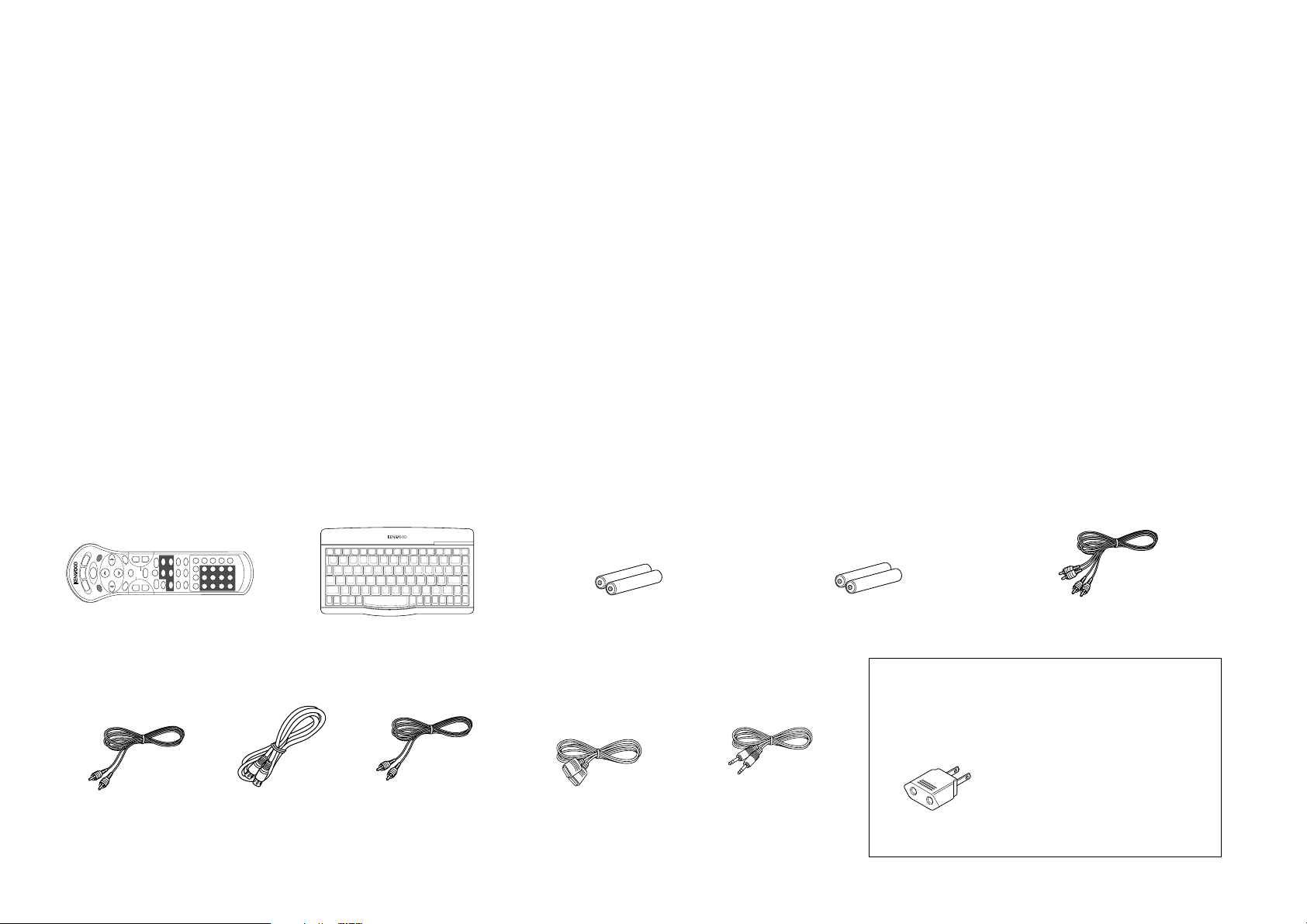
0-4 Accessories
Standard remote
control unit (1)
Video cable
(1)
S-Video cable
(1)
Keyboard remote
control unit (1)
DV-5900M only
REMOTE CONTROL UNIT RC-KB2
Coaxial cable
(1)
Batteries (R6/AA) (2)
(DV-5900M only)
RS-232C cable
(1)
Batteries (R03/AAA) (2)
System control cable
(2)
DV-5900M ................................... (3)
DV-5050M/DVF-J6050 ...............(1)
Audio cables
For countries other than U.S.A., U.S.-Military,
Canada, Europe and U.K.
AC plug adapter (1)
Use to adapt the plug on the power
cord to the shape of the wall outlet.
(Accessory only for regions where use
is necessary.)
3
Page 4

0-5 Features
Compatible with DVD AUDIO, one of the latest
digital audio formats (DV-5900M only)
The DVD AUDIO reproduces 2-channel, 192 kHz, 24bit sampled digital audio or 6-channel, 96 kHz, 24bit sampled audio. This innovative technology has
made possible audio reproduction in unprecedented
high quality. Picture information and character
information (ALBUM TEXT) are also provided.
Versatile DVD VIDEO Functions
The DVD VIDEO provides horizontal resolution of
430 lines, which exceeds that of DVD or S VHS video
(400 lines) or laserdisc (430 lines).
Multi-audio function: With DVD discs marked with
the 8 icon, the desired language can be played back
by selecting it from up to 8 languages. (The number
of available languages is variable depending on the
discs.)
Multi-subtitle function: With DVD discs marked
with the 32 icon, the subtitle language can be
selected from up to 32 languages. (The number of
subtitle languages is variable depending on the discs.)
Angle function: With DVD discs marked with the
icon, a single object can be viewed in up to 9
9
angles by switching. (The number of available angles
is variable depending on the discs.)
Compatibility with Wide Range of Digital Surround
Software
The unit incorporates Dolby Digital decoder, DTS
decoder, MPEG multi-channel decoder and Packed
PCM decoder so that the users can enjoy the sound
of real cinemas. The unit can also be connected to
the user's existing TV set
6-Channel Output Terminals (DV-5900M only)
These output terminals can be connected to an
amplifier with 6-channel input compatibility to enjoy
high-bit, high-sampling rate multi-channel sound.
DVD player with CD-R and CD-RW disc compatibility
This DVD player can play back tracks recorded in CDR (Compact Disc Recordable) and CD-RW (Compact
Disc Rewritable) as well as those in music CD.
* Only finalized discs can be played back.
MP3 file playback capabilities
This DVD player can also play back the MP3 files
which are the latest formats for storage of music data.
400-Disc mega changer
The DVD mega changer accommodates 400 plus 3
discs, the largest number in the industry.
Daisy chain connection
Up to three units can be played, making it possible
to play up to 1200 discs continuously.
Progressive scanning (NTSC area only)
The video projection method can be switched
between “Interlaced” and “Progressive” scanning
according to the area in which this unit is used.
Two-side playback
Double-sided DVD disc can be played back without
the troublesome disc return operation. The played
side of disc can simply be switched with a one-touch
operation (DISC FLIP).
Title input facility
Character information such as the disc and track titles
can be input on this unit.
Keyboard remote control unit (DV-5900M only)
This facilitates the title input operations.
PLUS1 - PLUS3 slots
The discs in these slots can be played or ejected with
one-touch operation, without the need of designating
the disc number. In addition, these slots are provided
with wider areas around the grooves to facilitate
insertion and ejection of discs.
DVD control function (Except for Asia)
The basic operations of this unit, such as playback
and stop, can be remote controlled from the LCD
remote control unit provided with a KENWOOD AV
receiver.
This instruction manual is for some models. Model
availability and features (functions) may differ
depending on the country and sales area.
4
Page 5

0-6 Contents
Caution : Read the pages marked carefully to ensure safe operation.
0-1 Before applying power ........................................2
0-2 Safety precautions ............................................... 2
0-3 Unpacking ........................................................... 3
0-4 Accessories ..........................................................3
0-5 Features ...............................................................4
0-6 Contents..............................................................5
0-7 Systems and Types of Playable Discs ...................7
0-7-1 Media that can be played back with this equipment
(CD-R, CD-RW) ........................................................ 7
0-7-2 Playback of CD-R and CD-RW discs ........................ 7
0-8 Unplayable Discs .................................................7
0-9 Icons Inscribed on DVD Discs ............................. 8
0-10 Region Codes of This Player ................................ 8
0-11 Region codes of the DVD VIDEO discs that can be
played with this player ........................................9
0-12 Video Formats ..................................................... 9
0-12-1 TV formats in major countries ................................. 9
0-12-2 Checking the Video Format ...................................... 9
0-12-3 When the video formats are different ...................... 9
0-13 MP3 File That Can Be Played Back with This
Equipment ........................................................ 10
Chapter 1: Connection of Equipment
1-1 Introduction...................................................... 11
1-2 Preparation of Standard Remote Control Unit
................................................................... 12
1-3 Preparation of Keyboard Remote Control Unit
................................................................... 12
1-4 STANDBY mode ................................................. 12
1-5 Connection of Video Outputs ........................... 13
1-5-1 To Setup of the Player ............................................. 13
1-5-2 Connection .............................................................. 13
1-6 Connection of Audio Output .............................15
1-6-1 2-channel stereo connection .................................. 15
1-6-2 6 channnel (5.1 ch) audio connection ................... 16
1-6-3 Digital output connection ....................................... 16
1-7 Daisy Chain Connection .................................... 18
1-7-1 Setup ........................................................................ 18
1-7-2 Connection of Video Output Terminals ................ 18
1-7-3 Connection of Audio Output Terminals ............... 19
1-8 PC Link Connection .......................................... 20
1-9 DVD Control Function ...................................... 20
Chapter 2: Controls and indicators
2-1 Introduction...................................................... 21
2-2 Front Panel ........................................................ 22
2-3 Display ..............................................................23
2-3-1 Switching the Display Brightness ........................... 23
2-4 Standard Remote Control Unit ......................... 24
2-5 Keyboard Remote Control Unit ......................... 26
Chapter 3: Basic Operation
3-1 Introduction...................................................... 27
3-2 Configuration of Discs ...................................... 28
3-3 Turning power on .............................................. 28
3-4 Inserting discs ................................................... 29
3-5 In regard to ALL DATA READ mode ...................29
3-6 Operation restriction according to the disc or
player status......................................................30
3-7 Playing discs ...................................................... 30
3-8 PLUS1 to PLUS3 slots........................................ 30
3-9 Playing discs by changing them ........................ 30
3-10 Playing from the selected disc ...........................30
3-11 Playing discs by selecting the title, chapter, track or
file ................................................................... 31
3-12 Skipping a track, chapter or file ........................ 31
3-13 Stopping playback ............................................. 31
3-14 Still picture display and playback pause ........... 31
3-15 Frame-by-frame advance .................................... 31
3-16 Forward search and reverse search ................... 32
3-17 Slow playback and reverse slow playback ......... 32
3-18 What is the “normal play TRACK mode”? .......... 32
3-19 Menu playback of DVD ...................................... 33
3-20 Menu playback of P.B.C.-compatible VCD ......... 33
3-20-1 Hierarchical structure of VCD menus .................... 33
3-20-2 Main control buttons used in VCD playback, and
examples of indications ........................................... 33
3-20-3 Switching P.B.C. On and Off ................................... 33
3-21 Switching still pictures of DVD AUDIO .............34
3-22 Switching the sequential play mode .................. 34
3-23 Repeat playback ................................................. 34
3-23-1 OSD icons that can be selected with each disc type and
mode ........................................................................ 35
3-24 Switching the time display ................................ 36
3-25 Pure Audio function .......................................... 36
3-26 Switching the audio language ........................... 36
Chapter 4: OSD Operation
4-1 Introduction...................................................... 37
4-2 Basic OSD Operation ........................................ 38
4-3 "MAIN" OSD Operation ..................................... 39
4-3-1 Selecting the disc to be played ............................... 39
4-3-2 Selecting a group, title, folder, chapter, track or file ..... 39
4-3-3 Time display switching and time search ..................... 40
5
Page 6

0-6 Contents
Caution : Read the pages marked carefully to ensure safe operation.
4-3-4 Memory playback ..................................................... 40
4-3-5 Repeat playback ........................................................ 41
4-3-6 A-B repeat playback ................................................... 42
4-4 "SOUND" OSD Operation ................................. 43
4-4-1 Switching the audio language ................................ 43
4-4-2 Virtual Surround function ...................................... 43
4-4-3 Cinema Voice function ........................................... 44
4-4-4 Down Mix function ................................................ 44
4-5 "VISUAL" OSD Operation ..................................45
4-5-1 Switching the subtitle language ............................. 45
4-5-2 Adjusting the picture quality .................................. 45
4-5-3 Switching the viewing angle ................................... 47
Chapter 5: Applied Operations
5-1 Introduction...................................................... 48
5-2 Switching the Play Modes ..................................49
5-3 Program Playback ............................................. 49
5-3-1 Registering and playing the program ..................... 49
5-3-2 Checking the program ............................................ 50
5-3-3 To change a track in the program........................... 50
5-3-4 Clearing the program .............................................. 50
5-4 Random playback .............................................. 50
5-4-1 Stopping random playback .................................... 50
5-5 TEXT DISC Operation........................................ 51
5-5-1 Switching the character information ..................... 51
5-6 Daisy chain function ......................................... 52
5-6-1 Turning power on ................................................... 52
5-6-2 Features available with daisy chain connection .... 52
5-6-3 Operation procedure .............................................. 52
5-7 Switching the "DVD Video Mode" .....................53
5-8 Playback of Double-Sided DVD .........................53
5-9 Bonus Group ..................................................... 53
Chapter 6: Specifying and Using Disc or
Track Data
6-1 Introduction...................................................... 54
6-1-1 The DVD mega-changer can ...............................55
6-1-2 Steps of MODE button operation ....................... 55
6-2 Listening to music by genre .............................. 56
6-2-1 Registration of music type ...................................... 56
6-2-2 Playing the music type ............................................ 56
6-2-3 To clear the music type ........................................... 57
6-3 Reorganizing discs to desired groups ............... 57
6-3-1 Registration of user file ........................................... 57
6-3-2 Playing the user file ................................................. 58
6-3-3 To clear the user file ................................................ 58
6-3-4 To initialize the user file ......................................... 58
6-3-5 Assigning user file names ....................................... 59
6-4 Registration of Title .......................................... 61
6-4-1 Assigning Title ......................................................... 61
6-5 Disc search ........................................................ 64
6-5-1 Disc search using the remote control unit............. 64
6-5-2 Disc search using the OSD ..................................... 66
6-6 Searching a desired folder/file by its title ......... 70
Chapter 7: Various Setups
7-1 Introduction...................................................... 71
7-2 Basic Operations in Setup Screen ..................... 72
7-3 "MAIN" Setting ..................................................73
7-3-1 When "MAIN" is selected in "SET UP MENU" ..... 73
7-3-2 "Rating" Setting ....................................................... 75
7-3-3 Input of Password ................................................... 75
7-4 "SOUND" Setting...............................................76
7-4-1 When "SOUND" is selected in "SET UP MENU" ....... 76
7-4-2 "Speaker Setting" ..................................................... 78
7-4-3 Delay Time Setting .................................................. 81
7-5 "VISUAL" Setting ............................................... 82
7-5-1 When "VISUAL" is selected in "SET UP MENU" ........ 82
7-5-2 Disc Language Code Table...................................... 85
Chapter 8: Other Information
8-1 Malfunction of Microcomputer ......................... 86
8-2 To Be Noted .......................................................87
8-3 Troubleshooting ................................................ 89
8-4 Glossary ............................................................ 91
8-5 Specifications ....................................................94
6
Page 7
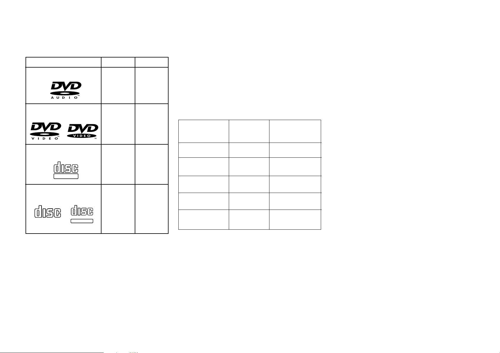
0-7 Systems and Types of Playable Discs
DV-5900M
DVD AUDIO
Yes
DVD VIDEO
Yes
Other
–
Yes
0-7-1 Media that can be played back with this
equipment (CD-R, CD-RW)
Usable media apart from audio CDs (CD-DA)
Usable media : CD-ROM, CD-R, CD-RW
Usable formats : ISO9660 level 1 (excluding
expanded formats)
Representative disc formats
Optical Disc Format
Playback on
This Unit
Applicable Disc
Types
÷ This unit cannot play back a disc written with
packet writing.
÷ This unit can play back the discs written with the
following writing methods:
Disc At Once
Track At Once
Session At Once
÷ This unit can play back only the closed sessions.
÷ This unit can play back only the finalized discs.
COMPACT
DIGITAL AUDIO
VCD
COMPACT
DIGITAL VIDEO
CD
DIGITAL AUDIO
COMPACT
TEXT
Yes
Yes
Yes
Yes
CD-DA
CD-ROM
MODE 1
CD-ROM
MODE 2
CD-ROM XA
MODE 2 Form 1
CD-ROM XA
MODE 2 Form 2
Yes
Yes
No
Yes
No
Music CD, etc.
CD-ROM (Yellow
book), etc.
CD-I, etc.
Video CD, etc.
Photo CD, etc.
0-7-2 Playback of CD-R and CD-RW discs
The playback of these discs may be restricted depending
on the status of data written in the discs. Certain CD-R
and CD-RW discs may be unable to be played back on
this unit even when they have been written according to
the above condition as described below.
0-8 Unplayable Discs
Never attempt to play a 8 cm disc on this unit.
Otherwise, the disc data may be destroyed.
Other discs which cannot be played on this unit:
¶ Photo CD, SACD, DVD-ROM, DVD-R/RAM, DVD-
RW, VSD, CDV*, CD-G*, CD-EG*, CD-EXTRA*,
etc.
* Only the audio part can be reproduced.
¶ A DVD VIDEO disc with a region code which does
not match this unit or without a region code. For
details, see "Region Codes of This Player".8
¶ When the video format of a disc differs from that
of the TV in use, the disc cannot be played normally.
For details, see "Video Formats". 9
7
Page 8
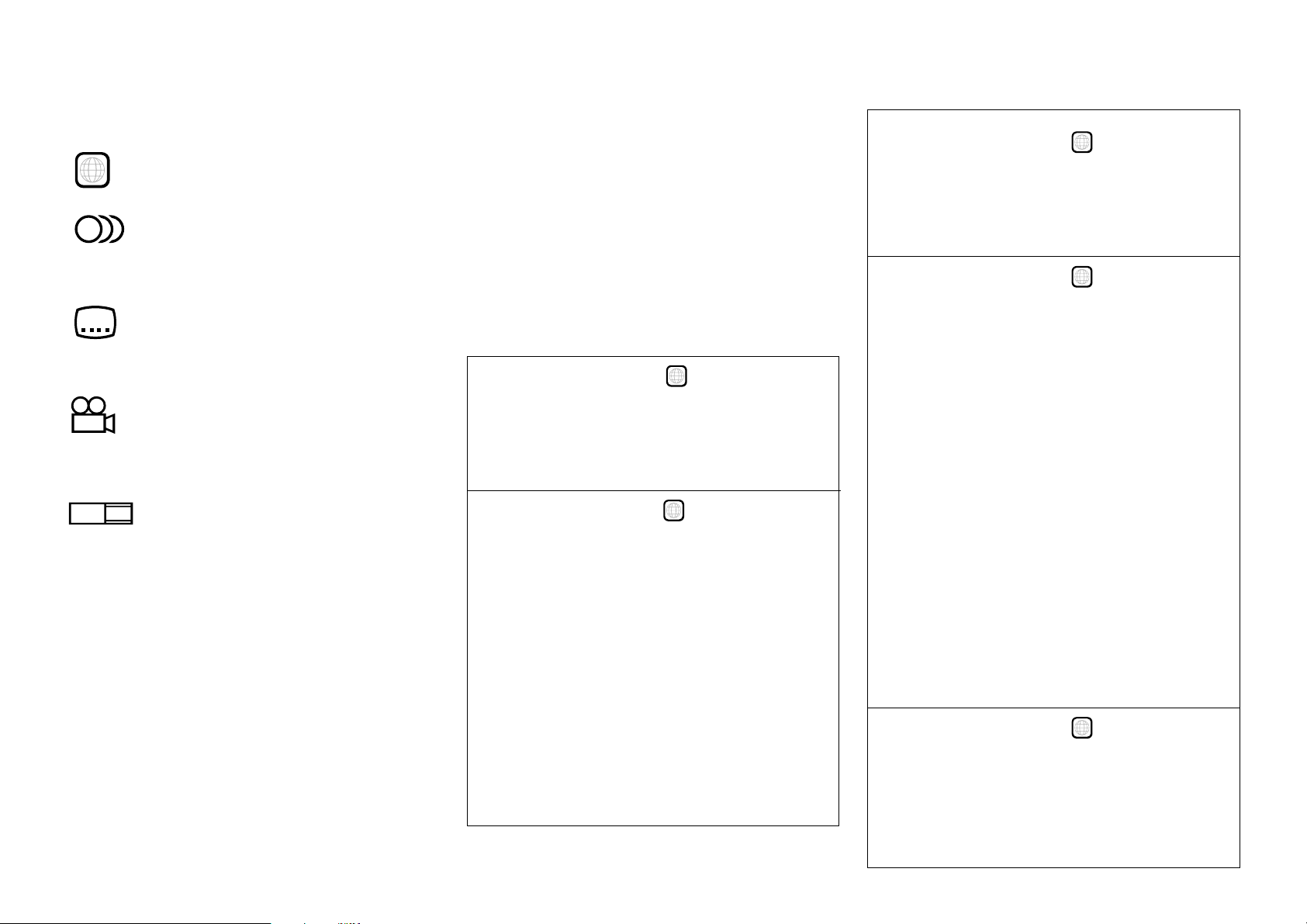
0-9 Icons Inscribed on DVD Discs
ALL
Indicates the playable region code.
8
Indicates the number of languages in the audio.
The figure in the icon shows the number (max. 8
languages).
32
Indicates the number of available subtitle
languages. The figure in the icon shows the number (max.
32 subtitle languages).
9
Indicates the number of viewing angles which
can be viewed with the angle function. The figure in the
icon shows the number (max. 9 angles).
16:9 LB
LB stands for Letter Box and PS stands for Pan & Scan.
(The example shown means that the 16:9 video can be
converted into letterbox.)
Indicates the number of available aspect ratios.
0-10 Region Codes of This Player
(DVD VIDEO disc only)
A region code defined for each country or area is
assigned for each DVD VIDEO player, so it cannot play
a DVD VIDEO disc if its region code do not match
that of this unit. Also, a disc which does not contain
any region code may sometimes be unable to be played
on the player.
When purchasing a DVD VIDEO disc, make sure that
it has a region code which can be played on your player.
Region Code of Player:
Usable Country or Area : Canada, United States,
American Samoa, Bermuda, Johnston Island,
Midway Islands, Puerto Rico, St. Pierre and
Miquelon, United States Virgin, Wake Island
Region Code of Player :
Usable Country or Area : Albania, Andorra, Austria,
Bahrain, Belgium, Bosnia and Herzegovina,
Bulgaria, Croatia, Cyprus, Czech, Denmark, Egypt,
Finland, France, Germany, Greece, Hungary,
Iceland, Iran, Iraq, Ireland, Israel, Italy, Japan,
Jordan, Kuwait, Lebanon, Lesotho, Liechtenstein,
Luxembourg, Macedonia, Malta, Monaco,
Netherlands, Norway, Oman, Poland, Portugal,
Qatar, Romania, San Marino, Saudi Arabia,
Slovakia, Slovenia, South Africa, Spain, Swaziland,
Sweden, Switzerland, Syrian Arab Republic, Turkey,
United Arab Emirates, United Kingdom, Vatican
City State, Yemen, Yugoslavia, Channel Islands,
Faeroe Islands, Gibraltar, Greenland, Isle of Man,
Svalbard and Jan Mayen Islands
1
2
Region Code of Player :
Usable Country or Area : Brunei Darussalam,
Cambodia, Indonesia, Korea, Laos, Malaysia,
Myanmar, Philippines, Singapore, Thailand, Viet
Nam, East Timor, Hong Kong, Macau, Taiwan
Region Code of Player :
Usable Country or Area : Antigua and Barbuda,
Argentina, Australia, Bahamas, Barbados,
Belize, Bolivia, Brazil, Chile, Colombia, Costa
Rica, Cuba, Dominica, Dominican Republic,
Ecuador, El Salvador, Fiji, Grenada,
Guatemala, Guyana, Haiti, Honduras,
Jamaica, Kiribati, Marshall Islands, Mexico,
Micronesia, Nauru, New Zealand, Nicaragua,
Palau, Panama, Papua New Guinea, Paraguay,
Peru, Saint Christopher and Nevis, Saint Lucia,
Saint Vincent and the Grenadines, Samoa,
Solomon Islands, Suriname, Tonga, Trinidad
and Tobago, Tuvalu, Uruguay, Vanuatu,
Venezuela, Anguilla, British Virgin Islands,
Cayman Islands, Christmas Island, Cocos
Islands, Cook Islands, Falkland Islands, French
Guiana, French Polynesia, Guadeloupe, Guam,
Martinique, Montserrat, Netherlands Antilles,
New Caledonia, Niue, Norfolk Island, Northern
Mariana Islands, Pitcairn, Tokelau, Turks and
Caicos Islands, Wallis and Futuna Islands
Region Code of Player :
Usable Country or Area : Afghanistan, Algeria,
Angola, Armenia, Azerbaijan, Bangladesh, Belarus,
Benin, Bhutan, Botswana, Burkina Faso, Burundi,
Cameroon, CapeVerde, Central Africa, Chad,
Comoros, Congo, Cote d'Ivoire, Djibouti,
3
4
5
8
Page 9
Equatorial Guinea, Eritrea, Estonia, Ethiopia,
Gabon, Gambia, Georgia, Ghana, Guinea, GuineaBissau, India, Kazakhstan, Kenya, Kyrgyz Republic,
Latvia, Liberia, Libya, Lithuania, Madagascar,
Malawi, Maldives, Mali, Mauritania, Mauritius,
Moldova, Mongolia, Morocco, Mozambique,
Namibia, Nepal, Niger, Nigeria, North Korea,
Pakistan, Russia, Rwanda, Sao Tome and Principe,
Senegal, Seychelles, Sierra Leone, Somalia, Sri
Lanka, Sudan, Tadzhikistan, Tanzania, Togo,
Tunisia, Turkmenistan, Uganda, Ukraine,
Uzbekistan, Zaire, Zambia, Zimbabwe, British
Indian Territory, Jammu and Kashmir, Mayotte,
Reunion, St. Helena ex. dep., Western Sahara
0-12 Video Formats
The TV picture display and disc signal systems can be
divided roughly into two TV formats (NTSC and PAL).
They are variable depending on countries and areas.
This unit reproduces NTSC discs in NTSC format and
PAL discs in PAL format. If the video formats of the disc
and TV do not match, the disc cannot be reproduced
correctly. It is therefore required to select the disc
according to the TV set in use (country and area).
TV Format Playable Disc Format
NTSC only *
PAL only
NTSC/PAL
switchable
¶ Correct video cannot be reproduced if the video formats
of the TV and disc do not match.
NTSC*
PAL
NTSC/PAL
Region Code of Player :
Usable Country or Area : ChinaCaicos Islands,
Wallis and Futuna Islands
Region Code of Player :
Professional use disc (Air Line cabin service)
6
8
0-11 Region codes of the DVD VIDEO discs that can be played with this player
This player can play back a DVD VIDEO disc which carries
the corresponding code to the region code of the player
shown in the table above, a marking containing the
region code of the player or the “ALL” marking shown
below. Even when a DVD VIDEO disc does not carry any
indication of the region code, it may sometimes unable
to be played on this player due to certain restrictions.
ALL
0-12-1 TV formats in major countries
NTSC : Japan, Taiwan, Korea, USA, Canada, Mexico,
Philippines, Chile, etc.
PAL : China, U.K., Germany, Australia, New Zealand,
Kuwait, Singapore, etc.
0-12-2 Checking the Video Format
Check the video format of the VCD and DVD discs to be
played on the player as described below.
1. Check if the video formats of the TV to be used and
disc to be played match each other.
¶ For details, refer to the instructions provided with
the TV and disc.
2. When the TV is switchable between NTSC and
PAL, set the TV format according to the disc format.
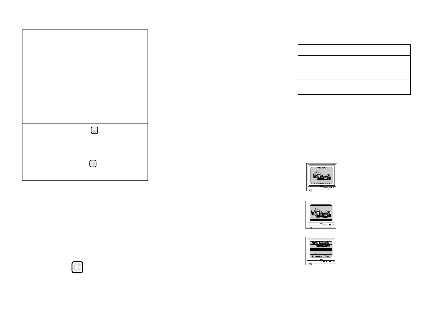
0-12-3 When the video formats are different
Try playing the disc. If the video formats of the disc and
TV do not match, the played video may be black and
white or become as shown below.
Top and bottom edges are not
displayed.
Top and bottom areas are
dark.
Picture turbulence due to sync
unmatching.
9
Page 10

0-13 MP3 Files That Can Be Played Back with This Equipment
Compressing MP3 files
Please set up the transfer bit rate setting for the
compression software when compressing MP3 files as
follows:
MP3 file
128kbps recommended (32 kbps-320 kbps)
÷ This unit is compatible with 32kHz, 44.1kHz
(recommended) and 48 kHz samplimg frequencies.
Categorizing folders
As MP3 files are compressed into high-quality sound files
at an extremely high rate of compression, it is possible
to record several times more tracks than audio CDs onto
a single medium. It is therefore convenient to split the
tracks into different folders by genre, artist or album for
retrieval and repeat playback purposes.
÷ A maximum of 999 folders or a maximum of 999
files can be stored on a single media.
÷ There are cases where it is not possible to save
folders in the desired sequence depending on the
software being used.
Additional information
Usable formats :
ISO9660 level 1 (excluding expanded formats)
Text display
Both file and folder names are displayed in up 8
uppercase alphanumeric characters.
Time display
With a MP3 files, only the "Single Time" information is
displayed.
ID3-TAG infomation
This unit is not compatible with this function.
“Digital” output from MP3 files
This unit does not output the “Digital” signal when it
plays back an MP3 files.
Restriction by session
This unit can play back only the closed sessions.
With CD-DA
With a multi-session disc, this unit plays back the first
session only.
With MP3 files
Note on the multi-session disc and CD-DA (music
data)
÷ This unit is compatible with multi-session discs.
÷ The music CD data (CD-DA data) can be played
only when its first session is composed of music
CD data (CD-DA data).
The second and later sessions are not played back.
Never add the MP3 extension logs to any files other than
MP3 files. If the MP3 extension logs are added to any
files other than MP3 files, the equipment will assume
that they can be played back, and this will produce loud
noises in the speakers, resulting in damage of adverse
effects.
Check to ascertain that MP3 files can be played back
correctly on the personal computer in use prior to saving
them onto the media. Check to ensure that the saved
file can be played back normally.
÷ It is not possible to confirm that files can be played
back correctly while they are being saved onto the
media.
Ensure that the session is closed or finalized when data
has been written on media. There are cases where media
on which the session has not be closed or finalized will
not be played back correctly with this equipment.
÷ There are cases were the folder names and file
names will not be displayed correctly depending
on the software used to save them.
÷ There are cases where playback is not possible
when MP3 files (CD-ROM) and music CD
information (CD-DA) are saved on the same
media.
÷ When a disc contains a mixture of different formats
such as the CD-DA and MP3, the data in the CDDA format will be played in priority.
10
However, when "the number of sessions is '2'" and
"its second session is composed of music CD data
(CD-DA data)", the music CD data (CD-DA) can
be played back.
Page 11

Chapter 1: Connection of Equipment
Chapter 1: Connection of Equipment
1-1 Introduction
This manual describes the standard, most typical connections of the player. When an associated system component is connected, also refer to their instruction manuals.
For details on the connection of the following components, see the indicated reference pages.
Preparation of Standard Remote Control Unit..................... @
Preparation of Keyboard Remote Control Unit .................... @
STANDBY mode ..................................................................... @
Connection of Video Outputs ............................................... #
Connection of Audio Output ................................................ %
Daisy Chain Connection ....................................................... *
PC Link Connection .............................................................. )
DVD Control Function .......................................................... )
Before Start
Do not install the player in a place where the remote
control sensor is subjected to direct sunlight or the light
of a fluorescent lamp base on high-frequency lighting
(inverter system, etc.). Otherwise, the control range of
the standard remote will be reduced.
Chapter 1
Chapter 2
Chapter 3
Chapter 4
Chapter 5
Chapter 6
Do not insert the power cord plugs of the player and the
connected components until all of the components have
been connected.
Be sure to insert all connection cables securely. If a cable
is plugged incompletely, lack of video, lack of audio or
noise may result.
Before connecting or disconnecting a connection cord,
be sure to unplug the power plug from the wall power
outlet. If a connection cable is connected or disconnected
while the power plug is left connected, malfunction or
equipment damage may result.
CAUTION
Be sure to adhere to the following, or proper ventilation will be blocked causing damage or fire hazard.
÷ Do not place any objects impairing heat radiation onto the top of the unit.
÷ Leave some space around the unit (from the largest outside dimension including projection) equal to or greater
than, shown below.
Top panel : 10 cm Side panel : 10 cm Back panel : 10 cm
Chapter 7
Chapter 8
11
Page 12
Chapter 1: Connection of Equipment
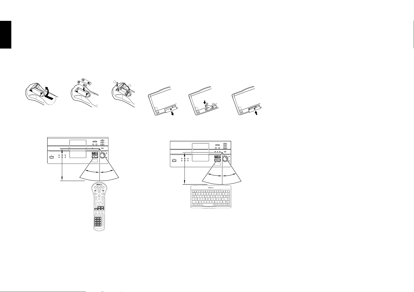
1-2 Preparation of Standard Remote Control Unit
Chapter 1Chapter 2Chapter 3Chapter 4Chapter 5
Installing the batteries:
Open the cover and insert the batteries (R03/AAA) by
observing the polarity marking.
\ \
Remote control range:
6m
30° 30°
1-3 Preparation of Keyboard Remote
Control Unit (DV-5900M only)
Installing the batteries:
Open the cover and insert the batteries (R6/AA) by
observing the polarity marking.
1
2
1-4 STANDBY mode
While the "STANDBY" indicator of the unit is lit, a small
amount of current is flowing into the unit’s internal
circuitry to back up the memory. This condition is
referred to as the standby mode of the unit. While the
unit is in the standby mode, it can be turned on from
the remote control unit.
\\
Remote control range:
3m
30° 30°
REMOTE CONTROL UNIT RC-KB2
Chapter 6
Chapter 7
Chapter 8
12
¶ When the controllable distance of the keyboard
remote reduces, replace both batteries with new
ones.
¶ When the controllable distance of the standard
remote reduces, replace both batteries with new
ones.
Page 13
Chapter 1: Connection of Equipment
D
1-5 Connection of Video Outputs
This unit can be connected to a TV through the following connections.
Composite VIDEO OUTPUT connectors
S-VIDEO OUTPUT connectors
COMPONENT VIDEO OUTPUT connectors
SCART connector (For Europe and U.K.)
Select the connection according to the TV to be connected.
After connecting the TV, be sure to change the setup of the unit according to the TV.
÷ Do not insert the power cord plugs of the player and the connected components
until all of the components have been connected.
÷ For details on the connection terminals and functions of the TV, refer to its
instruction manual.
1-5-1 To Set Up of the Player
Setup of Menu screen: The language to be used in the menus of the player can
be selected.
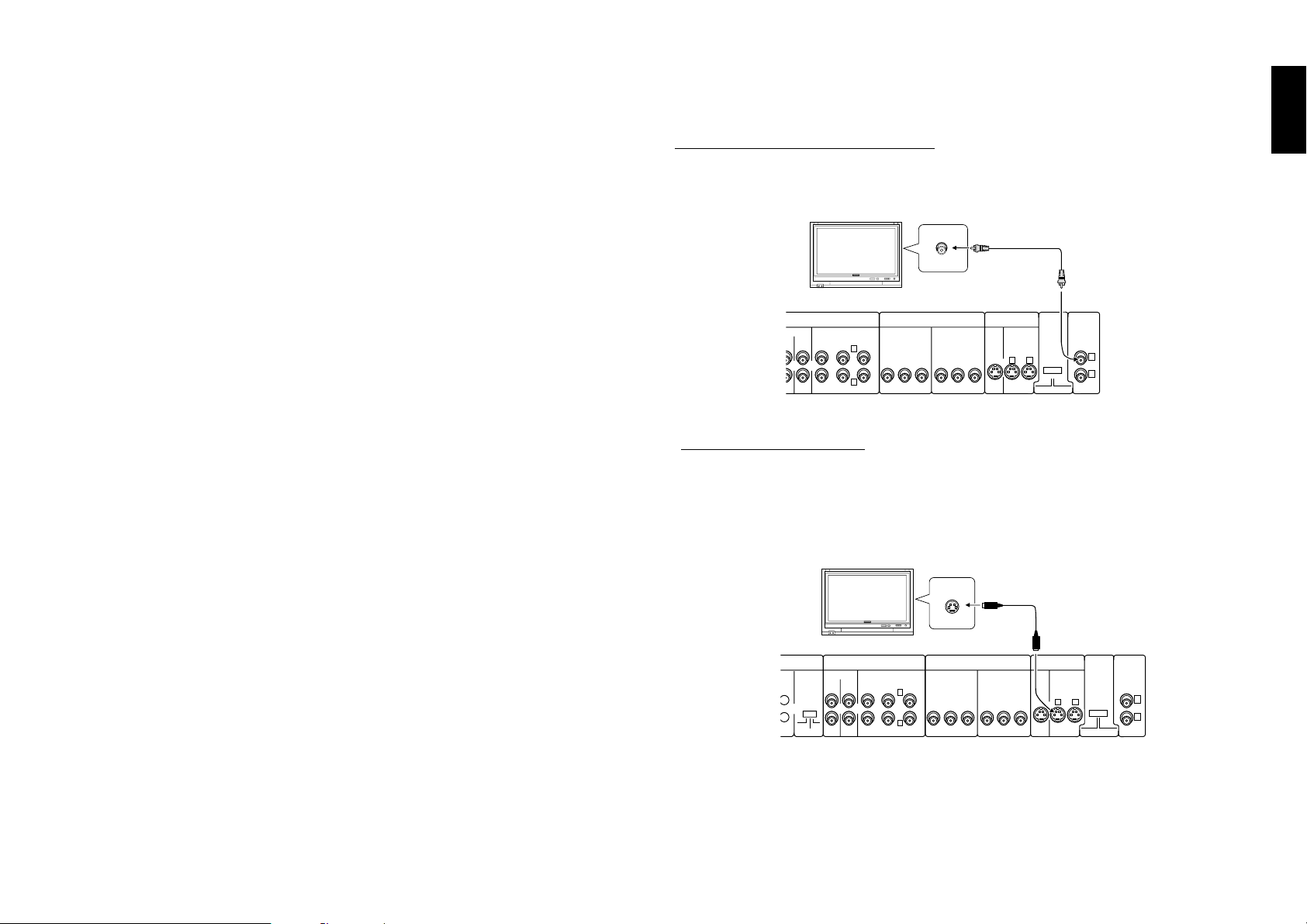
1-5-2 Connection
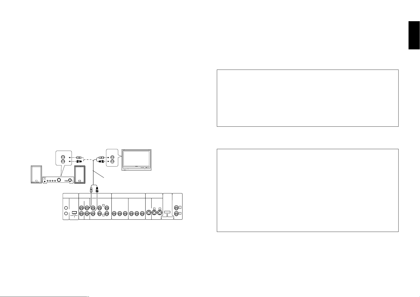
a : Composite video connection
Connect the VIDEO OUTPUT terminal to the video input of the TV using the provided video cable.
IX LINE
UT OUTPUT
AUDIO
6 CH. OUTPUT
SURROUND
FRONT
CENTER
L
YCBCRYCBC
R
SUB WOOFER
VIDEO
IN
COMPONENT VIDEO
INPUT
S VIDEO
INPUT
OUTPUT OUTPUT
R
Video cable (Provided)
VIDEO
OUTPUT
COMPONENT
VIDEO
1
OUTPUT
21
INTERLACE PROGRESSIVE
2
Illust Model : DV-5900M
b : S Video connection
If the TV has an S Video input connector, connect the S VIDEO OUTPUT connector
of the player to it using the provided S Video cable.
¶ As S Video separates video signal into the brightness signal (Y) and color signal
(C), it can provide sharper pictures than composite video connection.
Chapter 1
Chapter 2
Chapter 3
Chapter 4
Chapter 5
"Player Menu Language" Setting S
÷ The default language set at the factory is English.
S VIDEO
IN
S-Video cable (provided)
Chapter 6
Setups Related to TV: The following setups can be made according to the TV
COMPONENT
VIDEO
21
OUTPUT
INTERLACE PROGRESSIVE
VIDEO
OUTPUT
Chapter 7
1
2
Chapter 8
connected to the player.
"TV Aspect" Setting d
"TV Mode" Setting d
"TV Monitor Type" Setting d
Setup of SCART output signals: The signals output from the TV SCART con-
nector of the player can be selected.
"SCART Output Select" Setting F
÷ If both connections “Composite video connection” and “S Video connection”
are made, “S Video connection” is used in priority on the main unit.
÷ For details on the connection terminals and functions of the TV, refer to its
instruction manual.
AISY CHAIN
NTROL
MAIN-SUB
SWITCH
MAIN
SUB2
SUB1
MIX LINE
INPUT OUTPUT
AUDIO
6 CH. OUTPUT
FRONT SURROUND
L
R
SUB WOOFER
Illust Model : DV-5900M
COMPONENT VIDEO
INPUT
CENTER
YCBCRYCBC
OUTPUT
S VIDEO
INPUT
OUTPUT
R
13
Page 14
Chapter 1: Connection of Equipment
Chapter 1Chapter 2Chapter 3Chapter 4Chapter 5
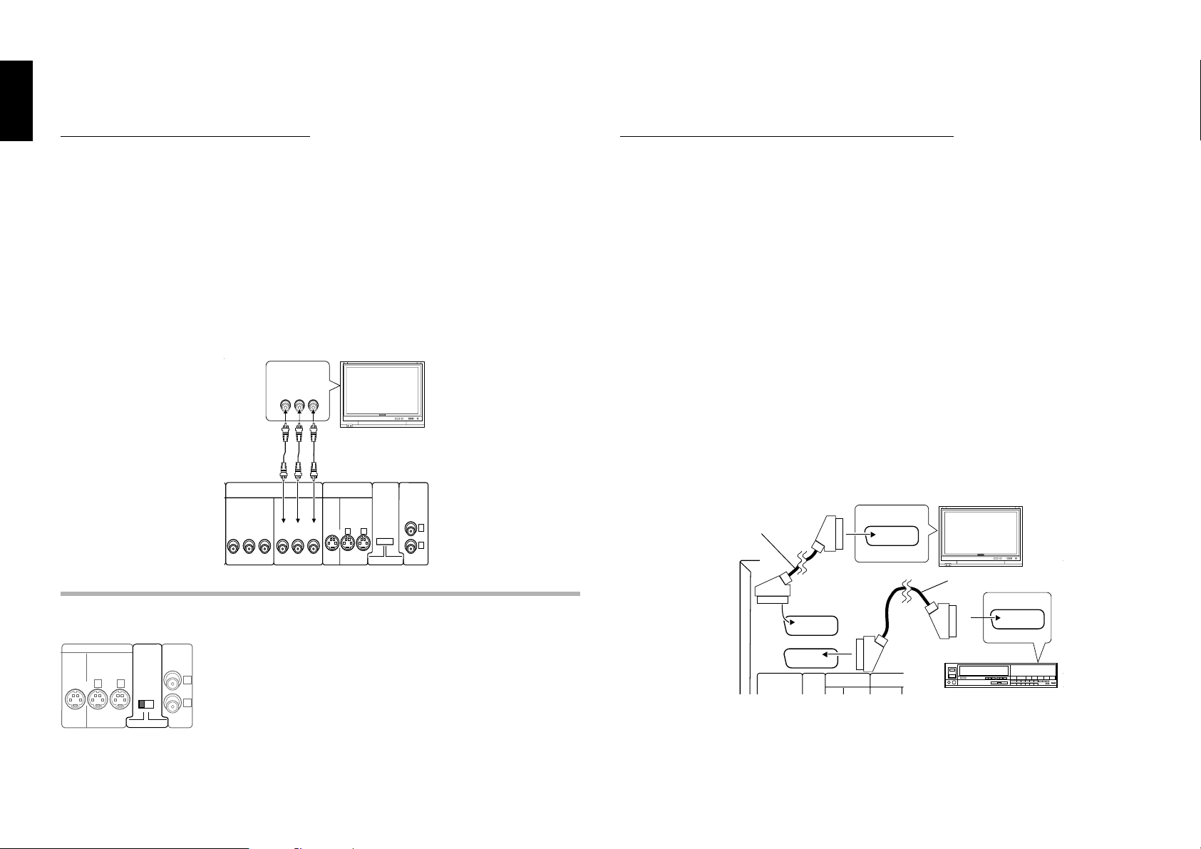
C : Component video connection
d : SCART connection (For Europe and U.K.)
If the TV has component video input terminals, connect the Y, CB and CR COMPONENT VIDEO OUTPUT terminals to the corresponding jacks on the TV using video
cables.
¶ As component video separate video signal into the brightness signal (Y) and
color difference signals (CB, CR), it can provide sharper image than the S Video
connection.
¶ Depending on the TV or video monitor in use, the terminal names may be
different from those used with the player (Y/Pb/Pr or Y/B-Y/R-Y, etc.)
¶ When the TV in use is a HDTV or "Hi-Vision" TV, connect the component video
signals from the player only to the DVD-compatible input jacks.
COMPONENT
VIDEO IN
YCbCr
Video cable
COMPONENT
VIDEO
OUTPUT
21
INTERLACE PROGRESSIVE
VIDEO
OUTPUT
1
2
COMPONENT VIDEO
INPUT
BCR
YC
OUTPUT
YCBC
S VIDEO
INPUT
OUTPUT
R
Illust Model : DV-5900M
Chapter 6
COMPONENT VIDEO OUTPUT switch (NTSC Format only)
If the TV or VCR has SCART connectors, connect the TV SCART or VCR SCART
connector of this unit to the TV or VCR using SCART cables.
¶ The audio and video signals can be output using a single cable. The signal output
from the TV SCART connector can be switched between composite video, S
Video and RGB. (The VCR SCART connector always outputs composite video
signals so its output signals cannot be selected.)
¶ When the TV is connected through a VCR using SCART connection, the picture
displayed on the TV may be disturbed due to the copy protect function.
¶ When using only the TV and VCR which are both connected with the player
using the SCART connection, the signal from the VCR cannot be sent to the
TV if the player is switched off. (In this case, set the player to the power
standby mode.)
¶ When the COMPONENT VIDEO OUTPUT connectors are used, do not set
“SCART Output Select” in the Set Up menu to “RGB”. F
SCART IN
SCART cable
SCART cable
TV SCART
SCART IN
INPUT OUTPUT
Chapter 7
Chapter 8
14
S VIDEO
112
COMPONENT
VIDEO
OUTPUT
INTERLACE PROGRESSIVE
VIDEO
OUTPUT
Select the scanning method of the Component Video output
using the COMPONENT VIDEO OUTPUT switch on the rear
panel.
2
INTERLACE : Scanning method is fixed at interlaced scanning.
PROGRESSIVE : When progressive scanning is unavailable with
certain discs, the scanning method is switched automatically to
interlaced scanning. When the unit is performing progressive
scanning, “PROGRESSIVE” light in the display.
DIGITAL
(PCM/BIT STREAM)
VCR SCART
DAISY CHAIN
AUDIO
COMPONENT VIDEO
VCR etc.
Page 15
Chapter 1: Connection of Equipment
1-6 Connection of Audio Output
Do not insert the power cord plugs of the player and the connected components until
all of the components have been connected.
For details on the connection terminals and functions of the AV amplifier, refer to its
instruction manual. The video output from the player should be connected directly
to the AV amplifier. If the video output is connected through a VCR, the picture
displayed on the TV may be disturbed due to the copy protect function.
1-6-1 : 2-channel stereo connection
You can enjoy stereo sound if you connect the TV or system component that has 2channel stereo connection.
DV-5900M
Connect to the MIX LINE OUTPUT connectors.
DV-5050M/DVF-J6050
Connect to the MIX LINE OUTPUT or AUDIO OUTPUT L/R connectors.
AUX IN
L
R
DAISY CHAIN
CONTROL
MAIN-SUB
SWITCH
MAIN
SUB2
SUB1
MIX LINE
INPUT OUTPUT
AUDIO
FRONT SURROUND
Illust Model : DV-5900M
AUDIO
IN
L
R
Audio cable (Provided)
6 CH. OUTPUT
L
R
SUB WOOFER
COMPONENT VIDEO
INPUT
CENTER
YCBCRYCBC
OUTPUT
COMPONENT
VIDEO
OUTPUT
21
INTERLACE PROGRESSIVE
VIDEO
OUTPUT
1
2
S VIDEO
INPUT
OUTPUT
R
For DV-5050M/DVF-J6050
DTS disclaimer clause
When playing DTS-encoded (CDs, LDs, DVDs), excessive noise will be exhibited
from the analog stereo outputs. To avoid possible damage to the audio system,
the consumer should take proper precautions when the analog stereo outputs of
the DVD player is connected to an amplification system. To enjoy DTS Digital
Surround™ playback, an external 5.1 channel DTS Digital Surround™ decoder
system must be connected to the digital output (S/P DIF, AES/EBU, or TosLink)
of the DVD player.
For DV-5900M
DTS disclaimer clause
DTS Digital Surround™ is a discrete 5.1 channel digital audio format available on
CD, LD, and DVD software which consequently cannot be decoded and played
back inside most CD, LD, or DVD players. For this reason, when DTS-encoded
software is played back through the analog outputs of the CD, LD, or DVD player,
excessive noise will be exhibited. To avoid possible damage to the audio system,
proper precautions should be taken by the consumer if the analog outputs are
connected directly to an amplification system. To enjoy DTS Digital Surround™
playback, an external 5.1 channel DTS Digital Surround™ decoder system must
be connected to the digital output (S/P DIF, AES/EBU, or TosLink) of the CD, LD
or DVD player.
This unit is equipped with DTS Digital Surround™ decoder.
Chapter 1
Chapter 2
Chapter 3
Chapter 4
Chapter 5
Chapter 6
Chapter 7
÷ When playing a disc containing MPEG multi-channel audio recording, connect
the stereo input to the 6ch OUTPUT L/R terminals and activate the DOWN
MIX function (r). (DV-5900M only)
÷ Read the instructions for the TV and speakers or system component for
connection details.
Chapter 8
15
Page 16
Chapter 1: Connection of Equipment
1-6-2 : 6 channnel (5.1 ch) audio connection (DV-5900M only)
Chapter 1Chapter 2Chapter 3Chapter 4Chapter 5
When the connected AV amplifier has 6-channel audio input terminals, Please connect the 6CH. OUTPUT terminals to them.
Speaker Setting
To 6ch Input terminal
DIGITAL
(PCM/BIT STREAM)
COAXIAL
OPTICAL
IN
OUT
OUT
DVD
CONTROL
DAISY CHAIN
CONTROL
MAIN-SUB
SWITCH
MAIN
INPUT OUTPUT
SUB2
SUB1
Illust Model : DV-5900M
Setup for 6-channel audio connection:
÷ When the audio is connected using the 6CH. OUTPUT terminals, set the player
as follows. "Speaker Setting" k
÷ When a DVD AUDIO disc is played, the player can output audio signals at very
high frequencies. As this may sometimes lead to speaker damage due to a highvolume sound, do not set "Audio Filter" to "Filter 110 kHz" when the speakers
in use are not suitable for high-frequency reproduction. j
Chapter 6
÷ When connection of 3 or more channels is required, connect the audio inputs
to the 6ch OUTPUT connectors on the rear panel according to the speakers in
use.
After connection, set the non-used speakers to “OFF” with the “Speaker setting”
function. k
Chapter 7
AUDIO
6 CH. OUTPUT
FRONT SURROUND
L
R
SUB WOOFER
COMPONENT VIDEO
INPUT INPUT
CENTER
YC
B CR YCB CR
OUTPUT
S VIDEO
OUTPUTMIX LINE
COMPONENT
VIDEO
OUTPUT
21
INTE RLACE PROGRESSIVE
VIDEO
OUTPUT
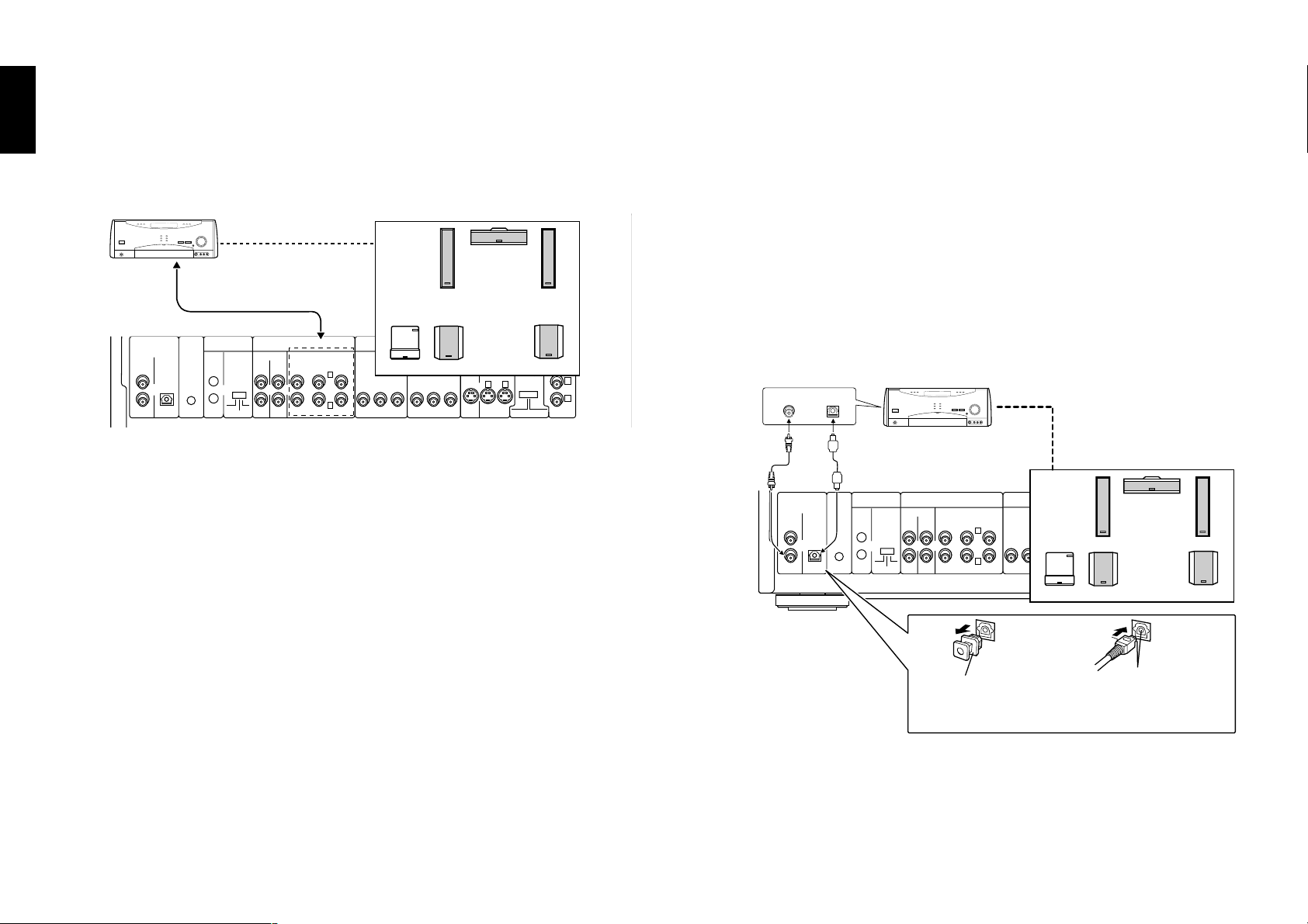
1-6-3 : Digital output connection
Use the DIGITAL output terminal when using an external decoder (or an AV amplifier
with built-in decoder) to decode Dolby Digital and DTS Digital Surround signals.
To use the external decoder, it is required to change the “SOUND” setup in the Set Up
menu. h
Speaker setting
The speakers are to be set up on the amplifier. k
Audio filter (Speaker protect)
The audio filtering is to be set up on the amplifier. j
1
2
Coaxial cable
(Provided)
Illust model : DV-5900M
Note : When connecting the optical digital audio cable
COAXIAL OPTICAL
or
DIGITAL
(PCM/BIT STREAM)
COAXIAL
OPTICAL
IN
CONTROL
OUT
OUT
Optical cable
DAISY CHAIN
CONTROL
MAIN-SUB
DVD
SWITCH
MAIN
SUB2
SUB1
Speaker Setting
COMPONENT VIDEO
INPUT INPUT
CENTER
YC
B CR YCB CR
OUTPUT
S VIDEO
OUTPUTMIX LINE
21
INPUT OUTPUT
AUDIO
6 CH. OUTPUT
FRONT SURROUND
L
R
SUB WOOFER
Dust protection cap Align the plug
with the terminal
OUTPUT
COMPONENT
VIDEO
OUTPUT
INTERLACE PROGRESSIVE
VIDEO
1
2
Chapter 8
16
÷ Remove the dust protection cap from the optical digital audio output terminal
and connect the cable firmly so that the configurations of both the cable and
the terminal match.
÷ Keep the dust protection cap and reattach when not using the terminal.
Page 17
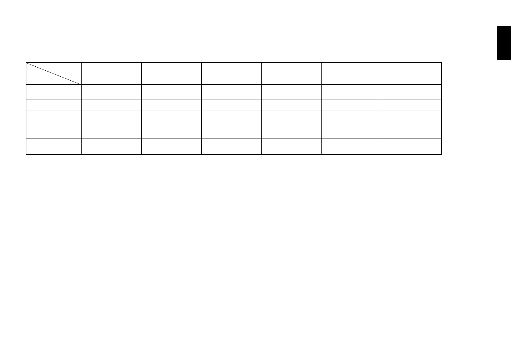
a : External decoder type & SetUp menu "sound"
External decorder
Setup Function
PCM Down
Conversion
Dolby Digital
DTS Digital
Surround
MPEG Multi
channel
Dolby Digital decorder DTS Digital Surround
type
Yes*
Bitstream
DV-5900M
PCM
Other
Off
PCM PCM
decorder
DV-5900M
Bitstream
Other
Bitstream
Yes *
PCM
MPEG decorder
Yes*
PCM
DV-5900M
PCM
Other
Off
Bitstream
* If this is set to "No", no audio will be output when DVDs recorded in 96 kHz linear PCM are played. (Audio
will be output as it is the DVD does not have copyright protection recorded on it.)
Dolby Digital/DTS
Digital Surround decorder
Yes*
Bitstream
DV-5900M
Bitstream
Other
Bitstream
PCM
Dolby Digital/DTS
Digital Surround/MPEG
decorder
Yes*
Bitstream
DV-5900M
Bitstream
Other
Bitstream
Bitstream
Chapter 1: Connection of Equipment
No decorder
Yes*
PCM
DV-5900M
PCM
Other
Off
PCM
Chapter 1
Chapter 2
Chapter 3
Chapter 4
These changes to digital audio output must be made, otherwise bitstream signals the decoder cannot
handle will be output. If these signals are output, "noise" will be output which can cause harm to your ears
and speakers.
Chapter 5
Chapter 6
Chapter 7
Chapter 8
17
Page 18
Chapter 1: Connection of Equipment
R
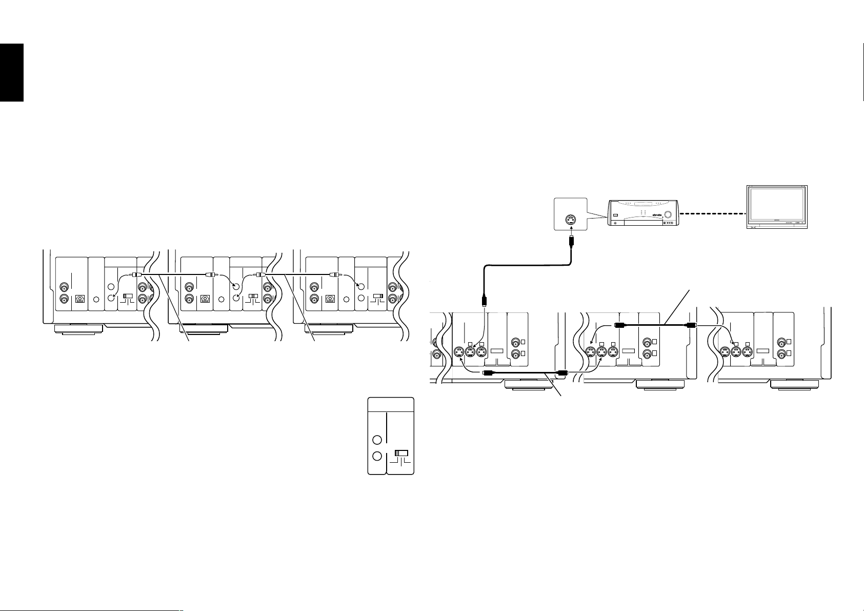
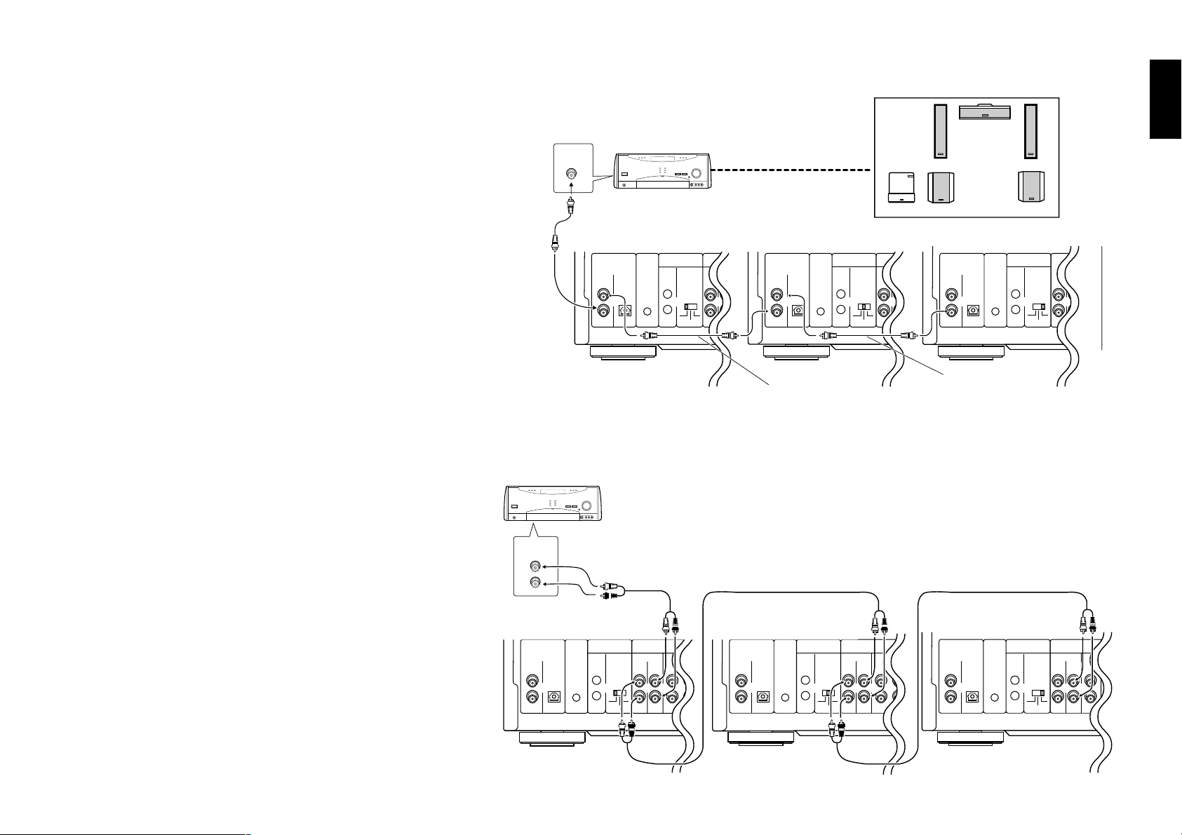
1-7 Daisy Chain Connection
Up to three changer units can be connected in series.
Chapter 1Chapter 2Chapter 3Chapter 4Chapter 5
÷ The three units can mutually control other units.
÷ Up to 1200 discs can be played back continuously by connecting three units.
÷ Relay playback, with which discs are played in a random order is possible.
Relay playback cannot control discs in the PLUS1 to PLUS3 slots.
1-7-2 Connection of Video Output Terminals
Connect the video output using either the S-VIDEO or COMPONENT VIDEO
connection.
For the connection, connect the “SUB2” unit output to the “SUB1” unit input, then
connect the “SUB1” unit output to the “MAIN” unit input as shown in the figure
below.
Random relay playback cannot play discs in the PLUS1 to PLUS3 slots.
Daisy Chain Connection
MAIN
DIGITAL
(PCM/BIT STREAM)
COAXIAL
OPTICAL
IN
OUT
DAISY CHAIN
CONTROL
DVD
CONTROL
OUT
MIX LINE
INPUT OUTPUT FRONT SURROUND
MAIN-SUB
SWITCH
MAIN
SUB2
SUB1
SUB 1
AUDIO
6 CH. INPUT
DIGITAL
(PCM/BIT STREAM)
COAXIAL
OPTICAL
IN
CENTER
L
YCbCr YCbCr
CONTROL
R
OUT
OUT
SUB WOOFER
COMPONENT VIDEO
DAISY CHAIN
INPUT INPUT
CONTROL
DVD
MIX LINE
OUTPUT OUTPUT
INPUT OUTPUT FRONT SURROUND
MAIN-SUB
SWITCH
MAIN
SUB2
SUB1
S VIDEO
SUB 2
AUDIO
6 CH. INPUT
21
System control cable
(Provided)
1-7-1 Setup
Set the MAIN-SUB SWITCH on the rear panel of each changer unit to a
different position from other changer units.
Chapter 6
Be sure to unplug the power cord before changing the position of the
MAIN-SUB SWITCH.
Be sure to set one of the MAIN-SUB SWITCH to “MAIN”.
DIGITAL
COMPONENT VIDEO
(PCM/BIT STREAM)
COAXIAL
OPTICAL
COMPONENT
IN
CENTER
L
VIDEO
OUTPUT
R
OUT
OUT
INTERLACE PROGRESSIVE
SUB WOOFER
DAISY CHAIN
VIDEO
INPUT INPUT
OUTPUT
1
DVD
YCbCr YCbCr
CONTROL
2
CONTROL
OUTPUT
MAIN-SUB
SWITCH
MAIN
SUB1
SUB2
INPUT OUTPUT F
System control cable
(Provided)
DAISY CHAIN
CONTROL
MAIN-SUB
MAIN
MIX LINE
SWITCH
SUB1
Example Using S-VIDEO Connection
MAIN
S VIDEO
LINE
OUTPUT
Illust Model : DV-5900M
SUB2
(PCM/BIT STREAM)
INPUT OUTPUT
21
VIDEO
IN
S-video cable (Provided)
SUB 1
DIGITAL
COAXIAL
OPTICAL
OUTPUT
COMPONENT
IN
VIDEO
DVD
OUTPUT
CONTROL
OUT
INTERLACE PROGRESSIVE
OUT
VIDEO
DAISY CHAIN
CONTROL
1
2
MIX LINE
INPUT OUTPUT
MAIN-SUB
SWITCH
MAIN
SUB2
SUB1
S-video cable (Provided)
S VIDEO
INPUT OUTPUT
COMPONENT
VIDEO
21
OUTPUT
INTERLACE PROGRESSIVE
DIGITAL
DAISY CHAIN
(PCM/BIT STREAM)
VIDEO
COAXIAL
OPTICAL
OUTPUT
IN
1
2
OUT
OUT
S-video cable (Provided)
SUB 2
S VIDEO
INPUT OUTPUT
MAIN-SUB
DVD
SWITCH
CONTROL
MAIN
SUB1
SUB2
MIX LINE
INPUT OUTPUT
CONTROL
COMPONENT
VIDEO
21
OUTPUT
INTERLACE PROGRESSIVE
VIDEO
OUTPUT
1
2
It is the unit set as the “MAIN” unit that manages the discs and output the playback
Chapter 7
signals to speakers.
When peripheral equipment (TV, AV amp, etc.) is used, connect it to the unit set as
the “MAIN” unit. “Daisy Chain Function” W
Chapter 8
18
Page 19
Chapter 1: Connection of Equipment
Chapter 1
1-7-3 Connection of Audio Output Terminals
Connect the audio output using either the “Digital” or “Analog”
connection (see figure on the right).
For the connection, connect the “SUB2” unit output to the “SUB1”
unit input, then connect the “SUB1” unit output to the “MAIN”
unit input.
Connection and Setup
Use the “Analog” connection when any of the following types of
discs is included.
A disc containing the recording of MP3 files.
DVD-AUDIO disc (DV-5900M only)
When using the “Digital” connection:
Set the “PCM Down conversion” setup to “On”. h
When both “Analog” and “Digital” connections are connected :
The Digital connection is used in priority when the input mode
of the receiver is set to the “AUTO” position.
To use the Analog connection, switch the input mode of the
receiver to “Analog” position.
Digital Audio Connection
COAXIAL
Coaxial cable (Provided)
MAIN SUB 2SUB 1
DIGITAL
(PCM/BIT STREAM)
COAXIAL
OPTICAL
IN
OUT
OUT
Illust Model : DV-5900M
Analog Audio Connection
L
R
AUDIO
IN
Audio cable
(Provided)
DVD
CONTROL
DAISY CHAIN
CONTROL
DIGITAL
AUDIO
MIX LINE
INPUT OUTPUT FRONT SURROUND
MAIN-SUB
SWITCH
MAIN
SUB2
SUB1
(PCM/BIT STREAM)
6 CH. INPUT
COAXIAL
IN
OUT
SUB WOOFER
CENTER
Coaxial cable
(Provided)
Audio cable (Provided)
COMPONENT VIDEO
DAISY CHAIN
INPUT INPUT
OPTICAL
L
R
CONTROL
DVD
Y Cb Cr Y Cb Cr
CONTROL
OUT
S VIDEO
MIX LINE
OUTPUT OUTPUT
INPUT OUTPUT FRONT SURROUND
MAIN-SUB
SWITCH
SUB2
MAIN
SUB1
DIGITAL
COMPONENT VIDEO
AUDIO
6 CH. INPUT
(PCM/BIT STREAM)
COAXIAL
COMPONENT
IN
CENTER
VIDEO
21
OUTPUT
OUT
INTERLACE PROGRESSIVE
SUB WOOFER
L
R
OPTICAL
OUTPUT
OUT
DAISY CHAIN
VIDEO
INPUT INPUT
CONTROL
MAIN-SUB
1
DVD
Y Cb Cr Y Cb Cr
CONTROL
2
SWITCH
MAIN
Coaxial cable
(Provided)
Audio Cable (Provided)
OUTPUT
SUB1
SUB2
MIX LINE
INPUT OUTPUT FRONT
1
Chapter 2
Chapter 3
Chapter 4
Chapter 5
Chapter 6
Analog Audio Connection
÷ When playing a disc containing MPEG multi-channel audio
recording, connect the stereo input to the 6ch OUTPUT L/R
terminals and activate the DOWN MIX function (r).
(DV-5900M only)
MAIN
DIGITAL
(PCM/BIT STREAM)
COAXIAL
OPTICAL
IN
OUT
OUT
Illust Model : DV-5900M
DVD
CONTROL
DAISY CHAIN
CONTROL
MAIN-SUB
SWITCH
MAIN
SUB1
MIX LINE
INPUT OUTPUT FRONT SURROUND
SUB2
AUDIO
6 CH. INPUT
SUB WOOFER
SUB 1
(PCM/BIT STREAM)
COAXIAL
IN
CENTER
L
Y Cb Cr Y Cb Cr
R
OUT
DIGITAL
COMPONENT VIDEO
INPUT INPUT
OPTICAL
OUT
DAISY CHAIN
OUTPUT OUTPUT
CONTROL
MAIN-SUB
DVD
CONTROL
SWITCH
MAIN
S VIDEO
MIX LINE
INPUT OUTPUT FRONT SURROUND
21
SUB2
SUB1
AUDIO
6 CH. INPUT
COMPONENT
VIDEO
OUTPUT
INTERLACE PROGRESSIVE
VIDEO
OUTPUT
SUB WOOFER
SUB 2
DIGITAL
(PCM/BIT STREAM)
INPUT INPUT
COAXIAL
IN
CENTER
L
1
Y Cb Cr Y Cb Cr
2
R
OUT
COMPONENT VIDEO
OUTPUT
OPTICAL
DVD
CONTROL
OUT
DAISY CHAIN
CONTROL
MAIN-SUB
SWITCH
MAIN
SUB2
SUB1
AUDIO
MIX LINE
INPUT OUTPUT FRONT
1
Chapter 7
Chapter 8
19
Page 20
Chapter 1: Connection of Equipment
P
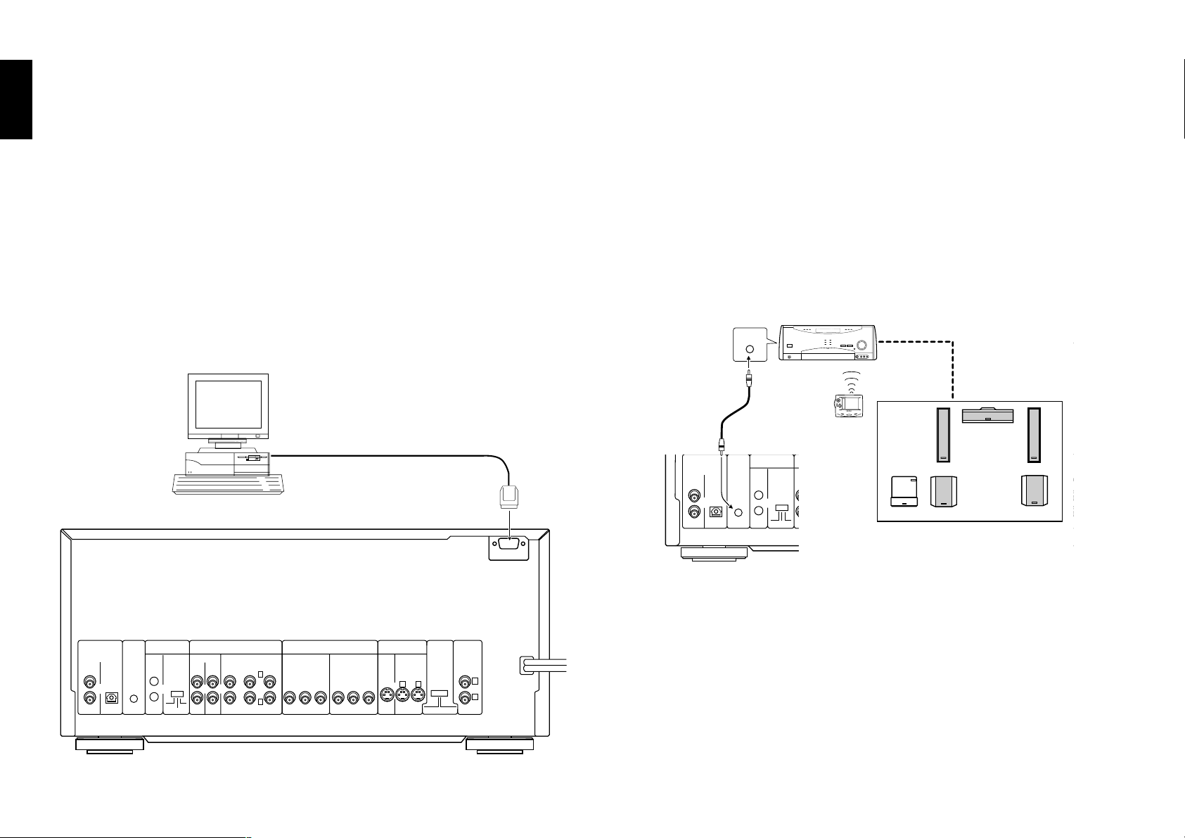
1-8 PC Link Connection
PC LINK function, which allows you to connect your PC to the DVD mega-changer
Chapter 1Chapter 2Chapter 3Chapter 4Chapter 5
and download disc titles and track data from an Internet site and register them in the
DVD mega-changer.
http://www.kenwoodusa.com
RS-232C cable(Reverse type)
(Provided)
1-9 DVD Control Function
(Except for DVF-J6050 Asia version)
The basic operations of this unit, such as playback and stop, can be remote controlled
from the LCD remote control unit provided with a KENWOOD AV receiver*.
÷ Connect the DVD control terminal of the AV receiver to the DVD CONTROL
terminal of this unit using a system control cable.
* The receiver should be equipped with the DVD control function.
DVD
CONTROL
System control cable
(Provided)
DIGITAL
(PCM/BIT STREAM)
COAXIAL
OPTICAL
IN
OUT
OUT
DVD
CONTROL
DAISY CHAIN
CONTROL
MAIN-SUB
SWITCH
MAIN
MIX LINE
INPUT OUTPUT FRONT SURROUND
SUB2
SUB1
AUDIO
6 CH. INPUT
CENTER
SUB WOOFER
COMPONENT VIDEO
INPUT INPUT
L
Y Cb Cr Y Cb Cr
R
S VIDEO
OUTPUT OUTPUT
COMPONENT
VIDEO
21
OUTPUT
INTE RLACE PROGRESSIVE
VID
OUT
Chapter 6
Chapter 7
Chapter 8
Illust Model : DV-5900M
20
DIGITAL
(PCM/BIT STREAM)
COAXIAL
OPTICAL
IN
OUT
OUT
DVD
CONTROL
DAISY CHAIN
CONTROL
MAIN-SUB
SWITCH
MAIN
RS-232C
CENTER
COMPONENT VIDEO
INPUT
YC
BCR
OUTPUT
YCBC
AUDIO
6 CH. OUTPUT
MIX LINE
INPUT OUTPUT
FRONT SURROUND
L
SUB2
SUB1
R
SUB WOOFER
S VIDEO
INPUT
OUTPUT
R
21
COMPONENT
VIDEO
OUTPUT
INTERLACE PROGRESSIVE
VIDEO
OUTPUT
1
2
Page 21

Chapter 2: Controls and indicators
Chapter 2: Controls and indicators
2-1 Introduction
This chapter gives description on the front panel buttons, display panel of the player main unit and the provided remote control unit.
This chapter is composed of the following sections.
Front Panel ................................................................ ™
Display ....................................................................... £
Standard Remote Control unit .................................¢
Keyboard Remote Control unit ................................ §
Chapter 1
Chapter 2
Chapter 3
Chapter 4
Chapter 5
21
21
Chapter 6
Chapter 7
Chapter 8
Page 22
Chapter 2: Controls and indicators
4
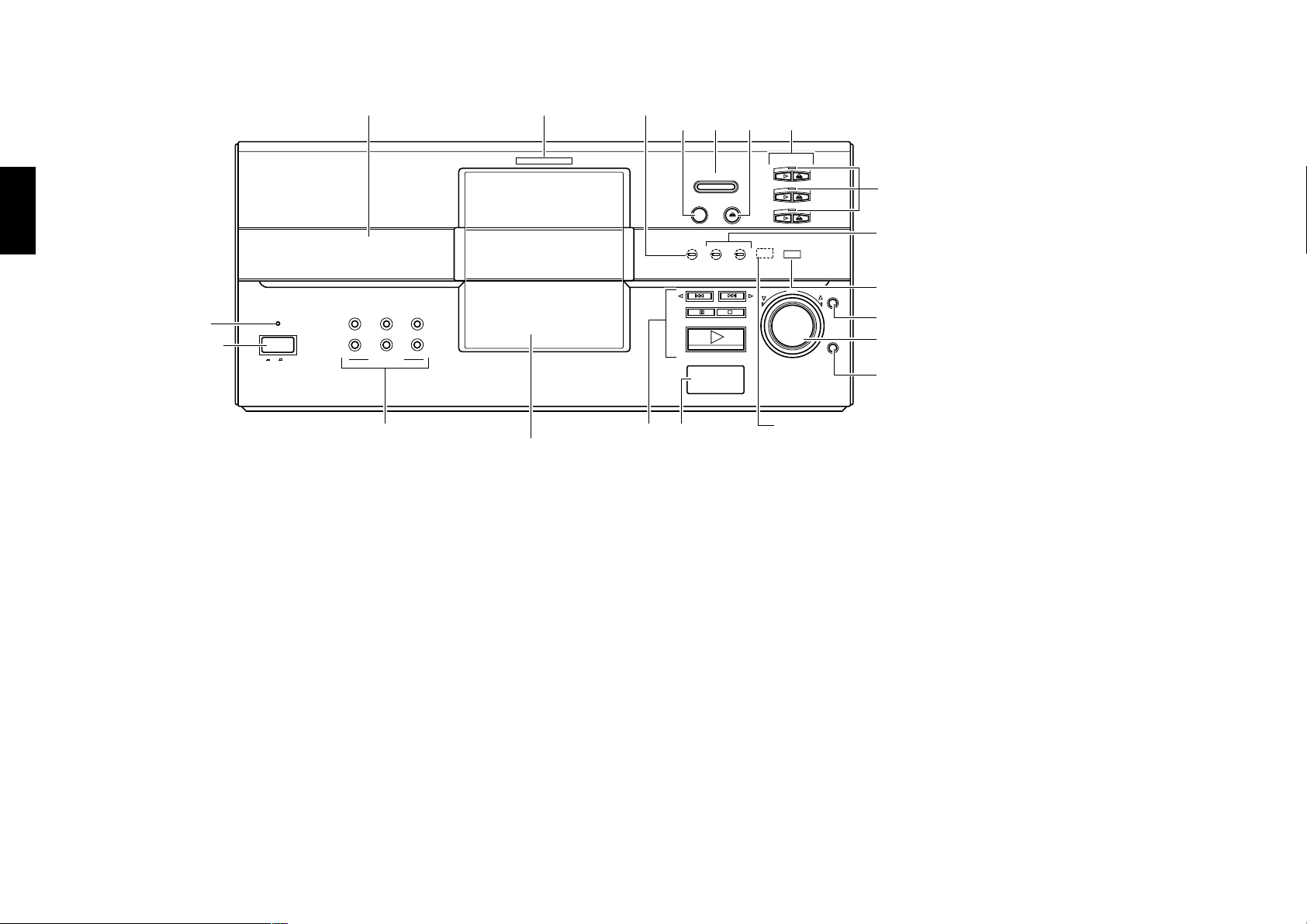
2-2 Front Panel
Display
Chapter 1Chapter 2Chapter 3Chapter 4Chapter 5
STANDBY indicator
5
STANDBY
POWER
ON OFF
TEXT DISPLAY TIME DISPLAY RANDOM
1 OPEN/CLOSE button ª
2 DISC FLIP button E
3 EJECT button ª
4 PLUS 1 3 (play), 0 (eject) button º
Chapter 6
Chapter 7
PLUS 2 3 (play), 0 (eject) button º
PLUS 3 3 (play), 0 (eject) button º
5 POWER button •
6 TEXT DISPLAY button Q
MUSIC TYPEUSER FILE SET
DISC SEARCH
6
DVD indicator
Disc door
VIRTUAL SURROUND indicator
1
23
PLUS
1
PLUS
2
PLUS
3
PURE AUDIO
DISC
Remote sensor
OPEN/CLOSE
VIRTUAL
SURROUND
78
DISC FLIP
EJECT
192kHzfs 96kHzfs
ENTER
USER FILE button Á
MUSIC TYPE button ˇ
SET button ˇÁ
7 4 button ⁄
Functions as the [cursor left] button in the LIBRARY
mode. ∏
¢ button ⁄
Functions as the [cursor right] button in the LIBRARY
mode. ∏
8 (pause, still) button ⁄
PLUS 1-3 indicator
Sampling indicators
DV-5900M (96kHz fs/192kHz fs)
Other (96kHz fs)
LIBRARY
PURE AUDIO indicator (DV-5900M only)
9
RETURN
0
!
8 LCD remote transmitter
The disc and track title data are output to the LCD
remote control unit (provided with a KENWOOD
Receiver or optional) through this window.
9 LIBRARY button Á
0 DISC knob ª
Functions as the [cursor up, down] button in the
LIBRARY mode. ∏
! RETURN button ∏
Functions as the [return] button in the LIBRARY
mode. Note that the function of the RETURN button
on the main unit is deactivated in the LIBRARY mode.
Chapter 8
22
TIME DISPLAY button fl
RANDOM button p
7 (stop) button ⁄
3 ENTER (play, enter) button º
Page 23
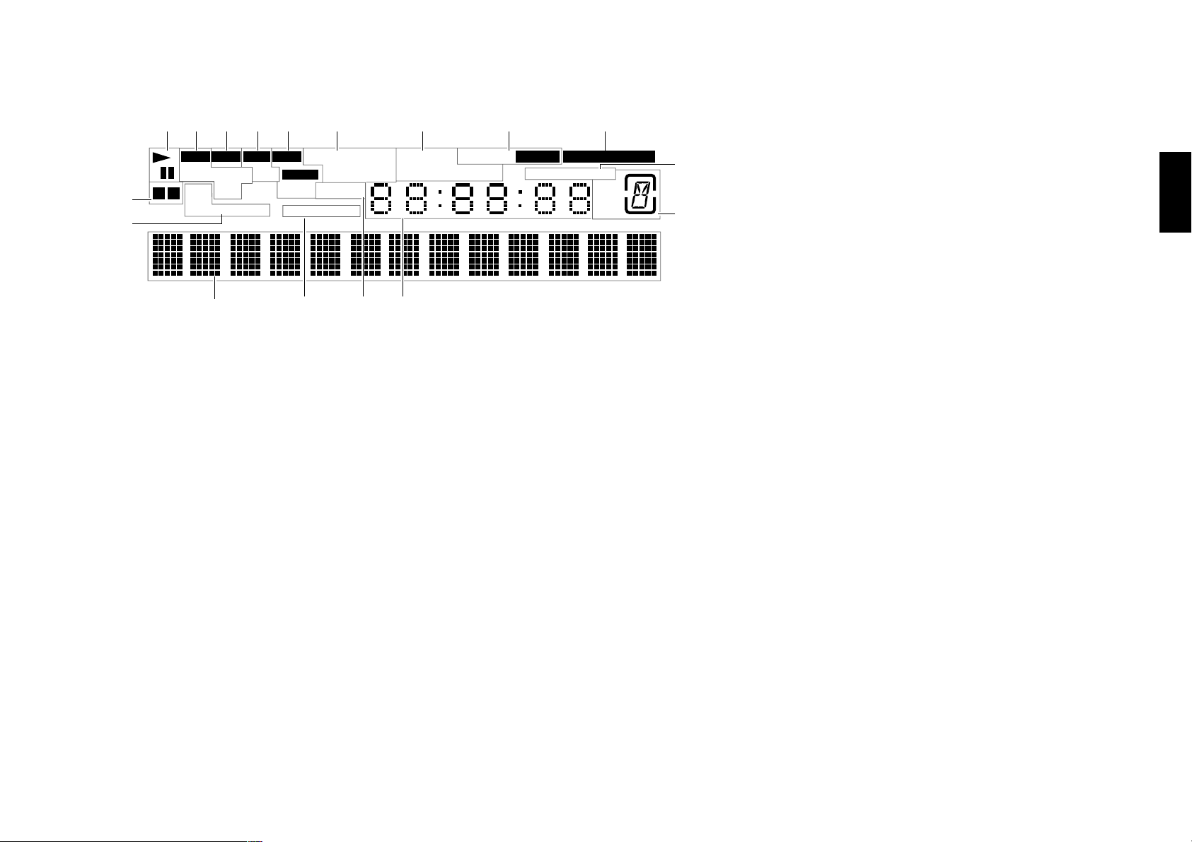
2-3 Display
Chapter 2: Controls and indicators
Chapter 1
2345 6 7 8
1
MP3 CD VCD DVD DOLBY DIGITAL RANDOM RELAY
FOLDER
P.B.C.
0
A B PGM
U.FILE M.TYPE
FILE
AUDIO
VIDEO
SEQUENTIAL
DTS MPEG REPEAT A 3 B TOTAL REMAIN
ANGLE
7
!@ $
1 Operation indicators
2 MP3 indicator
“MP3” lights during playback of an MP3 file.
3 CD indicator º
4 VCD related indicators ‹
5 DVD related indicators
“AUDIO” and “VIDEO” light only with the DV5900M.
#
9
ACTIVE PROGRESSIVE
$
MAIN
SUB
D.C.
9 PROGRESSIVE indicators $
0 DVD reverse mode related indicators E
! Character information display
@ SEQUENTIAL indicator ›
Lights in the Sequential mode.
# ANGLE indicator u
$ Time related indicators fl
8
2-3-1 Switching the Display Brightness
Press the DISP. button on the remote to switch the
display brightness in the following sequence.
"Brightness" : The display is permanently displayed
in high brightness.
"Dimmer" : The display is permanently displayed in
low brightness.
"Auto Off" :
The display status becomes as follows.
With a disc containing video, such as DVD or
VCD
During playback : Goes Off
During stop: “Brightness” status
Other operation than playback: “Brightness”
status for 3 seconds.
With a disc without video, such as CD or MP3
The display remains in the “Brightness” status.
"FL OFF" : The display is turned off.
Chapter 2
Chapter 3
Chapter 4
Chapter 5
Chapter 6
6 Decorder related indicators
7 Special playback related indicator ›wp
8 Daisy Chain function releted indicators W
23
23
Chapter 7
Chapter 8
Page 24

Chapter 2: Controls and indicators
2-4 Standard Remote Control Unit
The buttons with the same names as those on the player main unit have the same functions as the main unit buttons.
Chapter 1Chapter 2Chapter 3Chapter 4Chapter 5
For DV-5900M
1 Daisy Chain related buttons
MAIN button W
Chapter 6
Chapter 7
Chapter 8
1
2
3
4
5
6
7
8
9
0
!
@
SUB 1
MAIN
POWER
LIBRARY
TOP MENU
FOLDER
FILE
MP3
SEARCH
SEARCH
ENTER
¢
4
DISC SEL.
CHARAC.
UP/DOWN
DISC
RETURN
MODE
SET UP
DISC FLIP
1
DELETE
RANDOM REPEAT AUDIO
A - B .
D ' E ( F )
GH I J
123
KLM
456
OPQ
789
STU
+100 0 +10
WXY
7
8
SPACE
PLUS 1 PLUS 2 PLUS 3
DISP. TIME PGM
REMOTE CONTROL UNIT
RC-D0513
SUB 2
E
M
SET
3
¡
CHARAC.
C /
CHECK
CLEAR
N
PURE AUDIO
R
V
Z
O
N
S
C
R
E
E
N
P.B.C.
U
N
+
#
$
%
^
&
*
(
)
PAGESEQ.
SUB 1 button W
SUB 2 button W
2 LIBRARY button Á
3 Cursor buttons ‹°
4 TOP MENU button ‹
FOLDER SEARCH button ∏
5 ENTER button º‹
6 4, ¢ buttons ⁄‹
7 MODE button ªT
8 SET UP button Es
9 DISC FLIP button E
0 RANDOM button p
REPEAT button ›
AUDIO button fl
! PLUS 1 button º
PLUS 2 button º
PLUS 3 button º
CHECK button p
@ Numeric buttons º
# POWER button •
$ ON SCREEN button °
% MENU button ‹
FILE SEARCH button ∏
P.B.C. button ‹
^ DISC +, – (DISC up, down) buttons ª
& RETURN button ‹°
* SET button ª
( Basic operation related buttons
7 button ⁄
3 button º
1 button ¤
8 button ⁄
¡ button ¤
Character input operation related buttons
DELETE button P
SPACE button O
CHARAC. button O
) Characters and symbol buttons O
+100 button º
+10 button º
Special playback related buttons
DISC SEL. button º
DISP. button £
TIME button fl
PGM button o
CLEAR button p
PURE AUDIO button fl
SEQ. button ›
PAGE %, fi buttons ›
24
Page 25

The buttons with the same names as those on the player main unit have the same functions as the main unit buttons.
Chapter 2: Controls and indicators
Chapter 1
For DV-5050M/DVF-J6050
SUB 1
LIBRARY
MAIN
POWER
1
2
3
TOP MENU
FOLDER
FILE
MP3
SEARCH
4
5
6
¢
4
ENTER
CHARAC.
UP/DOWN
DISC
RETURN
SEARCH
7
MODE
8
9
0
!
@
SET UP
DISC FLIP
1
DELETE
RANDOM REPEAT AUDIO
A - B .
D ' E ( F )
DISC SEL.
GH I J
123
KLM
456
OPQ
789
STU
+100 0 +10
WXY
7
8
SPACE
PLUS 1 PLUS 2 PLUS 3
DISP. TIME PGM
REMOTE CONTROL UNIT
RC-D0512
SUB 2
SET
3
¡
CHARAC.
C /
CHECK
CLEAR
SEQ.
1 Daisy Chain related buttons
MAIN button W
SUB 1 button W
O
N
S
C
R
E
E
N
#
$
SUB 2 button W
2 LIBRARY button Á
3 Cursor buttons ‹°
4 TOP MENU button ‹
P.B.C.
U
N
E
M
%
FOLDER SEARCH button ∏
5 ENTER button º‹
+
^
6 4, ¢ buttons ⁄‹
7 MODE button ªT
&
*
8 SET UP button Es
9 DISC FLIP button E
(
0 RANDOM button p
REPEAT button ›
AUDIO button fl
)
N
R
V
Z
! PLUS 1 button º
PLUS 2 button º
PLUS 3 button º
CHECK button p
@ Numeric buttons º
% MENU button ‹
FILE SEARCH button ∏
P.B.C. button ‹
^ DISC +, – (DISC up, down) buttons ª
& RETURN button ‹°
* SET button ª
( Basic operation related buttons
7 button ⁄
3 button º
1 button ¤
8 button ⁄
¡ button ¤
Character input operation related buttons
DELETE button P
SPACE button O
CHARAC. button O
) Characters and symbol buttons O
+100 button º
+10 button º
Special playback related buttons
DISC SEL. button º
DISP. button £
TIME button fl
PGM button o
CLEAR button p
SEQ. button ›
Chapter 3
Chapter 4
Chapter 5
Chapter 6
Chapter 7
Chapter 8
# POWER button •
$ ON SCREEN button °
Chapter 2
25
25
Page 26
Chapter 2: Controls and indicators
,
REMOTE CONTROL UNIT RC-KB3
<
POWER
ALL DATA
READ
DISC FLIP
MENU
MAIN
ACTIVE
RETURN
SUB 1
ACTIVE
+10
SUB 2
ACTIVE
LIBRARY
TITLE
INPUT
(FL DISP.)
DISPLAY
ON SCREEN
TOP MENU
DELETE
+100
DISC
SEL
DISC
DOWN
DISC
UP
374¢
+
±
≠=
ENTER
SET
SHIFT
SHIFT
USER
FILE
NAME
SPACE
QWERTYUI OP
ASDFGHJKL
:
ZXCVBNM
>
/
?
.
,
,,
,
;
@
2
!
1
#
3
$
4
%
5
^
6
&
7
✱
8 9
0
-
+
=
()
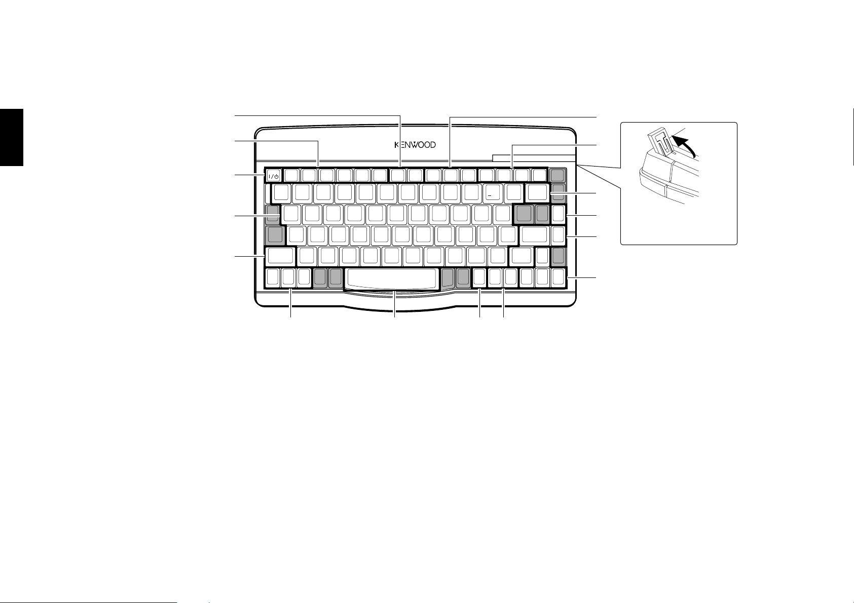
2-5 Keyboard Remote Control Unit (DV-5900M only)
The buttons with the same names as those on the player main unit have the same functions as the main unit buttons.
Chapter 1Chapter 2Chapter 3Chapter 4Chapter 5
1
2
3
4
5
1 +10 button º
+100 button º
2 DVD operation related buttons
Chapter 6
Chapter 7
Chapter 8
ALL DATA READ button ª
DISC FLIP button E
DISPLAY button £
ON SCREEN button °
TOP MENU button ‹
MENU button ‹
3 POWER button •
4 Character and symbol buttons O
0
!
@
#
Adjust the keyboard
height as required.
$
%
678
5 SHIFT button P
6 Daisy Chain related buttons
MAIN ACTIVE button W
SUB 1 ACTIVE button W
SUB 2 ACTIVE button W
7 SPACE button O
8 RETURN button ‹°
9 TITLE INPUT (FL DISP.) button „
LIBRALY button Á
0 Disc selection related buttons
DISC SEL button º
DISC DOWN button P
DISC UP button P
9
! Basic operation related button
4, ¢ buttons ⁄‹
3 button ¤
7 button ⁄
@ DELETE button P
# USER FILE NAME button P
$ Entry/setting related buttons
ENTER button º‹
SET button P
% Cursor buttons ‹°
26
Page 27

Chapter 3: Basic Operation
Chapter 3: Basic Operation
Chapter 3 : Basic Operation
3-1 Introduction
This chapter gives description on the basic operations of the control buttons on the player main unit and remote.
This chapter is composed of the following sections.
Configuration of Discs ............................... •
Turning power on ....................................... •
Inserting discs ............................................ ª
In regard to ALL DATA READ mode ............ ª
Operation restriction according to the disc or
player status................................................ º
Playing discs ............................................... º
PLUS1 to PLUS3 slots ................................. º
Playing discs by changing them.................. º
Playing from the selected disc .................... º
Switching the sequential play mode ........... ›
Repeat playback .......................................... ›
Switching the time display.......................... fl
Pure Audio function ................................... fl
Switching the audio language..................... fl
Chapter 1
Chapter 2
Chapter 3
Chapter 4
Chapter 5
Playing discs by selecting the title, chapter, track
or file .......................................................... ⁄
Skipping a track, chapter or file ................. ⁄
Stopping playback ...................................... ⁄
Still picture display and playback pause .... ⁄
Frame-by-frame advance ............................. ⁄
Forward search and reverse search............. ¤
Slow playback and reverse slow playback ... ¤
What is the “normal play TRACK mode”? ... ¤
Menu playback of DVD ............................... ‹
Menu playback of P.B.C.-compatible VCD .. ‹
Switching still pictures of DVD AUDIO ...... ›
Chapter 6
Chapter 7
Chapter 8
27
Page 28
Chapter 3: Basic Operation
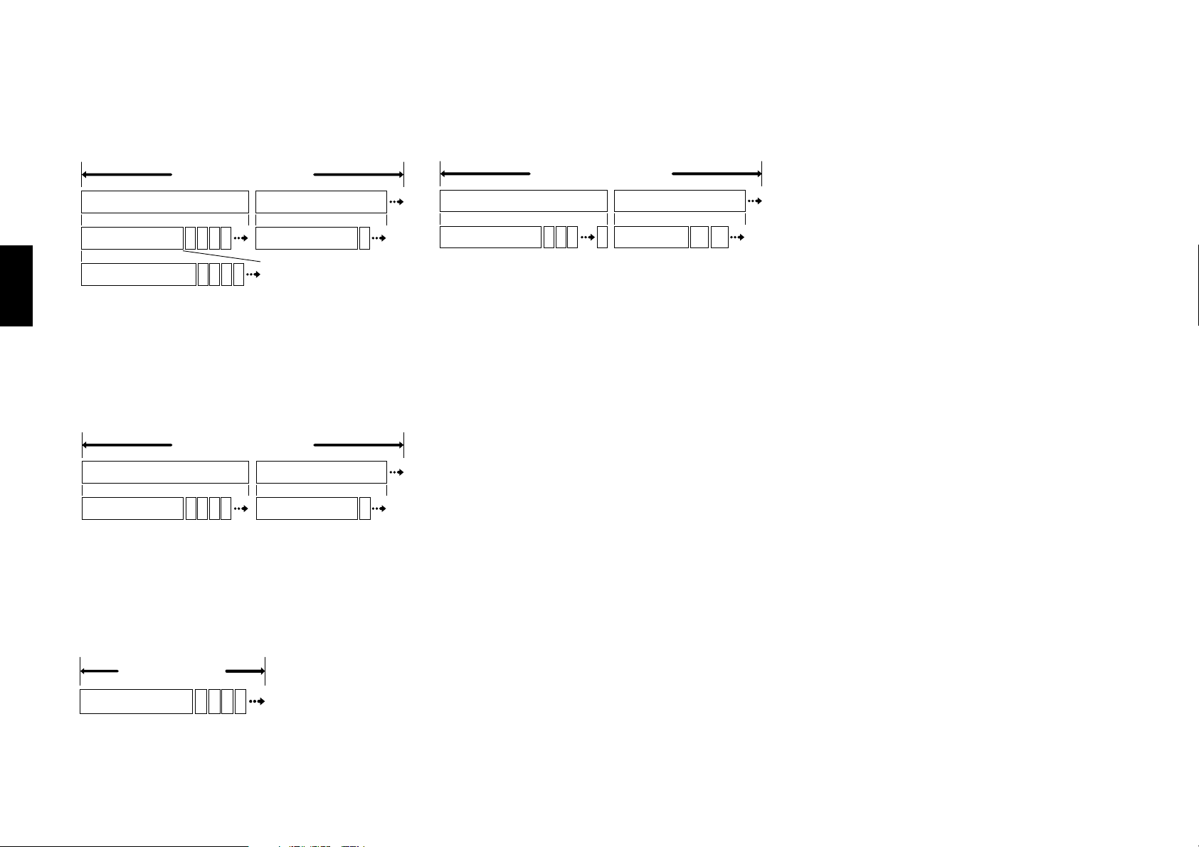
3-2 Configuration of Discs
Chapter 1Chapter 2Chapter 3Chapter 4Chapter 5
DVD AUDIO disc configuration (DV-5900M only)
DVD AUDIO
Group 1
Track 1
Index 1
22 3 4 5
22 3 4 5
The group is the largest unit composing the music
in an DVD AUDIO disc. Each group is composed
of multiple tracks, and each track is composed of
multiple indices.
DVD VIDEO disc configuration
DVD VIDEO
Title 1
Group 2
Track 1
Title 2
3-3 Turning power on
MP3 disc configuration
MP3
Folder 1
22
File 1
22 3 4 n 2n+3n+2
Folder 2
File n+1
Configuration of MP3 discs
The folder is the storage unit at the highest level in the
disc. Sometimes a single folder contains more than one
file, or sometimes files are recorded directly in the disc
in place of being included in a folder. Some discs also
have a hierarchical structure in which a folder includes
sub-folders. Note that the file numbers are not assigned
on a per-folder basis but they are assigned consecutively
for all the files in the whole disc.
Operation procedure
1. If preparation of the TV is required :
Set the input selector of the TV to monitor the video
output from this unit.
If preparation of the AV amplifier is required :
Set the input selector of the AV amplifier to monitor
the audio output from this unit.
2. Press the POWER button on the player.
When the power of the player is in the standby mode,
press the POWER button on the remote.
÷ When power is switched on, the unit starts
detection of discs in the stocker (“DETECTION” is
displayed during this).
When discs have been detected, the unit automatically
reads TOC on discs (“READING” is displayed during
this) then starts playback.
÷ When no disc has been detected, the display shows
“NO DISC”.
Chapter 1
22 3 4 5 22
The title is the largest unit composing the music
and/or pictures in an DVD VIDEO disc. Each title
Chapter 6
is composed of multiple chapters.
CD and VCD disc configuration
CD and VCD
Chapter 7
Track 1
Chapter 8
28
Chapter 1
[To put the player power in the standby mode]
÷ When the power is on, press the POWER button on the
remote. The "STANDBY" indicator lights up to indicate
that the player is in the standby mode of power.
[To turn the player off]
÷ When the power is on or standby, press the POWER
button on the player to turn it off.
22 3 4 5
Page 29
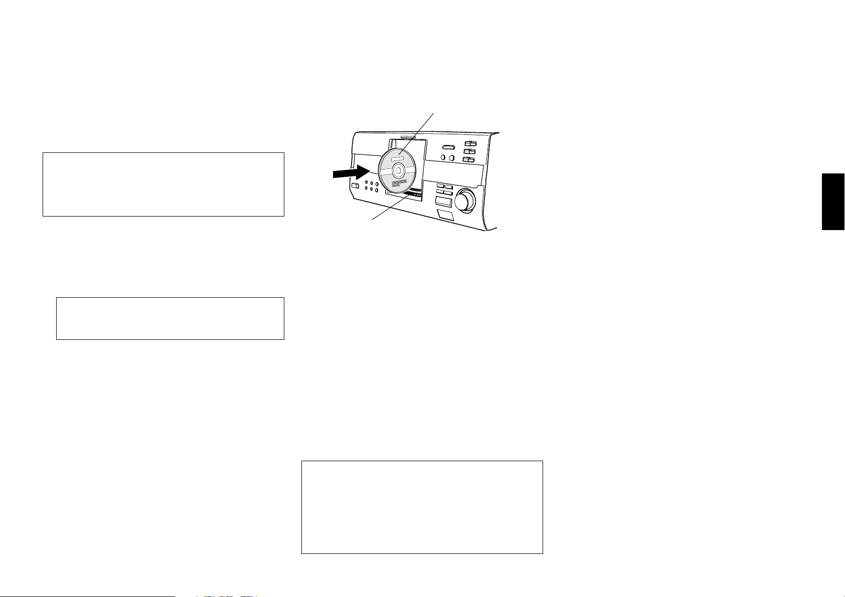
Chapter 3: Basic Operation
Chapter 1
3-4 Inserting discs
Up to 403 discs can be loaded in the stocker. Disc
exchange also is possible during playback.
The discs can be changed during playback without
stopping the currently played disc.
Be sure to operate a button when opening/closing
the disc door or rotating the stocker. Never
attempt to move the stocker with your hand.
Never let your hand or any object enter inside the
unit.
Operation procedure
1. Press the OPEN/CLOSE button on the player main
unit to open the disc door. (Pressing the button again
closes the disc door.)
This unit cannot play back 8 cm discs. Do not
attempt to play an 8 cm disc for this may result
in malfunction.
÷ Place the disc to be played along the groove on the
slot.
÷ Do not insert more than one disc in a slot.
÷ When handling a disc, take care not to touch the
disc surface.
3. Insert the disc vertically.
÷ Insert it so that the side to be played back faces
leftward.
disc label side
Stocker
4. Repeat 2 and 3 to insert discs.
5. Press the OPEN/CLOSE button on the player to close
the disc door.
÷ When the disc door closes :
The unit starts detection of discs in the stocker
(“DETECTION” is displayed during this).
Ejecting the disc
Operation procedure
1. Turn the DISC knob on the main unit to select a disc.
3-5 In regard to ALL DATA READ mode
The disc information for all discs will be read. We
recommend to execute this mode before playback after
discs have been exchanged.
Close the disc door before operation.
Operation procedure (remote)
1. Press the MODE button.
2. Press the DISC +(up), – (down) button, then select
“ALL DATA READ”.
3. Press the SET button.
÷ To display the title on a LCD remote control unit
(provided with a KENWOOD Receiver or optional),
perform the all data read operation first, and
operate the LCD remote control unit with the disc
door closed. For the operation of the LCD remote
control unit, refer to the instruction manual
provided with your receiver or LCD remote control
unit.
÷ If you are operating the keyboard remote, press the
ALL DATA READ button. (DV-5900M only)
÷ To quit ALL DATA READ mode, Press the 7 button.
Chapter 2
Chapter 3
Chapter 4
Chapter 5
Chapter 6
÷ Please do not use discs which are not round
because they may cause malfunction.
2. Turn the DISC knob and bring the slot with the disc
to be placed to the front.
÷ If you are operating the remote, press the DISC
+(up), – (down) button.
2. Press the EJECT 0 button.
When “REMOVE DXXX” is displayed :
A disc is inserted in the slot with the same disc number
as the disc being loaded. It is not permitted to insert
another disc in a slot from which the disc has been
loaded. Remove the inserted disc and insert it in an
idle slot.
Chapter 7
Chapter 8
29
Page 30

Chapter 3: Basic Operation
3-6 Operation restriction according to the disc or player status
Chapter 1Chapter 2Chapter 3Chapter 4Chapter 5
Operations of some DVDs and VCDs are restricted by
the intention of the software producers. Operations may
also be restricted due to the status of the player.
As this player plays discs in accordance with the
intentions of software producers, some functions may
not work as intended by the user. Be sure to read the
manual provided with the disc to be played. When an
inhibition icon is displayed on the connected TV screen
during operation, it indicates that the player is in the
operation restricted status.
Inhibition icon
3-7 Playing discs
Press the 3 button in stop mode to start playback.
÷ When you are operating the remote, press the 3
or ENTER button.
÷ The TV screen shows "Play" and the 3 indicator
in the display lights up.
Chapter 6
Chapter 7
Chapter 8
÷ The type of the disc being played is shown on the
display. £
÷ Certain CD-R and CD-RW discs may not be
playable on this player.
÷ The CD indicator lights when a CD-DA disc is
loaded.
÷ When a disc containing MP3 files is played, the
“MP3” indicator lights.
÷ When the loaded disc contains text data such as
the disc title, the text will be scrolled on the display
on this player.
“Registration of Title” Œ
÷ With certain DVD and VCD discs, a menu is
displayed in the beginning.
“Menu playback of DVD” ‹
“Menu playback of P.B.C.-compatible VCD”
‹
3-8 PLUS1 to PLUS3 slots
Unlike the discs in other 400 slots, the discs in these
slots can be played back by simply pressing the
button, without the need of setting or selecting the disc
number. Another feature of these slots is that they have
wider areas around the grooves to facilitate insertion and
ejection of discs.
Three PLUS slots, 1 to 3, are provided.
Operation procedure
1. Press the button button of one of the PLUS1 to
PLUS3 slots.
2. The PLUS slot selected in step 1 moves to the center
of the disc door, then the disc door opens.
3. Insert a disc. ª
4. Press the button button to start playing the disc.
÷ When if you are operating the remote, press the
PLUS 1 to PLUS 3 button.
÷ With the PLUS1 to PLUS3 slots, special playback
such as program playback and random playback
is not available.
3-9 Playing discs by changing them
Turn the DISC knob to skip a disc.
÷ When you are operating the remote, press the DISC
+(up), – (down) button.
÷ The DISC knob in the player is invalid when the
disc door is closed in the all random and program
modes.
÷ When the sequential play mode of the player is set
to "Sequential On", the DVD VIDEO is not played
back. ›
3-10 Playing from the selected disc
Operation procedure
1. Press the DISC SEL. button on the remote to select a
disc.
2. Compose the disc number to be played using the 0
to 9, +10 and +100 buttons.
No 253 ........... +100 x 2, +10 x 5, 3
No 120 ........... +100, +10 x 2, 0
3. Press the 3 button.
÷ The DISC SEL. button is invalid in the all random
and program play modes.
÷ When the sequential play mode of the player is set
to "Sequential On", the DVD VIDEO is not played
back. In this case, playback starts with track 1 of
the selected disc and continues on all other discs
in the stocker except for DVD VIDEO discs. ›
30
Page 31

Chapter 3: Basic Operation
Chapter 1
3-11 Playing discs by selecting the title, chapter, track or file.
Input the number of the title, chapter, track or file
using 0 to 9, +10 and +100 on the remote.
÷ With a DVD, when a number is input during
playback, playback of the chapter or track having
the same number as the input number in the same
group or title starts. When a number is input in
stop mode, playback the first chapter or track in
the group or title having the same number as the
input number starts.
÷ With a CD or VCD (when P.B.C. is off), playback
starts with the beginning of the track having the
same number as the input number.
÷ With a MP3 file, playback starts with the beginning
of the file having the same number as the input
number.
3-12 Skipping a track, chapter or file
Press the 4 or ¢ button on the player.
÷ A track is skipped and playback starts from the
beginning of the skip destination track, chapter or
file.
÷ When the 4 button is pressed once during playback,
playback restarts from the beginning of the current track,
chapter or file.
3-13 Stopping playback
Press the 7 button during playback. The first press
activates the resume function and the second press
stops playback.
÷ With certain DVDs, the inhibition icon is displayed
and playback cannot be stopped even when the 7
button is pressed. In this case, turn the DISC knob
to select another disc then press the 7 button to
stop playback.
If there is only one disc in the stocker, open the
disc door, place another disc, close the disc door,
turn the DISC knob to select the second disc, then
press the 7 button to stop playback.
÷ When you are operating the remote, press the 7
button.
÷ The resume function stores the position where
playback is stopped in memory. Later, playback
can be restarted from that position by pressing the
3 button.
÷ While the resume function is activated, the "3"
indicator in the display blinks and shows the time
of the stored position.
÷ The resume function cannot be activated during
random playback, MUSIC TYPE PLAY mode and
USER FILE PLAY mode.
3-14 Still picture display and playback pause
Press the 8 button during playback.
÷ This operation is not available with a MP3 disc.
(DV-5900M only)
÷ The TV screen shows "Pause" or "Still" and the 8
indicator in the display lights up.
÷ To restart normal playback, press the 3 button on
the player.
÷ When the "IPB Display" is set to On, the TV screen
shows "Still (I)", "Still (P)" or "Still (B)" with
every still picture. f
3-15 Frame-by-frame advance
While a still picture of DVD or VCD is displayed, press
the 8 button .
÷ The picture returns to still picture when the 8
button is released.
÷ The picture frame is advanced for the same number
of times as the button is pressed. Hold the button
when you want to advance picture frames
sequentially.
÷ To restart normal playback, press the 3 button on
the player.
÷ When the "IPB Display" is set to On, the TV screen
shows "Still (I)", "Still (P)" or "Still (B)" every
time the picture frame is advanced. f
Chapter 2
Chapter 3
Chapter 4
Chapter 5
Chapter 6
Chapter 7
÷ With a VCD and P.B.C. is on, these buttons function
as the 4 (Previous) and ¢ (Next) button.
Chapter 8
31
Page 32

Chapter 3: Basic Operation
3-16 Forward search and reverse search
Chapter 1Chapter 2Chapter 3Chapter 4Chapter 5
During playback, press the 1 or ¡ button on the
remote.
÷ This operation is not available with a MP3 disc.
(DV-5900M only)
÷ When OSD is displayed, pressing the ON SCREEN
button turns it off and shows the speed in place.
÷ The first press of the 1 or ¡ button starts
forward search or reverse search at the lowest speed
step. Each further press increase the speed up to
the fifth speed step.
The TV screen shows the speed as shown above.
The indicator varies according to the speed of the
forward search or reverse search.
The display of the player shows the time display or
"SEARCH >>" according to the status of the disc
and player.
Displayed during P.B.C. playback of VCD.
Displayed during playback of a DVD with
which the time is not displayed.
3-17 Slow playback and reverse slow playback
While a still picture is displayed, press the 1 or ¡
button on the remote.
÷ This operation is not available with a MP3 disc.
(DV-5900M only)
÷ When OSD is displayed, pressing the ON SCREEN
button turns it off and shows the speed in place.
÷ The first press of the 1 or ¡ button starts slow
playback or reverse slow playback at the lowest
speed step. Each further press increase the speed
up to the fifth speed step.
The TV screen shows the speed as shown above.
The indicator varies according to the speed of the
slow playback or reverse slow playback.
The display of the player shows the time display or
"SLOW >>" according to the status of the disc and
player.
Displayed during P.B.C. playback of VCD.
Displayed during playback of a DVD with
which the time is not displayed.
3-18 What is the “normal play TRACK
mode”?
Playback is made from the first track. The normal
playback mode is called TRACK mode.
To set the unit to the TRACK mode :
At the time of PGM mode : o
Press the PGM button.
At the time of MUSIC TYPE or USER FILE mode :
YU
Press the MODE button.
At the time of RANDOM mode : p
Press the RANDOM button.
÷ The "RANDOM" indicator turns off.
At the time of REPEAT mode : ›
Press the REPEAT button.
÷ The "REPEAT" indicator turns off.
Chapter 6
Chapter 7
Chapter 8
32
÷ To restart normal playback, press the 3 button on
the player.
÷ Video may be disturbed during forward search or
reverse search.
÷ When performing forward search with a VCD, DVD
VIDEO or DVD AUDIO containing video and
moving pictures (AVTT: Audio Video Title), the
audio output can be switched on or off only while
the search is at the lowest speed step. The audio is
muted in the second and later speed steps. “Audio
During Search” j
÷ To restart normal playback, press the 3 button on
the player.
÷ Audio is not output during slow playback or reverse
slow playback.
÷ Reverse slow playback is not available with VCD.
÷ Slow playback and reverse slow playback are not
available with CD (MP3) or DVD AUDIO
containing only still pictures and audio (AOTT:
Audio Only Title).
Page 33

Chapter 3: Basic Operation
Chapter 1
3-19 Menu playback of DVD
When a DVD containing the recording of the top menu
or menu is played, the top menu or menu is displayed.
These menus allow you to select the position you want
to play easily based on an interactive method. The
following operation procedure is the basic procedure.
The functions vary depending on certain softwares.
Operation procedure
1. Press the TOP MENU button to display the top menu.
÷ When the TOP MENU button is pressed again
while the top menu is displayed during playback,
the played position returns to the position where
the button was pressed for the first time and
playback restarts from there.
2. Select the scene to be played by pressing the cursor
button on the remote. (The scene may sometimes be
selected using the numeric buttons.)
3. Press the ENTER button to play the DVD from the
selected title.
÷ To display multiple menus sequentially, repeat
steps 2 and 3 above. If the menus are provided in a
hierarchical structure, this operation allows you to
move to the menus in the lower hierarchy level.
÷ The MENU button on the remote is pressed, the
menu is displayed. The operation is the same as
that of the top menu.
3-20 Menu playback of P.B.C.compatible VCD
When a P.B.C. (PlayBack Control) capable VCD is played
with P.B.C. on, the menu is displayed. Perform operation
according to the procedure indicated by the menu. (For
details on the operation method and control buttons,
refer to the manual provided with the played software.)
3-20-1 Hierarchical structure of VCD menus
When a P.B.C.-compatible VCD containing menus is
played and an item is selected in the displayed menu, a
menu with more detailed items may sometimes be
displayed. Such a structure in which multiple menus are
distributed in different levels and interconnected is
referred to as the hierarchical structure. In this structure,
the target scene can be reached by repeatedly selecting
items in multiple menus.
Example of hierarchical structure
PLAY
RETURN
SELECT
NEXT NEXT
PREVIOUS
PREVIOUS
To advance in the hierarchy: When an item is selected
in the menu using the ENTER (Select) button or
numeric buttons, you can advance to the menu at
the level immediately below the current level. When
the selected item is a [scene], the scene will be played
back.
To return in the hierarchy: You can return to the level
immediately above the current level every time you
press the RETURN button.
Hierarchy level 1
(Menu)
Hierarchy level 2
(Submenus)
Hierarchy level 3
(Scenes)
÷ When there are multiple menus (scenes) in a
hierarchy level, they can be switched over by
pressing the 4 (Previous) button or ¢ (Next)
button.
3-20-2 Main control buttons used in VCD
playback, and examples of indications
Indication on
software jacket
3 (Select) ENTER button
(Return) RETURN button
4 (Previous) 4 button
¢ (Next) ¢ button
÷ The indication on the jacket is variable depending
on the software.
sofu
Control button
on the player
3-20-3 Switching P.B.C. On and Off
÷ When there is a VCD in the played position of the
stocker and the player is in stop mode, press P.B.C.
button to switch P.B.C. on or off.
P.B.C. on: The TV screen shows "P.B.C. On" and the
P.B.C.-compatible VCD is played according to
P.B.C.
The "P.B.C." indicator in the display lights up.
P.B.C. off: The TV screen shows "P.B.C. Off" and the
P.B.C.-compatible VCD is played in normal
playback without P.B.C.
The "P.B.C." indicator in the display turns off.
÷ P.B.C. is switched off automatically when the
sequential play mode is set to "Sequential On" or
when the play mode is set to the program or
random mode. ›
Chapter 2
Chapter 3
Chapter 4
Chapter 5
Chapter 6
Chapter 7
Chapter 8
33
Page 34

Chapter 3: Basic Operation
3-21 Switching still pictures of DVD
AUDIO (DV-5900M only)
Chapter 1Chapter 2Chapter 3Chapter 4Chapter 5
When a DVD AUDIO (AOTT: Audio Only Title) disc
containing the recording of still pictures is played, the
still pictures can be displayed. (The operation may be
restricted with certain discs.)
To switch the still pictures, press the PAGE % or PAGE
fi button on the remote during playback.
÷ Press the RETURN button to switch to the home
still picture.
3-22 Switching the sequential play mode
The player is capable of sequential playback using the
400-disc stocker disc changer. If a DVD and/or VCD is
mixed in the discs to be played sequentially, the
sequential playback may stall in the middle while the
menu remains displayed. In such a case, switch the
sequential play mode of the player.
Operation procedure
1. Set the player to normal play mode (Track mode).
¤
÷ Set the player to stop mode.
2. Each press of SEQ. button switches the sequential
play mode of the player alternately.
÷ The “SEQUENTIAL” indicator lights.
÷ With a DVD AUDIO disc containing the recording
of menu, menu playback is not available.
÷ With a P.B.C.-compatible VCD, playback is
performed by switching P.B.C. automatically to off.
÷ When the sequential play mode is changed,
"Sequential Off" or "Sequential On" is displayed
on the TV screen.
3-23 Repeat playback
Repeat playback allows you to play the desired audio or
video repeatedly.
Operation procedure
Press the REPEAT button during playback to display the
"MAIN" OSD. Each further press of the button switches
the repeat icons as shown. q
÷ This function may be unavailable with certain discs.
÷ If the on-screen message or OSD is displayed
outside the TV screen when using a widescreen TV
or similar monitoring device, set the "OSD
Position" setting to "Cinema". f
÷ When the player is set to the repeat play mode, the
"REPEAT" indicator in the display lights up. The
character information display also shows the repeat
mode information for a few seconds.
÷ This operation is not available with a DVD with
which the elapsed play time information is not
displayed.
÷ Repeat playback may also be unavailable during
P.B.C. playback of VCD.
Set the sequential play mode of the player to "Sequential
On" using the remote as described below. The DVD
VIDEO playback will be skipped in order not to interrupt
Chapter 6
the sequential playback.
(The display shows "SKIP DVD-V" to indicate this.)
(The display shows "SKIP DVD" to indicate this.)
Chapter 7
When playing a VCD with menu playback or playing a
DVD VIDEO, set the sequential play mode of the player
to "Sequential Off".
Chapter 8
34
(DV-5900M)
(Other)
Page 35

Chapter 3: Basic Operation
Chapter 1
3-23-1 OSD icons that can be selected with each
disc type and mode
[
During playback of DVD AUDIO
(DV-5900M only)
: Repeat playback of the track being played.
Trk
: Repeat playback of the group being played.
Grp
: Repeat playback of the disc being played.
Disc
÷ "Disc" is displayed only when "SEQUENTIAL"
indicator is lit.
: Repeat playback Off.
Off
[
During playback of DVD VIDEO
: Repeat playback of the chapter being played.
Chp
: Repeat playback of the title being played.
Ti
: Repeat playback Off.
Off
]
]
[During playback of MP3]
: Repeat playback of the file being played.
File
: Repeat playback of the folder being played.
Folder
: Repeat playback of the disc being played.
Disc
: Repeat playback Off.
Off
[In the program mode]
: Repeat playback of programmed contents.
Pgm
: Repeat playback Off.
Off
[In the random mode]
: Repeat playback according to the current random play
Rnd
mode.
: Repeat playback Off.
Off
o
p
[In the MUSIC TYPE mode]
During play
: Repeat playback of the track being played.
Trk
: Repeat playback of the disc being played.
Disc
: Repeat playback of music type contents.
M.Typ
: Repeat playback Off.
Off
During stop
: Repeat playback of music type contents.
M.Typ
: Repeat playback Off.
Off
[In the USER FILE mode]
During play
: Repeat playback of the track being played.
Trk
: Repeat playback of the disc being played.
Disc
Y
Chapter 2
Chapter 3
Chapter 4
Chapter 5
I
Chapter 6
[
During playback of CD or VCD
: Repeat playback of the track being played.
Trk
: Repeat playback of the disc being played.
Disc
: Repeat playback Off.
Off
: Repeat playback of user file contents.
]
User
: Repeat playback Off.
Off
Chapter 7
During stop
: Repeat playback of user file contents.
User
Chapter 8
: Repeat playback Off.
Off
35
Page 36

Chapter 3: Basic Operation
3-24 Switching the time display
The information in the time display can be switched over.
Chapter 1Chapter 2Chapter 3Chapter 4Chapter 5
(The information can also be switched by the OSD
operation. ‚)
This operation is not available in stop mode, during
menu playback of DVD or with a DVD for which time
display is disabled.
If P.B.C. is set to On with a VCD, set P.B.C. to Off.‹
Press the TIME DISPLAY button during playback to
display the "MAIN" OSD. Each further press of the
button changes the time display icons as shown below.
"Single Time": Elapsed play time of a track,
chapter or file.
"Single Remain Time": Remaining time in a
track, chapter or file.
"Total Time": Elapsed play time of a disc,
group or title.
"Total Remain Time": Remaining time in a
disc, group or title.
Chapter 6
Chapter 7
SINGLE
1: 3 0
SINGLE
12-:30
TOTAL
28: 5 0
TOTAL
45-:50
÷ If you are operating the remote, press the TIME
button.
÷ If the on-screen message or OSD is displayed
outside the TV screen when using a widescreen TV
or similar monitoring device, set the "OSD
Position" setting to "Cinema". f
÷ In the program or random play mode, only "Single
Time" and "Single Remain Time" can be switched
over.
3-25 Pure Audio function (DV-5900M only)
It blocks the video signal to prevent interference between
the video and audio signals so pure audio can be
reproduced by switching the Pure Audio function On.
When the video signal is blocked, the TV screen shows
no picture during audio playback.
Press the PURE AUDIO button on the remote to
switch the Pure Audio function on/off.
÷ When the Pure Audio function is activated, the
PURE AUDIO indicator lights up. Pressing the
button again switches the Pure Audio function off
and turns the indicator off.
÷ When an operation for displaying the on-screen
message (the display of the performed operation
contents on the TV screen) or OSD is performed,
the video signal is output temporarily.
÷ With some DVD and VCD discs, the menu may be
displayed.
3-26 Switching the audio language
When a VCD or a DVD containing the recording of audio
in multiple languages is played, the language used in the
voice can be switched over. (The audio language can also
be switched by the OSD operation. e)
Press the AUDIO button during playback to display
the "SOUND" OSD. Each further press of the button
switches the displayed
÷ If the on-screen message or OSD is displayed
outside the TV screen when using a widescreen TV
or similar monitoring device, set the "OSD
Position" setting to "Cinema". f
÷ With a DVD AUDIO disc, an audio language
number can be selected from up to 2 numbers.
÷ With a DVD VIDEO disc, an audio language
number can be selected from up to 8 numbers.
÷ With VCD, "Stereo", "L", "R" or "L+R" can be
selected.
÷ The default audio language set by the user is
selected when the power is turned on or the disc is
changed. If the default language is not contained
in the disc, the priority language defined for the
disc will be played back.
÷ The above operation is not available in stop mode.
It is also unavailable with ordinary music CDs (CDR, CD-RW).
1 Dolby
ENG 5.1ch
(Audio icon).
Chapter 8
36
÷ With a MP3 file, only the "Single Time" information
is displayed.
Page 37

Chapter 4: OSD Operation
Chapter 4 : OSD Operation
4-1 Introduction
The operations described in this chapter allows the user to perform operations and settings by referring to the OSD (On-Screen Display). As the OSD operation uses only the
specific buttons on the remote, the user can enjoy the functions of the player even before memorizing the functions of all buttons.
This chapter is composed of the following sections.
Basic OSD Operation ............................................... °
"MAIN" OSD Operation ............................................ ·
"SOUND" OSD Operation ........................................ e
"VISUAL" OSD Operation......................................... t
÷ If the on-screen message or OSD is displayed outside the TV screen when using a widescreen TV or similar
monitoring device, set the "OSD Position" setting to "Cinema". f
Chapter 1
Chapter 2
Chapter 3
Chapter 4
Chapter 5
÷ The OSD cannot be displayed when DVD is played by menu playback. It may also be unavailable with certain
discs.
÷ The "SOUND" OSD and "VISUAL" OSD can be displayed only in a play mode.
Chapter 6
Chapter 7
Chapter 8
37
Page 38

Chapter 4: OSD Operation
4-2 Basic OSD Operation
Various operations can be performed by selecting the
Chapter 1Chapter 2Chapter 3Chapter 4Chapter 5
OSD icons on the TV screen using the cursor button on
the remote.
Operation procedure
1. Press the ON SCREEN button to display OSD.
"MAIN" OSD :
Chapter
Title
Chapter 6
Chapter 7
Chapter 8
MAIN
Disc
5
3
3
Only the "MAIN" OSD can be displayed when the button
is pressed in stop mode. (The up and down arrows shown
in the above figure are not displayed.)
When the button is pressed in a play mode, the OSD
can be changed by pressing the cursor up/down button.
"SOUND" OSD :
1 Dolby
SOUND
ENG 5.1ch
"VISUAL" OSD :
VISUAL
1 ENG
÷ If the on-screen message or OSD is displayed
outside the TV screen when using a widescreen TV
or similar monitoring device, set the "OSD
Position" setting to "Cinema". f
TOTAL
28-: 4 0 Play Set
Off
Interace
Off
Progressive
Off
Scan
Off
(DV-5900M)
(DV-5900M)
1
(DV-5900M)
2. Select an OSD icon by pressing the cursor up/down
button, then press the ENTER button to display the
pull-down menu.
÷ Press the cursor button to move the cursor. But the
cursor cannot be moved to the icons of currently
unavailable functions.
÷ The OSD includes icons with a variety of functions.
The displayed icons are variable depending on the
player status and played disc.
EXIT
÷ When the cursor is located on the left or right end,
if you attempt to move the cursor toward the
outside, the cursor will move to the opposite end.
÷ To clear the OSD display, move the cursor to the
EXIT icon and press the ENTER button. (The same
effect can also be obtained by pressing the ON
SCREEN button.)
3. From the displayed pull-down menu, select the
desired item by pressing cursor button up/down
button or by inputting the desired item number using
0 to 9 , +10 and +100 button.
EXIT
Example of pull-down menu display:
Title
Chapter
3
TOTAL
3
1
2
3
4
5
28-: 4 0 Play Set
(DV-5900M)
EXIT
MAIN
Disc
5
Off
Example of menu display when a number is input:
Title
Disc
5
MAIN
When a group, title, chapter, track, folder, or file number is input
using numeric buttons, the pull-down menu display changes and
the input number blinks in it. (The figure on the right of the
input number shows the number of chapters in the disc.)
If you commit a mistake in the numeric button input, press
the RETURN button and restart the input from the beginning.
Chapter
3
2 34
-
TOTAL
3
|
28-: 4 0 Play Set
(DV-5900M)
÷ When 5 and ∞ are displayed on the top and
bottom of the pull-down menu, the menu has
more pages above or below the current page. When
the cursor is located on the bottom edge, press the
cursor down button makes it possible to advance
to the next page. (When the cursor is located on
the top edge, press the cursor upward makes it
possible to return to the previous page.)
÷ " " and " " on the left and right edges of pull-
down menu indicates that pressing the cursor
button makes it possible to clear the pull-down
menu and move the cursor to the originally pressed
icon. (The same effect is also available by pressing
EXIT
the RETURN button.)
4. Press the ENTER button to enter the selection in
memory.
÷ The OSD icon display varies depending on the
content of change.
EXIT
Off
38
Page 39

4-3 "MAIN" OSD Operation
This section describes the display contents and
controllable items of the "MAIN" OSD. (Note that
certain items may not be controllable depending on the
played disc and player status.)
Chapter
Title
MAIN
Disc
5
3
3
21 3 4 5
1 Disc icon: Shows the disc number. Select to change
the disc.
2 Group icon: Shows the group number in DVD AU-
DIO disc. (DV-5900M only)
Track icon: Shows the track number in DVD AUDIO, VCD or CD disc.
Title icon: Shows the title number in DVD VIDEO
disc.
Chapter icon: Shows the chapter number in DVD
VIDEO disc.
Folder icon: Shows the folder number in MP3 file.
File icon: Shows the file number in MP3 file.
Select an icon to change its content.
3 Time display icon: Shows the disc time. Select to
perform time search or change the time display.
4 Memory Play/Memory Set icon: Select to register
or recall memory. ‚
5 Repeat icon: Shows the repeat mode. Select to use
repeat play mode. q
TOTAL
28-: 4 0 Play Set
(DV-5900M)
Off
‚
4-3-1 Selecting the disc to be played
Use the following procedure to select a new disc to be
played using OSD.
÷ Rotate the DISC knob on the front panel to select
the disc number. The disc number can also be
EXIT
selected using the DISC SEL. and numeric buttons
on the remote.
Operation procedure
1. Press the ON SCREEN button to display the "MAIN"
OSD.
2. Move the cursor to the
Disc
(Disc icon) by pressing
5
the cursor left/right button, then press the ENTER
button.
÷ This operation is not available in the all random
and program mode.
3. Select the disc number (1~400, PLUS1~3) by pressing
the cursor up/down button, then press the ENTER
button to start playback.
1
2
3
The cursor is displayed on the currently selected disc
4
number.
5
÷ The disc number can be selected directly by using
the numeric buttons.
Chapter 4: OSD Operation
4-3-2 Selecting a group, title, folder, chapter,
track or file
Use the following procedure to select a new group, title,
folder, chapter, track or file to be played using OSD. (They
can also be selected directly by pressing the numeric
buttons or a 4, ¢ button. ⁄)
When performing this operation with a P.B.C.compatible VCD, set P.B.C. to off. ‹
Operation procedure
1. Press the ON SCREEN button during playback to
display the "MAIN" OSD.
2. Move the cursor to the "Group", "Track", "Title",
"Chapter", "Folder" or "File" icon by pressing the
cursor left/right button, then press the ENTER button.
DVD AUDIO (DV-5900M only) :
Select
Group
DVD VIDEO: Select
CD, VCD : Select
MP3 : Select
Track
or
3
Folder
3
Title
Track
3
File
or
3
Chapter
or
3
3
3
Chapter 1
Chapter 2
Chapter 3
Chapter 4
Chapter 5
Chapter 6
Chapter 7
Chapter 8
39
Page 40

Chapter 4: OSD Operation
3. Select the number by pressing the cursor up/down
Chapter 1Chapter 2Chapter 3Chapter 4Chapter 5
button, then press the ENTER button to start playback.
1
2
3
4
5
During playback, the cursor is located on the current
group, title, folder, chapter, track or file number. (In
this figure, the last number can be displayed by
pressing the cursor up button.)
The number can also be selected by composing the
number with numeric buttons on the remote.
÷ Only the title or group icon can be selected in stop
mode of DVD.
4-3-3 Time display switching and time search
Use the following procedure to switch the type of
information shown by the time display shown in the
OSD or player display. Time search is also available
for specifying the position to start playback by
inputting the time information. (The time display
information type can also be changed using the TIME
button.)
Time search is not available in stop mode, during menu
playback of a DVD or with a DVD VIDEO which does not
provide the time display.
When performing this operation with a P.B.C.-
Chapter 6
compatible VCD, set P.B.C. to off. ‹
÷ This operation is not available with a MP3 file.
2. Move the cursor to
TOTAL
28: 5 0
(Time Display icon)
by pressing the cursor left/right button, then press
the ENTER button.
3. Select the type of time display information by pressing
the cursor up/down button, then press the ENTER
button.
If time search is required, move the cursor to the time
display icon to select the type of time display
information, then perform the operations in step 4.
: - - : -
Single Time
- -
Single Remain Time
Total Time
Total Remain Time
÷ In the program or random play mode, only "Single
Time" and "Single Remain Time" can be switched
over.
÷ The time display icon in the OSD and the time
display in the player display varies according to the
change.
÷ When "Total Time" or "Total Remain Time" is
selected, the "TOTAL" indicator in the display light
up.
-
Input examples:
1 hr. 05 min. 00 sec. (with a DVD):
1, 0, 5, 0, 0
65 min. 00 sec. (with a CD or VCD):
6, 5, 0, 0
1 min. 28 sec.:
1, 2, 8
÷ If you commit a mistake in the numeric button
input, press the RETURN button and restart the
input from the beginning.
4-3-4 Memory playback
When you register a scene you like in memory, you can
start playback from that scene any time you want. Up to
10 scenes can be registered in memory.
Memory registration and deletion are not available
during menu playback of DVD or with a DVD VIDEO
for which time display is disabled.
When performing this operation with a P.B.C.compatible VCD, set P.B.C. to off. ‹
÷ This function may be unavailable with certain discs.
÷ This operation is not available with a MP3 file.
Chapter 7
Operation procedure
1. Press the ON SCREEN button during playback to
display the "MAIN" OSD.
Chapter 8
40
4. Input the time to start playback using 0 to 9, then
press the ENTER button.
a : Registering a scene in memory
Operation procedure
1. Press the ON SCREEN button during playback to
display the "MAIN" OSD.
Page 41

Chapter 4: OSD Operation
Chapter 1
2. Move the cursor to
(Memory Set icon) by
Set
pressing the cursor button left/right, then press the
ENTER button.
3. Select the memory number to be used in registration
by pressing the cursor up/down button, then press
the ENTER button when the scene to be registered
comes.
Ti/Grp/Trk
Disc
1
4
2
-
3
-
4
-
Time
1 1
0 : 0 8 : 2 8
- -
- -
: - - : -
-
- : - - : -
-
-
-
- : - - : -
-
-
÷ The displayed time value is the accumulated count
since second 0 of the first track in the same group.
÷ To cancel memory function, press the RETURN
button.
÷ Up to 10 scenes can be registered in memory.
÷ When a number in which a scene has already been
registered is selected, the scene will overwrite the
existing memory.
÷ The memory is cleared when the disc is changed
or the disc is reversed with the DISC FLIP function.
The memory numbers in which
scenes have already been registered
-
show the disc number, title, group,
-
folder, track or file number and the
-
time. Memory numbers 5 to 10 are
displayed on the next display page.
(DVD Audio/DV-5900M only)
ºE
b : Recalling memory
Operation procedure
1. Press the ON SCREEN button to display the "MAIN"
OSD.
2. Move the cursor to
Play
(Memory Play icon) and
press the ENTER button.
3. Select the memory number of the scene to be recalled
by pressing the cursor up/down button, then press
the ENTER button.
4-3-5 Repeat playback
(The same effect can also be obtained directly by
pressing the REPEAT button.)
÷ This function may be unavailable with certain discs.
Operation procedure
1. Press the ON SCREEN button during playback to
display the "MAIN" OSD.
2. Move the cursor to
(Repeat icon) by pressing
Off
the cursor left/right button, then press the ENTER
button.
3. Select the repeat mode by pressing the cursor up/
down button, then press the ENTER button.
÷ When the repeat mode is changed, the repeat icon
varies according to the change. When the player is
set to a repeat play mode, the "REPEAT" indicator
in the display lights up and the character
information display also shows the repeat mode
information for a few seconds.
÷ This operation is not available with a DVD with
which the elapsed play time information is not
displayed.
÷ Repeat playback may also sometimes be
unavailable during P.B.C. playback of VCD.
a : OSD icons that can be selected with each
disc type and mode
[
During playback of DVD AUDIO] (DV-5900M only)
Off
Track
Group
[During playback of DVD VIDEO]
Off
Chapter
Title
"Off": Repeat playback off.
"Track": Repeat playback of the track being
played.
BA
"Group": Repeat playback of the group being
played.
"A": A-B repeat playback. w
÷ "Disc" is displayed only when
"SEQUENTIAL" indicator is lit.
"Off": Repeat playback off.
"Chapter": Repeat playback of the chapter being
played.
BA
"Title": Repeat playback of the title being played.
"A": A-B repeat playback. w
Chapter 2
Chapter 3
Chapter 4
Chapter 5
Chapter 6
Chapter 7
Chapter 8
41
Page 42

Chapter 4: OSD Operation
Chapter 1Chapter 2Chapter 3Chapter 4Chapter 5
Chapter 6
Chapter 7
[During playback of CD or VCD
Off
Track
Disc
"Off": Repeat playback off.
"Track": Repeat playback of the track being played.
"Disc": Repeat playback of the disc being played.
BA
"A": A-B repeat playback. w
[During playback of MP3]
Off
File
Folder
Disc
"Off": Repeat playback off.
"File": Repeat playback of the file being played.
"Folder": Repeat playback of the folder being
played.
"Disc": Repeat playback of the disc being
played.
[In the program mode]
Off
Program
"Off": Repeat playback off.
"Program": Repeat playback of programmed
contents.
[In the random mode]
Off
Random
"Off": Repeat playback Off.
"Random": Repeat playback according to the
current random play mode.
]
[In the MUSIC TYPE mode]
Off
Track
Disc
M.Type
A B
During playback
"Off": Repeat playback off.
"Track": Repeat playback of the track being played.
"Disc": Repeat playback of the disc being played.
"M.Type": Repeat playback of music type contents.
"A": A-B repeat playback. w
During stop
"Off": Repeat playback off.
"M.Type": Repeat playback of music type contents.
Y
4-3-6 A-B repeat playback
A-B repeat playback allows you to play a specified
section repeatedly.
÷ This function may be unavailable with certain discs.
÷ This operation is not available with a MP3 file.
Operation procedure
1. Perform the repeat playback procedure steps 1. and 2.
q
2. Select "A" by pressing the cursor up/down button,
then press the ENTER button. The current disc position is stored in memory as point A where the
repeat playback is to be started and the cursor is
moved to "B".
[In the USER FILE mode]
I
÷ The Repeat icon changes to "A" and the "REPEAT"
o
Off
Track
Disc
User
A B
During playback
"Off": Repeat playback off.
"Track": Repeat playback of the track being played.
"Disc": Repeat playback of the disc being played.
"User": Repeat playback of user file contents.
"A": A-B repeat playback. w
During stop
"Off": Repeat playback off.
"User": Repeat playback of user file contents.
and "A 3" indicators in the display light up.
3. When point B where you want to stop repeat playback
comes, press the ENTER button again. Repeat playback
of the section between points A and B starts.
÷ The Repeat icon changes to "A B" and the
"REPEAT" and "A 3 B" indicators light in the
display.
÷ To cancel repeat playback, select "Off".
÷ This operation is not available during P.B.C.
playback of a VCD or with a DVD disc without time
p
display.
÷ This operation is not available in the all random
and program mode.
÷ A-B Repeat playback can be used only within a
same title. (DVD Video)
Chapter 8
42
÷ A-B Repeat playback can be used only within a
same track. (DVD Audio/DV-5900M only)
Page 43

4-4 "SOUND" OSD Operation
This section describes the items which can be controlled
with the "SOUND" OSD. (Some items may be
uncontrollable depending on the played disc and player
status.)
1 Dolby
SOUND
1
Audio icon: Shows the audio signal, audio language
and audio language No., number of audio channels.
Select to switch the audio language.
ENG 5.1ch
Off
1 2 3 4
Off
Off
(DV-5900M)
4-4-1 Switching the audio language
When a VCD or a DVD containing the recording of audio
in multiple languages is played, the language used in the
voice can be switched over. (The audio language can also
be switched directly by pressing the AUDIO button.)
Operation procedure
EXIT
1. Press the ON SCREEN button during DVD playback
and select the "SOUND" OSD by pressing the cursor
up/down button.
2. Move the cursor to
pressing the cursor left/right button, then press the
ENTER button.
1 Dolby
ENG 5.1ch
(Audio icon) by
Chapter 4: OSD Operation
4-4-2 Virtual Surround function
When playing a DVD recorded with Dolby Digital
Surround audio, powerful sound can be reproduced even
when you use only two speakers.
Operation procedure
1. Press the ON SCREEN button during DVD playback,
and select the "SOUND" OSD by pressing the cursor
up/down button.
2. Move the cursor to
by pressing the cursor left/right button, then press
the ENTER button.
(Virtual Surround icon)
Off
Chapter 1
Chapter 2
Chapter 3
Chapter 4
2
Virtual Surround icon: Shows the level of the Virtual Surround effect. Select to adjust the level of Virtual Surround or switch it off.
3
Cinema voice icon: Shows the on/off status of Cinema Voice. Select to switch Cinema Voice on or off.
4
Down Mix icon (DV-5900M only): Shows the on/
off status of Down mix. Select to switch Down Mix
on or off. r
r
3. Select the desired audio language number by pressing
the cursor up/down button, then press the ENTER
button.
÷ With a DVD AUDIO disc, an audio language
number can be selected.
1 P. PCM
5.1ch 96k 24b
÷ With a DVD VIDEO disc, an audio language
number can be selected from up to 8 numbers.
÷ With VCD, "Stereo", "L", "R" or "L+R" can be
selected.
÷ The default audio language set by the user is
selected when the power is turned on or the disc is
changed. If the default language is not contained
in the disc, the priority language defined for the
disc will be played back.
(DV-5900M only)
÷ The icon can be selected only when the played
software is recorded in Dolby Digital audio (with
2 or more channels).
3. Select the level of Virtual Surround effect by pressing
the cursor up/down button, then press the ENTER
button.
DV-5900M
Off
1
2
HP1
HP2
Other
Off
1
2
The effect is increased when the
selected level is higher. Select "Off"
to switch the effect Off. To select
the level of the Virtual Surround
effect through headphones, select
"HP VSS1" or "HP VSS2".
The effect is increased when the
selected level is higher. Select "Off"
to switch the effect Off.
Chapter 5
Chapter 6
Chapter 7
Chapter 8
43
Page 44

Chapter 4: OSD Operation
÷ When a DVD recorded with Dolby Digital audio
Chapter 1Chapter 2Chapter 3Chapter 4Chapter 5
(with 2 or more channels) is played, the "DOLBY
DIGITAL" indicator on the player main unit lights
up.
4-4-3 Cinema Voice function
This function to be used when words are hard to be
distinguished during playback of DVD recorded with
Dolby Digital Surround, Dolby Digital, DTS, or DVD
AUDIO* LPCM.
To use this function, it is required that the disc being
played provides the center channel audio.
*DVD AUDIO is DV-5900M only
÷ When the digital output terminal is used, the
“Digital Audio” setting should be set to “PCM”
or “Off”. h
Operation procedure
1. Press the ON SCREEN button during playback of DVD,
then select the "SOUND" OSD by pressing the cursor
up/down button.
4-4-4 Down Mix function (DV-5900M only)
This function is available with a DVD containing the
recording of multi-channel audio.
This function converts the multi-channel audio into 2channel audio and outputs to 6CH OUTPUT L/R
terminals.
Operation procedure
1. Press the ON SCREEN button during playback of DVD,
then select the "SOUND" OSD by pressing the cursor
up, down button.
2. Move the cursor to
pressing the cursor left/right button, then press the
ENTER button.
(Down mix icon) by
Off
3. Select on or off by pressing the cursor up/down
button, then press the ENTER button.
2. Move the cursor to
pressing the cursor left/right button, then press the
ENTER button.
Chapter 6
Chapter 7
Chapter 8
÷ The icon can be selected only when the played
software is recorded with Dolby Digital Surround,
Dolby Digital, DTS, or DVD AUDIO* LPCM. (with
center channel).
3. Select on or off by pressing the cursor up/down
button, then press the ENTER button.
(Cinema Voice icon) by
Off
44
Page 45

4-5 "VISUAL" OSD Operation
This section describes the items which can be controlled
with the "VISUAL" OSD. (Some items may be
uncontrollable depending on the played disc and player
status.)
VISUAL
1 ENG
1 2 2 3
Interace
Progressive
Scan
(DV-5900M)
1
Subtitle icon: Shows the language used in subtitles.
Select the subtitle language.
DVD AUDIO disc (DV-5900M only)
During playback of a DVD-AUDIO disc containing
the recording of still pictures (ASV ; Audio Still Video),
the Sub-title icon shows the still image display information (display timing, image display sequence, etc.).
EXIT
1
4-5-1 Switching the subtitle language (
8
)
When a DVD contains recording of subtitles in multiple
languages, the desired subtitle language can be selected.
Operation procedure
1. Press the ON SCREEN button during playback of DVD,
and select the "VISUAL" OSD by pressing the cursor up/
down button.
2. Move the cursor to
1 ENG
(Subtitle icon) by
pressing the cursor left/right button, then press the
ENTER button.
3. Select the desired subtitle language number by
pressing the cursor up/down button, then press the
ENTER button.
÷ The desired subtitle language number can be
selected from up to 32 numbers.
Chapter 4: OSD Operation
4-5-2 Adjusting the picture quality
(DV-5900M only)
Use the following procedure to adjust the picture quality.
(If the desired picture quality cannot be obtained by the
following operation, adjust it on the TV.)
÷ The setting items vary depending on the position
of the COMPONENT VIDEO OUTPUT switch
on the rear of the player. $
When "INTERLACE" is set
When "PROGRESSIVE" is set y
a : When "INTERLACE" is set
Operation procedure
1. Press the ON SCREEN button during playback, then
display the "VISUAL" OSD by pressing the cursor up/
down button.
Chapter 1
Chapter 2
Chapter 3
Chapter 4
Chapter 5
2
Visual Mode icon (Interace, Progressive):
(DV-5900M only)
Shows the current picture quality. Select to adjust the
picture quality.
3
Angle icon: Shows the angle number. Select to change
the viewing angle. u
÷ No subtitle is displayed when "Off" is selected.
When the desired language is not included in the
options, the language is not recorded in the disc.
÷ The default subtitle language set by the user is
selected when the power is turned on or the disc is
changed. If the default language is not contained
in the disc, the priority language defined for the
disc will be played.
2. Move the cursor to
Interace
(Picture quality
adjustment icon) by pressing the cursor left/right
button, then press the ENTER button.
3. Select one of the following picture quality settings by
pressing the cursor up/down button, then press the
ENTER button.
Normal
Fine
Soft
Cinema
"Normal": Normal picture quality.
"Fine": Sharp picture quality with
enhanced contours.
"Soft": Soft picture quality with
less noise.
"Cinema": Picture quality close to
the images on the movie
theater screen.
45
Chapter 6
Chapter 7
Chapter 8
Page 46

Chapter 4: OSD Operation
Chapter 1Chapter 2Chapter 3Chapter 4Chapter 5
User Mode
Contrast
Color
Sharpness
When "User Mode" in the next
page is selected, more detailed
0
0
setting is available. In this case, also
0
perform the operation in step 4.
4. Select a setting item by pressing the cursor up/down
button, then press the ENTER button.
"Contrast": Adjustment of the
difference between the bright
and dark parts of picture in the
range between -7 and +7.
"Color" : Adjustment of the depth
of colors in the range between
-7 and +7.
"Sharpness": Adjustment of the
degree of picture contour
enhancement in the range
between -2 and +2.
The following setting items are
provided on the next page.
"Brightness": Adjustment of the
picture brightness in the range
between 0 and +15.
"GAMMA": Adjustment according
to the gamma curve of the
monitor, in the range
between -7 and +7.
"DNR" (Digital Noise
Reduction): Adjustment for
reducing noise in the picture,
in the range between 0 and
+15.
Chapter 6
Chapter 7
User Mode
Contrast
Color
Sharpness
User Mode
Brightness
GAMMA
DNR
0
0
0
0
0
0
5. Select a value by pressing the cursor up/down but-
ton, then press the ENTER button.
Chapter 8
÷ The picture quality varies according to the selected
value. Set the desired picture quality by repeating
steps 4 and 5.
b : When "PROGRESSIVE" is set
Operation procedure
1. Press the ON SCREEN button during playback, then
display the "VISUAL" OSD by pressing the cursor up/down
button.
2. Move the cursor to
Progressive
Scan
(Picture quality
adjustment icon) by pressing the cursor left/right
button, then press the ENTER button.
3. Select a setting item by pressing the cursor up/down
button, then press the ENTER button.
Normal
Fine
Soft
Cinema
Animation
User Mode
Demo
Demo
Mode
Enhancer
On/Off
DCDi
On/Off
"Normal", "Fine", "Soft",
"Cinema", t
"Animation" : Suitable for viewing
pictures composed of vivid colors,
such as animation movies.
The following setting items are
provided on the next page.
"User Mode"
"Demo": When "Demo" is selected,
"DCDi" and "Enhancer" will
be turned on/off alternately
every 15 seconds.
User Mode
Contrast
Color
Sharpness
Brightness
When "User Mode" in the next
0
page is selected, more detailed
0
setting is available. In this case, also
0
perform the operation in step 4.
0
4. Select a setting item by pressing the cursor up/down
button, then press the ENTER button.
User Mode
Contrast
Color
Sharpness
Brightness
User Mode
GAMMA
Enhancer
Enhancer Gain
DCDi
0
On
0
On
"Contrast""Color""Sharpness"
0
"Brightness" y
0
0
0
The following setting items are
provided on the next page.
"GAMMA" y
"Enhancer": Enhancement of
image sharpness. On/Off
"Enhancer Gain" : Adjustment of
the degree of enhancer in the
range between 0 and +15.
"DCDi ": Minimizes jaggies on
angled lines. On/Off
5. Select a value by pressing the cursor up/down button,
then press the ENTER button.
÷ The picture quality varies according to the selected
value. Set the desired picture quality by repeating
steps 4 and 5.
46
Page 47

Chapter 4: OSD Operation
Chapter 1
4-5-3 Switching the viewing angle (
When a DVD containing the recording of multiple
viewing angles is played, the angles can be switched as
desired.
Operation procedure
9
)
1. During playback of DVD, ensure that the "ANGLE"
indicator in the display is lit.
2. Press the ON SCREEN button during playback, then
display the "VISUAL" OSD by pressing the cursor up/
down.
3. Move the cursor to
pressing the cursor left/right button, then press the
ENTER button.
1
(Angle icon) by
4. Select the desired angle number by pressing the cursor
up/down button, then press the ENTER button.
÷ With a DVD, a viewing angle number can be
selected from up to 9 numbers.
Chapter 2
Chapter 3
Chapter 4
Chapter 5
47
Chapter 6
Chapter 7
Chapter 8
Page 48

Chapter 5: Applied Operations
Chapter 5: Applied Operations
5-1 Introduction
Chapter 1Chapter 2Chapter 3Chapter 4Chapter 5
This chapter gives descriptions on the special playback operation, character display of TEXT DISC (CD-TEXT or DVD-TEXT) operaion.
This chapter is composed of the following sections.
Switching the Play Modes......................................... o
Program Playback .................................................... o
Random playback ..................................................... p
TEXT DISC Operation ............................................... Q
Daisy chain function ................................................ W
Switching the "DVD VIDEO Mode" .......................... E
Playback of Double-Sided DVD................................ E
Bonus Group ............................................................ E
Chapter 6
Chapter 7
Chapter 8
48
Page 49

Chapter 5: Applied Operations
Chapter 1
5-2 Switching the Play Modes
The play modes of the player include the program mode,
disc random mode and all random mode in addition to
the track mode for normal playback.
Select the desired play mode and enjoy disc playback in
many ways.
Program mode : Desired tracks in a desired disc can
be programmed in the desired order.
Random mode : Tracks can be played in a random
order.
Disc random mode : Tracks in a desired disc can
be played in a random order. p
All random mode : Tracks in all discs in the stocker
can be played in a random order. p
Track mode : Normal playback in order of tracks.
¤
÷ This function may be unavailable with certain discs.
÷ Some operations may be restricted depending on
the played disc or player status.
÷ When the played disc is a P.B.C.-compatible VCD,
its P.B.C. is on and you want to switch the play
mode, stop the player, press the P.B.C. button to
switch it off. ‹
5-3 Program Playback
Use the following procedure to select desired tracks (up
to 32 tracks) from different discs and program them in
the desired order. (Program playback is not available with
DVD VIDEO, MP3)
5-3-1 Registering and playing the program
Operation procedure
1. In stop mode, press the PGM button.
÷ The “PGM” indicator on the front panel will light
up.
2. On the remote control unit, press the DISC SEL. but-
ton and select the disc number containing the track
to be programmed.
÷ The disc number can also be selected using the
DISC + (up)/– (down) button on the remote.
÷ The disc number can also be selected by rotating
the DISC knob on the front panel.
÷ Perform every step within 20 seconds after the
previous step.
÷ It is also possible to enter the disc number alone
without selecting a group and/or track number in
the program list. In this case, all of the tracks in
the disc will be played back.
÷ Newly programmed tracks are appended to the end
of the existing program.
4. With a DVD AUDIO, select a group by pressing one
of 0 to 9 buttons on the remote.
÷ It is also possible to enter the disc number and
group number in the program list without selecting
a track number. In this case, all of the tracks in the
group will be played back.
5. Press the SET button.
6. Select a track number with 0 to 9 and +10 button.
7. Press the SET button to enter the track in the program
list.
÷ Up to 32 tracks can be programmed by repeating
steps 2 to 7 for each. No more tracks can be
programmed when the display shows "FULL".
8. Press the 3 button.
÷ Tracks will be played in the order they are
programmed.
÷ When the 4 or ¢ button is pressed during
playback, the track will be skipped in the direction
of the pressed button.
Chapter 2
Chapter 3
Chapter 4
Chapter 5
Chapter 6
Chapter 7
3. Press the SET button.
÷ If you commit a mistake in the numeric button
input, press the CLEAR button and restart the input
from the beginning.
Chapter 8
49
Page 50

Chapter 5: Applied Operations
5-3-2 Checking the program
Chapter 1Chapter 2Chapter 3Chapter 4Chapter 5
The contents of the existing program can be checked or
modified.
Press the CHECK button during stop or playback.
÷ Each time the CHECK button is pressed, the
program No. and the disc No. are displayed.
÷ Press each button within 20 seconds after pressing
the previous button.
5-4 Random playback
Disc Random Playback
Tracks in a desired disc can be played back in a random
order. (Disc random playback is not available with DVD
VIDEO, MP3 file.)
All Disc Random Playback
Tracks in all discs in the stocker can be played in a random
order. (All random playback is not available with DVD
VIDEO, MP3 file.)
÷ When the player enters the random mode, the
"RANDOM" indicator in the display lights to
indicate that the player is in the disc random mode.
÷ With “ALL RANDOM” playback, the discs that
cannot be played in a random order, such as the
DVD-VIDEO discs and discs containing MP3 files,
are skipped and the next disc will be played.
5-4-1 Stopping random playback
5-3-3 To change a track in the program
Operation procedure
(Enter stop mode before proceeding.)
1. Press the CHECK button repeatedly until the pro-
gram No, to be changed is displayed.
2. Perform steps 2 and 7 of “Registering and playing
the program” o
5-3-4 Clearing the program
One or all tracks in the existing program can be cleared.
Chapter 6
To clear a track from the program list :
Press the CLEAR button.
÷ Each time the CLEAR button is pressed, the last
track in the program is cleared.
Chapter 7
To exit the PGM :
÷ Set the player to stop mode
÷ If All Disc Random Playback is required, begin the
procedure from step 3.
Operation procedure
1. Check that the player is in the normal play (TRACK
mode). ¤
2. The disc number can also be selected using the DISC
SEL. and numeric buttons on the remote.
÷ The disc number can also be selected using the
DISC + (up)/– (down) button on the remote.
÷ The disc number can also be selected by rotating
the DISC knob on the front panel.
÷ The discs in the PLUS1 to PLUS3 slots cannot be
played with random playback.
3. Press the SET button.
4. Press the RANDOM button to select “ONE RANDOM”.
Press the 7 button.
÷ The "RANDOM" indicator turns off.
(Enter stop mode before proceeding.)
Press the PGM button.
÷ The unit enters normal play mode (Track mode).
Chapter 8
50
If All Disc Random Playback for playing tracks
in all discs in a random order is required :
Press the RANDOM button to select “ALL RANDOM”.
Page 51

5-5 TEXT DISC Operation
When the played disc is a TEXT DISC (CD-TEXT or DVDTEXT*), text information recorded in the disc (disc title,
verse writer names, composer names, etc.) can be recalled
and displayed.
* DVD-TEXT is DV-5900M only
[Display scrolling]
When the amount of character information such as track titles
is too large, it cannot be displayed in a single display page. In
such a case, the display characters flow from the right to the left
to show the previously hidden characters. Such a movement
in the display is referred to as <scrolled display>.
Order of information in play mode:
1 Track (Chapter) Title* = 2 Disc Artist* =
3 Disc No. Disc Title* = 4 Disc No. Track
(Chapter) No. = 5 Music Type genre = 6 User
File No. or User File Name* = 1 Track
(Chapter) Title
* .....If the disc contains encoded title data or if you
have entered title data
5 ..... MUSIC TYPE mode only
6 ..... USER FILE mode only
Chapter 5: Applied Operations
÷ This operation is not available when the FL Mode
is set to "FL OFF" by the DISP. button. £
÷ When the disc is changed, the information will
be re-displayed from 1.
Chapter 1
Chapter 2
Chapter 3
5-5-1 Switching the character information
When a TEXT DISC is played, the displayed character
information can be switched over.
Each press of TEXT DISPLAY displays the charac-
ter information by scrolling then switches it.
DVD/VCD/CD
Order of information in stop mode :
1 Disc Title* = 2 Disc Artist* = 3 Disc No.
Disc Title* = 4 Disc No. “STOP” (DVD disc) =
5 Disc No. Track No. =6 Music Type genre
= 7 User File No. or User File Name* = 1
Disc Title
* .....If the disc contains encoded title data or if you
have entered title data
6 ..... MUSIC TYPE mode only
7 ..... USER FILE mode only
MP3
Order of information in stop mode :
1 Disc Title* = 2 Disc Artist* = 3 Disc No.
Disc Title* = 4 Disc No. File No. = 5 Music
Type genre = 6 User File No. or User File
Name* = 1 Disc Title
* .....If the disc contains encoded title data or if you
have entered title data
5 ..... MUSIC TYPE mode only
6 ..... USER FILE mode only
Order of information in play mode :
1 File Title* = 2 Folder Title* = 3 Disc No.
Disc Title* = 4 Disc No. File No. = 5 Music
Type genre = 6 User File No. or User File
Name* = 1 File Title
* .....If the disc contains encoded title data or if you
have entered title data
5 ..... MUSIC TYPE mode only
6 ..... USER FILE mode only
Chapter 4
Chapter 5
Chapter 6
Chapter 7
Chapter 8
51
Page 52

Chapter 5: Applied Operations
5-6 Daisy Chain function
Up to three changer units can be connected in daisy
Chapter 1Chapter 2Chapter 3Chapter 4Chapter 5
chain.
This makes it possible to manage up to 1200 discs and
play them continuously.
Complete the required connections. *
÷ The “ACTIVE” indicator of the changer unit that
can currently be remote controlled lights up, then
its DVD indicator lights.
5-6-2 Features available with daisy chain
connection (RELAY PLAY mode)
5-6-3 Operation procedure
a : RANDOM RELAY mode/USER FILE RELAY mode
(Enter stop mode before proceeding.)
Press the MAIN button on the remote so that the
“ACTIVE” indicator in the display of the “MAIN”
changer unit lights up.
5-6-1 Turning power on
The daisy chain function indicator area of the three
changer units display characters “M”, “1” and “2”
respectively. When the daisy chain is established, the
brackets around the displayed characters light as shown
below.
Lights up
MAIN
D.C.
If the MAIN-SUB SWITCH of two or more units are set
to the same position, the daisy chain function indicators
of the overlapping units blink.
When the above makes it necessary to change the position
of one or two switches, be sure to unplug the power cord
of each changer unit from the wall outlet in advance.
The changer units can be remote controlled from a
remote.
Chapter 6
The changer unit to be remote controlled can be
selected as follows.
MAIN button
Press to remote control the changer unit that has been
set to the “MAIN” unit.
Chapter 7
SUB 1 button
Press to remote control the changer unit that has been
set to the “SUB 1” unit.
Discs are played back in order from “MAIN” to “SUB1”
and “SUB2”.
Up to 1200 discs can be played back continuously.
÷ DVD-VIDEO discs and the discs in the PLUS1 to
PLUS3 slots are not included in RELAY PLAY.
The RELAY PLAY has the following sub-modes.
RANDOM RELAY mode
A track in each of the up to 1200 discs is played back
by selecting discs in a random order.
÷ The DVD-VIDEO discs, discs in the PLUS1 to
PLUS3 slots and discs containing MP3 files are
skipped and the next disc will be played.
USER FILE RELAY mode
The discs registered as “user file” in the changer units
are played back continuously in the normal order.
÷ The DVD-VIDEO discs and discs in the PLUS1 to
PLUS3 slots are skipped and the next disc will be
played.
USER FILE RANDOM RELAY mode
The discs registered as “user file” in the changer units
are played back in a random order.
÷ The DVD-VIDEO discs, discs in the PLUS1 to
PLUS3 slots and discs containing MP3 files are
skipped and the next disc will be played.
1. Press the MODE button.
2. Press the DISC + (up)/– (down) button to select
“RELAY PLAY”, then press the SET button.
3. Press the DISC + (up)/– (down) button to select
“RANDOM” or “USER FILE 1 to USER FILE 8”.
÷ Register user file. U
4. Press the SET button.
b : USER FILE RANDOM RELAY mode
Press the RANDOM button during playback in USER
FILE RELAY mode.
c : To exit from the RELAY PLAY modes
Press the MODE button.
The unit enters normal play mode (Track mode).
Chapter 8
52
SUB 2 button
Press to remote control the changer unit that has been
set to the “SUB 2” unit.
Page 53

Chapter 5: Applied Operations
Chapter 1
5-7 Switching the "DVD VIDEO Mode" (DV-5900M only)
When playing a disc in which DVD VIDEO and DVD
AUDIO are mixed, this setting makes it possible to select
whether the DVD VIDEO part or DVD AUDIO part is to
be played. To reproduce only the DVD VIDEO part, set
this item to "On".
At the factory, the player has been set to "Off" with
which the DVD AUDIO part is played back.
Setting items
" " : Select to return to the previous screen.
"On" : Select to play only the DVD VIDEO part in a
DVD VIDEO/DVD AUDIO mixed disc.
"Off" : Select to play only the DVD AUDIO part in a
DVD VIDEO/DVD AUDIO mixed disc.
Operation procedure
1. While the player is in stop mode, press the SET UP
button to display the "MAIN" menu of "SET UP
MENU".
2. Press the ENTER button to open the setup screen.
3. In the setup screen, select "DVD VIDEO Mode" by Pressing
the cursor up/down button and press the ENTER button.
÷ While a “DVD VIDEO Mode” screen is displayed,
pressing the cursor button toward "EXIT" allows
the this mode to be canceled and pressing it toward
"MENU" returns to the "MENU".
4. Select "On" or "Off" by pressing the cursor up/down
button, then press the ENTER button to enter the
selection in memory.
÷ This setting is reset to default "Off" when the disc
is changed or the power is set to off or standby.
To exit from the “DVD VIDEO mode”
Press the SET UP button.
5-8 Playback of Double-Sided DVD
This unit incorporates a one-touch operation facility for
reversing the double-sided DVD discs.
“DISC FLIP” is displayed during the disc reversing
operation.
During playback of a double-sided DVD disc, the “A” or
“B” indicator in the display lights to indicate the side
being played.
To reverse the disc :
Press the DISC FLIP button.
÷ This operation is not available when the unit is in
a random mode or the program mode.
5-9 Bonus Group (DV-5900M only)
In addition to ordinary groups, some DVD AUDIO discs
provide information hidden in a special group as a user
service. When this group is selected, the password input
screen appears on the TV screen to inform the user of the
presence of the bonus group in the disc. The bonus group
can be played by inputting the password. (For the
registration of password, consult the software producer.)
Chapter 2
Chapter 3
Chapter 4
Chapter 5
Chapter 6
MENU
Rating
Rating
TV Aspect
TV Aspect
TV Mode
TV Mode
TV Monitor Type
TV Monitor Type
DVD VIDEO Mode
DVD Video Mode
OSD Position
OSD Position
On Screen Message
On Screen Message
IPB Display
IPB Display
7
7
Level 8
7
7
On
4:3
7
7
Letterbox
Off
7
Standard
7
Off
7
Normal
7
On
7
Off
Chapter 7
Input a 4 - digit BONUS GROUP's password.
----
EXIT
Then press ENTER.
Chapter 8
Input the password using 0 to 9 buttons, then press
the ENTER button to start playback of the bonus
group.
53
Page 54

Chapter 6: Specifying and Using Disc or Track Data
Chapter 6 : Specifying and Using Disc or Track Data
Chapter 1Chapter 2Chapter 3Chapter 4Chapter 5
6-1 Introduction
Thanks to sophisticated design and onboard memory storage, your DVD mega-changer can read and store additional information about the discs you load, enabling you to
choose discs by title information rather than just disc position.
This memory feature means you don’t have to remember what disc is stored in which slot or spend time creating a list of what you’ve loaded.
Here’s how it works: every disc has a Table of Contents code embedded in it. The changer reads this code and associates with it any other information that it reads or that you
enter for the disc. It stores the information internally so that when you load or play the disc, the changer still contains the disc and track titles (among other things).
÷ Your DVD changer will recall information read in at the time of registration even when the disc insertion place is changed.
÷ Your changer stores this information for up to 420 discs, which allows you to rotate discs between the changer and another CD player without losing any information read.
This chapter is composed of the following sections.
Listening to music by genre ..................................... Y
Chapter 6
Chapter 7
Chapter 8
54
Reorganizing discs to desired groups ...................... U
Registration of Title ................................................. Œ
Disc search ............................................................... ‰
Searching a desired folder/file by its title ................ ∏
Page 55

Chapter 6:Specifying and Using Disc or Track Data
Chapter 1
6-1-1 The DVD mega-changer can :
÷ Read data from discs containing encoded CD Text infomation, DVD Text (DV-5900M only) information
÷ Store disc and title information you enter using the standard remote, keyboard (DV-5900M only) or LCD
remote*
÷ Allow you to use the read or entered data to select discs.
÷ Allow you to program disc play for custom listening order.
* VR-5700, VR-5080/5090, VR-5900 and KRF-X9995D (Model available may differ depending on the country and sales area.)
The remote control unit of these receiver models can also be used to input titles or display information such as the titles.
The changer reads any data you specify when you play the disc or when you instruct the changer to read all data.
Your DVD changer includes a standard remote and a keyboard remote. (DV-5900M only)
You can use either device to control the changer. For the sake of simplicity, this manual provides standard remote
instructions for all functions except text entry.
You can use this internal processing to control various features, such as :
÷ Playing discs of a predefined or user-specified Music Type that you can assign to each disc
See “Listening to music by genre (MUSIC TYPE mode)” Y
÷ Playing discs of a predefined or user-specified User-File that you can assign to each disc
See “Reorganizing discs to desired groups (USER FILE mode)” U
÷ Playing discs by selecting disc titles, either read from CD Text, or DVD Text encoding on the disc or entered
using the standard remote or keyboard (DV-5900M only)
See “Disc search (DISC SEARCH mode)” ‰
6-1-2 Steps of MODE button operation
(Procedure flow)
MODE MUSIC TYPE M.TYPE PLAY Adult Contemporary
World Music
M.TYPE SET Adult Contemporary
:
:
World Music
M.TYPE CLEAR Adult Contemporary
:
:
World Music
:
:
USER FILE 8
U.FILE SET USER FILE 1
:
:
USER FILE 8
NAME INPUT USER FILE 1
:
:
USER FILE 8
U.FILE CLEAR USER FILE 1
:
:
USER FILE 8
U.FILE INIT. USER FILE 1
:
:
USER FILE 8
DISC ARTIST
MUSIC TYPE Adult Contemporary
USER FILE U.FILE PLAY USER FILE 1
DISC SEARCH CHARACTER DISC TITLE
USER FILE USER FILE 1
TITLE INPUT
ALL DATA READ
RELAY PLAY (Daisy chain)
:
:
:
:
World Music
:
:
USER FILE 8
Chapter 2
Chapter 3
Chapter 4
Chapter 5
Chapter 6
Chapter 7
Chapter 8
55
Page 56

Chapter 6: Specifying and Using Disc or Track Data
6-2 Listening to music by genre
(MUSIC TYPE mode)
Chapter 1Chapter 2Chapter 3Chapter 4Chapter 5
Discs can be registered separately by 26 types of music
genres.
Adult Contemporary, Alternative Rock, Children’s
Music, Classical, Contemporary Christian, Country,
Dance, Easy Listening, Folk, Gospel, Hip Hop, Jazz,
Latin, Musical, New Age, Opera, Operetta, Pop
Music, Rap, Reggae, Rock Music, Rhythm & Blues,
Sound Effects, Sound Track, Spoken Word, World
Music
6-2-1 Registration of music type
(MUSIC TYPE SET mode)
Operation procedure
1. Check that the unit is in the normal play TRACK
mode. ¤
÷ Make sure that the disc door is closed.
6. Press the DISC + (up)/– (down) button to select the
disc to be registered in the music type selected in step
5, and press the SET button.
÷ It is not possible to register a single disc number
in more than one "music type genre".
If you attempt to register an already registered disc
number in a "music type genre", the previous
registration of the disc number will be deleted from
the previous "music type genre".
÷ The disc number can also be selected using the
numeric buttons. º
÷ The discs in the PLUS1 to PLUS3 slots cannot be
selected.
÷ Repeat step 6. if it is required to register another
disc in the music type selected above.
7. Press the MODE button to complete this operation.
÷ To register another music type, exit the MUSIC
TYPE SET mode once and restart from the
beginning.
3. Press the DISC + (up), – (down) button to select
“MUSIC TYPE”, then press the SET button.
4. Press the DISC + (up), – (down) button to select
“M.TYPE PLAY”, then press the SET button.
÷ The registered music types are displayed.
5. Press the DISC + (up)/– (down) button to select one of
the registered “music type” and press the SET button.
÷ If the RANDOM button is pressed in this step,
random playback will start.
(Note that random playback is not available with
DVD-VIDEO discs.)
÷ If repeat playback is required, press the REPEAT
button.
÷ To view the discs registered in a “music type”, press
the CHECK button. Each press of the CHECK
button will display the next disc registered in the
“music type”.
2. Press the MODE button.
÷ When the MODE button is pressed during MUSIC
TYPE SET mode, the MUSIC TYPE SET mode is
Chapter 6
cancelled.
3. Press the DISC + (up), – (down) button to select
“MUSIC TYPE”, then press the SET button.
4. Press the DISC + (up), – (down) button to select
Chapter 7
“M.TYPE SET”, then press the SET button.
5. Press the DISC + (up)/– (down) button to select the
Chapter 8
music type, and press the SET button.
56
6-2-2 Playing the music type
(MUSIC TYPE PLAY mode)
Operation procedure
1. Check that the unit is in the normal play TRACK
mode. ¤
÷ Make sure that the disc door is closed.
2. Press the MODE button.
÷ When the MODE button is pressed during MUSIC
TYPE PLAY mode, the MUSIC TYPE PLAY mode is
cancelled.
To exit from MUSIC TYPE PLAY mode
Press the MODE button.
The registration can be cleared as follows.
To clear a disc from registration in a “music type”:
Play the disc to be registered and press the CLEAR
button during playback.
Page 57

6-2-3 To clear the music type
(MUSIC TYPE CLEAR mode)
The following procedure clears the registration of one
disc in the music type.
Operation procedure
1. Check that the unit is in the normal play TRACK
mode. ¤
÷ Make sure that the disc door is closed.
2. Press the MODE button.
÷ When the MODE button is pressed during MUSIC
TYPE CLEAR mode, the MUSIC TYPE CLEAR mode
is cancelled.
3. Press the DISC + (up), – (down) button to select
“MUSIC TYPE”, then press the SET button.
4. Press the DISC + (up), – (down) button to select
“M.TYPE CLEAR”, then press the SET button.
5. Press the DISC + (up)/– (down) button to select the
music type to be cleared, and press the SET button.
6. Press the DISC + (up)/– (down) button to select the
disc to be cleared, and press the SET button.
÷ Repeat step 6 as required.
÷ When the registration of all "music type genres" is
deleted, "NO ENTRY" will be displayed.
7. Press the MODE button to complete this operation.
6-3 Reorganizing discs to desired groups (USER FILE mode)
Eight user files are available for registering desired discs.
This makes the user possible to create files registering
the discs of a favorite artist(s) or the user's favorite discs.
The user files can be named as desired.
USER FILE 1, USER FILE 2, USER FILE 3, USER FILE
4, USER FILE 5, USER FILE 6, USER FILE 7, USER
FILE 8
6-3-1 Registration of user file
(USER FILE SET mode)
Operation procedure
1. Check that the unit is in the normal play TRACK
mode. ¤
÷ Make sure that the disc door is closed.
2. Press the MODE button.
÷ When the MODE button is pressed during USER
FILE SET mode, the USER FILE SET mode is
cancelled.
3. Press the DISC + (up), – (down) button to select
“USER FILE”, then press the SET button.
4. Press the DISC + (up), – (down) button to select
“U.FILE SET”, then press the SET button.
5. Press the DISC + (up)/– (down) button to select a
user file number (1 to 8) and press the SET button.
Chapter 6:Specifying and Using Disc or Track Data
÷ If user file names have already been registered, their
names are displayed in place of the above.
“Assigning user file names” O
6. Press the DISC + (up)/– (down) button to select the
disc to be registered in the “user file” selected in step
5, and press the SET button.
÷ The disc number can also be selected using the
numeric buttons. º
÷ The discs in the PLUS1 to PLUS3 slots cannot be
selected.
÷ Repeat step 6. if it is required to register another
disc in the user file selected above.
÷ The same disc can be registered in more than one
user files.
7. Press the MODE button to complete this operation.
÷ To register another user file, exit the USER FILE SET
mode once and restart from the beginning.
The registration can be cleared as follows.
To clear a disc from registration in a user file:
Play the disc to be registered and press the CLEAR
button during playback.
To clear all discs registered in a “User File”: I
When a “User File” is initialized : I
The file names registered when the “User File
Name” is registered are also cleared.
Chapter 1
Chapter 2
Chapter 3
Chapter 4
Chapter 5
Chapter 6
Chapter 7
Chapter 8
57
Page 58

Chapter 6: Specifying and Using Disc or Track Data
6-3-2 Playing the user file
Chapter 1Chapter 2Chapter 3Chapter 4Chapter 5
Operation procedure
(USER FILE PLAY mode)
1. Check that the unit is in the normal play TRACK
mode. ¤
÷ Make sure that the disc door is closed.
2. Press the MODE button.
÷ When the MODE button is pressed during USER
FILE PLAY mode, the USER FILE PLAY mode is
cancelled.
3. Press the DISC + (up), – (down) button to select
“USER FILE”, then press the SET button.
4. Press the DISC + (up), – (down) button to select
“U.FILE PLAY”, then press the SET button.
5. Press the DISC + (up)/– (down) button to select a
user file number (1 to 8) and press the SET button.
÷ To view the discs registered in a “user file”, press
the CHECK button. Each press of the CHECK
button will display the next disc registered in the
user file.
÷ To clear a disc from registration in a “user file”,
play the disc to be registered and press the CLEAR
button during playback.
To exit from MUSIC TYPE PLAY mode
Press the MODE button.
6-3-3 To clear the user file
(USER FILE CLEAR mode)
The following procedure clears the registration of one
disc in the user files.
Operation procedure
1. Check that the unit is in the normal play TRACK
mode. ¤
÷ Make sure that the disc door is closed.
5. Press the DISC + (up)/– (down) button to select a
user file number (1 to 8) and press the SET button.
÷ If user file names have already been registered, their
names are displayed.
“Assigning user file names” O
6. Press the DISC + (up)/– (down) button to select the
disc to be cleared, and press the SET button.
÷ Repeat step 6 as required.
÷ When the registration of all "User File" is deleted,
"NO ENTRY" will be displayed.
7. Press the MODE button to complete this operation.
6-3-4 To initialize the user file
(USER FILE INIT. mode)
The following procedure clears the registration of all discs
in the user files and the user file names. The user file
names return the default names after clear.
Chapter 6
Chapter 7
Chapter 8
58
÷ If user file names have already been registered, their
names are displayed.
“Assigning user file names” O
÷ If the RANDOM button is pressed in this step,
random playback will start.
(Note that random playback is not available with
DVD-VIDEO discs.)
÷ If repeat playback is required, press the REPEAT
button.
2. Press the MODE button.
÷ When the MODE button is pressed during USER
FILE CLEAR mode, the USER FILE CLEAR mode is
cancelled.
3. Press the DISC + (up), – (down) button to select
“USER FILE”, then press the SET button.
4. Press the DISC + (up), – (down) button to select
“U.FILE CLEAR”, then press the SET button.
Operation procedure
1. Check that the unit is in the normal play TRACK
mode. ¤
÷ Make sure that the disc door is closed.
2. Press the MODE button.
÷ When the MODE button is pressed during USER
FILE INIT. mode, the USER FILE INIT. mode is
cancelled.
3. Press the DISC + (up), – (down) button to select
“USER FILE”, then press the SET button.
Page 59

4. Press the DISC + (up), – (down) button to select
“U.FILE INIT.”, then press the SET button.
5. Press the DISC + (up)/– (down) button to select a
user file number (1 to 8) and press the SET button.
÷ If user file names have already been registered, their
names are displayed.
“Assigning user file names” O
÷ The display on the main unit shows “FILE
INITIAL ?”.
6. Press the SET button.
÷ The “User file INIT.” mode is finished.
6-3-5 Assigning user file names
(FILE NAME INPUT mode)
Although all operations can be controlled from
both the standard remote and Keyboard remote
control units, do not change the remote control
unit in the middle of operation such as character
input. Otherwise, characters may not be input
correctly. (DV-5900M only)
a : Operation using the standard remote
control unit
Operation procedure
1. Check that the unit is in the normal play TRACK
mode. ¤
Chapter 6:Specifying and Using Disc or Track Data
6. Enter the file name using the character input buttons.
÷ If a desired character is not provided on the remote
control buttons, input the character as follows.
Press the CHARAC. 4, ¢ (down/up) buttons
or rotating the DISC knob on the main unit until
the desired character is displayed in the flashing
cursor position. Then, press the SET button.
÷ The type of characters (capital letters or numbers/
symbols) is switched each time the CHARAC.
button is pressed.
÷ A file name can be registered using up to 20
characters.
÷ If you commit a mistake in the character button
input, press the DELETE button and restart the
input from the beginning. P
Chapter 1
Chapter 2
Chapter 3
Chapter 4
2. Press the MODE button.
÷ When the MODE button is pressed during USER
NAME INPUT mode, the FILE NAME INPUT mode
is cancelled.
3. Press the DISC + (up), – (down) button to select
“USER FILE”, then press the SET button.
4. Press the DISC + (up), – (down) button to select
“NAME INPUT”, then press the SET button.
5. Press the DISC + (up), – (down) button to select the
user file number you want to assign a file name, and
press the SET button.
÷ To enter a space, press the SPACE button.
7. Press the ENTER button.
To change the character type
Press the CHARAC. button repeatedly until the characters
of the desired character type are displayed.
OV LE IFE≤ZAB
OV LE IFE≤zab
OV LE IFE≤9 !
Capital letters :
ABC.....XYZ.....
Small letters :
abc.....xyz.....
Numbers/symbols :
0 1 2 3.....7 8 9 space ! " # $
% & ' () * + , - . / : ; < = > ?
@ ^ _ ` .....
59
Chapter 5
Chapter 6
Chapter 7
Chapter 8
Page 60

Chapter 6: Specifying and Using Disc or Track Data
Although all operations can be controlled from
both the standard remote and Keyboard remote
Chapter 1Chapter 2Chapter 3Chapter 4Chapter 5
control units, do not change the remote control
unit in the middle of operation such as character
input. Otherwise, characters may not be input
correctly. (DV-5900M only)
b : Operation using the keyboard remote control
unit (DV-5900M only)
Operation procedure
1. Check that the unit is in the normal play TRACK
mode. ¤
2. Press the USER FILE NAME button.
÷ When the USER FILE NAME button is pressed
during FILE NAME INPUT mode, the FILE NAME
INPUT mode is cancelled.
3. Press the DISC UP, DISC DOWN button to select
the user file number you want to assign a title name,
and press the SET button.
4. Enter the file name using the character input buttons.
Chapter 6
Chapter 7
÷ A file name can be registered using up to 20
characters.
÷ If you commit a mistake in the character button
input, press the DELETE button and restart the
input from the beginning. P
÷ To enter a space, press the SPACE button.
5. Press the ENTER button.
To change the character type
Holding the SHIFT button down, press a character
Chapter 8
or numeric button.
c : To change a file name
(Standard remote/Keyboard remote)
Operation procedure
1. Make the unit ready for character input.
With the standard remote:
Perform steps 1 to 6 of “Assigning user file names”.
O
With the keyboard remote:
Perform steps 1 to 3 of “Assigning user file names”.
2. Press the cursor left, right button to move the cursor
to the character to be changed.
3. Enter the file name using the character input buttons.
÷ No character can be changed if 20 characters have
already been input. In this case, delete unnecessary
characters then enter the desired correction
characters.
÷ If the file name to be changed is too long to be
displayed on the display section, press the cursor
left/right button to scroll the display so that the
characters hidden until then appear.
÷ A file name can be registered using up to 20
characters.
Standard remote
÷ If a desired character is not provided on the remote
control buttons, input the character as follows.
Press the CHARAC. 4, ¢ (down/up) buttons
or rotating the DISC knob on the main unit until
the desired character is displayed in the flashing
cursor position. Then, press the SET button.
÷ The type of characters (capital letters or numbers/
symbols) is switched each time the CHARAC.
button is pressed.
Keyboard remote (DV-5900M only)
÷ To input a symbol, press and hold the SHIFT
button while press the desired numeric/symbol
button.
4. Press the ENTER button.
d : To delete a file name
(Standard remote/Keyboard remote)
Operation procedure
1. Make the unit ready for character input.
With the standard remote:
Perform steps 1 to 6 of “Assigning user file names”.
O
With the keyboard remote:
Perform steps 1 to 3 of “Assigning user file names”.
2. Press the cursor left, right button to move the cursor
to the character to be deleted.
3. Press the DELETE button.
4. Press the ENTER button.
60
Page 61

Chapter 6:Specifying and Using Disc or Track Data
Chapter 1
6-4 Registration of Title
For discs not corresponding to CD-TEXT or DVD-TEXT
(DV-5900M only), a title can be given to the disc (max.
20 characters). Up to 20 tracks titles can be registered
per disc. Operation is possible also when the disc door
is open. We recommend to register titles while discs are
being inserted.
6-4-1 Assigning Title (TITLE INPUT mode)
Operation using the standard remote control unit
Œ
Operation using the keyboard remote control unit
„
Operation using the OSD Ø
Although all operations can be controlled from
both the standard remote and Keyboard remote
control units, do not change the remote control
unit in the middle of operation such as character
input. Otherwise, characters may not be input
correctly. (DV-5900M only)
a : Operation using the standard remote
control unit
Operation procedure
To enter the “disc title”
(Enter stop mode before proceeding.)
1. Check that the unit is in the normal play TRACK
mode. ¤
÷ Set the player to stop mode.
2. Press the MODE button.
÷ When the MODE button is pressed during TITLE
INPUT mode, the TITLE INPUT mode is cancelled.
3. Press the DISC + (up), – (down) button to select
“TITLE INPUT”, then press the SET button.
4. Press the DISC + (up), – (down) button to select the
disc number that you want to assign a title, and press
the SET button.
÷ The disc number can be selected directly by using
the numeric buttons.
5. Enter the title name using the character input buttons.
÷ If a desired character is not provided on the remote
control buttons, input the character as follows.
Press the CHARAC. 4, ¢ (down/up) buttons
or rotating the DISC knob on the main unit until
the desired character is displayed in the flashing
cursor position. Then, press the SET button.
÷ The type of characters (capital letters or numbers/
symbols) is switched each time the CHARAC.
button is pressed.
÷ A disc title name can be registered using up to 20
characters.
÷ For discs corresponding to CD-TEXT or DVD-TEXT
(DV-5900M only), a new title can not be registered.
÷ If you commit a mistake in the character button
input, press the DELETE button and restart the
input from the beginning. P
÷ To enter a space, press the SPACE button.
6. Press the ENTER button.
To enter the “disc artist”
7. Press the ENTER button and repeat steps 5 and 6 for
the artist name.
8. Press the ENTER button.
÷ If you are inputting the title of a MP3 file disc or
DVD disc, input the title of the next disc.
To enter the “track title”
9. Press the 4, ¢ button to select the track number.
10. Press the SET button.
11 . Enter the title name using the character input buttons.
÷ If a desired character is not provided on the remote
control buttons, input the character as follows.
Press the CHARAC. 4, ¢ (down/up) buttons
or rotating the DISC knob on the main unit until
the desired character is displayed in the flashing
cursor position. Then, press the SET button.
÷ The type of characters (capital letters or numbers/
symbols) is switched each time the CHARAC.
button is pressed.
÷ A track title can be registered using up to 20
characters.
÷ Repeat this to enter the track title.
÷ If you commit a mistake in the character button
input, press the DELETE button and restart the
input from the beginning. P
÷ To enter a space, press the SPACE button.
12. Press the ENTER button.
÷ The unit stands by for the title input for the next
track.
÷ Repeat steps 9 to 12 as required.
÷ When the "track title input" for the last track in
the disc has completed, the title input of the next
disc starts.
To quit TITLE INPUT mode
Press the MODE button.
Chapter 2
Chapter 3
Chapter 4
Chapter 5
Chapter 6
Chapter 7
Chapter 8
61
Page 62

Chapter 6: Specifying and Using Disc or Track Data
To change the character type
Chapter 1Chapter 2Chapter 3Chapter 4Chapter 5
Press the CHARAC. button repeatedly until the characters
of the desired character type are displayed.
OV LE IFE≤ZAB
OV LE IFE≤zab
OV LE IFE≤9 !
Capital letters :
ABC.....XYZ.....
Small letters :
abc.....xyz.....
Numbers/symbols :
0 1 2 3.....7 8 9 space ! " # $
% & ' () * + , - . / : ; < = > ?
@ ^ _ ` .....
b : Operation using the keyboard remote
control unit
Although all operations can be controlled from
both the standard remote and Keyboard remote
control units, do not change the remote control
unit in the middle of operation such as character
input. Otherwise, characters may not be input
correctly. (DV-5900M only)
Operation procedure
To enter the “disc title”
(Enter stop mode before proceeding.)
Chapter 6
1. Check that the unit is in the normal play TRACK
mode. ¤
÷ Set the player to stop mode.
3. Press the DISC UP, DOWN button to select the disc
number that you want to assign a title, and press the
SET button.
4. Enter the title name using the character input buttons.
÷ A disc title name can be registered using up to 20
characters.
÷ For discs corresponding to CD-TEXT or DVD-TEXT
(DV-5900M only), a new title can not be registered.
÷ If you commit a mistake in the character button
input, press the DELETE button and restart the
input from the beginning. P
÷ To enter a space, press the SPACE button.
5. Press the ENTER button.
To enter the “disc artist”
6. Press the ENTER button and repeat steps 4 and 5 for
the artist name.
7. Press the ENTER button.
÷ If you are inputting the title of a MP3 file disc or
DVD disc, input the title of the next disc.
To enter the “track title”
10. Enter the title name using the character input buttons.
÷ A track title can be registered using up to 20
characters.
÷ Repeat this to enter the track title.
÷ If you commit a mistake in the character button
input, press the DELETE button and restart the
input from the beginning. P
÷ To enter a space, press the SPACE button.
To change the character type
Holding the SHIFT button down, press a character
or numeric button.
11 . Press the ENTER button.
÷ The unit stands by for the title input for the next
track.
÷ Repeat steps 8 to 11 , if you required.
÷ When the "track title input" for the last track in
the disc has completed, the title input of the next
disc starts.
To exit from the TITLE INPUT mode
Press the TITLE INPUT button.
Chapter 7
2. Press the TITLE INPUT button.
÷ When the TITLE INPUT button is pressed during
TITLE INPUT mode, the TITLE INPUT mode is
cancelled.
Chapter 8
62
8. Press the 4, ¢ button to select the track number.
9. Press the SET button.
Page 63

Chapter 6:Specifying and Using Disc or Track Data
Chapter 1
c : To change a title
(Standard remote/Keyboard remote)
Operation procedure
1. Make the unit ready for character input.
With the standard remote:
Perform steps 1 to 5 of “Assigning Title”. Œ
With the keyboard remote:
Perform steps 1 to 4 of “Assigning Title”. „
2. Press the cursor left, right button to move the cursor
to the character to be changed.
3. Enter the title name using the character input buttons.
÷ No character can be changed if 20 characters have
already been input. In this case, delete unnecessary
characters then enter the desired correction
characters.
÷ If the title to be changed is too long to be displayed
on the display section, press the cursor left/right
button to scroll the display so that the characters
hidden until then appear.
÷ The type of characters (capital letters or numbers/
symbols) is switched each time the CHARAC.
button is pressed.
Keyboard remote (DV-5900M only)
÷ To input a symbol, press and hold the SHIFT
button while press the desired numeric/symbol
button.
4. Press the ENTER button.
d : To delete a title
(Standard remote/Keyboard remote)
Operation procedure
1. Make the unit ready for character input.
With the standard remote:
Perform steps 1 to 5 of “Assigning Title”. Œ
With the keyboard remote:
Perform steps 1 to 4 of “Assigning Title”. „
2. Press the cursor left, right button to move the cursor
to the character to be deleted.
3. Press the DELETE button.
4. Press the ENTER button.
Chapter 2
Chapter 3
Chapter 4
Chapter 5
Chapter 6
÷ A title name can be registered using up to 20
characters.
÷ If you commit a mistake in the character button
input, press the DELETE button and restart the
input from the beginning.
Standard remote
÷ If a desired character is not provided on the remote
control buttons, input the character as follows.
Press the CHARAC. 4, ¢ (down/up) buttons
or rotating the DISC knob on the main unit until
the desired character is displayed in the flashing
cursor position. Then, press the SET button.
Chapter 7
Chapter 8
63
Page 64

Chapter 6 : Specifying and Using Disc or Track Data
6-5 Disc search (DISC SEARCH mode)
The convenient disc search function searches the desired
Chapter 1Chapter 2Chapter 3Chapter 4Chapter 5
disc in the changer for playback or ejection.
When daisy chain connection is set, disc search covers
all of the discs in the set changer units.
“CHARACTER SEARCH”
Disc search based on the title name or artist name.
Remote control operation ‰
OSD operation Á
“MUSIC TYPE SEARCH”
Disc search among the discs registered in a music type.
Remote control operation ˇ
OSD operation ¨
“USER FILE SEARCH”
Disc search among the discs registered in a user file.
6-5-1 Disc search using the remote control unit
a : Searching a disc by the disc title
(CHARACTER SEARCH mode)
By inputting the initial letter of the desired disc title or
artist name, discs which have the disc titles or the artist
name beginning with that character can be searched in
sequence.
÷ Check that the unit is in the normal play TRACK
mode. ¤
÷ Input the title. Œ
Operation procedure
1. Press the MODE button.
÷ When the MODE button is pressed during
CHARACTER SEARCH mode, the CHARACTER
SEARCH mode is cancelled.
5. Input the initial letter of the disc title or the disc art-
ist to be searched.
÷ The initial letters of disc titles or disc artist are
searched insensitively to the uppercase and
lowercase.
÷ Lowercase characters cannot be input in the
CHARACTER SEARCH mode.
÷ The disc titles or the disc artist beginning the
specified character will be scrolled in the display.
÷ If a desired character is not provided on the remote
control buttons, input the character as follows.
Press the CHARAC. 4, ¢ (down/up) buttons
or rotating the DISC knob on the main unit until
the desired character is displayed in the flashing
cursor position. Then, press the SET button.
÷ The type of characters (capital letters or numbers/
symbols) is switched each time the CHARAC.
button is pressed.
Chapter 6
Chapter 7
Chapter 8
64
Remote control operation Á
OSD operation ˆ
2. Press the DISC + (up), – (down) button to select
“DISC SEARCH”, then press the SET button.
3. Press the DISC + (up), – (down) button to select
“CHARACTER”, then press the SET button.
4. Press the DISC + (up), – (down) button to select
“DISC TITLE” or “DISC ARTIST”, then press the SET
button.
DISC TITLE
Disc search by the initial letters of disc title names.
DISC ARTIST
Disc search by the artist names.
6. Press the SET button.
÷ If there is no disc registered in the specified
character, “NO ENTRY” will be displayed.
÷ When daisy chain connection is set, the set changer
units can be switched using the MAIN, SUB 1 and
SUB 2 buttons.
7. Select one of the following operations for the search
target disc.
Page 65

Chapter 6 : Specifying and Using Disc or Track Data
Chapter 1
To search the next disc
Press the DISC + (up), – (down) button.
To play the searched disc
Press the SET button or the 3 button.
To eject the searched disc
Press the 0 EJECT button.
b : Searching the music type
(MUSIC TYPE SEARCH mode)
The discs registered in the specified music type can be
searched in sequence.
÷ Check that the unit is in the normal play TRACK
mode. ¤
÷ Register music type. Y
Operation procedure
1. Press the MODE button.
÷ When the MODE button is pressed during MUSIC
TYPE SEARCH mode, the MUSIC TYPE SEARCH
mode is cancelled.
2. Press the DISC + (up), – (down) button to select
“DISC SEARCH”, then press the SET button.
3. Press the DISC + (up), – (down) button to select “MU-
SIC TYPE”, then press the SET button.
4. Press the DISC + (up), – (down) button to select the
music type to be searched.
5. Press the SET button.
÷ If there is no disc registered in the specified music
type, “NO ENTRY” will be displayed.
÷ When daisy chain connection is set, the set changer
units can be switched using the MAIN, SUB 1 and
SUB 2 buttons.
6. Select one of the following operations for the search
target disc.
To search the next disc
Press the DISC + (up), – (down) button.
To play the searched disc
Press the SET button or the 3 button.
To eject the searched disc
Press the 0 EJECT button.
Disc search can be activated using the buttons on
the main unit. (MUSIC TYPE SEARCH mode)
Operation procedure
1. Set the player to stop mode.
Chapter 2
Chapter 3
Chapter 4
Chapter 5
Chapter 6
÷ Discs can be registered separately by 26 types of
music genres.
Adult Contemporary, Alternative Rock,
Children’sMusic, Classical, Contemporary
Christian, Country, Dance, Easy Listening, Folk,
Gospel, Hip Hop, Jazz, Latin, Musical, New
Age, Opera, Operetta, Pop Music, Rap, Reggae,
Rock Music, Rhythm & Blues, Sound Effects,
Sound Track, Spoken Word, World Music
÷ The registered music types are displayed.
2. Press the MUSIC TYPE button.
3. Turn the DISC knob to select the “music type”
to be searched.
4. Press the SET button.
Chapter 7
Chapter 8
65
Page 66

Chapter 6 : Specifying and Using Disc or Track Data
C : Searching the user file
Chapter 1Chapter 2Chapter 3Chapter 4Chapter 5
The discs registered in the or specified user file can be
searched in sequence.
÷ Check that the unit is in the normal play TRACK
mode. ¤
÷ Register user file. U
Operation procedure
(USER FILE SEARCH mode)
1. Press the MODE button.
÷ When the MODE button is pressed during USER
FILE SEARCH mode, the USER FILE SEARCH mode
is cancelled.
2. Press the DISC + (up), – (down) button to select
“DISC SEARCH”, then press the SET button.
3. Press the DISC + (up), – (down) button to select
“USER FILE”, then press the SET button.
4. Press the DISC + (up), – (down) button to select the
user file to be searched.
Chapter 6
÷ If user file names have already been registered, their
names are displayed in place of the above.
5. Press the SET button.
6. Select one of the following operations for the search
target disc.
To search the next disc
Press the DISC + (up), – (down) button.
To play the searched disc
Press the SET button or the 3 button.
To eject the searched disc
Press the 0 EJECT button.
Disc search can be activated using the buttons on
the main unit. (USER FILE SEARCH mode)
Operation procedure
1. Set the player to stop mode.
2. Press the USER FILE button.
3. Turn the DISC knob to select the “User File”
to be searched.
4. Press the SET button.
6-5-2 Disc search using the OSD
Disc search using the OSD allows the disc title or artist
name characters of the target disc to be specified.
a : Searching a disc by the disc title
(CHARACTER SEARCH mode)
By inputting the initial letter of the desired disc title or
artist name, discs which have the disc titles or the artist
name beginning with that character can be searched in
sequence.
÷ Check that the unit is in the normal play TRACK
mode. ¤
÷ Input the title. Œ
Operation procedure
(Enter stop mode before proceeding.)
1. Press the LIBRARY button.
Library Menu
EXIT
A
Character
Search
Chapter 7
Chapter 8
66
“Assigning user file names” O
÷ When daisy chain connection is set, the set changer
units can be switched using the MAIN, SUB 1 and
SUB 2 buttons.
÷ When the LIBRARY button is pressed during
CHARACTER SEARCH mode, the CHARACTER
SEARCH mode is cancelled.
2. Press the cursor up/down button to select “Charac-
ter Search”, then press the ENTER button.
Page 67

Chapter 6 : Specifying and Using Disc or Track Data
Chapter 1
3. Press the cursor left/right button to select “Disc” or
“Artist”.
Disc
Disc search by the initial letters of disc title names.
Artist
Disc search by the artist names.
Character
A
Main
A
Sub 1
Disc
Sub 2
Keyboard ABC
Exit Delete
ABCDEFGHIJKLMNOPQRSTUVWXYZ
!"#$%&'()*+,–./0123456789
:;<=>?@_`^
Character Search
Artist
4. Press the cursor button to move the cursor on the
OSD screen to the “Keyboard” area, then move the
cursor on the desired character and press the ENTER
button.
Keyboard ABC
Exit Delete
ABCDEFGHIJKLMNOPQRSTUVWXYZ
!"#$%&'()*+,– ./0123456789
:;<=>?@_`^
“ ” + ENTER ........ The search mode is started.
÷ If you are operating the main unit, press the
RETURN button.
“Delete” + ENTER ..... Delete a character.
÷ If you a operating the remote, select the initial letter
with a character input button and press the ENTER
button.
÷ Each press of the CHARAC. button switches the
“character input” and “numeric input” alternately.
5. Press the cursor button to select “Exit”, then press
the ENTER button.
103
109
113
A happy disc
Sunny day
ab way
Sunlights
artist star
A
3
0
a
1
b
2
c
3
Disc
a
1
b
2
c
3
Artist
Character
A
Main
Next∞Prev5Character
Sub 1
Sub 2
÷ The discs corresponding the selected condition are
displayed.
÷ The initial letters of disc titles or artist name are searched
insensitively to the uppercase and lowercase.
÷ Lowercase characters cannot be input in the
CHARACTER SEARCH mode.
6. Press the cursor up, down button to select the de-
sired disc and press the ENTER button.
¶ When daisy chain connection is set, the set changer
units can be switched using the MAIN, SUB 1 and
SUB 2 buttons.
7. Press the cursor up, down button to select the opera-
tion to be performed for the search target disc and
press the ENTER button.
“3” ............. Play the searched disc.
“0” ............. Eject the searched disc.
a
1
b
2
c
3
“
” ........ Input the disc title for the searched disc.
Disc
a
1
b
2
c
3
“
” ........ Input the artist name for the searched
Artist
disc.
÷ To input the character using OSD Ø
To quit CHARACTER SEARCH mode
Press the LIBRARY button.
b : Searching the music type
(MUSIC TYPE SEARCH mode)
The discs registered in the specified music type can be
searched in sequence.
÷ Check that the unit is in the normal play TRACK
mode. ¤
÷ Register music type. Y
Operation procedure
(Enter stop mode before proceeding.)
1. Press the LIBRARY button.
÷ When the LIBRARY button is pressed during
MUSIC TYPE SEARCH mode, the MUSIC TYPE
SEARCH mode is cancelled.
2. Press the cursor up, down button to select “Music
Type Search”, then press the ENTER button.
Music Type
Rock Music
Rhythm & Blues
Sound Effects
Sound Track
MENU
Spoken Word
World Music
All
“All” ....... This allows you to view all of the discs
registered in all of the "Music Type"
registered in this unit.
÷ While a “Disc search” screen is displayed, pressing
the cursor button toward "EXIT" allows the this
mode to be canceled and pressing it toward
"MENU" returns to the "MENU".
Page 3/3
EXIT
Chapter 2
Chapter 3
Chapter 4
Chapter 5
Chapter 6
Chapter 7
Chapter 8
67
Page 68

Chapter 6 : Specifying and Using Disc or Track Data
3. Press the cursor up, down button to select the de-
Chapter 1Chapter 2Chapter 3Chapter 4Chapter 5
sired music type and press the ENTER button.
4. Press the cursor up, down button to select the de-
sired disc and press the ENTER button.
103
109
113
Medium
Shose
Small
Shrts
Large
A
3
0
a
1
b
2
c
3
Disc
a
1
b
2
c
3
Artist
Chapter 6
Chapter 7
Music Type Adult Contemporary
Main
Next∞Prev5Character
Sub 1
Sub 2
¶ When 5 and ∞ are displayed on the top, the menu
has more pages above or below the current page.
When the cursor is located on the bottom edge,
pressing the cursor down button makes it possible
to advance to the next page. (When the cursor is
located on the top edge, pressing the cursor up
button makes it possible to return to the previous
page.)
¶ Place the cursor on the “Character” button on the
upper part of the OSD and press the ENTER button
to start character search of the discs registered in
the selected “music type”.
¶ When daisy chain connection is set, the set changer
units can be switched using the MAIN, SUB 1 and
SUB 2 buttons.
5. Press the cursor up, down button to select the opera-
tion to be performed for the search target disc and
press the ENTER button.
“3” ............. Play the searched disc.
“0” ............. Eject the searched disc.
a
1
b
2
c
3
“
” ........ Input the disc title for the searched disc.
Disc
a
1
b
2
c
3
“
” ........ Input the artist name for the searched
Artist
disc.
÷ To input the character using OSD Ø
÷ It is not possible to add or clear registration using
the OSD.
To quit MUSIC TYPE SEARCH mode
Press the LIBRARY button.
c : Searching the user file
(USER FILE SEARCH mode)
The discs registered in the or specified user file can be
searched in sequence.
÷ Check that the unit is in the normal play TRACK
mode. ¤
÷ Register user file. U
Operation procedure
(Enter stop mode before proceeding.)
1. Press the LIBRARY button.
÷ When the LIBRARY button is pressed during USER
FILE SEARCH mode, the USER FILE SEARCH mode
is cancelled.
2. Press the cursor up, down button to select “User File
Search”, then press the ENTER button.
User File
User File 1 :
User File 2 :
User File 3 :
User File 4 :
MENU
User File 5 :
User File 6 :
User File 7 :
User File 8 :
All
“All” ....... This allows you to view all of the discs
registered in all of the "User Files" registered
in this unit.
÷ While a “Disc search” screen is displayed, pressing
the cursor button toward "EXIT" allows the this
mode to be canceled and pressing it toward
"MENU" returns to the "MENU".
EXIT
Chapter 8
68
Page 69

Chapter 6 : Specifying and Using Disc or Track Data
Chapter 1
3. Press the cursor up, down button to select the de-
sired user file and press the ENTER button.
÷ The discs corresponding the selected condition are
displayed.
÷ If user file names have already been registered, their
names are displayed.
“Assigning user file names” O
4. Press the cursor up, down button to select the de-
sired disc and press the ENTER button.
142
165
195
Clear Green
Nature
Hyper Cool
Blacks
Fresh mint
Skyblue
A
3
0
a
1
b
2
c
3
Disc
a
1
b
2
c
3
Artist
Artist
User File : 2
Main
Next∞Prev5Character
Sub 1
Sub 2
÷ When 5 and ∞ are displayed on the top, the menu
has more pages above or below the current page.
When the cursor is located on the bottom edge,
pressing the cursor down button makes it possible
to advance to the next page. (When the cursor is
located on the top edge, pressing the cursor up
button makes it possible to return to the previous
page.)
¶ Place the cursor on the “Character” button on the
upper part of the OSD and press the ENTER button
to start character search of the discs registered in
the selected “user file”.
¶ When daisy chain connection is set, the set changer
units can be switched using the MAIN, SUB 1 and
SUB 2 buttons.
5. Press the cursor up, down button to select the opera-
tion to be performed for the search target disc and
press the ENTER button.
“3” ............. Play the searched disc.
“0” ............. Eject the searched disc.
a
1
b
2
c
3
“
” ........ Input the disc title for the searched disc.
Disc
a
1
b
2
c
3
“
” ........ Input the artist name for the searched
Artist
disc.
÷ To input the character using OSD Ø
÷ It is not possible to add or clear registration using
the OSD.
To quit USER FILE SEARCH mode
Press the LIBRARY button.
d : To input the character using OSD
To input the character
÷ For discs corresponding to CD-TEXT or DVD-TEXT
(DV-5900M only), a new title can not be registered.
Operation procedure
1. Makes sure that the disc is selected using the search
function.
“CHARACTER SEARCH” step 1 to 6 ........... Á
“MUSIC TYPE SEARCH” step 1 to 4 ........... ¨
“USER FILE SEARCH” step 1 to 4 .............. ˆ
Screen display showing that a disc is selected
142
165
195
Clear Green
Nature
Hyper Cool
Blacks
Fresh mint
Skyblue
A
3
0
a
1
b
2
c
3
Disc
a
1
b
2
c
3
Artist
Artist
User File : 2
Main
Next∞Prev5Character
Sub 1
Sub 2
2. Press the cursor up/down button to select “Disc” or
“Artist” and press the ENTER button.
3. Press the cursor button to move the cursor on the
OSD screen to the “Keyboard” area, then move the
cursor on the desired character and press the ENTER
button.
142
165
195
Clear Green
Hyper Cool
Blacks
Fresh mint
Skyblue
3
0
Disc
Title
Input
Artist
Title
Input
the character input.
character display.
User File : 2
Main
Next∞Prev5Character
Sub 1
Sub 2
Keyboard ABC
Exit Delete All Clear
ABCDEFGHIJKLMNOPQRSTUVWXYZ
abcdefghijklmnopqrstuvwxyz
!"#$%&'()*+,– ./0123456789
:;<=>?@_`^
“ ” + ENTER .......... Return to the display before
÷ If you are operating the main unit, press the
RETURN button.
“Exit” + ENTER .......... Enter the selected character.
“Delete” + ENTER ...... Delete the selected character.
“All Clear” + ENTER .. Clear all characters in the
Chapter 2
Chapter 3
Chapter 4
Chapter 5
Chapter 6
Chapter 7
Chapter 8
69
Page 70

Chapter 6 : Specifying and Using Disc or Track Data
÷ The input character is shown in the character
Chapter 1Chapter 2Chapter 3Chapter 4Chapter 5
display area at the upper part of the OSD.
÷ To enter a space, press the SPACE button.
÷ The cursor on the OSD can be moved alternately
between the character display area and “keyboard”
area by pressing the cursor up, down button.
÷ A file name can be registered using up to 20
characters.
4. Input other characters by repeating step 3 for each.
÷ Press the LIBRARY button to complete this operation.
To change or delete a charater
÷ For discs corresponding to CD-TEXT or DVD-TEXT
(DV-5900M only), a new title can not be registered.
Operation procedure
1. Press the cursor button to move the cursor in the char-
acter display area at the upper part of the OSD.
2. Press the cursor left, right button to place the cursor
Chapter 6
on the character to be displayed.
3. Correct the character.
Chapter 7
Chapter 8
Correction by replacement with new character :
Press the cursor button to select the new character from
the “Keyboard” area and press the ENTER button.
Correction by deleting a character:
Press the cursor button to select the “Delete” button
and press the ENTER button.
Disc search operation using the main unit
buttons
Disc search can be activated using the buttons on the
main unit.
÷ If you are operating the main unit, press the
MUSIC TYPE or USER FILE button and begin
the following procedure with step 3.
Operation procedure (main unit)
1. Press the LIBRARY button.
(Enter stop mode before proceeding.)
Library Menu
EXIT
A
Character
Search
2. Turn the DISC knob to select the desired search
mode and press the ENTER button.
÷ The TV screen shows the same OSD information
as that displayed when disc search is performed
using the remote. ¨ˆØ
3. Move the cursor using the main unit buttons and
advance operation.
The OSD can be controlled from the main unit as
described below.
DISC knob ................. Used to move the cursor
upward or downward.
4, ¢ button ......... Used to move the cursor to
the left or right.
3 (ENTER) button .... To enter the selected item.
RETURN button ........ Return.
6-6 Searching a desired folder/file by
its title (FOLDER/FILE SEARCH mode)
MP3 files can be searched based on the title of the file or
the folder containing the file.
÷ The maximum number of folders or files that can
be searched is 999. Folders or files exceeding this
number cannot be searched.
Operation procedure
1. Press the FOLDER SEARCH button.
÷ If file search is required, press the FILE SEARCH
button instead.
2. Press the cursor up, down button to select the title of
the desired folder or file.
3. Press the ENTER button.
÷ In folder search, playback begins with the file with
the minimum file number in the searched folder.
÷ In file search, playback begins with the searched
file.
70
Page 71

Chapter 7 : Various Setups
Chapter 7 : Various Setups
7-1 Introduction
This chapter describes the setup operations of the player according to the connected components. Most of the operations described below can be performed using the
provided standard remote control unit.
This chapter is composed of the following sections.
Basic Operations in Setup Screen ................................. s
"MAIN" Setting .............................................................. d
"SOUND" Setting .......................................................... h
"VISUAL" Setting ........................................................... S
Chapter 1
Chapter 2
Chapter 3
Chapter 4
Chapter 5
71
Chapter 6
Chapter 7
Chapter 8
Page 72

Chapter 7 : Various Setups
7-2 Basic Operations in Setup
Chapter 1Chapter 2Chapter 3Chapter 4Chapter 5
Screen
The "SET UP MENU" includes the "MAIN", "SOUND"
and "VISUAL" menus. When a setup screen is displayed,
select the desired item according to the purpose.
If the power is turned off while the setup screen remains
displayed after setting changes, the changes will be
invalid. Be sure to close the setup screen before turning
power off.
Operation procedure
1. Press the SET UP button to open the "SET UP MENU"
in which "MAIN" is displayed.
2. Press the ENTER button to open the setup screen.
¶ While a setup screen is displayed, pressing the
cursor button toward "EXIT" allows the setup
mode to be canceled and pressing it toward
"MENU" returns to the "SET UP MENU".
3. Select the desired item by pressing the cursor button
in the required direction, then press the ENTER
button to open the setup change screen.
4. Select a setting by pressing the cursor button in the
required direction and press the ENTER button to
Chapter 6
Chapter 7
Chapter 8
SET UP MENU
EXIT
MAIN
Press the cursor up, down button to switch the displayed menu name to "SOUND" or "VISUAL".
¶ When you press the RETURN button or press the
cursor button in the direction of arrow "EXIT"
while the "SET UP MENU" screen is displayed, the
setup mode can be canceled.
enter the change in memory.
¶ Press the RETURN button or press the cursor left
button to return to the setup screen.
72
Page 73

Chapter 7 : Various Setups
7-3 "MAIN" Setting
7-3-1 When "MAIN" is selected in "SET UP
MENU":
The setups according to the connected TV, viewing
restriction, DVD VIDEO mode, OSD position, on-screen
messages and IPB display can be set.
Operation procedure
1. While the player is in stop mode, press the SET UP
button to display the "MAIN" menu of "SET UP
MENU".
2. Press the ENTER button to open the setup screen.
MAIN
Rating
TV Aspect
TV Mode
TV Monitor Type
MENU
DVD VIDEO Mode
OSD Position
On Screen Message
IPB Display
3. In the setup menu, select the Function Item (refer to
Right Table) by pressing the cursor up or down button
and press the ENTER button.
4. Select the Setting Item (refer to Right Table) by
pressing the cursor up or down button, then press
the ENTER button to enter the selection in memory.
¶ " " : Select to return to the previous screen.
7
Level 8
7
4:3
7
Letterbox
7
Standard
7
Off
7
Normal
7
On
7
Off
EXIT
(DV-5900M)
Table : SET UP MENU “MAIN” Function & Setting (1/2)
Function Item Setting Item
Icon
Rating 0 to 8
TV Aspect 4 : 3
TV Mode Pan & Scan
TV Monitor
Type
(DV-5900M
only)
Sets the viewing restriction of DVD
VIDEO. (This functions only with
DVD VIDEO discs compatible with
viewing restriction.)
Sets the picture aspect ratio
according to that of the connected
TV.
Setting is required when Wide
screen software is played with the
conventional TV (aspect ratio 4:3).
Set this item according to the
format of the connected TV or
video monitor.
Function
Icon
Change
password
Temporary
Unlocked
16 : 9
Letterbox
Standard
CRT
Projector
LCD
Projector
Projection
TV
PDP
Means
g
Wide screen Video software is
played in Pan & Scan style (The
picture is shown with either one or
both sides cut off). Widescreen
Video software w/o Pan & Scan
specification will be played in
Letterbox style.
Wide screen Video software is
played in Letterbox style (black
bands appear at the top and
bottom of the screen).
The CRT-based TV. Usually select
this item.
The 3-tube front projector.
The LCD front projector.
The projection TV.
The plasma display panel.
Initial Position
DV-5900M
8
4 : 3
Letterbox
Standard
Chapter 1
Other
Chapter 2
|
Chapter 3
|
Chapter 4
Chapter 5
|
Chapter 6
Chapter 7
–
Chapter 8
73
Page 74

Chapter 7 : Various Setups
Operation procedure
Chapter 1Chapter 2Chapter 3Chapter 4Chapter 5
1. While the player is in stop mode, press the SET UP
button to display the "MAIN" menu of "SET UP
MENU".
2. Press the ENTER button to open the setup screen.
7
Level 8
7
4:3
7
Letterbox
7
Standard
7
Off
7
Normal
7
On
7
Off
EXIT
(DV-5900M)
MENU
MAIN
Rating
TV Aspect
TV Mode
TV Monitor Type
DVD VIDEO Mode
OSD Position
On Screen Message
IPB Display
3. In the setup menu, select the Function Item (refer to
Right Table) by pressing the cursor up or down button
and press the ENTER button.
4. Select the Setting Item (refer to Right Table) by
pressing the cursor up or down button, then press
the ENTER button to enter the selection in memory.
Table : SET UP MENU “MAIN” Function & Setting (2/2)
Function Item Setting Item
Icon
DVD VIDEO
Mode
(DV-5900M
only)
OSD Position
On Screen
Message
Sets the play mode of DVD discs.
Select to play only the DVD VIDEO
part in a DVD VIDEO/DVD
AUDIO mixed disc. Select to play
only the DVD AUDIO part in a
DVD VIDEO/DVD AUDIO mixed
disc.
Sets the position of the OSD (OnScreen Display).
Switches the on-screen message
on/off.
Switches the IPB display on/off.IPB Display
Function
Icon
On
Off
Normal
Cinema
On
Off
On
Off
Means
This setting is reset to default
“Off” when the disc is changed or
the power is set to off or standby.
Select to display the OSD and
messages on the top of the TV
screen. Usually select this setting.
Select to display the OSD and
messages on the lower part of the
TV screen. Select this setting when
the OSD or messages are deviated
outside the TV screen.
Select to display on-screen
messages.
Select to not to display on-screen
messages.
Select to view the IPB display.
Select to not to view the IPB display.
Initial Position
DV-5900M
Off
Normal
On
Off
Other
–
|
|
|
Chapter 6
Chapter 7
Chapter 8
74
¶ " " : Select to return to the previous screen.
Page 75

Chapter 7 : Various Setups
Chapter 1
7-3-2 "Rating" Setting
This setting makes it possible to inhibit the playback
of adult DVD videodiscs that you do not want the
children to view. However, there are some discs which
carries an X-rating indication on the jacket but do not
contain recording of the viewing restriction label. With
such discs, the viewing restriction of the player is
invalid and playback cannot be inhibited.
The default setting is "Level 8" which means no
restriction. When you change the restriction level for
the first time, you will also be requested to register a
password.
Setting items
"8 No Limit" : Select to enable playback of any DVD
discs whether their targets are adults, general public
or children.
"7" to "1": When DVD software containing the
recording of restriction level (an adult-oriented disc
or a disc including violence), playback is restricted
in accordance with the restriction level.
"0 Lock All": Select to inhibit any DVD. Use this
setting for example when you want to inhibit
playback of an adult-oriented DVD which does not
contain the restriction information.
"Change Password": Select to change the viewing
restriction password which has been registered
before. (This item cannot be selected unless a
password has already been registered.)
"Temporary Unlocked": Select to disable
temporarily the viewing restriction which has been
set previously. (This item cannot be selected unless
a password has been set previously.)
7-3-3 Input of Password
When no password has been set previously:
1 The password input screen as shown below ap-
pears. Now compose the password using the numeric buttons and press the ENTER button on the
remote.
Rating
7 Change Level
Input a 4-digit password.
Then press ENTER.
¶ When " " in the screen is selected and the ENTER
button is pressed, the display returns to the setting
screen. (This effect can also be achieved by pressing
the RETURN button.)
2 The password input screen changes to the confir-
mation screen, and the input password is shown
on the TV screen.
Rating
The player is locked.
Please remember the password.
Press ENTER to continue.
7
----
0214
3 Note the password in a memo and retain it in a
safe place before pressing the ENTER button. The
password is required when setting the viewing restriction.
When a password has already been set:
The password input screen as shown below appears.
Now input the password using the numeric buttons and press the ENTER button on the remote.
Rating
7 Change Level
Input a 4-digit password.
Then press ENTER.
7
----
¶ When " " in the screen is selected and the ENTER
button is pressed, the display returns to the setting
screen. (This effect can also be achieved by pressing
the RETURN button.)
If you select "Change Password", the screen for input of the new password will open. Input the new
password using the numeric buttons and press the
ENTER button. When the password confirmation
screen appears, note the password in a memo and
retain it in a safe place then pressing the ENTER button.
Chapter 2
Chapter 3
Chapter 4
Chapter 5
Chapter 6
Chapter 7
75
Chapter 8
Page 76

Chapter 7 : Various Setups
7-4 "SOUND" Setting
7-4-1 When "SOUND" is selected in "SET UP
Chapter 1Chapter 2Chapter 3Chapter 4Chapter 5
MENU":
"SOUND" is to be selected when you want to set the
audio output method when system components are
connected using the digital audio output connector of
the player.
When the system is connected using the 6CH. OUTPUT
jacks of the player, also select "SOUND" to set the
speakers, audio output during DVD or VCD search,
dynamic range control function and audio filters. (DV5900M only)
Operation procedure
1. While the player is in stop mode, press the SET UP
button and press the cursor up, down button to display
the "SOUND" menu of "SET UP MENU".
2. Press the ENTER button to open the setup screen.
SOUND
Digital Audio
PCM Down Conversion
Dolby Digital
DTS
MPEG
MENU
Speaker Setting (Custom)
Speaker Setting (Quick)
Audio During Search
Dynamic Range Control
Chapter 6
Audio Filter
3. In the setup menu, select the Function Item (refer to
Right Table) by pressing the cursor up or down button
and press the ENTER button.
Chapter 7
4. Select the Setting Item (refer to Right Table) by
pressing the cursor up or down button, then press
the ENTER button to enter the selection in memory.
7
On
7
Bitstream
7
Bitstream
7
Bitstream
7
On
7
Wide
7
Filter 60kHz
EXIT
(DV-5900M)
Table : SET UP MENU “SOUND” Function & Setting (1/2)
Function Item Setting Item
Icon
Digital Audio
“PCM Down
Conversion”
“Dolby Digital”
Digital Audio
“DTS”
“MPEG”
Speaker Setting
(Custom)
(DV-5900M
only)
Speaker Setting
(Quick)
(DV-5900M
only)
Switches on/off the downsampling conversion for the digital
signal output with a high sampling
rate.
÷ With DVD AUDIO discs, the
Sets the Dolby Digital output.Digital Audio
Sets the DTS output.
Sets the MPEG output.Digital Audio
Function
signal is always output after
down sampling conversion.
DV-5900M
Other
k
;
Icon
On
Off
Bitstream
PCM
Bitstream
PCM
Bitstream
Off
Bitstream
PCM
Means
Down-convert the signal to 44.1
kHz/16-bit PCM signal.
The analog output signals are
converted accordingly.
Skip down conversion.
÷ If the disc inhibits the 96 kHz
digital output, the signal is
down-converted even when this
setting is selected.
Bitstream signal.
48 kHz (2CH.) PCM signal.
Bitstream signal.
48 kHz (2CH.) PCM signal.
Bitstream signal.
off
Bitstream signal.
48 kHz (2CH.) PCM signal.
Initial Position
DV-5900M
On
Bitstream
Bitstream
Off
Bitstream
Other
|
|
|
Chapter 8
76
¶ " " : Select to return to the previous screen.
Page 77

Table : SET UP MENU “SOUND” Function & Setting (2/2)
Chapter 7 : Various Setups
Chapter 1
Operation procedure
1. While the player is in stop mode, press the SET UP
button and press the cursor up, down button to display
the "SOUND" menu of "SET UP MENU".
2. Press the ENTER button to open the setup screen.
SOUND
Digital Audio
PCM Down Conversion
Dolby Digital
DTS
MPEG
MENU
Speaker Setting (Custom)
Speaker Setting (Quick)
Audio During Search
Dynamic Range Control
Audio Filter
7
On
7
Bitstream
7
Bitstream
7
Bitstream
7
On
7
Wide
7
Filter 60kHz
EXIT
(DV-5900M)
3. In the setup menu, select the Function Item (refer to
Right Table) by pressing the cursor up or down button
and press the ENTER button.
4. Select the Setting Item (refer to Right Table) by
pressing the cursor up or down button, then press
the ENTER button to enter the selection in memory.
Icon
Audio During
Search
Dynamic Range
Control
Audio Filter
(DV-5900M
only)
Function Item Setting Item
Function
Switches on/off the audio during
search.
÷ Audio is output only in the first
speed step of fast forward.
Switches the dynamic range
control function.
This function compress the
difference between max. and min.
volume, and makes it easier to
listen dialogue at low volume.
This function only works with
Dolby Digital DVD.
Protection for the connected
speakers.
Icon
On
Off
Wide
Normal
Midnight
Filter 60 kHz
Filter 110 kHz
This function is OFF. Set plays the
audio at the level recorded in the
disc.
This function works with Low
compression ratio.
This function works with High
compression ratio.
Select this position when the
speakers are not suitable for high
frequency response.
Select this position when the
speakers are suitable for high
frequency response.
Means
Initial Position
DV-5900M
On
Normal
Filter 60 kHz
Other
|
|
–
Chapter 2
Chapter 3
Chapter 4
Chapter 5
Chapter 6
¶ " " : Select to return to the previous screen.
Chapter 7
Chapter 8
77
Page 78

Chapter 7 : Various Setups
7-4-2 "Speaker Setting" (DV-5900M only)
This unit has two kinds of speaker setting methods.
Chapter 1Chapter 2Chapter 3Chapter 4Chapter 5
"Speaker Setting Custom" k
This is the normal setting operation.
"Speaker Setting Quick" ;
This is the simplified setting operation.
a : Speaker Setting Custom
At the factory, the player has been set to the standard
setting with which the speakers can reproduce the 6channel signals as soon as the connections are made.
This setting can be changed according to each listening
environment. When you want to change this setting, be
sure to perform it in the listening area in your own
listening environment.
Operation procedure
1. While the player is in stop mode, press the SET UP
button and press the cursor up, down button to display
the “SOUND” menu of “SET UP MENU”.
Table : “Speaker Setting CUSTOM” Function & Setting (1/2)
Speaker Item Function Item Setting Item
Icon
L
R
Speaker
L ch front speaker
R ch front speaker
Center speakerC
Icon
Size
Level
Size
Delay
Time
Function
Low cut filter
Set the volume level
Center channel output
ON/OFF
Low cut filter
Set delay time
See “Delay Time Setting”
A
Level
Set the volume level
Icon
Normal
Large
0 to -12 dB
Off
Normal
Large
0/1.3/2.6/
3.9/5.3
0 to -12 dB
Means
Select this position when
speaker is incapable of
reproduce audio below 100 Hz.
Select this position when
speaker is capable of reproduce
audio below 100 Hz.
––
No center channel output.
Select when Center speaker is
not used.
Select this position when
speaker is incapable of
reproduce audio below 100 Hz.
Select this position when
speaker is capable of reproduce
audio below 100 Hz.
––
––
Initial
Position
Large
0 dB
Large
0 ms
0 dB
2. Press the ENTER button to open the setup screen.
3. Press the cursor up, down button to select “Speaker
Chapter 6
Setting (Custom)” in set up menu “SOUND”, then
press the ENTER button.
Chapter 7
Chapter 8
78
L ch surround speaker
SL
R ch surround speaker
SR
Size
Delay
Time
Level
Surround channel output
ON/OFF
Low cut filter
Set delay time
See “Delay Time Setting”
A
Set the volume level
Off
Normal
Large
0/5.3/10.6/
15.9
0 to -12 dB
No surround channel output.
Select when Surround speaker is
not used.
Select this position when
speaker is incapable of
reproduce audio below 100 Hz.
Select this position when
speaker is capable of reproduce
audio below 100 Hz.
––
––
Large
0 ms
0 dB
Page 79

Speaker Setting (Custom)
Test
0 dB 0 dB
L
L
0 dB
SW
SW
SL
SL
Exit
L
CSWR
SRSL
C
C
0 ms 0 dB0 dB
0 dB
0 ms
R
R
SR
SR
4. Select the Speaker item (refer to the table on the right)
and press the ENTER button.
5. Select the Function item (refer to the table on the right)
and press the ENTER button.
6. Select the Setting item (refer to the table on the right)
Table : “Speaker Setting CUSTOM” Function & Setting (2/2)
Speaker Item Function Item Setting Item
Icon
SW
Speaker
Subwoofer
Icon
Size
Level
Function
Subwoofer channel
output ON/OFF
Set the volume level
Icon
Off
On
0 to -12 dB
Chapter 7 : Various Setups
Means
Select when Subwoofer is not
used.
Select when Subwoofer is used.
––
Chapter 1
Initial
Position
Chapter 2
On
0 dB
Chapter 3
Chapter 4
Chapter 5
and press the ENTER button.
7. Repeat steps 4 to 6 as required.
8. Press the cursor button to select “Exit”, then press
the ENTER button.
÷ For the "Speaker Setting" when an AV amplifier is
connected digitally to the player, refer to the
instruction manual of the AV amplifier.
÷ Note on the Speaker Level adjustment.
When a set of speaker(s) is installed, it is
recommended to adjust the level using the Test
Tone. ;
Chapter 6
Chapter 7
Chapter 8
79
Page 80

Chapter 7 : Various Setups
Speaker level setting using Test Tone
Chapter 1Chapter 2Chapter 3Chapter 4Chapter 5
Operation procedure
1. Perform steps 1 and 3 of “Speaker Setting Custom”.
2. Press the cursor button to select the “Test” button.
÷ The Test Tone will be output from each speaker for
a specified period of time, in the sequence
beginning with the L CH speaker and ending with
the Surround R CH speaker.
÷ The speaker from which the Test Tone is being
output is indicated by the cursor on the screen.
3. When the cursor moves to the speaker to be set, press
the ENTER button.
4. Press the cursor left, right button to select the level to
be set, and press the ENTER button.
÷ Adjust so that the volume from all speakers is
identical.
5. Press the cursor button to select “Exit”, then press the
Chapter 6
ENTER button.
k
b : "Speaker Setting Quick" (DV-5900M only)
¶ For the "Speaker Setting" when an AV amplifier
is connected digitally to the player, refer to the
instruction manual of the AV amplifier.
¶ Three kinds of speakers can be set, including the
"Center Speaker (C)", "Surround Speakers (SL/
SR)" and "SubWoofer (SW)".
Operation procedure
1. While the player is in stop mode, press the SET UP
button and press the cursor up, down button to display
the "SOUND" menu of "SET UP MENU".
2. Press the ENTER button to open the setup screen.
3. Press the cursor cursor up, down button to select
“Speaker Setting (Quick)” in set up menu “SOUND”,
then press the ENTER button.
Speaker Setting (Quick)
Test
L
Exit
L
CSWR
SRSL
C
R
5. Each press of the ENTER button turns on and off the
corresponding speaker icon in the graphic room at
the lower half of screen alternately. When the selected
kind of speaker is to be used, the corresponding
speaker icon should be displayed.
6. To set the use of other kinds of speakers, repeat step 4
for each of them.
7. After completing the setting, place the cursor on "Exit"
and press the ENTER button.
Chapter 7
Chapter 8
80
SW
SL
SR
4. Place the cursor on the speaker name you want to set to
"Use" or "Do not use", then press the ENTER button.
Page 81

7-4-3 Delay Time Setting
Chapter 7 : Various Setups
Chapter 1
When playing a DVD recorded with Dolby Digital audio, the distances from the listening position to the
center and surround speakers should ideally be identical to those of all other speakers except for the
subwoofer. The delay time setting makes it possible to compensate for the difference in distances of actual
speakers by delaying the audio output from the center speaker and surround speakers so that the sounds
from all speakers reach the listening position at the same timing. (The delay time adjustment is available
only with Dolby Digital.)
Before starting the speaker setting, see the following figure and measure distance A of the center speaker
(A = Df - Dc) and distance B for the surround speakers (B = Df - Ds). The standard delay time settings can
be identified based on these values and the following tables.
Ideal center speaker position
L
30°
A
C
Dc
Df
R
Delay time of center speaker
Distance A
(A = Df - Dc)
Approx. 50 cm "1.3" ms
Approx. 100 cm "2.6" ms
Approx. 150 cm "3.9" ms
Setting Value
Approx. 200 cm "5.3" ms
RS
B
SW
¶ If distance Df is equal to or shorter than
Dc, set to "0".
Delay time of surround speakers
Ds
LS
120°
Chapter 2
Chapter 3
Chapter 4
Chapter 5
Chapter 6
Ideal surround speaker positions
¶ All speakers should be laid out within a circle
as shown in the figure.
Distance B
(B = Df - Ds)
Setting Value
Approx. 200 cm "5.3" ms
Approx. 400 cm "10.6" ms
Approx. 600 cm "15.9" ms
¶ If distance Df is equal to or shorter than
Ds, set to "0".
Chapter 7
Chapter 8
81
Page 82

Chapter 7 : Various Setups
7-5 "VISUAL" Setting
7-5-1 When "VISUAL" is selected in "SET UP
Chapter 1Chapter 2Chapter 3Chapter 4Chapter 5
MENU":
Select "VISUAL" when you want to change the language
used to display the menu screens, language use in menus
on the disc, audio language, subtitle language, etc.
Also select "VISUAL" to set the still mode, FL mode, video
format conversion system or TV SCART connector output
signals.
Operation procedure
1. While the player is in stop mode, press the SET UP
button and press the cursor up, down button to display
the "VISUAL" menu of "SET UP MENU".
2. Press the ENTER button to open the setup screen.
VISUAL
Player Menu Language
Disc Menu Language
Audio Language
Subtitle Language
Still Mode
MENU
FL Mode
Black Level Setup
Chapter 6
÷ The "NTSC = PAL", "SCART Output Select" and
"Black Level Setup" settings are not displayed in
certain countries and areas.
3. In the setup menu, select the Function Item (refer to
Chapter 7
Right Table) by pressing the cursor up or down button
and press the ENTER button.
7
English
7
English
7
English
7
English
7
Auto
7
Brightness
7
0 IRE
EXIT
(DV-5900M)
Table : SET UP MENU “VISUAL” Function & Setting (1/3)
Function Item Setting Item
Icon
Player Menu
Language
Disc Menu
Language
Language
Sets the language used to display
the menu screens of the player.
Sets the language used to display
the menu screens of the disc.
Sets the language of the disc audio.Audio
Function
Icon
English
French
Spanish
German
Italian"
Japanese
Chinese
Taiwanese
English
French
Spanish
German
Italian
Other
Original
English
French
Spanish
German
Italian
Other
Means
English.
French.
Spanish.
German.
Italian.
Japanese.
Chinese
Traditional Chinese letters.
English.
French.
Spanish.
German. (U.K. and Europe only)
Italian. (U.K. and Europe only)
Select to specify the language using
a code No. listed in the "Disc
Language Code Table". G
Select to reproduce audio in the
language specified as the priority
language by the disc.
English.
French.
Spanish.
German. (U.K. and Europe only)
Italian. (U.K. and Europe only)
Select to specify the language using
a code No. listed in the "Disc
Language Code Table". G
Initial position
DV-5900M
English
English
English
Other
|
|
|
4. Select the Setting Item (refer to Right Table) by
pressing the cursor up or down button, then press
the ENTER button to enter the selection in memory.
Chapter 8
¶ " " : Select to return to the previous screen.
82
Page 83

Table : SET UP MENU “VISUAL” Function & Setting (2/3)
Chapter 7 : Various Setups
Chapter 1
Operation procedure
1. While the player is in stop mode, press the SET UP
button and press the cursor up, down button to display
the "VISUAL" menu of "SET UP MENU".
2. Press the ENTER button to open the setup screen.
VISUAL
MENU
Player Menu Language
Disc Menu Language
Audio Language
Subtitle Language
Still Mode
FL Mode
Black Level Setup
7
English
7
English
7
English
7
English
7
Auto
7
Brightness
7
0 IRE
EXIT
(DV-5900M)
÷ The "NTSC = PAL", "SCART Output Select" and
"Black Level Setup" settings are not displayed in
certain countries and areas.
3. In the setup menu, select the Function Item (refer to
Right Table) by pressing the cursor up or down button
and press the ENTER button.
4. Select the Setting Item (refer to Right Table) by
pressing the cursor up or down button, then press
the ENTER button to enter the selection in memory.
÷ " " : Select to return to the previous screen.
Function Item Setting Item
Icon
Subtitle
Language
FL Mode Brightness
Sets the language of the disc
subtitles.
Reduces blur in still images.Still Mode Auto
Sets the brightness of the FL
display. (on the player front panel.)
("FL OFF" cannot be selected with
the "FL Mode" setting)
Function
Icon
Auto
English
French
Spanish
German
Italian
Other
Frame
Field
Dimmer
Auto Off
Means
The subtitle language is selected
automatically according to the
"Audio language" setting.
English.
French.
Spanish.
German. (U.K. and Europe only)
Italian. (U.K. and Europe only)
Select to specify the language using
a code No. listed in the "Disc
Language Code Table". G
Frame still and field still pictures
are switched automatically.
Usually select this setting.
Frame still picture. Select this
position when small text or
patterns cannot be seen clearly at
“AUTO” position.
Field still picture. Select this
position when jittering occurs in
the still picture at “AUTO”
position.
The display is permanently in high
brightness.
The display is permanently
displayed in low brightness.
With a disc containing video,
such as DVD or VCD
During playback : Goes off
During stop: “Brightness” status
Other operation than playback:
“Brightness” status for 3 seconds.
With a disc without video, such
as CD or MP3
The display remains in the
“Brightness” status.
Initial Position
DV-5900M
English
Auto
Brightness
Other
|
|
|
Chapter 2
Chapter 3
Chapter 4
Chapter 5
Chapter 6
Chapter 7
Chapter 8
83
Page 84

Chapter 7 : Various Setups
Table : SET UP MENU “VISUAL” Function & Setting (3/3)
Chapter 1Chapter 2Chapter 3Chapter 4Chapter 5
Operation procedure
1. While the player is in stop mode, press the SET UP
button and press the cursor up, down button to display
the "VISUAL" menu of "SET UP MENU".
2. Press the ENTER button to open the setup screen.
VISUAL
MENU
Player Menu Language
Disc Menu Language
Audio Language
Subtitle Language
Still Mode
FL Mode
Black Level Setup
7
English
7
English
7
English
7
English
7
Auto
7
Brightness
7
0 IRE
EXIT
(DV-5900M)
¶ The "NTSC = PAL", "SCART Output Select" and
"Black Level Setup" settings are not displayed in
certain countries and areas.
3. In the setup menu, select the Function Item (refer to
Right Table) by pressing the cursor up or down button
and press the ENTER button.
Icon
NTSC = PAL
DVF-J6050
SCART Output
Select
(U.K. and
Europe only)
Black Level
Setup
DV-5900M
DV-5050M
Function Item Setting Item
Function
Switches if the signal from an
NTSC format disc is to be
converted into PAL or not.
Switches the output signals from
the TV SCART connector.
This function makes the
adjustment of the black level. Set
to your preference and monitor's
ability.
Icon
On
Off
Composite
S
RGB
7.5 IRE
0 IRE
Select to enable conversion from
NTSC to PAL.
Select to disable conversion from
NTSC to PAL.
Composite video signal.
S Video signals.
RGB signals.
Standard black level.
Expanded black level.
Means
Initial Position
DV-5900M
–
–
7.5 IRE
Other
Europe and
U.K. = On
Except for
Europe and
U.K. = Off
Composite
–
4. Select the Setting Item (refer to Right Table) by
pressing the cursor up or down button, then press
the ENTER button to enter the selection in memory.
Chapter 6
¶ " " : Select to return to the previous screen.
Chapter 7
Chapter 8
84
Page 85

7-5-2 Disc Language Code Table
Chapter 7 : Various Setups
Chapter 1
Cord No. : Language
Afar
6565 :
Abkhazian
6566 :
Afrikaans
6570 :
Amharic
6577 :
Arabic
6582 :
Assamese
6583 :
Aymara
6588 :
Azerbaijani
6590 :
Bashkir
6665 :
Byelorussian
6669 :
Bulgarian
6671 :
Bihari
6672 :
Bengali; Bangla
6678 :
Tibetan
6679 :
Breton
6682 :
Catalan
6765 :
Corsican
6779 :
Czech
6783 :
Welsh
6789 :
Danish
6865 :
German
6869 :
Bhutani
6890 :
Greek
6976 :
English
6978 :
Esperanto
6979 :
Spanish
6983 :
Estonian
6984 :
Basque
6985 :
Persian
7065 :
Finnish
7073 :
Fiji
7074 :
Faroese
7079 :
French
7082 :
Cord No. : Language
7089 :
Frisian
7165 :
Irish
7168 :
Scots Gaelic
7176 :
Galician
7178 :
Guarani
7185 :
Gujarati
7265 :
Hausa
7273 :
Hindi
7282 :
Croatian
7285 :
Hungarian
7289 :
Armenian
7365 :
Interlingua
7378 :
Indonesian
7383 :
Icelandic
7384 :
Italian
7387 :
Hebrew
7465 :
Japanese
7473 :
Yiddish
7487 :
Javanese
7565 :
Geogian
7575 :
Kazakh
7576 :
Greenlandic
7577 :
Cambodian
7578 :
Kannada
7579 :
Korean
7583 :
Kashmiri
7585 :
Kurdish
7589 :
Kirghiz
7665 :
Latin
7678 :
Lingala
7679 :
Laothian
7684 :
Lithuanian
7686 :
Latvian; Lettish
Cord No. : Language Cord No. : Language
7771 :
Malagasy
7773 :
Maori
7775 :
Macedonian
7776 :
Malayalam
7778 :
Mongolian
7779 :
Moldavian
7782 :
Marathi
7783 :
Malay
7784 :
Maltese
7789 :
Burmese
7865 :
Nauru
7869 :
Nepali
7876 :
Dutch
7879 :
Nowegian
7982 :
Oriya
8065 :
Punjabi
8076 :
Polish
8083 :
Pashto; Pushto
8084 :
Portuguese
8185 :
Quechua
8277 :
Rhaeto-Romance
8279 :
Romanian
8285 :
Russian
8365 :
Sanskrit
8368 :
Sindhi
8372 :
Serbo-Croatian
8373 :
Singhalese
8375 :
Slovak
8376 :
Slovenian
8377 :
Samoan
8378 :
Shona
8379 :
Somali
8381 :
Albanian
8382 :
8385 :
8386 :
8387 :
8465 :
8469 :
8471 :
8472 :
8473 :
8475 :
8476 :
8479 :
8482 :
8484 :
8487 :
8575 :
8582 :
8590 :
8673 :
8679 :
8779 :
8872 :
8979 :
9072 :
9085 :
Serbian
Sundanese
Swedish
Swahili
Tamil
Telugu
Tajik
Thai
Tigrinya
Turkmen
Tagalog
Tonga
Turkish
Tatar
Twi
Ukrainian
Urdu
Uzbek
Vietnamese
Volapük
Wolof
Xhosa
Yoruda
Chinese
Zulu
Chapter 2
Chapter 3
Chapter 4
Chapter 5
Chapter 6
Chapter 7
Chapter 8
85
Page 86

Chapter 8 : Other Information
Chapter 8 : Other Information
Chapter 1Chapter 2Chapter 3Chapter 4Chapter 5
This chapter is composed of the following sections.
Malfunction of Microcomputer ..................................... H
To Be Noted ................................................................... J
Troubleshooting ........................................................... L
Glossary ........................................................................ å
Specifications ................................................................ ©
8-1 Malfunction of Microcomputer
In case the microcomputer malfunctions, making
operations impossible or showing wrong messages on
the display even if you connected everything properly.
When the microcomputer malfunctions, perform the
following procedure to reset the microcomputer and
return it to the normal condition.
Operation procedure (Main unit)
1. While holding the USER FILE button on the main
unit, press the POWER button.
÷ The display on the main unit shows "INITIALIZE
OK"(initializing).
2. Press the POWER button on the main unit to turn it
off.
3. Press the POWER button again.
(“STANDBY” indicator lights)
Chapter 6
Chapter 7
Chapter 8
86
4. Press the 3 button on the main unit.
÷ The resetting clears the setups stored in the
microcomputer and returns it to the factory-set
initial condition. After resetting, you should
perform the various setups of the player again from
the beginning.
Page 87

8-2 To Be Noted
Maintenance of the unit
When the front panel or case becomes dirty, wipe with a
soft, dry cloth. Do not use thinner, benzine, alcohol, etc.
for these agents may cause discoloration.
In regard to contact cleaner
Do not use contact cleaners because it could cause a
malfunction. Be specially careful not to use contact
cleaners containing oil, for they may deform the plastic
component.
Never play a cracked or warped disc
During playback, the disc rotates at high speed in the
player. Therefore, to avoid danger, never use a cracked
or deformed disc or a disc repaired with tape or adhesive
agent. Please do not use discs which are not round
because they may cause malfunction.
Disc accessories
The disc accessories (stabilizer, protection sheet,
protection ring, etc.) which are marketed for improving
the sound quality or protecting discs as well as the disc
cleaner should not be used with this system because they
may cause malfunction.
Discs which can be played with this unit
DVD (12 cm), CD (12 cm), VCD, and the audio part of
CDV, CD-G, CD-EG and CD-EXTRA. Use discs that
comply with the IEC standard, for example a disc carrying
the marking on the label surface.
Disc handling precautions
Handling : Hold the disc so that you do not touch the
playing surface.
sticker
Sticky paste
Do not attach paper or tape to either the playing
side or the label side of the discs.
Cleaning : If there are fingerprint marks or foreign matter
found on the disc, lightly wipe the disc with a soft cotton
cloth (or similar) from the center of the disc outwards in
a radial manner.
Storage : When a disc is not to be played for a long
period of time, remove it from the player and store it in
its case.
Chapter 8 : Other Information
Caution on condensation
Condensation (of dew) may occur inside the unit when
there is a great difference in temperature between this
unit and the outside.
This unit may not function properly if condensation
occurs. In this case, leave the unit for a few hours and
restart the operation after the condensation has dried
up.
Be specially cautious against condensation in the
following circumstances:
When this unit is carried from one place to another across
a large difference in temperature, when the humidity in
the room where this unit is installed increases, etc.
Transport or moving precautions
When transporting or moving the player, first remove the disc
and observe the following procedure.
1. Turn the player power on.
2. If any disc is left in the player, eject all of the discs left
in it.
3. Wait for a few seconds, until the display shows "NO
DISC".
4. Turn the player power off by pressing the POWER
button.
Chapter 1
Chapter 2
Chapter 3
Chapter 4
Chapter 5
Chapter 6
Chapter 7
87
Chapter 8
Page 88

Chapter 8 : Other Information
Chapter 1Chapter 2Chapter 3Chapter 4Chapter 5
Apparatus Claims of U.S. Patent Nos. 4,631,603, 4,577,216,
4,819,098, and 4,907,093 licensed for limited viewing uses only.
This product incorporates copyright protection technology that is
protected by method claims of certain U.S. patents and other
intellectual property rights owned by Macrovision Corporation and
other rights owners. Use of this copyright protection technology
must be authorized by Macrovision Corporation, and is intended
for home and other limited viewing uses only unless otherwise
authorized by Macrovision Corporation. Reverse engineering or
disassembly is prohibited.
Consumers should note that not all high definition television sets
are fully compatible with this product and may cause artifacts to
be displayed in the picture. In case of 525 progressive scan picture
problems, it is recommended that the user switch the connection
to the “STANDARD DEFINITION” output. If there are questions
regarding our TV set compatibility with this model 525p DVD
player, please contact our customer service center.
For DV-5900M
Manufactured under license from Digital
Theater Systems, Inc. US Pat. No. 5,451,942,
5,956,674, 5,974,380, 5,978,762 and other
worldwide patents issues and pending. “DTS”
and “DTS Digital Surround” are registered
trademarks of Digital Theater Systems, Inc. ©
1996, 2000 Digital Theater Systems, Inc. All
rights reserved.
For DV-5050M/DVF-J6050
Chapter 6
“DTS” and “DTS Digital Out” are trademarks
of Digital Theater Systems, Inc.
Manufactured under license from Dolby Laboratories. “DOLBY”
and the double-D symbol are trademarks of Dolby Laboratories.
CAUTION (For the U.S.A.)
Use of controls or adjustments or performance of procedures
other than those specified herein may result in hazardous
radiation exposure.
In compliance with Federal Regulations, following are
reproductions of labels on, or inside the product relating to
laser product safety.
KENWOOD CORPORATION
2967-3, ISHIKAWA-CHO,
HACHIOJI-SHI,
TOKYO, JAPAN
KENWOOD CORP. CERTIFIES THIS
EQUIPMENT CONFORMS TO DHHS
REGULATIONS NO. 21 CFR
1040.10, CHAPTER 1, SUBCHAPTER J.
Location: Back Panel
FCC WARNING (For the U.S.A.)
This equipment may generate or use radio frequency
energy. Changes or modifications to this equipment
may cause harmful interference unless the
modifications are expressly approved in the
instruction manual. The user could lose the authority
to operate this equipment if an unauthorized change
or modification is made.
NOTE :
This equipment has been tested and found to comply
with the limits for a Class B digital device, pursuant
to Part 15 of the FCC Rules. These limits are designed
to provide reasonable protection against harmful
interference in a residential installation. This
equipment may cause harmful interference to radio
communications, if it is not installed and used in
accordance with the instructions. However, there is
no guarantee that interference will not occur in a
particular installation. If this equipment does cause
harmful interference to radio or television reception,
which can be determined by turning the equipment
off and on, the user is encouraged to try to correct
the interference by one or more of the following
measures:
–––
Reorient or relocate the receiving antenna.
–––
Increase the separation between the equipment
and receiver.
Chapter 7
Chapter 8
88
–––
Connect the equipment into an outlet on a circuit
different from that to which the receiver is
connected.
–––
Consult the dealer or an experienced radio / TV
technician for help.
Page 89

8-3 Troubleshooting
Chapter 8 : Other Information
Chapter 1
Playback starts but the video is not output.
÷ The Pure Audio function is set to on. fl
÷ The input selection of the TV and/or AV amplifier is
incorrect or these devices are not turned on.
÷ Connection cords are connected improperly.
Playback starts but the audio is not output.
÷ The "Speaker Setting" is incorrect.
÷ The input selection of the TV and/or AV amplifier is
incorrect or these devices are not turned on.
÷ The volume of the TV and/or AV amplifier is not
adjusted properly.
÷ Audio output cords are connected improperly.
The picture is disturbed during forward search or
reverse search.
÷ The picture disturbance during forward search or
reverse is normal. This is not a malfunction.
The picture is not neat or the video or audio quality
is poor.
÷ Connection cords are connected improperly.
÷ A device generating noise is installed near the signal
path.
÷ The disc is dirty or damaged. To prevent this, remove
dirt and handle discs carefully so as not to damage
them.
÷ There may be condensation of dew on the optical
lenses. In this case, leave the player with power ON
for a few hours to dry up the condensation, then retry
operation.
It takes long time before playback starts.
÷ The disc type should be detected and motor rotation
stabilized before starting playback. This is normal and
not a malfunction.
A warning is displayed on the TV screen and playback
is not possible.
÷ The reproduced video may be disturbed or audio may
be skipped when the disc surface is stained with
fingerprints or dirt. Clean the disc surface by wiping it
in the radial directions using a soft cloth.
÷ If the disc is placed obliquely or on another disc, place
the disc correctly. ª
÷ Playback may be unavailable due to viewing restriction
or region code problem.
The top and bottom edges of the picture are cut off.
÷ The video format of the played disc does not match
that of the connected TV.
VCD cannot be played with menu playback.
÷ Menu playback is not available when P.B.C. is Off or
the sequential play mode of the player is set to
"Sequential On" . ›
÷ Menu playback is possible only with P.B.C.-compatible
VCDs. ‹
DVD VIDEO cannot be played.
÷ DVD VIDEO cannot be played when the sequential
mode of the player is set to "Sequential On". Switch
it to "Sequential Off". ›
Subtitles are not displayed.
÷ Subtitles are not displayed when the played DVD does
not contain the recording of subtitles.
÷ The subtitle language is set to "Off". t
Audio (or subtitle) language cannot be changed.
÷ The language cannot be switched when the played
DVD does not contain the recording of multiple audio
(or subtitle) languages. et
Viewing angle cannot be changed.
÷ The viewing angle cannot be switched when the played
DVD does not contain the recording of multiple
angles. The viewing angle can neither be switched in
part where no angle is recorded. u
The viewing restriction (Rating) cannot be changed.
÷ If you have lost the password, initialize to the factory
setting.
Initializing. H
The selected audio or subtitle languages is not
played.
÷ If the played DVD does not contain the default
language set by the user, the priority language specified
for the disc will be selected. et
The TV screen does not show any message when a
button is pressed.
÷ If "On Screen Message" is set to "Off", switch it "On".
f
The messages in the menus are not displayed in the
Chapter 2
Chapter 3
Chapter 4
Chapter 5
Chapter 6
Chapter 7
Chapter 8
89
Page 90

Chapter 8 : Other Information
selected language.
Chapter 1Chapter 2Chapter 3Chapter 4Chapter 5
The player display shows nothing.
÷ If the played DVD does not contain the recording of
the default language set by the user, the priority
language specified for the disc will be selected.
Remote control with the standard remote is impossible.
÷ The batteries are exhausted.
÷ The controller position is too apart from the remote
sensor, the control angle is deviated or there is an
obstacle between the remote and remote sensor.
An inhibition icon is displayed and no operation is
accepted.
÷ The operations of certain DVDs and VCDs are
restricted by the intention of the software producers.
Such discs should be operated in accordance with the
software. Operations may also be restricted depending
on the player status.
DVD playback cannot be stopped by pressing the
STOP button.
÷ With certain DVDs, the inhibition icon is displayed
Chapter 6
and playback cannot be stopped even when the 7
button is pressed. In this case, press the DISC + (up),
– (down) button to select another disc then press the
7 button to stop playback.
S
@
÷ The player display is set to "FL OFF". £
The display shows "LOCKED" and no operation is
accepted.
÷ Initializing H
The COMPONENT VIDEO OUTPUT jacks of the
player do not output video signals.
÷ When "RGB" is set in the "SCART Output Select"
setting, the COMPONENT VIDEO OUTPUT terminals
of the player do not output video signals.
A MP3 disc cannot be played back.
÷ Certain MP3 discs are unplayable on this player.
An erroneous character is displayed in the title
display.
÷ The displayed characters may become erroneous if the
disc has been created on a PC, etc.
If there is only one disc in the carousel, open the disc
Chapter 7
Chapter 8
door, place another disc, close the disc door, press the
DISC + (up), – (down) button to select the second
disc, then press the 7 button to stop playback.
90
Page 91

8-4 Glossary
Chapter 8 : Other Information
Chapter 1
DVD (Digital Versatile Disc) : DVD VIDEO is a disc
featuring high video/audio quality, made possible by
large recording capacity of video and audio signals of
movie software, etc. and by digital signal processing. DVD
AUDIO has been desired to provide even higher audio
quality than DVD VIDEO by using high-bit, high
sampling rate processing.
VIDEO CD (VCD) : This is a CD containing moving
picture. By compressing video data to about 1/120 and
audio data to about 1/6, a 12 cm disc with the same size
as ordinary music CD can store moving pictures and
audio for up to about 74 minutes.
The VCD includes the P.B.C.-incompatible discs with only
the playback capability (Version 1.1) and P.B.C.compatible discs with the menu playback and special
playback capabilities (Version 2.0)
MPEG (Moving Picture Expert Group) (DVD, VCD) :
A digital video and audio compression and
decompression system which is standardized as an
international standard.
Decoder : A device for restoring standard audio signal
from audio data recorded based on coding into DVD
data, etc. This processing is referred to as decoding.
Downmixing : Conversion of multichannel audio
signals of DVD or DTS-CD into 2-channel stereo signals.
Sampling rate : Sampling refers to converting an analog
signal into digital signal by slicing the analog signal into
fine parts at a certain time interval and digitizing every
sliced part. The sampling rate is the count of slicing per
second. The original sound can be reproduced more
faithfully when the sampling rate is higher.
Quantization bit : The quantization bit count refers to
the number used in digitizing the sliced parts obtained
by slicing the analog signal as described above. The
quantization bit count is the number of bits used in
digitization per second. The original sound can be
reproduced more faithfully when the quantization bit
count is larger.
Linear PCM (Pulse Code Modulation): Audio signal
format without using compression. In the DVD which
has a very large disc capacity, the linear PCM signal using
high sampling rate can be recorded.
Packed PCM : The packed PCM (P.PCM) signal is
obtained by compressing the linear PCM signal featuring
large data amount and high sampling rate. With this
compression, the signal before compression can be
restored perfectly.
Bitstream (DVD) : This is the generic name given for
the flow of data based on a standard such as Dolby
Digital, DTS, MPEG, etc.
Dolby Digital : A digital audio compression technology
developed by Dolby Laboratories, Inc. It is compatible
with 5.1-channel surround audio as well as 2-channel
stereo, and capable of recording a large amount of audio
data efficiently in a disc.
DTS : Digital surround system developed by Digital
Theater Systems, Inc.
Title/Title No. (DVD VIDEO) : The title is the largest
unit of video or audio recorded in DVD VIDEO. Usually,
a title corresponding to a movie product with video
software or an album (or a piece of music) with music
software. The numbers assigned to the titles are referred
to as title numbers.
Chapter/Chapter No. (DVD VIDEO) : The chapter is a
partition of video or audio that is smaller than the title.
A title is composed of multiple chapters. The numbers
assigned to the chapters are referred to as chapter
numbers.
Group/Group No. (DVD AUDIO) : The group is the
largest unit of the contents in DVD AUDIO. Usually, a
group corresponds to an album. The numbers assigned
to the groups are referred to as group numbers.
Track/Track No. (DVD AUDIO, VCD, CD) : The track
is a partition of audio (such as a piece of music or music
chapter) in a disc. These partitions are numbered and
the numbers are referred to as track numbers. While a
track usually corresponds to a piece of music with DVD
AUDIO or ordinary music CD, the partitions of contents
and track numbers are not always corresponding with
VCD. As a result, while all of the playback operations
including track skipping and programming of ordinary
music CD are based on the track number information,
such operations may sometimes be unavailable with
VCD.
AVTT (Audio Video Title): Part of DVD AUDIO that
contains moving pictures. The audio language, subtitle
language and viewing angles in this part can be switched
by the user.
AOTT (Audio Only Title): Part of DVD AUDIO that
contains audio and still pictures. The audio language and
still pictures in this part can be switched by the user.
Subtitle language (DVD): Some DVDs contain the
recording of multiple subtitle languages. This player
allows the user to select desired one of the recorded
subtitle languages during playback of such a DVD.
Angle (DVD): Some DVDs contain the recording of
multiple viewing angles. This player allows the user to
select desired one of the recorded angles during playback
of such a DVD.
91
Chapter 2
Chapter 3
Chapter 4
Chapter 5
Chapter 6
Chapter 7
Chapter 8
Page 92

Chapter 8 : Other Information
Audio language (DVD): Some DVDs contain the
Chapter 1Chapter 2Chapter 3Chapter 4Chapter 5
recording of multiple audio languages. This player allows
the user to select desired one of the recorded audio
languages during playback of such a DVD.
Aspect ratio : The ratio between the horizontal and
vertical sizes of picture displayed on a TV screen. The
aspect ratio of ordinary TV is 4:3, and that of widescreen
TV is 16:9.
Pan & scan (DVD) : Method of displaying a
horizontally-long picture recorded in 16:9 aspect ratio
on a 4:3 TV screen by trimming part of picture. In general,
the trimming positions for pan & scan are determined
uniformly by the reproducing device. However, the pan
& scan of DVD allows the software producer to specify
the trimming positions to be used in playback.
Letterbox (DVD) : Method of displaying a horizontallylong picture recorded in 16:9 aspect ratio on a 4:3 TV
screen by attaching bands at the top and bottom of the
screen and displaying the horizontally-long picture at
the center of screen.
Frame (DVD, VCD) : Each frame of a moving picture,
that is displayed 30 times a second with NTSC and 25
times a second with PAL. These TV formats reproduce
moving pictures by displaying still pictures sequentially.
Chapter 6
Field (DVD, VCD) : Part of a frame obtained by dividing
the video data of each frame by two. Each frame of
ordinary TV is constitute by displaying the fields
alternately.
Frame still/Field still (DVD, VCD) : Types of still pictures
Chapter 7
obtained by temporarily stopping a moving picture. The
frame still picture may produce blur in the picture because
it displays two specific fields alternately, but the picture
quality is higher. The field still picture has lower picture
quality because it uses half the picture information of frame
Chapter 8
still, but is not accompanies with picture blur.
IPB display (DVD) : With the MPEG2 which is one of
the video display methods of DVD, each picture is divided
into the following three picture types before being coded
in digital signal.
I-picture (Intra coded) : This is the standard video
and can constitute a picture by itself. As the highest
picture quality can be obtained, the still image of Ipicture is most suitable for use when adjusting the
picture quality.
P-picture (Predictive coded) : Picture calculated
based on past pictures (I-picture or B-picture).
B-picture (Bidirectionally predictive coded) :
Picture calculated by comparing the previous and next
pictures (I-pictures or P-pictures). This picture type
contains least amount of video information.
P.B.C. (PlayBack Control) (VCD) : VIDEO CDs
carrying messages such as "Playback Control Capable"
can be played interactively by selecting the desired play
position or information in hierarchical structures while
watching the menus displayed on the TV screen.
OSD (On-Screen Display) : OSD is a method of
interactive operations using the menus and icons
displayed on the TV screen.
On-Screen Message : Message displayed on the TV
screen when an operation is performed.
Downconversion : Conversion of PCM signal with high
sampling rate such as 96 kHz and 192 kHz into a signal
with a sampling rate of 48 kHz or 44.1 kHz.
Dynamic range : Difference between the minimum
reproducible audio signal and maximum reproducible
audio signal.
Progressive scanning : This is a TV screen scanning
method, which scans a screen in order of scanning lines
from the first scanning line.
It can reduce image flickering in still images containing
characters, graphics and horizontal lines.
Interlace scanning : This is a TV screen scanning
method, which scans a screen by dividing it into two
fields. It begins scanning with the odd number scanning
lines then proceed to the scanning of even number
scanning lines to display a single image by making use
of the persistence of residual image.
This method is applied in the previous TV formats.
Multi Session : With CD recording, a session refers to
an area composed of three recording areas including the
lead-in area (which indicates the location of data), data
area and lead-out (which indicates the end of session).
A CD containing more than one session in a disc is
referred to as a multi-session disc.
92
Page 93

Chapter 8 : Other Information
Chapter 1
Chapter 2
Chapter 3
Chapter 4
Chapter 5
93
Chapter 6
Chapter 7
Chapter 8
Page 94

Chapter 8 : Other Information
8-5 Specifications
Chapter 1Chapter 2Chapter 3Chapter 4Chapter 5
[DV-5900M]
Format section
Format
......................... DVD video ver. 1.1 / DVD audio ver.1.2
Laser................................................ Semiconductor laser
Audio section
Frequency response
Sampling frequency: 44.1kHz (CD only)
........................................................... 4 Hz ~20 kHz
Sampling frequency: 96 kHz ........... 4 Hz ~ 44 kHz
Sampling frequency: 192 kHz (DVD AUDIO only)
.......................................................... 4 Hz ~ 88 kHz
Signal to noise ratio ....................... More than 120 dB
Dynamic range ................................. More than 100 dB
Total harmonic distortion
............................................... Less than 0.003 % (1kHz)
Channel separation .............. More than 95 dB (1kHz)
Analog output level/impedance
MIX LINE OUTPUT ................................ 2 V/ 510 Ω
6 CH OUTPUT ....................................... 2 V / 510 Ω
Digital output level/impedance
Chapter 6
COAXIAL ......................................... 0.5 Vp-p/ 75 Ω
OPTICAL (Wave length 660 nm)
.................................................. -21 dBm ~ -15 dBm
Video Section
Video output format ............................................ NTSC
Composite video output level .............. 1 Vp-p (75 Ω)
S-video output level
(Y-signal) ............................................. 1 Vp-p (75 Ω)
(C-signal) ...................................... 0.286 Vp-p (75 Ω)
Component video output level
(Interlace/ “Black Level Setup” =7.5 IRE)
(Y-signal) ............................................. 1 Vp-p (75 Ω)
(CB-signal) ...................................... 0.68 Vp-p (75 Ω)
(CR-signal) ...................................... 0.68 Vp-p (75 Ω)
Video signal to noise ratio ................................. 65 dB
Horizontal resolution .................................. 500 lines
Laser Section
Wavelength
...............................................643 ~ 683 nm (DVD play)
Laser power class.......................................class 2 (IEC)
General Section
Power consumption ............................................. 40 W
Dimensions ......................... W : 440 mm (17-5/16”)
H : 203 mm (8”)
D : 555 mm (21-20/17”)
Weight (net) ........................................ 10.4 kg (22.9 lb)
KENWOOD follows a policy of continuous
advancements in development. For this reason
specifications may be changed without notice.
Sufficient performance may not be exhibited at extremely
cold locations (Where water freezes).
Chapter 7
Chapter 8
94
Page 95

[DV-5050M/DVF-J6050]
Chapter 8 : Other Information
Chapter 1
Format section
Format .............................................. DVD video ver. 1.1
Laser................................................ Semiconductor laser
Audio section
Frequency response
Sampling frequency: 44.1kHz (CD only)
.......................................................... 4 Hz ~ 20 kHz
Sampling frequency: 96 kHz ........... 4 Hz ~ 44 kHz
Signal to noise ratio ........................More than 115 dB
Dynamic range ................................... More than 92 dB
Total harmonic distortion
............................................ Less than 0.0045 % (1kHz)
Channel separation .............. More than 92 dB (1kHz)
Analog output level/impedance
MIX LINE OUTPUT ................................ 2 V/ 510 Ω
Digital output level/impedance
COAXIAL ......................................... 0.5 Vp-p/ 75 Ω
OPTICAL (Wave length 660 nm)
.................................................. -21 dBm ~ -15 dBm
Video Section
Video output format
DV-5050M ......................................................... NTSC
DVF-J6050
For Europe ........................................... PAL/PAL60
For Asia ................................................. NTSC/PAL
For U.S. Military ........................................... NTSC
Composite video output level .............. 1 Vp-p (75 Ω)
S-video output level
(Y-signal) ............................................. 1 Vp-p (75 Ω)
(C-signal) ...................................... 0.286 Vp-p (75 Ω)
Component video output level
[DV-5050M]
(Interlace/ “Black Level Setup” =7.5 IRE)
(Y-signal) ............................................. 1 Vp-p (75 Ω)
(Cb-signal) ...................................... 0.68 Vp-p (75 Ω)
(Cr-signal) ...................................... 0.68 Vp-p (75 Ω)
[DVF-J6050 for Europe, U.S. Military and Asia]
(Y-signal) ............................................. 1 Vp-p (75 Ω)
(Cb-signal) ........................................ 0.7 Vp-p (75 Ω)
(Cr-signal) ........................................ 0.7 Vp-p (75 Ω)
Video signal to noise ratio ................................. 60 dB
Horizontal resolution .................................. 500 lines
Laser Section
Wavelength
................................ 643 ~ 683 nm (DVD play)
Laser power class................................... class 2 (IEC)
General Section
[DV-5050M]
Power consumption ............................................. 35 W
Dimensions ........................ W : 440 mm (17-5/16”)
H : 203 mm (8”)
D : 555 mm (21-20/17”)
Weight (net) ........................................ 10.4 kg (22.9 lb)
[DVF-J6050]
Power consumption ............................................. 35 W
Dimensions ....................... W : 440 mm (17-5/16”)
H : 203 mm (8”)
D : 555 mm (21-20/17”)
Weight (net) ........................................ 10.4 kg (22.9 lb)
Chapter 2
Chapter 3
Chapter 4
Chapter 5
Chapter 6
KENWOOD follows a policy of continuous
advancements in development. For this reason
specifications may be changed without notice.
Sufficient performance may not be exhibited at extremely
cold locations (Where water freezes).
95
Chapter 7
Chapter 8
Page 96

Chapter 8 : Other Information
Chapter 1Chapter 2Chapter 3Chapter 4Chapter 5
Chapter 6
Chapter 7
Chapter 8
96
For your records
Record the serial number, found on the back of the unit, in the spaces designated on the warranty card, and in
the space provided below. Refer to the model and serial numbers whenever you call upon your dealer for
information or service on this product.
Model Serial Number
 Loading...