

Kenwood DVF-5400 Service Manual

DVD/VCD/CD PLAYER
(
)
(
DVF-5400-B/5400-S
SERVICE MANUAL
© 2007-5 PRINTED IN JA PA N
B53-4010-00 (N/J) 102
Panel
(A60-2521-08): S
(A60-2523-08): B
RESOLUTION
Power Cord
(E30-7380-08): X
(E30-7388-08): E
Door
(A29-1276-08): S
(A29-1277-08): B
Jack
(E63-1355-08): X
(E63-1356-08): E
DIGITAL
AUDIO
R L
OUTPUT
COMPONENT/PROGRESSIVE SCAN
VIDEOAUDIOCOAXIAL
B PRY
P
Connector
E41-1883-08
Jack
(W02-4669-08)
DIGITAL AUDIO
HDMI OUTPUT
OPTICAL
OUTPUT
Window
(B11-1635-08)
Case
(A09-1330-08): S
(A09-1331-08): B
TO TV
Jack
E58-0073-08): E
S : Silver
B : Black
E : Europe
X : Australia
Figure is DVF-5400 (E)
In compliance with Federal Regulations, following are reproduction
of labels on, or inside the product relating to laser product safety.
This product complies with the
KENWOOD Corp. certifi es this equipment conforms to DHHS Regulations No.21 CFR 1040. 10, Chapter 1, subchapter J.
DANGER : Laser radiation when open and interlock defeated.
AVOID DIRECT EXPOSURE TO BEAM.
This product uses Lead Free solder.
RoHS directive for the European market.
DVF-5400
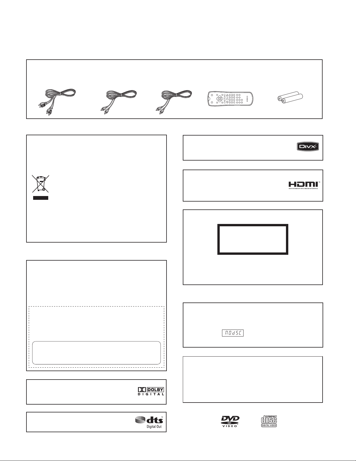
Accessories
ACCESSORIES / CAUTIONS
Audio cord (Red, White)
(x 1)
(E30-7381-08)
Video cord (Yellow)
(x 1)
(E30-7382-08)
Coaxial cable (Black)
Cautions
Information on Disposal of Old Electrical
and Electronic Equipment (applicable for EU
countries that have adopted separate waste
collection systems)
Products with the symbol (crossed-out wheeled
bin) cannot be disposed as household waste.
Old electrical and electronic equipment should
be recycled at a facility capable of handling
these items and their waste by products.
Contact your local authority for details in locating a
recycle facility nearest to you.
Proper recycling and waste disposal will help conserve
resources whilst preventing detrimental effects on our
health and the environment.
(x 1)
(E30-7383-08)
DivX, DivX Certified, and associated logos
are trademarks of DivX, Inc. and are used
under license.
HDMI, the HDMI logo and High-Defi nition
Multimedia Interface are trademarks or
registered trademarks of HDMI licensing
LLC.
Remote control unit
(RC-D0314 x 1)
(A70-1717-08)
Remote control batteries
(R03 x 2)
(-)
The marking of products using lasers
CLASS 1
LASER PRODUCT
For the U.S.A.
CAUTION:
Use of controls or adjustments or performance of
procedures other than those specifi ed herein may result in
hazardous radiation exposure. In compliance with Federal
Regulations, the following are reproductions of labels on,
or inside the product relating to laser product safety.
KENWOOD CORPORATION
2967-3, ISHIKAWA-CHO,
HACHIOJI-SHI,
TOKYO, JAPAN
KENWOOD CORP. CERTIFIES THIS EQUIPMENT
CONFORMS TO DHHS REGULATIONS NO. 21 CFR
1040.10, CHAPTER 1, SUBCHAPTER J.
Manufactured under license from Dolby
Laboratories. “Dolby” and the double-D
symbol are trademarks of Dolby Laboratories.
“DTS” and “DTS Digital Out” are registered
trademarks of DTS, Inc.
The marking this product has been classifi ed as Class 1.
It means that there is no danger of hazardous radiation
outside the product.
Location: Back panel
Caution for Transport or Movement
Before transporting or moving the system, prepare it as
described below.
Switch the system ON without placing a disc in it.
q
Ensure that
w
Wait a few seconds, and then switch the system OFF.
e
Operation to reset
The microprocessor may fall into malfunction (impossibility
to operate erroneous display, etc.) when the power cord is
unplugged while power is ON or due to an external factor.
In this case, switch off the power, wait for several seconds,
and then switch the power on again.
is displayed.
2

PARENTAL LOCK / DISASSEMBLY FOR REPAIR
hole A
(L3)
DVF-5400
FIG. 1-1
How to Reset Parental Lock
1. Connect the TV set to DVF-5400.
2. Push the power switch of DVF-5400 to be on.
3. Check the display of DVF-5400 shown “NO DISC”.
4. Push the “SETUP” key of remote control and TV has “set
up menu”.
5. Select the “16:9” on TV.
6. Push # key 1397139 and ENTER. Push # key again if
mistype.
7. Push the power switch of DVF-5400 to be off.
1. TRAY DISC (FIG. 1-1)
1) Insert and push a Driver in the emergency eject hole (A)
at the right side, or put the Driver on the Lever (B) of the
Gear Emergency and pull the Lever (B) in direction of
arrow so that the Tray Disc is ejected about 15~20mm.
2) Pull the Tray Disc until it is separated from the Base Main
completely.
2. FRAME ASSEMBLY UP/DOWN (FIG. 2-2)
Note
Put the Base Main face down (Bottom Side)
1) Release the screw (S4)
2) Unlock the Locking Tab (L3) in direction of arrow and
then lift up the Frame Assembly Up/Down to separate it
from the Base Main.
Note
• When reassembling move the Guide Up/Down in direction
of arrow (C) until it is positioned as Fig. (C).
• When reassembling insert (A) portion of the Frame
Assembly Up/Down in the (B) portion of the Guide Up/
Down as Fig. (B)
FIG. 2-2
3. BELT LOADING (FIG. 2-2)
Note
Put the Base Main on original position (Top Side)
4. GEAR PULLEY (FIG. 2-2)
1) Unlock the Locking Tab (L4) in direction of arrow (B) and
then separate the Gear Pulley from the Base Main
5. GEAR LOADING (FIG. 2-2)
6. GUIDE UP/DOWN (FIG. 2-2)
1) Move the Guide Up/Down in direction of arrow (A) as Fig.
(A)
2) Push the Locking Tab (L5) down and then lift up the Guide
Up/Down to separate it from the Base Main.
Note
When reassembling place the Guide Up/Down as Fig. (C)
and move it in direction arrow (B) until it is locked by the
Locking Tab (L5). And confi rm the Guide Up/Down as Fig. (A)
7. PWB ASSEMBLY LOADING (FIG. 2-2)
Note
Put the Base Main face down (Bottom Side)
1) Release 1 Screws (S5)
2) Unlock the Loading Motor (C2) from the Hook (H1) on
the Base Main.
3) Unlock 2 Locking Tabs (L6) and separate the PWB
Assembly Loading from the Base Main.
3
4
DVF-5400
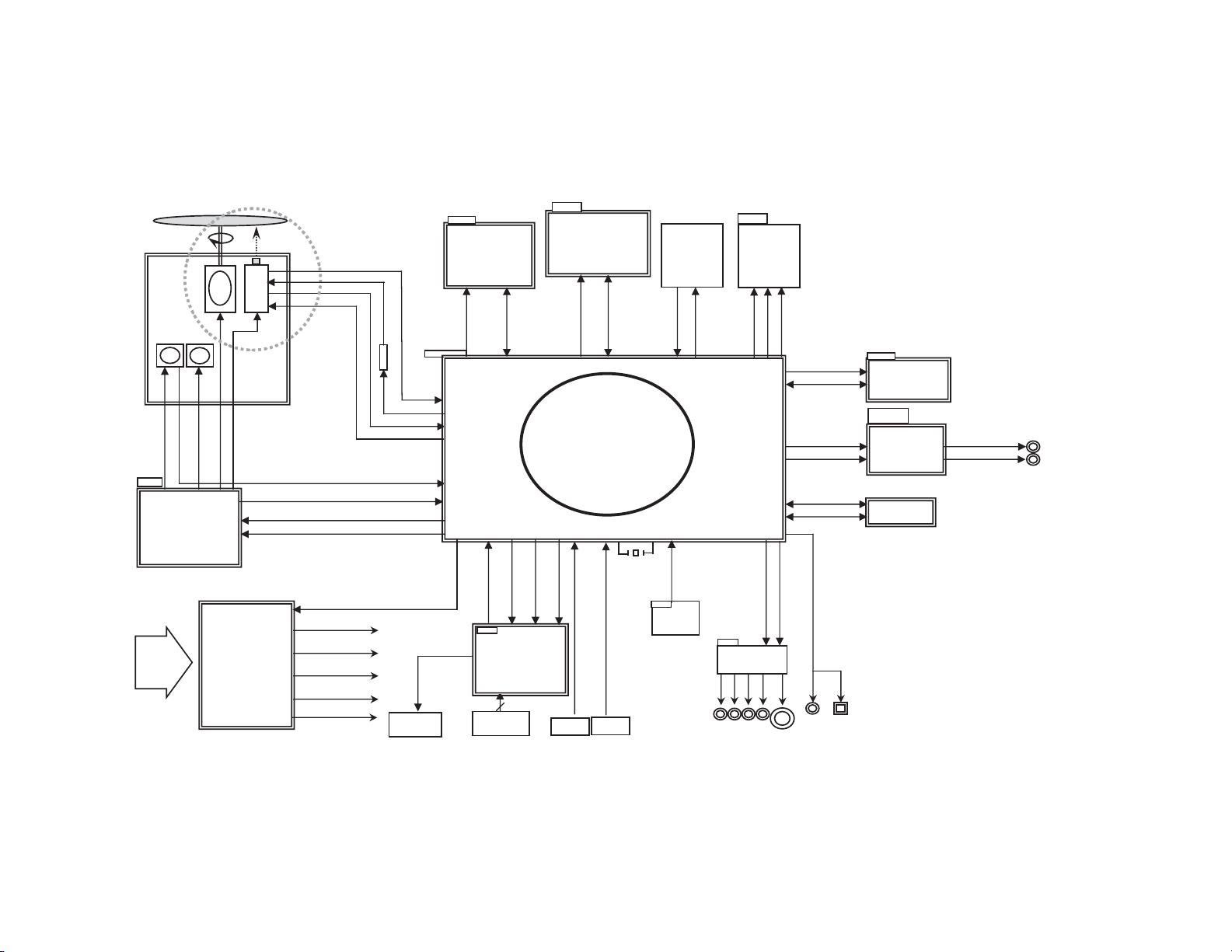
1. OVERALL BLOCK DIAGRAM
SPINDLE
MOTOR
LOADING
MOTOR
DECK MECHANISM
M
LOAD[+,-]
A
5.6V
IC201
AM58
Motor Driv
AC 90V~240V
50HZ/60Hz
DISC
SLED
(FEEDING)
MOTOR
M
69S
PICK
M
SLED[+,-]
FACT[+,-]
TACT[+,-]
SP [+,-]
OPEN,
e
POWER
BOARD
A,B,C,D,RF
DVD :
CD : A,B,C,D,E,F,RF
UP
CD_DVD, VR_CD,VR_DV
CD_LD,DVD_LD,V
PICKSEL
D
C
Pick-up
INSW,OUTS
W
SPDL_SENS+ ,1.8VA
CLOSE,SLED_S,SPINDLE_S,FOCU S_S,TRACK_S
DRVSB
POWCTL_H
5V
12V
3.3V
3.3VA
5.6VA
CD_DVD
DIG901
LED Cloc
V33A
MX29LV160TTC
FLASH RO
V18A/V33A
k
IC604
16/32BIT
D-
MEMAD[0:19]
FLASHCS-
MEMWR-
MEMR
Dout
Din
5V
ETK6203
LED DRIVER
KEY In
V33A
IC603
ESMT_M12L64164A
4M/16BIT
SDRAM
M
RA
MAD[00:11]
RAMCKE
PCLK
RAMBA
RAMCS1
RAMDQM
RAMWE
MEMDA[0:15]
RAMCAS
RAMRA
S
IC601
ZORAN ZR36888
CLK STB
Power
Key
Power
On
RC901
R/C
IC901
3
put
HDMI
5V
CN601
CN602
Download
I/F
15]
RAMDAT[00:
DUPTR0
DUPTD0
JK705
HDMI
Jack
I2CCLK/MC
I2CDAT/MD
V33DA
IC605
S524C80D80
BLOCK DIAGRAM
EEPROM
12V
AL
AR
RF+DSP
USB_
USB_
DN
DP
MPEG IC
R
TV_DAC[0:3]
Y
C
COAXIAL
ASPDIF
Optical
Option
27MHz
RESET
3.3V
A
IC606
KIA7027
RESET IC
5V
MM1692XVBE
VIDEO BUFFE
CVBS
IR
IC701
R/Pr G/
YC_MIX
Y
B/Pb
IC703
udio Op-amp
A
AZ4580M
CN610
To USB2.0
Boar
d
AL
AR

2. POWER (SWPS) BLOCK DIAGRAM
8V
3.3V
FILTER
SWIT
CHING IC
TRANS
FEED B.
3.3VA
RECTIFIE
R(5.6V)
RECTIFIE
R(9.5V)
LPF
RECTIFIE
R(14V)
LPF
12V
PWR CT
L
5V
5.6V(M)
/ 5.6VA
RECTIFIE
R(3.4V)
LPF
AC100~240V
RECTIFIER
REG.
T/ W
P
DVF-5400
BLOCK DIAGRAM
3. MPEG & MEMORY BLOCK DIAGRAM (ZR36888)
JK705
HDMI
JA
STB
CLK,
CK
TXC+TXC-
TX0+,TX0-,TX1+,TX1-
TX2+,TX2-,
IC601 (MPEG + DSP + RF)
ZR36888
X60
1
z
27MH
To USB2.0
Board
IC606
RESET
CN610
RESET
IC
USB_DN
USB_DP
DIN ,DOUT
IC901
LEDDRIVE IC
RAMCAS
[00:15]
RAMRAS
RAMDAT
IC603
SDRAM
64M
RAMAD[00:11] ,RAMCKE
PCLK ,RAMBA,RAMCS1
RAMDQM ,RAMWE
A[0:15]
MEMAD[0:19]
FLASHCS-
MEMWR-
MEMRD
MEMD
IC604
FLASH MEMORY
(16 M )
I2CCLK/MC
T/MD
I2CDA
C_Y, S_Y
SY_Pr_OUT,Y_OUT,SC_Pb_out
RGB_SEL,16 _9_H
AMCLK,ALRCK,ABCK
D_MUTE
AOUT0.ML
IC605
EEPRO
I2CCLK/MC, I2CDAT/MD
ASPDIF
M
VIDEO
Interface
AUDIO
Interface
5

DVF-5400
4. SERVO BLOCK DIAGRAM (ZR36888)
PICK
UP
M/D
FACT+, FACTTACT+, TACT-
-
SP+, SP
ED-
SLED+, SL
LOAD+, LOAD-
BLOCK DIAGRAM
ALPC
CD_LD,DVD_LD
CD_DVD
VR_DVD,VR_CD
V
20, PICKSEL
DVD: A,B,C,D, RFO
CD:A,B,C,D,E,F,RF
TRIN,TROUT
O
IC201
AM5869S
Motor Driver
SPDL_SENS+ ,1.8
OPEN,CLOSE,SLED_S,SPINDLE_S,
FOCUS_S,TRACK_S, DRVSB
DVDPLAYER
ONE CHI P
VA
X601
27MHz
X-TA
IC601
ZR36888
RAMADD[0:11]
RAMDQM,
PCLK,RAMBA
RAMCS1,
RAMCAS,RAMRAS
RAMDAT[0:15]
IC603
4M x 16bit
SDRAM
L
MEMDA[0:15]
RAMWE
RAMCKE
MEMAD[0:19]
MEMWR,MEMRD
MEMCS
I2CCLK
I2CDAT
DUPTD0
DUPTR0
FLASH
ROM
EEP
ROM
RS232C
5. VIDEO & AUDIO BLOCK DIAGRAM
(SY_Pr_OUT,Y_OUT,SC_Pb_OUT)
MPEG
MPEG
(C_Y/S_Y)
AL
AR
IC701
VIDEO 6dB
Amp
CVBS
COMPONENT (R.G.B) / (Y.Pb.Pr )
SUPER VIDEO (Y/C)
IC672 (OP Amp)
LPF&Buffer
A/V
JACK
AUDIO"L"
AUDIO"R"
6

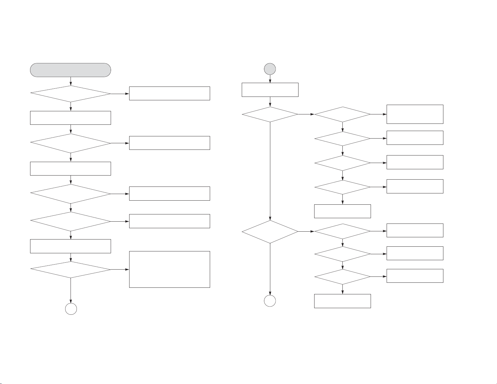
1. POWER CHECK FLOW 2. SYSTEM OPERATION FLOW
A. B.
No 5V No 3.3VA
Is 3.3VA
section working?
YES
Is 5.6V present at
collector of Q126?
YES
NO
No 3.3VA
NO
NO
Replace Q126. Check FR101 Replace Q121.
Is there a DC voltage at
NO
cathode of D105 or D107?
YES
Replace IC101.
Is 3.3VA
section working?
YES
Is 3.3V
present at emitter
of Q121?
YES
YES
Check D105/D106/D107/
D108 and replace.
Power on
1. 186 CPU initializes SERVO, DSP &
RISC registers
2. Write RISC code to SDRAM
3. Reset RISC
Show LOGO
YES
1. Judge whether have disc and disc type
2. Jump to related disc reading procedure
1. Execute pressed key & IR key
2. System operation routine loop
Tray closed?
NO
Tray close to closed position
SLED at inner side?
NO
SLED moves to inner position
Recieve
OPEN/CLOSE key?
NO
TROUBLESHOOTING
YES
YES
DVF-5400
Note: This shooting is the original circuitry so there are some different points from DVF-5400.
7
1. Stop playback & open tray
2. Display tray open message & LOGO
NO
Receive CLOSE key?
YES
8
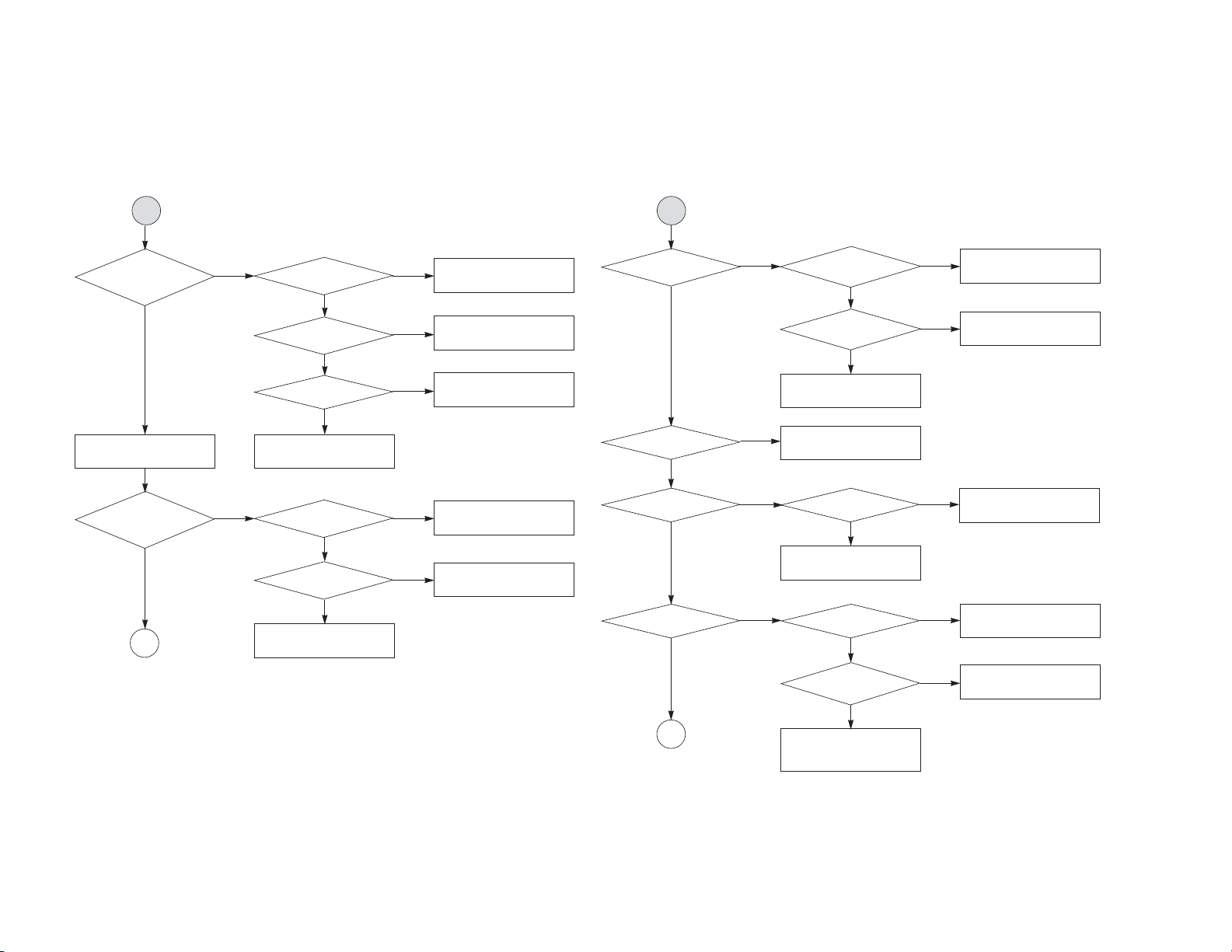
3. SYSTEM TEST FLOW
DVF-5400
TEST
Check the AC
Voltage power PCBA (110V or
Switch on the power PCBA
Make sure the main PCBA don't
short on VCC and switch it on.
Connect to PC RS232 cable and
update the FLASH memory code.
220V)
YES
Is the DC
voltage outputs OK?
(5V, 3.3V, 12V, 5.6V
MOTOR)
YES
YES
Is 3.3V
outputs normal on main
PCBA?
YES
Is 1.8V voltage
normal for ZORAN IC
YES
Update FLASH
successfully?
YES
A
NO
Replace power PCBA or AC transformer.
NO
NO
NO
NO
Repair or replace power PCBA
Check the regulators or related diodes.
1. Check Q203.
2. Check D201.
3. Check IC102.
1. Check 27MHz system clock.
2. Check system reset circuit.
3. Check FLASH R/W enable signal PRD,
RWR.
4. Check RS232 SIGNALS.
5. Check FLASH memory related circuit.
A
RESET or power on.
Show LOGO?
YES
Does tray
move inside when it is not
at closed position?
YES
B
NO NO
NO
Flash
memory operates
properly?
YES
SDRAM
works properly?
YES
ZR36888
VIDEO outputs
properly?
YES
Have TV
signal output?
YES
Check AV cable
connection to TV set.
Normal
OUTSW & INSW
signals?
YES
Normal
OPEN & CLOSE
signal?
YES
Normal
LOAD+ & LOAD
signal?
YES
Check the cable
connection between main
PCBA and loader.
NO
NO
NO
NO
NO
NO
Check connection lines
between FLASH & ZR36888
and the FLASH access time
whether is suitable or not.
Check connection lines
between SDRAM & ZR36888
and the SDRAM is damaged.
Check the related circuit of
ZR36888
Check the filtering and amp
circuit of TV signal.
Check the load OPEN &
CLOSE switch
Check the tray control IO
pins on ZR36888 & AM5869S
Check the tray control
amplifying circuit on motor
driver.
TROUBLESHOOTING
B
C
Does the
SLED move
to inner side when it is at
outer position?
YES
Do not put in disc and
tray close.
Optical Lens has
movements for searching
Focus?
YES
C
Motor
driver MUTE pin
is high?
YES
Is SLED_S
DC Level higher than
1.65V?
YES
SLED+
and SLED- output
properly?
YES
Check the cable connection
with MECHA.
Proper
FOCUS_S outputs to
motor driver?
YES
Proper
FACT+ & FAC
toutputs?
YES
Check cable connect on
with pick-up head.
NONO
Check the connection line of
MUTE signal.
Check the related circuit of
NO
NO
NONO
NO
Check the amp circuit on
motor driver.
Check FOCUS_S connection
on ZR36888 and motor driver.
Check the amp circuit on
motor driver.
FMSO.
Laser
turns on when reading
disc?
YES
Put disc in?
YES
Disc ID is correct?
YES
Does
spindle rotate?
YES
D
NO NO
NO
NO
NO NO
LD_DVD or
LD_CD output
properly?
YES
Collector
voltage of power transistor
is OK?
YES
Check cable connection
between transistor output
and pick-up head.
Laser off
Proper RF signal
on ZR36888?
YES
Check LD_DVD &
LD_CD signal
Proper
SPINDLE_S signal on
ZR36888
YES
SP+ & SP- output
properly?
YES
Check the cable connection
between spindle and main
PCBA.
NO
NO
NO
Check the laser power circuit
on ZR36888 and connecting
to power transistor.
Check the related circuit on
laser power transistor
Check the related circuit
on ZR36888 RFL signal.
Check SPINDLE_S related
circuit on ZR36888.
Check the spindle control
amp circuit of motor driver.
TROUBLESHOOTING
DVF-5400
9

10
DVF-5400
D
Focus on OK?
YES
Track on OK?
YES
NO NO
NO NO
Proper
signals on A, B, C, D of
ZR36888
YES
Check FE signal
on ZR36888
YES
Check FOCUS_S signal
on ZR36888
Normal
TE signal on
ZR36888?
YES
Properly
TRACK_S signal on
ZR36888?
YES
TACT+ & TACToutput properly?
YES
Check cable connection on
pick-up head.
NO
NO
NO
Check connections between
ZR36888 and pick-up head.
Check the FOCUS_S
connection on ZR36888
and motor driver.
Check the related
circuit on ZR36888
Check the TRACK_S
connection on ZR36888
and motor driver.
Check the tracking control
amp circuit on motor
driver.
E
Normal
audio output when disc
playback?
YES
Normal
IR.VFD & Front panel
key functions?
YES
TEST END
NO
NO NO
Audio DAC
received correct data
stream?
YES
Normal
audio DAC out?
YES
Check audio filter,
amplify, mute circuit.
Commu-
nications between
IR.VFD Front panel key
& ZR36888 is
normally?
YES
Check the cable connection
on front panel.
NO
NO
Check connection between
ZR36888 & audio DAC.
Check the related
circuit of Audio DAC.
Check communication lines
on ZR36888
TROUBLESHOOTING
Disc is play?
YES
E
NO
Check RF signal waveform.
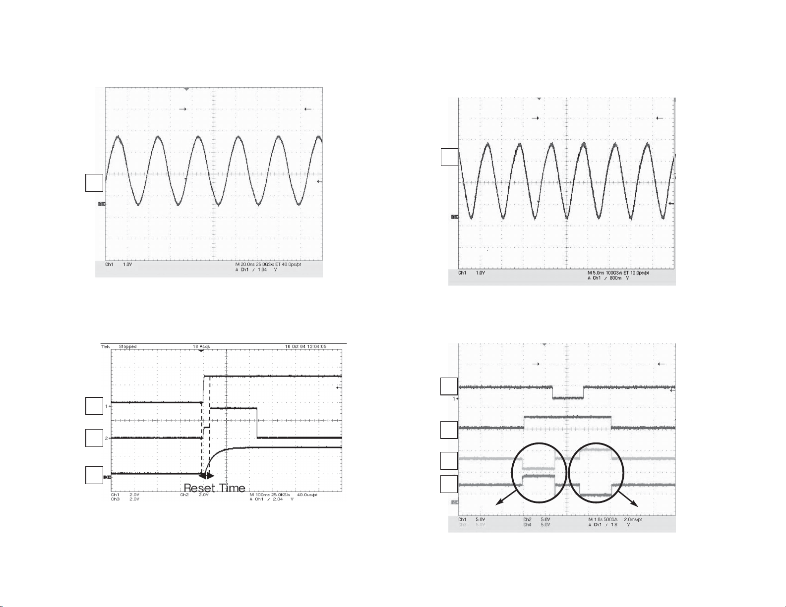
1. SYSTEM 27MHz CLOCK, RESET, FLASH R/W SIGNAL
1) ZR36888 main clock is at 27MHz (X601)
1
3.1V, 27MHz
FIG 1-1
2. SDRAM CLOCK
1) SDRAM clock is at 143MHz
CLK=143MHz, Vp-p=3.3V
5
IC603 38PIN
WAVEFORMS
FIG 2-1
2) ZR36888 reset is low active
2
PWR_CTL
3
4
FIG 1-2
Note: Refer to Schematic Diagram on waveform’s check point.
11
3.3VA
RESET
3. TRAY OPEN/CLOSE SIGNAL
1) Tray open/close waveform
6
7
8
9
FIG 3-1
OPEN
CLOSE
LM-
LM+
DVF-5400
ESOLCNEPO
 Loading...