

COMPACT DISC PLAYER
DP-SG7/SG7G
SERVICE MANUAL
© 1999-7/B51-5542-00 (K/K) 2299
70%
60
repeat 7
¢4
1
timespace
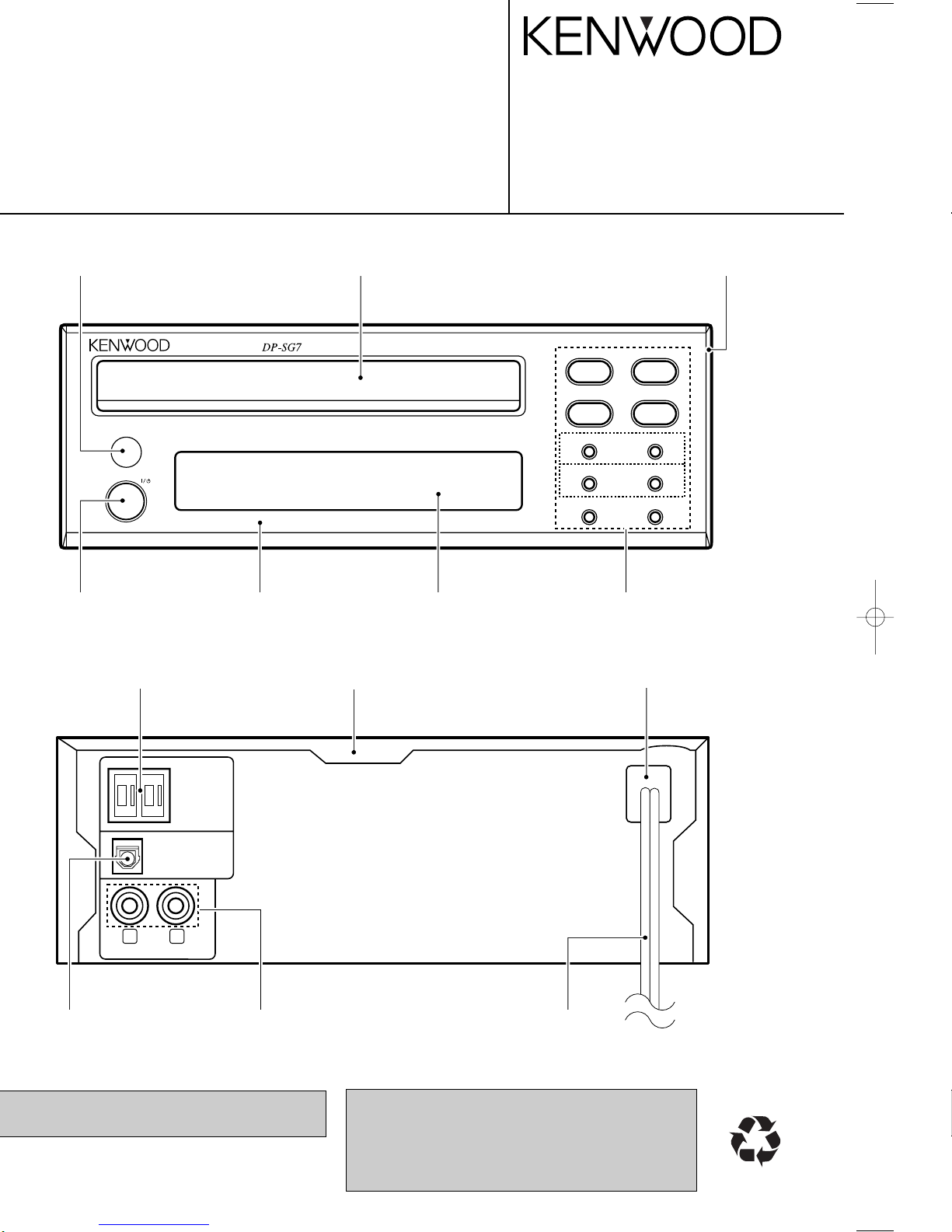
compact disc player
D.R.I.V.E.with 24bit D/A converter
on/standby
24bit Fine D.R.I.V.E.
'
603616617
651 606 604 650
OPTICAL
SYSTEM
CONTROL
DIGITAL OUT
PLAY OUT
R
L
AC power cord *
(E30-)
Oscillating module
(W02-1114-05)
Phono jack
(E63-0122-05)
Metallic cabinet
(A01-3313-01)
Power cord bushing
(J42-0083-05)
Rectangular receptacle
(E08-0312-05)
Illustration is DP-SG7.
* Refer to parts list on page 15.
KENWOOD-Crop. certifies this equipment conforms to
DHHS Regulations No. 21 DFR 1040. 10, Chapter 1, Subchapter J.
DANGER : Laser radiation when open and interlock
defeated.
AVOID DIRECT EXPOSURE TO BEAM
Indicator
(B12-0318-04)
Panel
(A60-1671-03)
Panel
(A29-1058-03)
Knob (POWER)
(K29-6741-04)
Front glass
(B10-2372-03)
Knob
(K29-7571-03)
SUB panel
(A22-1778-31)
CONTENTS / CAUTIONS
SCHEMATIC DIAGRAM............................................ 7
EXPLODED VIEW ....................................................13
PARTS LIST..............................................................15
SPECIFICATIONS ......................................Back cover
DP-SG7
Pull the power plug from the receptacle, and then
plug it in again.
DP-SG7/SG7G
3
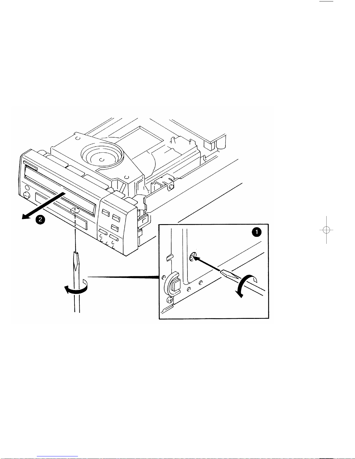
DISASSEMBLY FOR REPAIR
clockwisely about 100° (1).
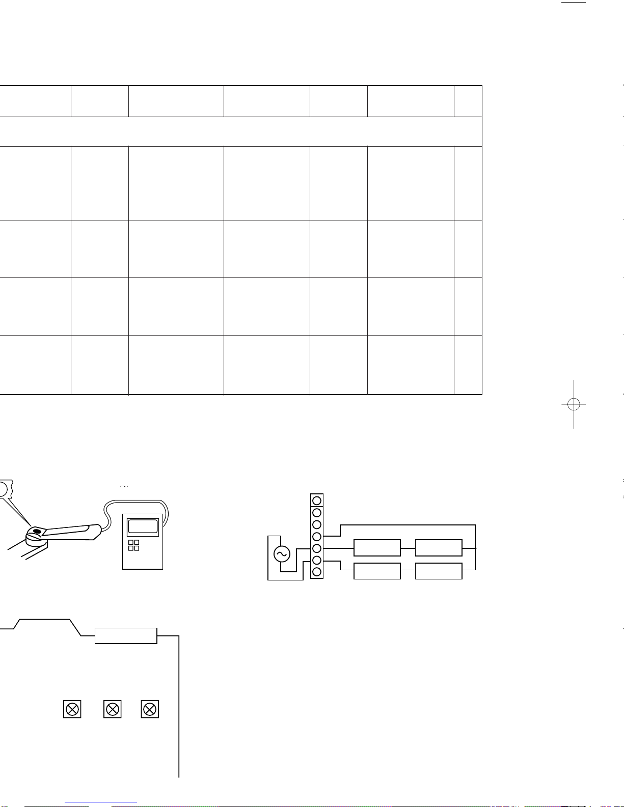
ADJUSTMENT
FIG.
VC
CN3
L.P.F.
+
+
L.P.F.
VTVM
VTVM
1
2
3
4
5
6
7
1.2 kHz
50 mVrms
RF
FE1
FE2
VC
TE2
TE1
S.S
+
_
(a)
INPUT
SETTINGS
OUTPUT
SETTINGS
ALIGNMENT
POINTS
ALIGN
FOR
PLAYER
SETTINGS
−
Apply the sensor section
of optical power meter
on the pickup lens.
−
On the power from
0.08 to 0.15 mW,
when the diffraction
grating is correctly
aligned with the RF
level of 0.6 Vp-p or
more.
Press the
PLAY/PAUSE key,
then confirm that the
LED is "03".
Pickup
BIAS
Test disc
Type 4
Connect an oscilloscope
as follows.
CH1 : RF (CN3 pin 1)
CH2 : TE (CN3 pin 6)
FE BIAS
VR2
Optimum eye pattern
Press the
PLAY
/PAUSE
key,
then confirm that the
LED is "05".
0.08 0.15 mW
Optical power meter
BALANCE
Test disc
Type 4
Connect an oscilloscope
as follows.
CH1 : RF (CN3 pin 1)
CH2 : TE (CN3 pin 6)
TE BALANCE
VR1
Symmetry between
upper and lower pat-
terns
Press the
PLAY/PAUSE key,
then confirm that the
LED
is "03".
(e)4 TRACKING GAIN
Test disc
Type 4
Apply signal of
1.2 kHz,
50mVrms to
CN3 pin 5-6.
Connect a LPF to CN3
pin 5-6 to which you
connect an oscilloscope
or AC voltmeters.
TRACKING
GAIN
VR3
Two VTVMs should
read the same value.
Press the
PLAY/PAUSE key,
then confirm that the
LED
is "05".
(e) Tracking gain(a) Laser power
T-GAIN
VR3 VR1 VR2
CN1
TE-B FE-B
ACEGIBDFHJ
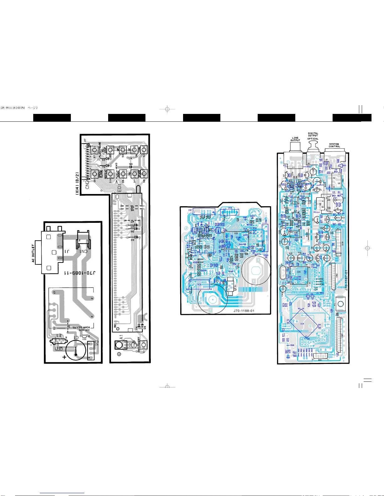
Refer to the schematic diagram for the value of resistors and capacitors.
PC BOARD(Component side view
)
5 6
CD PLAYER UNIT
(X32-3600-00)
ELECTRIC UNIT
(X25-6100-01)
DISPLAY UNIT
(X14-4760-21)
 Loading...