

Page 1
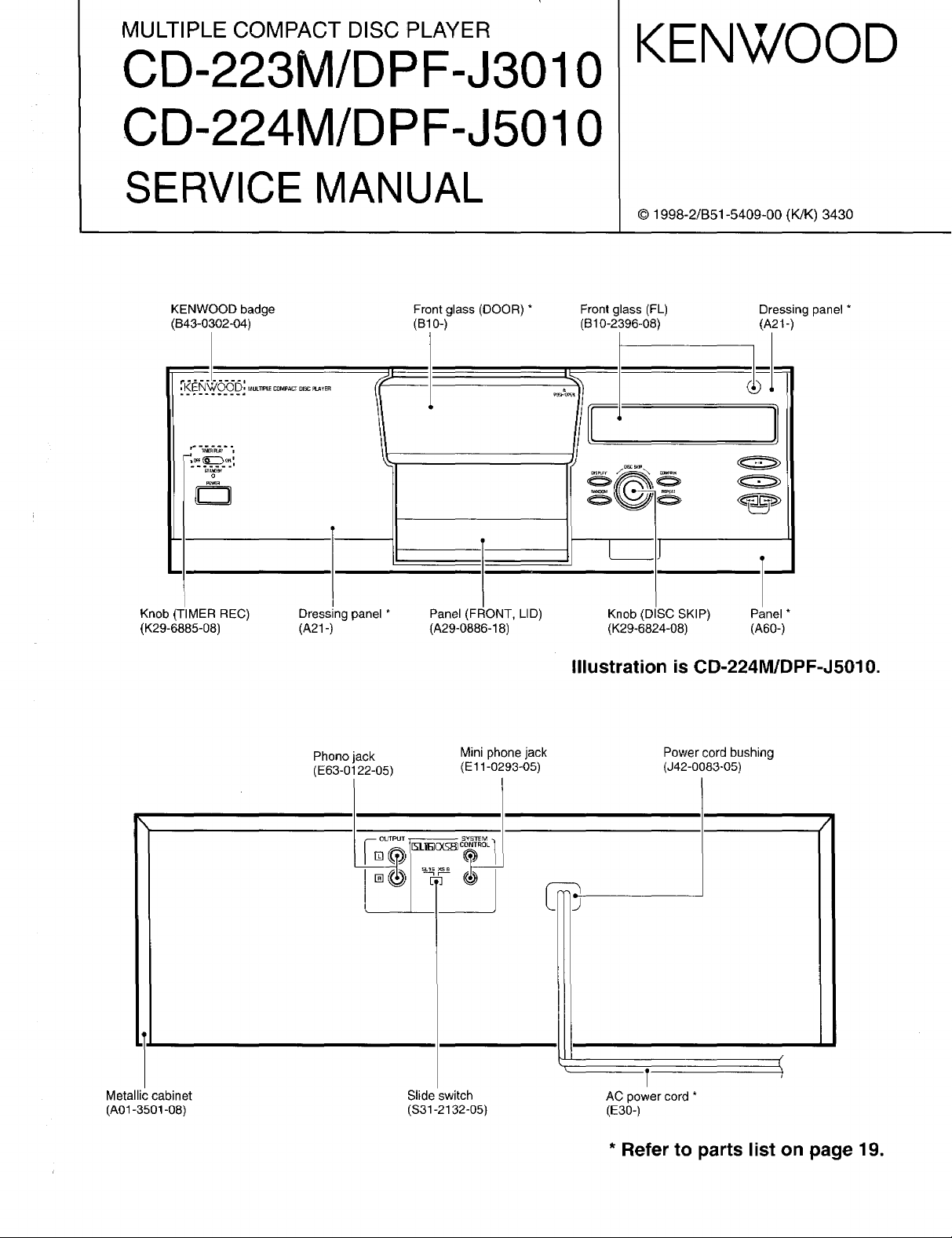
MULTIPLE COMPACT DISC PLAYER
CD-223M/DPF-J3010
CD-224M/DPF-J5010
SERVICE MANUAL
KENWOOD
© 1998-2/B51-5409-00 (K/K) 3430
KENWOOD badge Front glass (DOOR) *
(843-0302-04) (B10-)
= .... " .... I
KENWOOD MtlL'i_'E0OMP,_CTDISC_¥E.
C3
Knob TIMER REC) Dressing panel *
(K29-6885-08) (A21 -)
Phono jack
(E63-0122-05)
Panel (FRONT, LID)
(A29-0886-18)
Mini phone jack
(El 1-0293-05)
Front glass (FL)
(B10-2396-08)
Knob (DISC SKIP) Panel *
(K29-6824-08) (A60-)
Dressing panel *
(A21-)
Illustration is CD-224M/DPF-J5010.
Power cord bushing
(J42-0083-05)
Metallic cabinet
(A01-3501-08)
SYs_M
3L5_CONTROL1
o0_I--
,5-
Slide switch
($31-2132-05)
T
AC power cord *
(E30-)
* Refer to parts list on page 19.
Page 2
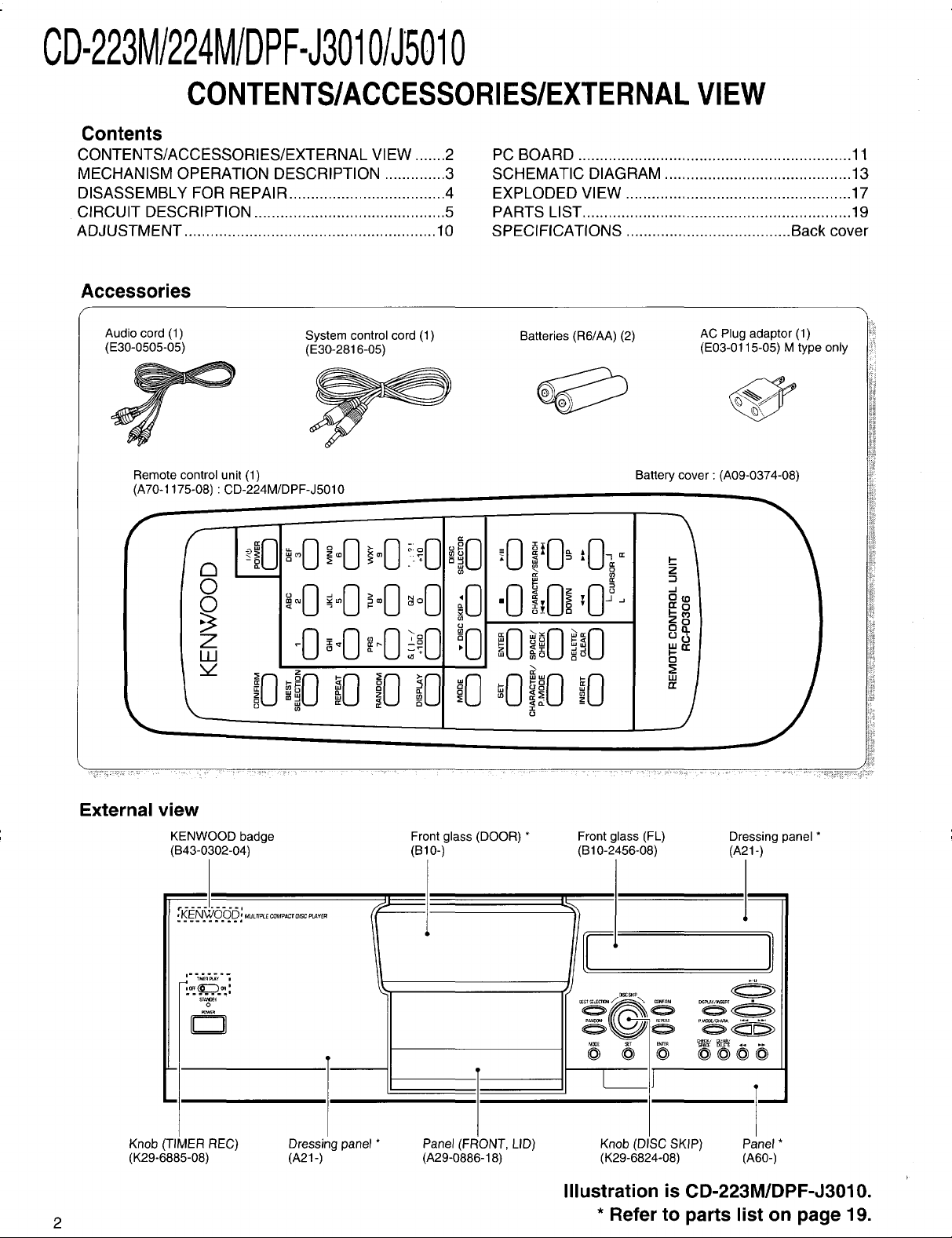
CD-223M/224M/DPF-J3010/J5010
CONTENTS/ACCESSORIES/EXTERNALVIEW
Contents
CONTENTS/ACCESSORIES/EXTERNAL VIEW .......2
MECHANISM OPERATION DESCRIPTION .............. 3
DISASSEMBLY FOR REPAIR .................................... 4
CIRCUIT DESCRIPTION ............................................ 5
ADJUSTMENT .......................................................... 10
Accessories
PC BOARD ............................................................... 11
SCHEMATIC DIAGRAM ........................................... 13
EXPLODED VIEW .................................................... 17
PARTS LIST .............................................................. 19
SPECIFICATIONS ...................................... Back cover
Audio cord (1)
(E30-0505-05)
Remote control unit (1)
(A70-1175-08) ' CD-224M/DPF-J5010
0
Z
W
v
\
System control cord (1)
(E30-2816-05)
Batteries (R6/AA) (2)
_o
_0
o
,ll i
•0!:Oi,O_.
__u
o
_0_0;:0"°°:0
AC Plug adaptor (1)
(E03-0115-05) M type only
Ba_e_ cover:(A09-0374-08)
iii;
8_
J
External view
2
KENWOOD badge Front glass (DOOR) *
(B43-0302-04) (B10-)
KENWOOD MUL._ECOMP_Cr._C_Y_.
:2222"22222_
.- -_-_-
'_.._.._:
Knob (TIMER REC) Dressing panel * Panel (FRONT, LID)
(K29-6885-08) (A21-) (A29-0886-18)
Front glass (FL)
(B10-2456-08)
lsc sKl_
Dressing panel *
(A21-)
T
Knob (DISC SKIP) Panel *
(K29-6824-08) (A60-)
Illustration is CD-223M/DPF-J3010.
* Refer to parts list on page 19.
Page 3
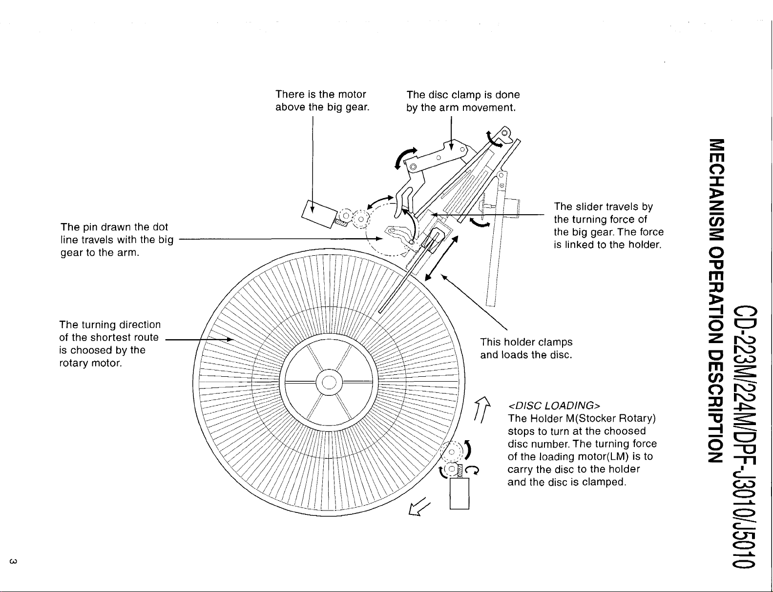
There is the motor
above the big gear.
The disc clamp is done
by the arm movement.
1"!3
The pin drawn the dot
line travels with the big
gear to the arm.
The turning direction
of the shortest route
is choosed by the
rotary motor.
The slider travels by
the turning force of
the big gear. The force
is linked to the holder.
This holder clamps
and loads the disc.
<DISC LOADING>
The Holder M(Stocker Rotary)
stops to turn at the choosed
disc number. The turning force
of the loading motor(LM) is to
carry the disc to the holder
and the disc is clamped.
Z
O
I'i"1
;ZI
Z "-n
O
O
O
O
Page 4
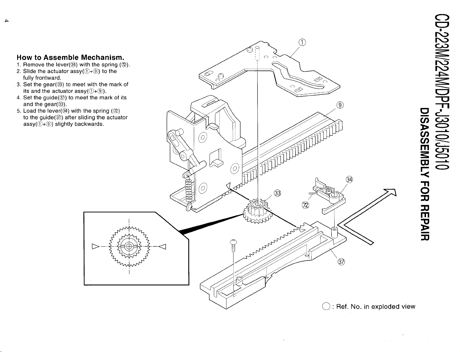
How to Assemble Mechanism.
1. Remove the lever(Q) with the spring (@).
2. Slide the actuator assy(_)+®) to the
fully frontward.
3. Set the gear(Q) to meet with the mark of
its and the actuator assy(_+®).
4 Set the guide(Q_) to meet the mark of its
and the gear(@).
5. Load the lever(_) with the spring (@)
to the guide(@) after sliding the actuator
assy(_+®) slightly backwards.
0
EC_
--r'l
t_
Ill o'-i
_o
0
@
®
/
@
(_" Ref. No. in exploded view
"11
0
:zI
m
Page 5
CD-223M/224M/DPF-J3010/J5010
CIRCUITDESCRIPTION
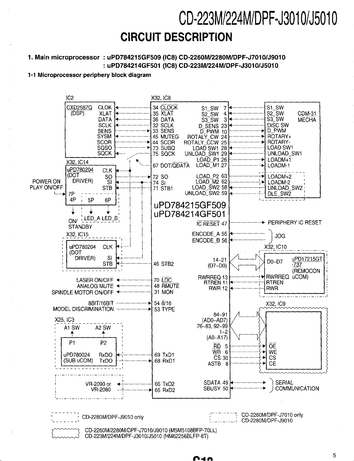
1. Main microprocessor : uPD784215GF509 (IC8) CD-2260MI2280M/DPF-J7010/J9010
: uPD784214GF501 (IC8) CD-223M/224M/DPF-J3010/35010
1-1 Microprocessor periphery block diagram
1C2 X32, lC8
DATA
SCLK
SENS
SO
STB
4
4
4
u --i --
34 CLOCK SI_SW 7
35 XLAT S2_SW 4
36 DATA S3_SW 3
32 SCLK D SENS 23
33 SENS E)-PWM 10
45 MUTEG ROTAL_.( CW 24
,44 SCOR ROTALY_C_,CW 25
,73 SUBQ LOAD SWl 28
75 SQCK UNLOAD_SWl 29
LOAD_P1 26
67 DOT/QDATA LOAD_M1 27
72 SO LOAD_P2 63
74 SI LOAD M2 62
71 STB1 LOAD_SW2 58
UNLOAD_SW2 59
uPD784215GF509
uPD784214GF501
IC RESET .47
ENCODE A 55
ENCODE_B56
14~21
46 STB2 (D7-D0)
r--
_1- t--
q
I--
CXD2587Q CLOK
(DSP) XLAT
SYSM
SCOR
SQSO
SQCK
X32_IC14
tuPD780204 CLK
I(DOT
POWER ON I DRIVER) -SI
PLAY ON/OFF I STB
ON/ _LED_A LED_B
STANDBY
X32,IC15
uPD780204 CLK
(DOT
DRIVER) SI
SI_SW
S2_SW CDM-31
S3SW MECHA
DISC SW
D_PWM
ROTARY+
ROTARY-
LOAD SWl
UNLOAD SWl
LOADM+I
LOADM-1
-I_OADM+2 ;
LOADM-2
UNLOAD SW2 1
DLE_SW2 ',
J
_" PERIPHERY IC RESET
LASER ON!OFF 4
ANALOG MUTE 4
SPINDLE MOTOR ON/OFF 4
8BITi16BIT
MODELDISCRIMINATION
X25, IC3
A1 SW A2 SW ',
f t ;
P1 P2 ,
I t'
uPD780024 RxDO -'
L(SUB uCOM) TxDO
......................... i
VR-2090 or
VR-2080
........................ -]
, CD-2280MiDPF-J9010 only
I
CD-2260Mi2280M/DPF-J7010iJ9010(M5M5108BFP-70LL)
CD-223M/224MiDPF-J3010/J5010(HM62256BLFP-ST)
70 LDC RTREN 11
48 RMUTE RWR 12
31 MON
54 8/16
RWRREQ 13
X32, IC9
53 TYPE
84~91
(AD0~AD7)
76~83, 92~99
1~2
(A0~A17)
R-D 5 I
69 TxD1
68 RxD1
I
I
66 TxD2
65 RxD2
WR 6 I
CS 30
ASTB 8
SDATA 49
SBUSY 50
\
/
-_ OE
÷ WE
-_ CS
÷ CE
_" _ SERIAL
+" COMMUNICATION
'- ........ q CD-2260MiDPF-J7010only
1.......... L CD-2280MiDPF-J9010
ir.lh4 _ 5
Page 6
CD-223M/224M/DPF-J3010/J5010
CIRCUITDESCRIPTION
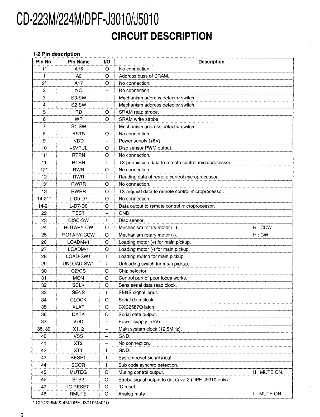
1-2
Pin description
Pin No.
1"
1
2*
2
3
4
5
6
7
8
9 j VDD
10 t +5VPUL
11* T RTRN
11 RTRN
12* f RWR
12 RWR
13" RWRR
13 RWRR
14-21" L-D0-D7
14-21 I L-D7-DO
22 _ TEST
23 DISC-SW
24 _ ROTARY-CW
25 I ROTARY-CCW
26 LOADM+I
27 LOADM-1
28 LOAD-SW1
29 ! UNLOAD-SW1
30 CE/CS O
31 MON O
32 ] SCLK O
33 I SENS I
34 _ CLOCK O
35 XLAT O
36 I DATA O
37 i VDD -
38, 39 X1, 2 -
40 . VSS -
41 / XT2 -
42 t XT1 I
43 RESET I
44 SCOR I
45 MUTEG O
46 ) STB2 O
47 IC RESET O
48 I RMUTE O
CD-223M/224M/DPF-J3010/J5010
Pin Name I/0 I Description
A16 O L No connection.
A2 O I Address buss of SRAM.
A17 O I No connection.
NC - No connection.
S3-SW I I I Mechanism address detector switch.
, S2-SW I Mechanism address detector switch.
RD O I SRAM read strobe.
I WR O SRAM write strobe
S1-SW I } Mechanism address detector switch.
ASTB O No connection.
I
/
/
i
[
Power supply (+5V).
O
Disc sensor PWM output.
O
No connection.
I
TX permission data to remote control microprocessor.
O
No connection.
Reading data of remote control microprocessor.
O
No connection.
L
_ 0
TX request data to remote control microprocessor.
No connection.
0 I
0
Data output to remote control microprocessor.
GND.
-1
I
Disc sensor.
Mechanism rotary motor (+).
o
Mechanism rotary motor (-).
o
Loading motor (+) for main pickup.
0
Loading motor (-) for main pickup.
I
Loading switch for main pickup.
I
Unloading switch for main pickup.
Chip selector
Control port of poor focus works.
Sens serial data read clock.
SENS signal input.
Serial data clock.
CXD2587Q latch.
I Serial data output.
Power supply (+5V).
Main system clock (12.5MHz).
GND.
No connection.
GND.
System reset signal input.
Sub code synchro detection.
Muting control output.
Strobe signal output to dot driver2 (DPF-J9010 only).
IC reset.
Analog mute.
H "CCW
H'CW
H " MUTE ON.
L : MUTE ON.
Page 7

CD-223M/224M/DPF-J3010/J5010
CIRCUITDESCRIPTION
Pin No.
49
5O
51
52
53
54
55
56
57
58
59
60
61
62 .
63
64
65
66
67
/k
68
69
70
71
72
73
74
75
76-83*
76-83
84-91
92-99*
92-99
100
CD-223M/224MiDPF-J3010/J5010
_. I/O port • O {when no used this port)
Pin Name
SDATA
SBUSY
AVDD
AVREF
AiD0
8/16
JOG2
JOG1
DOOR-SW
LOAD-SW2
UNLOAD-SW2
! DISC-SW2
VSS
LOADM-2
LOADM+2
AVREF1
RXD2
TXD2
SQCK/SCK-SW
RXD1
TXD1
LDC
STB1
SO
SQS1
$1
SCKiSQCK
A14-7
A16,14,12,7-3
D0-7
A1-6,15
A0,1,8-11,13,15
VSS
I/O
I/O
i Serial data signal I/O.
_l/O
i
I-
1-
I I
I I
' I
E O
i O
I I
L o
i
i o
! o
Serial busy signal IiO.
I Power supply(+5V).
AiD reference power supply.
I
Model selector.
I
8/16 bit selector. H:16bit.
I
Encoder signal A input.
Encoder signal B input.
! Door open/close detector switch.
Load switch2 for sub pickup(DPF-J9010 only).
I
Unload switch2 for sub pickup(DPF-J9010 only).
I
Disc2 sensor(DPF-J7010iJ9010 only).
GND.
O
Load motor(-) for sub pickup(DPF-J9010 only).
O
Load motor(+) for sub pickup(DPF-J9010 only).
DiA reference power supply.
I
UART communication input(DPF-J7010/J9010 only)
UART communication output(DPF-J7010iJ9010 onry)
o
"SQCK, SCK(DOTiDSP clock) serecter. L:DSP."
I
] UART communication input(sub u-com)(DPF-J9010 only).
O
! UAR'I" communication output(sub u-com)(DPF-Jg010 only).
Laser on/off.
O
Strobe signal output to dot driver.
I
I Data input from dot driver.
I Sub code read data input.
O
Data output to dot driver.
O
Dot driver/sub code read clock.
, Address output to SRAM.
Address output to SRAM.
I/o
SRAM data buss.
O
Address output to SRAM.
Address output to SRAM.
GND.
Description
-3 Key matrix
VOLTAGE
4.166V
3.333V
2.5V
1.666V
0.833V DOWN PLAY/PAUSE
0V UP STOP
KEY PETURN 0 (33)
223M/J3010 CHECK/SPACE
223M/J3010 CLEAR/DELETE
223M/J3010 FB
223M/J3010 FF
KEY RETURN 1 (32)
223M/J3010 MODE
223M/J3010 SET
223M/J3010 ENTER
REPEAT
223M/J3010 P.MODEiCHARA
2280M/J9010 DISPLAY
POWER
KEY RETURN 2 (31)
223M/J3010 BEST SEL.
224Mi2260M!J5010iJ7010
I 2280M/J9010 OPERATION
RANDOM
CONFIRM
I 223M/J3010 DISPilNS
2280M/J9010 CONT. PLAY
r_l_N 7
( ) :1C14 Pin No.
DISPLAY
Page 8

CD-223M/224M/DPF-J3010/J5010
CIRCUITDESCRIPTION
2. FL Microprocessor : CD-223MI224M/2260MI2280MIDPF-J30101J5010/J7010/J9010 (X32, IC14)
Pin description
Pin Name
Pin No, 223M/J3010CD-2260M/2280M/J7010/J9010
I/0
224M/J5010IC14 IC15
1
VDD
2,3
8,9
11,12
20-24
26-30
31-33
36, 37
41-45
47
48-52
53-57
58-62
63, 64
65-69
70-74
75-78
79
8O
81,82
83
84
NC
4
STANDBY LED-D
5
LED-A LED-M
6
LED-B LED-S
7
POW-P I STANDBY
NC
10
RESET
X1, 2
13
VSS
14
XT2
15
XT1
16
VDD
17
SCK
18
SO
19
SI
NC
25
AVSS
A/D7~A/D3
A/D2-A/D0
34
AVDD
35
AVREF
VSS
38
REM
39
STB1 I STB2
40
VSS
NC
VDD
46
NC
P1~5
P6~10
Pl1-15
P16, 17
P35-31
P30-26
P25-22
VLOAD
P21
P20, 19
NC
P18
9G~16G
8G~IG
0
0
0
I/0
I
I
I
0
I
I
I
I
0
0
0
0
0
0
0
0
0
0
0
0
223M/224M/
J3010/J5010
Power supply (+5V)
No connection.
Standby LED control
No connection.
Timer sw on input.
No connection.
System reset input
Main system clock. (SMHz).
GND.
No connection.
GND.
Power supply (+5V)
Serial clock.
Data output.
Data input.
No connection.
GND.
GND.
Key return signal input (2-0).
A/D analog power supply.
A/D reference power supply.
GND.
Remote control input.
Strobe signal input.
GND.
No connection.
Power supply (+5V)
No connection.
FL control output. 1G (D,-II), 2G~16G (1- 1 to 5- 1).
FL control output. 2G~16G (1- 2 to 5- 2).
FL control output. 2G~16G (1- 3 to 5- 3).
FL control output. 2G~16G (1- 4 to 2- 4).
FL control output. 2G~16G (5- 7 to 1- 7).
FL control output. 2G~16G (5- 6 to 1- 6).
FL control output. 2G~16G (5-5 to 2-5).
Negative power supply (-37.5V).
FL control output. 2G~16G (1-5).
FL control output. 2G~16G (5-4,4-4).
No connection.
FL control output. 2G~16G (3-4).
FL control output. 9G~16G.
FL control output. 8G~IG.
Description
2260M/2280M/J7010/J9010
IC14 IC15
Main LED control
Sub LED control
No connection.
Ground
Page 9

CD-223M/224M/DPF-J3010/J5010
CIRCUITDESCRIPTION
3. TEST MODE (CD-223M/224M/2260M/2280MIDPF-J3010/J5010/J7010)
INPUT KEY
Insert the AC plug to
the wall outlet with
pressing the SKiP-
DOWN key.
Insert the AC plug to
the wall outlet with
pressing the REPEAT
key
PLAY!PAUSE 05 2 : 34
STOP
UP
DOWN
RANDOM
DISPLAY
POWER
REPEAT
CONFIRM
(TIMER PLAY SW) TIMER ON, TIMER OFF
(SL16!XS8 SW) j_ 16BIT, 8BIT
(TxD port)
Insert the AC plug to
the wall outlet with
pressing the UP key.
Insert the AC plug to the wall
outlet with pressing the
RANDOM key.
PLAY/PAUSE
STOP
INITIAL CONDITION
• Disc No.1 moves to the center and clamp it.
• Clear the memory of the SRAM.
• Door opens.
* Set the switch of TIMER ON PLAY to ON.
• Set the switch of SYSTEM CONTROL to XS8.
CIRCUIT ADJUSTMENT
- Open the door and toad the disc to the Disc
No.l.
. Close the door. The unit chances to test mode
"05" after clamping the disc.
Change the mode 05(tracking-on) and 03 (tracking-off)
alternately by the PLAY key.
Stop the function.
The pickup travels outwards.
The pickup travels inwards.
Shows the resurt of self-adjustment.
07 EFiFB ,_-_
08 TIGiFG |
09 FE/RF ]
10 _E.NC ---J
Mode changes alternately by the RANDOM key.
Check the transmission signal (Disc No.1 and Track
No.99) of the remote controller.
*DPF-J7010 only
Playback PGM signal of the Track
No.7,13,23,30,34 and 41 in the order. And release
Release the test mode.
Check the switch position.
Check the switch position.
Check the SL16-TEXT port.
"TxD : H - RxD:L, TxD:L - RxD:H"
CHECK THE MECHANISM JAMMING. the order.
Clamp the Disc No1,2,100,50,200 and 199 in
the order.
THE MECHANISM TEST MODE.
Display shows NIAGARA until pressing any key.
Change the mode 05 (tracking-on) and
03 (tracking-off) alternately by the PLAY key.
Stop the function.
Shows the result of self-adiustment.
PROCEDURE
05 1:23 03 2:34
DISPLAY
INITIAL OK!f
MECH. INITIAL
INITIAL NG
TIMER, NG
SER, NG
TEST ON
1 : 23 03
00
MOTOR FORWARD
MOTOR REVERSE
07 XXX:XXX
08 XXX:XXX
09 XXX:XXX
10 XXX:XXX
NG : blinking
shows niagara mode
07 XXX:XXX
UP
DOWN
RANDOM
DISPLAY
09 FE/RF
10 ;ENC ---_
Mode changes alternately bv the STOP key_
Arm Motor Load operation.
Arm Motor Unload operation.
Rotary Motor Clockwise turning.
Rotary Motor Counterclockwise turning.
08 XXX:XXX
09 XXX:XXX
10 XXX:XXX
NG : blinkinq_
MOTOR LOAD
MOTOR UNLOAD
MOTOR CW
MOTOR CCW
9
Page 10

CD-223M/224M/DPF-J3010/J5010
CIRCUITDESCRIPTION/ADJUSTMENT
INPUT KEY
POWER
REPEAT
CONFIRM
(TIMER PLAY SW)
(SL16/XS8 SW)
(TxD port)
Check the transmission signal(Disc No.1 and Track
No.99) of the remote controller.
*DPF-J7010 only
Playback PGM signal of the Track
No.7,13,23,30,34 and 41 in the order.And release
he test mode.
Release the test mode.
Check the switch position.
Check the switch position.
Check the SL16-TEXT port.
TxD : H ---, RxD : L, TxD : L ---"RxD : H
PROCEDURE
I
I
I
TIMER ON, TIMER OFF
4. ERROR CODE
DISPLAY
MECHA ERROR 01
MECHA ERROR 02 SENSORPCB
MECHA ERROR 03
MECHA ERROR 04
MECHA ERROR 05
MECHA ERROR 06
MECHA ERROR 07
No input of $3. The original position error of Disc Number.
No input of $2. The turning direction error to
counterclockwise
No input of $1. The turning direction error to clockwise
No input of main load sw.
No input of main unload sw.
No input of sub load sw. (DPF-J9010)
No input of sub unload sw. (DPF-J9010)
S1-3:Mechanism address detector switch.
There are load and unload switches in the main pickup.
ERROR CONTENTS
[] $3
DISPLAY
16BIT, 8BIT
[] s2
S1DISC1-9
$2DISC10-99
$3DISC100-200
ADJUSTMENT
No. INPUT OUTPUT PLAYER I ALIGNMENT [
1. With pressing the RANDOM KEY, turn the power on to enter the test mode.
2. Set the Test disc to Disc NO. 1.
3. Close the door.
1 FOCUS ERROR Test disc Connect an 0scillo-
Note:
Type 4 disc :SONY YEDS-18 Test Disc or equivalent.
LPF • Around 47k_ + 390 pF or so.
FIG. (d)
ITEM SETTING SETTING SETTING l POINT
Press the PLAY
BIAS /KTD-02 CHI:RF (CN2-1)
Type4 scope as follows.
RF signal
/PAUSE key.
Confirm that the
display is "05".
e RF signal in test mode (PLAY).
Perform the tangential and focusing offset are focused into
one point on the display. The crossing points above and
below the center shall also be looked clearly. (FE BIAS)
FE BIAS
VR1
ALIGN FOR
L
pattern
Optimum eye (_d)
10
Page 11

PCBOARD(Componentsideview)
DIGITAL
OUT
OPTICAL OUTPUT
X32 B/5
SYSTEM
CONTROL XS8_SL16
X32 C/5
AC110-t20V AC220-240V
X32-356X-XX A/5 (J'/0-1140-11)
X32 E/5
i _
X32 D/5
ENTER
Refer to the schematic diagram for the value of resistors and capacitors.
11
12
Page 12

MEOHA. ASSY
)40.1515-05)
SENSOR PCB
IT-ol
,_:-!]'.E]
CDM-31i
PICKUI,,P{KSS-_213C) T25-0055-08
__II
RELAY P,C.B,
s_p.
s,)
s_Jsw
UNLO_eSW
_O_SSW
SW.GSO
LO*S_,
1
I
I
GNO
O_SCS_
S_SW
S_SW
S_SW
s_m
sL#
s_sw
u,*_Lo*D
SWG_D
(X32-3560-10) (NS)
ON;
vc
IS
,
i i
i "
= =iii
! i = i c..
)®®®®®K_
A
"_ 3" ]"
0_'7 1C!3
_ CNS
'iii_
ili£ICN3
I
._-".Kg(
IC12
f
1C2
{BOT[O_ VlSW_
i
BLOCK
I £
SIGNAL 1
kSYW},ti {F_?
cor<ifcml_
I
i
Ii "- ........ I
I [] ,r,
I "--_"I.........±
' T.....T
[] ,:
O_G_T_LINE
S_GN_Lu_
,(,E{_....-I +BLIN_
<-B_ .BLrN_
ef_oLF_
Ii .......
lY, ....
i
c
e
A
IN _co
[Cl
IC7
ICe
IC_
CXA157fM
CXO25870
NJM2115M
_PO78.4214GFS01
HM_2256BLFP.BTOf
W24257B-70LL
TC74HCO0_F
TAe409S
IB1B38M
_PDTa0_O4-0_t
BASB79S
2_.___
DI-9,23.30.34
:HBSIO_ et
tSSt33
D13 :B3o._493.o5
D20 : D3SBA20FB3or
RBV.4_LFA
O2_ i _OT.SJB(B) e_
HZSZ.SS(BI
OZ_ : OLM_0C
I)24_£5 : BGtBBB_r
IBRI3B400
O_6 RO16ES(B21O_
HZS16N{B2)
I)27 _ _D2OEB(B)o_
HZS2ON{BI
B2@ RD_IES(B2Ior
HZBI_N{8_)
II
'I
DAC BLOCK
oo,
(X32,) (0/5)
h7,Sv SWITCHING
a
CAUTION: For continued safety, replace safety critical components only with manufacturer's rec-
ommended parts (refer to parts ist). ,ix indicates safety critical components. For continued protec-
tion against risk of fire, replace only with same type and rating fuse(s). To reduce the risk of electric
shock, leakage-current or resistance measurements shal be carried out (exposed parts are accept-
ably insulated from the supply circuit) before the appliance is returned to the customer.
The DC voltage is an actual reading measured with a high
impedance type voltmeter with no signal input. The mea-
surement value may vary depending on the measuring
instruments used or on the product.
Page 13

(X32-356X-XX) (DIS)
2SA954
2SC2003
-- 47e;
_(z4]
_(;2]
D ,_sos,
: _so
t :;
a _B
II_ ....: °'
_a
ze ,_oc
6_, IXO,SUB
,lxo,a
,axo _
,_vss
,Lo_n sv_
,ooon SW _
_ SW
S_-SW _ 4 mTL_K
n_n
(BO'rFOMVIEW) _ c_ _
3 m,_4_K
,i
_I ov ",'t, :
(2G*I_}
LB1930M
BA5979S
CXD2587Q
41 4O
61 20
60021
DTA 113ZSA
DTC124ESA
2SA1048
2SC2458
UN4212
2SA 1309A
2SC3311A
%.
TA8409S
NJM2115M
-- I ; ,sq
....._ .d
xs_ov
IC7 _sv 01_4_
_T--J > / I.
/_r...... ": • | F--=
I-------_
(x32-) (B/S)
:N12 ON1:
_N_
SBUS_
_._......2__
8::8
I
I
L-.
Ell
STB,
_SW
SCK
SO
S_
UN5212
1
2SK246
3_w
I
[*®
S G
TC74HC00AF
(X32-) (E/5)
CD-223M/224M(K) DPF-J3010/J5010(M)
C×M 571M
Y22-7400-10
CD-223M/224M/DPF-J3010/J5010
Page 14

CD-223M/224M/DPF-J3010/J5010
CD-223M/224M/DPF-J3010/J5010_
EXPLODEDVIEW(MECHANISM)
EXPLODEDVIEW(UNIT)
DM
1
1
t
17
FM
807
Parts with the exploded numbers larger than 700 are not supplied.
18
Parts with exploded view numbers larger than 700 are not supplied.
Parts with the exploded numbers smaller than 100 refer to the parts list of MECHANISM CHANGER.
_q
Page 15

New Parts
Parts without Parts No. are not supplied.
Les articles non mentionnes dans le Parts No. ne sont pas fournis.
"reile ohne Parts No. werden nicht £eliefert.
I Add" IFa_ts_I Parts No. DescriptionRef. No ress
CD-223M/224M/DPF-J3010/J5010
601
602
602
6O2
6O3
603
603
603
603
603
603
604
604
604
604
604
605
606
607
607
607
607
607
608
608
6O8
614
614
614
614
614
615
615
616
618
L: Scandinavia K: USA P : Canada
Y : PX(Far East, Hawaii) T : Europe E : Europe
Y : AAFES(Europe) X : Australia Q : Russia
1C 8 A01-3501-08
1C A09-0374-08
1C A09-0374-08
1C A09-0374-08
2C `8 A21-3605-18
2C `8 A21-3606-18
2C `8 A21-3609-18
2C `8 A21-3610-18
2C * A21-3610-18
2C * A21-3654-18
2C 8 A21-3655-18
2C * A21-3607-18
2C * A21-3607-18
2C _ A21-3611_18
2C _ A21 3611q8
2C • A21 3611 18
2C _ A29-0886 18
2C € A46-0304 18
2C * A60-1260-18
2C 8 A60-1260-18
2C * A60-1260-18
2C _ A60-1261-18
2C `8 A60-1261-18
1C A70-1175-08
1C A70-1175-08
10 A70-1175-08
2C `8 B10-2395-08
20 * B10-2395-08
2C 8 810-2395-08
2C 8 B10-2485-08
2C * B10-2485-08
2C * B10-2396-08
2C * B10-2456-08
2C * B12-0337-08
2C B43-0302-04
B46-0096-53
B46-0197-00
B46-0197-00
B46 0310 03
B46 0310 03
B46 0328 03
B46-0328_03
B46-0336-03
B46-0336_03
B58-0513-04
B58-0513-04
B58-0964-13
B58-0964-13
`8 B58-0965-13
`8 B58-0965-13
`8 B58-0966-13
8 B58-0966-13
8 B58-0967-03
METALLIC CABINET
CABINET
CABINET(BATTERY COVER)
CABINET(BATTERY COVER)
DRESSING PANEL
DRESSING PANEL
DRESSING PANEL
DRESSING PANEL
DRESSING PANEL
DRESSING PANEL
DRESSING PANEL
DRESSING PANEL
DRESSING PANEL
DRESSING PANEL
DRESSING PANEL
DRESSING PANEL
PANEL(FRONT LID)
REAR COVER
PANEL
PANEL
PANEL
PANEL
PANEL
REMOTE CONTROL ASSY(RC P0306)
REMOTE CONTROL ASSY(RC P0306)
REMOTE CONTROL ASSY(RC P0306)
FRONT GLASS (DOOR) K1P1Mt
FRONT GLASS (DOOR) T1E1Y 1
FRONT GLASS (DOOR) KsX!P3M3
FRONT GLASS (DOOR)
FRONT GLASS (DOOR) !T3E3Y3
ERONT GLASS (FL) K1P1Y1T1E1
FRONT GLASS (I-L) K3P3M3
INDICATOR I
KENWOOD BADGE IX 1
WARRANTY CARD
QUESTIONNAIRE CARD K1
QUESTIONNAIRE CARD K3
WARRANTY CARD T1 E1
WARRANTY CARD T3E3
WARRANTY CARD i K1Y1
WARRANTY CARD K3Y3
WARRANTY CARD Pt
WARRANTY CARD P3
CAUTION CARD (PRESET220-240) Y3
CAUTION CARD (UL)
CAUTION CARD (PRESET220-240)i;y&
CAUTION CARD (UL)
CAUTION CARD (T,XtypePL)
CAUTION CARD (T,XtypePL) X1T1
CAUTION CARD (ELMtypePL) I M1E1
CAUTION CARD (ELMtypePL) M3E3
CAUTION CARD (PtypePL) P1
R : Mexico C : China I : Malaysia
G : Germany V : China (Shanghai)
H : Korea M :Other Areas z_ indicates safety critical cerrlpunents.
! °°'' I
nation
I IPtM1
T1E1Y1
K3P3
M3T3E3
K1P1
_XlT1
Y3
iYt
K3P3M3
T3E3Y3
K1P1M1
T1E1Y1
Ix1
K1P1 M1
T1E1Y1
X1
K3P3M3
T3E3Y3
K1P1 M1
T1E1Y1
!Xl
I
New Parts
Parts without Parts No. are not supplied.
O
Lee artictes non mentionnes dens le Parts No. ne sont pas foumis.
Teile ohne Parts No. werden nicht geliefert.
Ref. No ress Parts
621
626
626
627
628
628
628
&
628
628
628
628
628
628
629
632
637
639
643
Add- New Parts No. nation marks
ICAUTION CARD (PtypePL)
SERVICE DIRECTORY
SERVICE DIRECTORY
INSTRUCTION MANUAL(ENGLISH)
INSTRUCTION MANUAL(ENGLISH)
INSTRUCTION MANUAL(FRENCH)
INSTRUCTION MANUAL(SPAN!SH)
INSTRUCTION MANUAL(ENGLISH)
INSTRUCTION MANUAL(ENGLISH)
INSTRUCTION MANUAL(FRENCH)
INSTRUCTION MANUAL(SPANISH)
INSTRUCTION MANUAL(G,D,I)
DAMPER
AC PLUG ADAPTER
AC PLUG ADAPTER
AUDIO CORD
AC POWER CORD
AC POWER CORD
AC POWER CORD
AC POWER CORD
AC POWER CORD
AC POWER CORD
AC POWER CORD
AC POWER CORD
AC POWER CORD
CORD WITH PLUG (SYNCRO)
WIRING HARNESS (FFC)
COVER
INSULATING BOARD
TORSION COIL SPRING
POLYSTYRENE FOAMED FIXTURE
POLYSTYRENE FOAMED FIXTURE
PACKING FIXTURE
PROTECTION COVER
PROTECTION COVER
PROTECTION SHEET
PROTECTION BAG (235X350X0.03)
PROTECTION BAG (235X35OX0.03)
_PROTECTION BAG (235X350XO.03)
PROTECTION BAG (235X350XO.03)
PROTECTION BAG (0232 PRINT)
PROTECTION BAG (0232 PRINT)
PROTECTION BAG
PROTECTION BAG
PROTECTION BAG
PROTECTION BAG
ITEM CARTON CASE
ITEM CARTON CASE
ITEM CARTON CASE
ITEM CARTON CASE
ITEM CARTON CASE
TEM CARTON CASE
2C *
1C
1C
1C
1E
1E
iE
1E
1E
1E
1E
1E
1E
tC
1D ,8
1c •
1E
2C 8
`8
B58-0967-03
B59-1104-00
B59-1104-00
B60-3503-08
860-3503-08
`8 B60-3504-08
`8 B60-3505-08
860-3510-08
`8 B60-3510-08
18 B60-3511-08
B60-3512-08
860-3513-08
D39-0335-08
E03-0115-05
E03-0115-05
E30 0505 05
E30 2787 05
E30 2787 05
E30-2788-05
E30-2788-05
E30-2789-05
E30-2789-05
E30-2790-05
E30-2791-05
E30-2791-05
E30-2816-05
E35-2079-08
F07-16i3-08
F20-3515-O8
G01-4026-18
H10-7397-08
H10-7398-08
H12-2401-08
H20-0580-04
H20-0580-04
H21-0359-08
H25-0232-04
H25-0232-04
H25-0232-04
H25-0232-04
H25-0651-04
H25-0651-04
H25 0692-04
H25 0692-04
H25 0692 04
H25-0692 04
H50-2614 08
`8
H50-2615-08
H50-2616-08
H50-2617-08
`8
H50-2759-08
H50-2760-08
Description
P3
Y1
Y3
K3P3Y3
M3T3
P3E3
M3E3
K1P1Y1
M1X1T1
P1E1
M1E1
E1
M1
M3
K1P1
K3P3
M1E1
M3E3
Y1
Y3
Xl
T1
T3
M1
M3
K1P1Y1
K3P3Y3
M1X1E1
M3E3
T1
T3
K1P1Y1
K3P3Y3
T3E3
XlT1E1
K3P3
M3
K1P1
M1
Y3T3E3
E1
O
Desti- Re-
,-I
De o
-'U
I
O
O
L: Scandinavia K ; USA P : Canada R : Mexico
Y : PX(Far East, Hawaii) r; Europe E: Europe G ; Germany
¥ : AAFES(Europe} X : Australia Q ; Russia H ; Korea
6 : China I : Malaysia
V ; China (Shanghai)
M : Other Areas _ indicates safety cri[ical components.
O
¢O
O
Page 16

c-)
New Parts
Parts without Parts No. are not supplied.
Les articles non mentionnes dans le Parts No. ne sont pas fournis
Teile ohne Parts No. werden nicht qeliefert.
Ref. No Add- :New De#ti- Re-
647 2E J02-1067-05
648 2D 8 J02-1404-13
651 1E J42-0083-05
652 2C J52-0039-05
656 2C K29-6824-08
657 2C K29-6885-08
661 2D L07-2449-08
661 2D • L07-2449-08
661 2D L07-2450-08
661 2D • L07°2450-08
661 2D • L07-2451-08
661 2D L07-2451-08 POWER TRANSFORMER Xl T1 E1
ress :'arts Parts No, Description nation marks
H50-2760-08 ITEM CARTON CASE YfX1T1
FOOT (REAR)
FOOT (FRONT) (D=46,H=18.5,T)
POWER CORD BUSHING
J19o0356-05
J61-0098-05
PUSH LATCH
UNIT HOLDER
WIRE BAND
KNOB (DISC SKIP)
KNOB (TIMER REC)
POWER TRANSFORMER
POWERTRANSFORMER
POWERTRANSEORMER
POWER TRANSFORMER
POWERTRANSFORMER
K1P1
K3P3
Y1M1
Y3M3
T3E3
CD PLAYER UNIT (X32-356X-XX)
D13 B30-2493-05
C1 C90-3214-05
C2 C90-3215-05
C3 C90-3203-05
C4 CC73FSL1H270J
C5 CE04KWOJ221 M
C7 C90-3203-05
!C8 CK73FB1E104K
iC9 ,10 CC73FSL1H471J
Cll CK73FB1E104K
C12 CK73FB1C474K
C13 CK73FB1H103K
C14 CK73FB1H332K
C15 CK73FB1H152K
C16 CK73FB1H473K
C18 C90-3214-05
C19,20 CC73FCH1H070D
C21 CK73FB1H103K
C22 CK73FB1ElO4K
C23 CK73FBtH103K
C24 CK73FBIH333K
C25,26 CE04KWOJ331M
iC27,28 CC73FSL1 H 151J
iC29,30 CC73FSL1 H821J
C31 ,32 CE04KWl A470M
C33,34 CC73FSL1 H821J
C35 CK73FB1H103K
C36-38 CK45FFIH103Z
C39 CE04KW1E222M
C40 CK73FB1H102K
C41 CE04KW1A332M
C42 CE04KW2A470M
C43 CK73FB 1 H 103K
C44 CE04KWl H100M
C45 CE04KW0J331M
C46 CE04KWl Cl 00M
LED(RED)
ELECTRO
ELECTRO
ELECTRO
CHIP C
ELECTRO
ELECTRO
CHIP C
CHIP C
CHIP C
CHIP C
CHIP C
CHIP C
CHIP C
CHIP C
ELECTRO
CHIP C 7.0PF
CHIP C 0.010UP
CHIP C 0.10UP
CHIP C 0.010UF
CHIP C 0.033UF
ELECTRO 330UF 6.3WV
CHIPC 150PF J
CHIP C 820PF J
ELECTRO 47UF 10WV
CHIP C 820PF J
CHIP C 0.010UF K
CERAMIC 0.010UF Z
ELECTRO 2200UF 25WV
CHIP C 1000PF K
ELECTRO 3300UF 10WV
ELECTRO 47UF 100WV
CHIP C 0.010UF K
ELECTRO 10UF 50WV
ELECTRO 330UF 6.3WV
ELECTRO 10UF 16WV
100UF 6.3WV
220UF 6.3WV
47UF 4WV
27PF J
220UF 6.3WV
47UF 4WV
0.10UF K
470PF J
0.10UF K
0.47UF K
0.010UF K
3300PF K
1500PF K
0.047UF K
100UF 6.3WV
D
K
K
K
K
O
New Parts
Parts without Parts No. are not supplied
Les articles non mentionnes dans le Parts No. ne sent pas fournis.
Teile ohne Parts No. werden nicht geliefert.
Ref. No Add- New PartsNo.
C47 CEO4KW1A470M
C48 CEO4KWIA101M
C49 C90-3542-05
C50 CEO4KWl A470M
C51 CK73FB1 H 103K
C52,53 CC73FSL1 H221J
C54 CK73FB1 H103K
C55 CK73FB1 H103K
C58 CK73FB1 H103K
C59 CE04KW1A470M
C60,61 CK73FB1E104K
C62 C90-3212-05
C63 CK73FB1H103K
C64 CK73FB1HlO3K
C64 CK73FB1H103K
C64 CK73FB1H103K
C65,66 CC73FSL1H101J
C67 CK73FB1E104K
C68 CK73FB1E104K
C68 CK73FB1E104K
C75 CK73FB1H223K
C89-91 CC73FSLIH221J
C97 CK73FB1H103K
C98 CK73FB1E104K
C100,101 CK73FB1H563K
C102 CK73PB1H223K
C103 C90-3223-05
C104 CK73FB1H103K
CN1 E40-4997-05
CN2 E40-4979-05
CN3 E40-3268-05
CN4 E40-3265-05
CN5 E40-3260-05
CN9 E40-4245-05
CN10,11 E40-3249-05
CN12,13 E40-3253-05
J1 E63-0122-05
J3 Ell-0293-05
E12 J19-5789-04
L1 L40-1001-17
L4 L33-0558-05
L5 ,6 L40-1001-17
X1 • L77-2226-05
X2 L78-0615°05
X4 L78-0284-05
CP1 ,2 R90-0875-05
CP3 R90-0479-05
R1 RK73FB2A364J
R2 -5 RK73FB2A683J
R6 RK73FB2A364J
R7 RK73FB2A100J
R8 RK73FB2A273J
ress Parts
Jll-0808-05
ELECTRO
ELECTRO
;SUPER-C
ELECTRO
CHIP C
CHIP C
CHIP C
CHIP C
CHIP C
ELECTRO
CHIP C
ELECTRO
CHIPC
CHIP C
CHIP C
ICHIP C
ICHIP C
CHIP C
CHIP C
CHIP C
CHIP C
CHIP C
CHIP C
CHIP C
CHIP C
CHIPC
ELECTRO
CHIPC
FLAT CABLE CONNECTOR
PIN ASSY
PIN ASSY
PIN ASSY
PIN ASSY
;PIN ASSY
PIN ASSY
PIN ASSY
PHONOJACK
MINI PHONE JACK(2P VERTICAL)
HOLDER
WIRE CLAMPER
SMALL FIXED INDUCTOR(10UH,K)
CHOKE COIL
SMALL FIXED INDUCTOR(10UH,K)
_CRYSTAL RESONATOR(16.9344MHZ)
RESONATOR (12.5MHZ)
RESONATOR (5MHZ)
MULTI-COMP 100KX15
MULTI-COMP 100KX12
CHIP R 360K J 1/10W
_HIP R 68K J 1/10W
CHIP R 360K J 1/10W
CHIP R 10 J 1/10W
CHIP R 27K J 1/10W
Description
47UF
100UF
1 .OF
47UF
0.010UF
220PF
0.010UF
O.010UF
0.010UF
47UF
0.10UF
47UF
O.010UF
O.010UF
O.01OUF
0.010UF
100PF
0.10UF
0.10UF
0.10UF
0.022UF
220PF
0.010UF
0.10UF
O.056UF
O.022UF K
220UF 10WV
O.010UF K
10WV
10WV
5.5WV
lOWV
K
J
K
K
K
10WV
K
6.3WV
K
K
K
K
J
K
K
K
K
J
K
K
K
Desti- Re-
nation marks
K1P1M1
T1E1Y1
Xl
E1T1M1
E3T3M3
O
:1:1
-4
!::CI
"-O
"-!-I
O
O
O
O
L: Scandinavia K : USA P : Canada R : Mexico C : China I : Malaysia
Y : PX(Far East.Hawaii) T : Europe E :Europe G : Germany V : China (Shanghai)
Y : AAFES(Eur0pe) X : Australia Q : Russia H : Korea M : Other Areas • indicates safety critical components.
L : Scandinavia K : USA P : Canada R :Mexico C : Chdra I : Malaysia
Y : PX(FarEast, Hawaii) T : Europe E : Europe G: Germany V : China (Shanghai)
Y : AAFES(Europe) X : Australia Q : Russia H : Korea M : Other Areas z_ indicates safety critical components
Page 17

New Parts
Parts without Parts No. are not supplied
Los articles non mentionnes dans le Parts No. ne sont pas fournis.
Teile ohne Parts No. werden n cht ,qeliefert
ReI. No
R9 RK73FB2A153J
R10,11 RK73FB2A101J
R12 RK73FB2A203J
R13 RK73FB2A562J
R14 RK73FB2A183J
R15,16 RK73FB2A103J
R17,18 RK73FB2A153J
R19 RK73FB2A104J
R20 RK73FB2A333J
R2! RK73FB2Ai04J
R22 RK73FB2A105J
R23 RK73FB2A103J
R24,25 RK73FB2A332J
R26 RK73FB2A102J
R26 RK73FB2A102J
R26 RK73FB2A102J
R27 RK73FB2A105J
R29 RK73FB2A154J
R30 RK73FB2AtO4J
R31 RK73FB2A102J
R32,33 RK73FB2A472J
R34 RK73FB2A104J
R38 RK73FB2A200J
R39-44 HK73FB2A103J
R45,46 RK73FB2A432J
R47,48 RK73FB2A103J
R49,50 RK73FB2A104J
R51,52 RK73FB2A681J
R53,54 RK73FB2A102J
R55,56 RK73FB2A223J
R57,58 RK73FB2A331J
R59 RK73FB2A222J
R60 RK73FB2A361J
R62 RK73FB2A103J
R63 RK73FB2A153J
R64,65 RK73FB2A101J
R66 RK73FB2A103J
R67,68 RK73FB2A472J
R69 RK73FB2A2R2J
R70 RK73FB2A271J
R71 RK73FB2A164J
R72 RK73FB2A224J
R73 76 RK73FB2A103J
R77,78 RK73FB2A472J
R80 RK73EB2A103J
R81 RK73FB2A203J
R82 RK73FB2A332J
R83,84 RK73FB2A331J
R85 -88 RK73FB2A104J
R89 RK73FB2A103J
R90 RK73FB2A153J
R91,92 RK73FB2A473J
R93-95 RK73FB2A103J
R96,97 RK73FB2A202J
R98 RK73FB2A202J
L : Scandinavia K : USA P :Canada R : Mexico 6 ; China I : Malaysia
Y : PX(FarEast, Hawaii) T : Europe E:Europe G : Germany V : China }Shanghai)
Y ; AAFES(Europe) X : Australia I1 : Russia It : Korea M : Other Areas z_ indicates safety critical components,
Add- New Desti-
ress Parts Parts No. nation
CHIP R 15K J 1/10W
CHIP R 100 J 1/10W
CHIP R 20K J 1/10W
CHIP R 5.6K J 1/10W
CHIP R 18K J 1/10W
CHIP R 10K J 1/10W
CHIP R 15K J 1/10W
CHIP R 100K J 1/10W
CHIP R 33K J 1/10W
CHIP R 100K J 1/10W
CHIP R 1.0M J t/t0W
CHIP R 10K J 1/10W
CHIP R 3.3K J 1/10W
CHIP R 1 OK J 1/10W
CHIP R 1.0K J 1/10W
CHIP R 1 OK J 1/10W
CHIP R 1,0M J 1/10W
CHIP R 150K J 1/10W
CHIP R 100K J 1/10W
CHIP R 1 OK J 1/10W
CHIP R 4,7K J 1/10W
CHIP R 100K J 1/10W
CHIP R 20 J 1/10W
CHIP R 10K J 1/10W
CHLP P, 4.3K J 1/10W
CHIP R 10K J 1/10W
CHIP R 100K J 1/10W
CHIP R 680 J 1/10W
CHIP R 1.0K J 1/10W
CHIP R 22K J 1/10W
CHIP R 330 J 1/10W
CHIP R 2.2K J 1/10W
CHIP R 360 J 1/10W
CHIP R 10K J 1/10W
CHIP R 15K J 1/10W
CHIP R 100 J 1/10W
CHIP R 10K J 1/10W
CHIP R 4.7K J 1/10W
CHIP R 2.2 J 1/10W
CHIP R 270 J 1/10W
CHIP R 160K J 1/10W
CHIP R 220K J 1/10W
CHIP R 10K J 1/10W
CHIP R 4.7K J 1/10W
CHIP R 10K J 1/10W
CHIP R 20K J 1/10W
CHIP R 3.3K J 1/10W
CHIP R 330 J l/lOW
CHIP R 100K J 1/10W
CHIP R 10K J 1/10W
CHIP R 15K J 1/10W
CHIP R 47K J i/10W
CHIP R 10K J 1/10W
CHIP R 2.0K J 1/10W
CHIP R 2.0K J 1/10W
Description
M1T1E1
M3T3E3
X1
223/J3
223/J3
O
Re-
marks
New Parts
Parts without Parts No. are not supplied
Les articles non mentionnes dans }e Parts No. ne sorer pas foumis,
Teile ohne Parts No. werden nicht geliefert,
Ref. No ..ross
R99,100
R101
R102
R103
R104
R105
R106
R107
R108
R109
Rl10
Rlll
Rl12
Rl13 116
Rl17,118
Rl19,120
R121,122
R123,124
R125,126
R127 129
R130,131
R132
R133q35
R136,137
VR1
$1
S2 4
$2 -4
$5
$6
$6
$7 9
$10
$10
$11,12
$13-16
$13-16
$17,i8
$20
$21
S22
$23
$23
$19
Dt -9
D1 -9
D20
D20
D21
D21
D22
D23
D23
D24,25
L : Scandinavia
V : PX(FarEast, Hawaii)
Y :AAFES(Europe)
Add-
Parts NO. Description
RK73FB2A512J
RK73FB2A512J
RK73FB2A103J
RK73FB2A103J
RK73FB2A103J
RK73FB2A203J
RK73FB2A203J
RK73FB2A203J
, RK73FB2A513J
RK73FB2A513J
RK73FB2A513J
RK73FB2A473J
RK73FB2A331J
RK73FB2A473J
RK73FB2A472J
RK73FB2A473J
RK73FB2A103J
R92-1867-05
R92-1876-05
RK73FB2A103J
RK73FB2A473J
RK73FB2A102J
RK73FB2A102J
RK73FB2A564J
R12-310t-05
$70-0031-05
$70-0031-05
$70-0031-05
$70-0031-05
$70-0031-05
$70-0031-05
$70-0031-05
$70-0031-05
$70-0031-05
$70-0031-05
$70-0031-05
$70-0031-05
$70-0031-05
$62-0070-05
!$64-0034-05
$31-2132-05
$31=2131-05
$31-2131-05
T99-0596-05
'HSS104
1SS133
D3SBA20F03
JRBV 4O2LFA
HZS7 5S(B)
RD7.5JS(B)
DLM 10C
HSSi04
1SSi33
$5688B
K :USA P ; Canada
T : Europe E : Europe
X ;Australia 0 : Russia H : Korea M ;Other Areas z_ indicates safety cdtical components
CHIP R 5.1K J 1/10W
CHIP R 5.1K J 1/10W
CHIP R 10K J 1/t0W
CHIP R 10K J ;/10W
CHIP R 10K J 1/10W
CHIP R 20K J 1/10W
CHIP R 20K J 1/10W
CHIP R 20K J 1/10W
CHIP R 51K J 1/10W
CHIP R 51K J 1/t0W
CHIP R 51K J 1/10W
CHIP R 47K J 1/10W
CHIP R 330 J 1/10W
CHIP R 47K J 1/10W
CHIP R 4 7K J 1/10W
CHIP R 47K J 1/10W
CHIP R 10K J 1/10W
METAL 12K F 1/10W
METAL 1/10W
CHIP R 10K J 1/10W
CHIP R 47K
CHIP R 1 OK
CHIP R 1 OK
CHIP R 560K
TRIMMING POT
TACT SWITCH
TACT SWITCH
TACT SWITCH
TACT SWITCH
TACT SWITCH
TACT SWITCH
TACT SWITCH
TACT SWITCH
TACT SWITCH
TACT SWITCH
TACT SWITCH
TACT SWITCH
TACT SWITCH
SLIDE SWITCH
LEVER SWITCH
SLIDE SWITCH
SLIDE SWITCH (POWER TYPE)
SLIDE SWITCH (POWER TYPE)
ROTARY ENCODER
DIODE
DIODE
DIODE
DIODE
ZENER DIODE
ZENER DIODE
DIODE
DIODE
DIODE
DIODE
l} : Mexico 6 : China I ; Malaysia
G : Germany V : China )Shanghai)
Q
De_i- Re-
nation marks
223_3
223/J3
22_J3
223_3
223_3
223_3
223/J3
1/10W
J
J
1/10W
1/10W
J
J
1/10W
K3P3M3
T3E3Y3
K3P3M3
T3E3Y3
K3P3M3
T3E3Y3
K3P3M3
T3E3Y3
Y1M1
Y3M3
--I
GO
___o
-n
O
O
C_
O
O
Page 18

New Parts
Parts without Parts No. are not supplied.
Les articles non mentionnes dans le Parts No. ne sont pas fournis
Teife ohne Parts No. werden nicht qeliefert.
Ref. No Add- New Desti- Re-
D24,25
D26
D26
D27
D27
D28
D28
D30-34
D30-34
ED1
IC1
IC2
IC7
IC8
IC9
IC9
IC10
ICll
IC12
IC13
IC14
IC16
Q1
Q9
Q9
Ql1,12
Ql1,12
Q13,14
Q19
Q2O
Q21
Q21
Q22
Q25
Q25
Q26
Q27
Q27
Q28
Q28
Q29
Q29
A1
A1
A1
A2
A2
A2
ress Paris Parts No. Description nation marks
1SR139-400
HZS16N(B2)
RD16ES(B2)
HZS2ON(B)
RD20ES(B)
HZS11N(B2)
RD11 kS(B2)
HSS104
1SS133
16-MT-63GK
CXA1571M
CXD2587Q
NJM2115M
UPD784214GF501
HM62256BLFP-8T
W24257S-70LL
NJM2100M
TC74HC00AF
TA8409S
LB1930M
UPD780204-034
BA5979S
2SA954(L,K)
DTC124ESA
UN4212
2SA1048(Y,GR)
2SA1309A(Q,R)
2SD1450(S,T)
2SK246(Y)
2SB1165(R,S)
2SC2458(Y,GR)
2SC3311A(Q,R)
2SA954(L,K)
2SB11417(P)
2SB1640
2SC2003(L,K)
DTA113ZSA
UN4119
DTA124EUA
UN5112
DTC124EUA
UN5212
W02-2561-05
W02-2561-05
W02-2561-05
W02-1114-05
W02-1114-05
W02-1114-05
DIODE
ZENER DIODE
ZENER DIODE
ZENER DIODE
ZENER DIODE
ZENER DIODE
ZENER DIODE
DIODE
DIODE
INDICATOR TUBE
IC(CD RF AMP)
MOS-IC
ANALOGUE IC
MI-COM IC
MEMORY IC
MEMORYIC
MEMORYIC
IC(21NPUTNAND GATE)
MOS-IC
ANALOGUEIC
MI-COM IC
ANALOGUE IC
TRANSISTOR
DIGITAL TRANSISTOR
DIGITAL TRANSISTOR
TRANSISTOR
TRANSISTOR
TRANSISTOR
FET
TRANSISTOR
TRANSISTOR
TRANSISTOR
TRANSISTOR
TRANSISTOR
TRANSISTOR
TRANSISTOR
DIGITAL TRANSISTOR
DIGITAL TRANSISTOR
DIGITAL TRANSISTOR
DIGITAL TRANSISTOR
DIGITAL TRANSISTOR
DIGITAL TRANSISTOR
ELECTRIC CIRCUIT MODULE
ELECTRIC CIRCUIT MODULE
ELECTRIC CIRCUIT MODULE
OSCILLATING MODULE
OSCILLATING MODULE
OSCILLATING MODULE
K1P1M1
T1E1Y1
X1
M1T1E1
M3T3E3
Xl
MECHANISM CHANGER (MG-CH1)
1
2
3
4
5
1E =_ Al1-1134-08 BASE ARM
1E • D10-3788-08 LEVER R
1D • D12-0158-08 CAM CHANGE
1E • J19-5892-08 HOLDER ARM
1E =_ G16-0912-08 RUBBER
New Parts
O Les articles non mentionnes dans le Parts No. ne sont pas fournis. O
Parts without Parts No. are not supplied.
Teile ohne Parts No. werden nicht geliefert.
Ref. No Add- New Parts No.
6 1E =_ D10-3778-08
7 1E _ G01-4060-08
8 1E _ J21-6576-08
9 1D 8 D10-3785-08
10 1E 8 J19-5891-08
12 1 D 8 D10-3787-08
14 1E,2D 8 T42-0920-08
17 1D 8 D13-1856-08
19 1 D 8 D10-3781-08
20 1E 8 D10-3782-08
21 1D • D13-1857-08
22 1 D • $64-0038-08
24 1D • G01-4066-08
25 1D • J21-6579-08
26 1D • D10-3779-08
27 2D • D13-1855-08
28 2D :8 G01-4067-08
29 2D :_ J21-6573-08
30 2D • G01-4061-08
31 2D :_ D10-3780-08
32 2D • J21-6574-08
33 2D • D13-1854-08 .
34 2D • D10-3786-08
37 2D • J90-0854-08
38 1D • G01-4064-08
39 2D • D21-1899-08
40 2D • D14-0393-08
41 2D =_ J19-5888-08
42 2D • D21-1900-08
43 2D • J19-5890-08
44 2D • J90-0856-08
45 1D • D32-0354-08
46 1D • J19-5893-08
47 1D :# J19-5927-08
49 1E • J21-6570-08
55 2E 8 J21-6580-08
58 2E 8 J21-6571-08
60 2E 8 J21-6575-08
62 2D 8 D13-1852-08
63 2D 8 D13-1853-08
64 1E 8 J90-0855-08
65 2E • J19-5894-08
67 2E 8 G01-4057-08
68 2E 8 G01-4058-08
69 1E • G01-4062-08
70 1E • G01-4063-08
71 1E _- G01-4059-08
72 2D • G01-4065-08
73 1C • J 19-5889-08
80 2E -'_ J 11-0827-08
82 2E • J02-1412-08
83 1 D • E40-8285-08
86 2E • T99-0565-05
87 1 D • N29-0287-08
88 1D • N19-1458-08
ress Pa_s
Description
ARM DISC
SPG DISC H
PLATE ARM
SLIDER RACK
HOLDER RACK
LEVER CHANGE
MOTOR
GEAR D
LEVER HOOKA
LEVER HOOK B
GEARE
LEVER SW
SPG LIMITER
PLATELIMITER
ARM SWING
GEAR CAM
SPG CHASSIS SUB
PLATE LOCK
SPG LOCK LEVER
SLIDER CAM
PLATE SLIDE
GEAR SLIDER
LEVER STOPPER
GUIDE RACK
SPG CHANGE
PIN ROLLER
HOLDER ROLLER
ROLLER GUIDE
SHAFT MAIN
HOLDER SHAFT
GUIDE DISC
STOPPER DISC
HOLDER SENSOR
HOLDER SENSOR
PLATE HOLD T
PLATE LINK
PLATE SLIDER A
PLATE SUPPORT B
GEAR B
GEAR C
GUIDE DISC U
HOLDER DISC U
SPG SLIDER
SPG HOLD MAGNET
SPG DAMPER A
SPG DAMPER B
SPG PLATE ARM
SPG STOPPER
STOCKER ROTARY
CLAMPER
INSULATOR
CONNECTOR 5P
MAGNET
E-RING 6,0
PSW 8.5X16X0.5
De#ti- Re- f" . "%
nation marks
-4
tJ}
I-"
O
-1-1
|
O
O
O
O
L : Scandinavia K : USA P : Canada R : Mexico C : China I : Malaysia
Y : PX(Far East, Hawaii) T : Europe E : Europe G : Germany V : China (Shanghai)
Y : AAFES(Europe) X : Australia Q : Russia H : Korea M : Other Areas z_ indicates safety critical components
L: Scandinavia K : USA P : Canada R : Mexico C : China I : Malaysia
Y : PX(FarEast, Hawaii) T : Europe E : Europe G : Germany V : China (Shanghai)
Y : AAFES(Europe) X :Australia Q :Russia H : Korea M : Other Areas z_ indicates safety critical components
Page 19

NewParts
PartswithoutParts No, are not supplied.
Lea articles non mentionnes dans le Parts No, ne sont pas fournia.
Teile ohne Parts No, werden nicht geliefert.
Ref. No ross
89 1D
90 2E
91 2E
92 2E
94 1E,2E
LED
TR
Add-
i RK73FB2A471J CHIP R 470 J
Parts No.
N 19-1460-08 PSW 8.5X30X0,5
J69-0083-04 DOUBLE COATED TAPE
T95-0160-08 PHOTO INTERRUPTER
E40-8284-08 CONNECTOR 5P
8 N19-1461-08 FLAT WASHER
SIM-20ST LED
8 RPM-2OPB TRANSISTOR
MECHANISM ASSY (D40-1515-05)
3
4
6
8
DM
FM
PU
2A
1B
3B
3B
1B
2B
1A
J D 10-3606-08 ROD
D13-1720-08 GEAR
$74 0038 08 LEAF SWITCH
E:40 3264 05 PIN ASSY
A11 1082 18 SUB CHASSIS ASSY
T42-0617-06 MOTOR ASSY
T25 0055 08 OPTICAL PICKUP HEAD
i
Description
1/10W
I Desti- Re-
nation marks
The method that parts list Description is read.
O
The model and Destination that you repair by the following table are
able to judge.
Model name
CD-223M K3 P3 .....
DPF-J3010 - - Y3 M3 - T3 E3
Common j K P _-_X T_ E
3
Description
CD-224M 1 K1 [ P1 .....
DPF-J5010 - I - Y1 M1 Xl T1 E1
CD-223M and CD-224M are the models name to sell in North America,
DPF-J3010 and DPF-J5010 are the models name to sell except above
country.
"O
i
L ; Scandinavia
Y : PX(FarEast, Hawaii) T: Europe
Y : AAFES(Eur0pe)
K:USA P:Canada R:Mexico
X : Australia 8: Russia H : K0rea
i
E :Europe G :Germany
C:China I : Malaysia
V :China[Shanghai)
M :OtherAreas _ indicatessafetycritical components,
--!
rto
--I1
€__
O
O
O
O
Page 20

CD-223M/224M/DPF-J3010/J5010
SPECIFICATIONS
CD-224M/DPF-J5010
[Format]
System ............................. Compact disc digital audio system
Laser ..................................................... Semiconductor laser
[D/A Convertors]
D/A Conversion ............................................................... 1 Bit
Oversampling ................................................ 8 fs (352.8 kHz)
[Audio]
Frequency response ........................ 4 Hz - 20 kHz, _+0.5 dB
Signal to noise ration ................................... More than 98 dB
Dynamic range ............................................ More than 96 dB
Total harmonic distortion + noise
............................................ Less than 0.004% (at 1 kHz)
Channel separation ..................... More than 92 dB (at 1 kHz)
Wow & flutter .......................................... Unmeasurable Limit
Output level /impedance
Fixed .............................................................. 2.0 V / 1 kQ
Digital output (DPF-J5010 only)
Optical .................................................. -15 dBm - -21 dB
(Wave length 660 nm)
[General]
Power consumption ....................................................... 10 W
Dimension ......................................... W:440 mm (17-5/16")
H : 173 mm (6-13/16")
D : 479 mm (18-7/8")
Weight (Net) ................................................... 7.4 kg (16.3 Ib)
CD-223M/DPF-J3010
[Format]
System ............................. Compact disc digital audio system
Laser ..................................................... Semiconductor laser
[D/A Convertors]
D/A Conversion ............................................................... 1 Bit
Oversampling ................................................ 8 fs (352.8 kHz)
[Audio]
Frequency response .......................... 4 Hz-20 kHz, _+0.5 dB
Signal to noise ratio ..................................... More than 98 dB
Dynamic range ............................................ More than 96 dB
Total harmonic distortion + noise
............................................ Less than 0.004% (at 1 kHz)
Channel separation ..................... More than 92 dB (at 1 kHz)
Wow & flutter .......................................... Unmeasurable Limit
Output level / impedance
Fixed .............................................................. 2.0 V / 1 k_
Digital output (DPF-J3010 only)
Optical .............................................. -15 dBm - -21 dBm
(Wave length 660 nm)
[General]
Power consumption ....................................................... 10 W
Dimensions ....................................... W : 440 mm (17-5/16")
H : 173 mm (6-13/16")
D : 479 mm (18-7/8")
Weight (Net) ................................................... 7.4 kg (16.3 Ib)
(_. 1. KENWOOD follows a policy of continuous advancements in development. For this reason specifications may be changed without notice.
Note:
Component and circuity are subject to modification to insure best operation
under differing local conditions. This manual is based on the General mar-
ket(M) standard, and provides information on regional circuit modification
through use of alternate schematic diagrams, and information on regional
component variations through use of parts list.
2. Sufficient performance may not be exhibited at extremely cold locations (where water freezes.).
KENWOOD CORPORATION
14-6,Dogenzaka 1-chome, Shibuya-ku, Tokyo, 150 Japan
KENWOOD SERVICE CORPORATION
P.O BOX 22745.2201 East Dominguez St., Long Beach, CA 90801-5745, U.S.A.
KENWOOD ELECTRONICS CANADA INC.
6070 Kestrel Road, Mississauga, Ontario. Canada L5T 1S8
KENWOOD ELECTRONICS LATIN AMERICA S.A.
P.OBOX55-2791,Piso6plazaChase,CI.47yAquilinodelaGuardiaPanama,Republicde Panama
KENWOOD ELECTRONICS U.K. LIMITED
KENWOOD House, Dwight Road, Watford, Hefts., WD1 8EB., United Kingdom
KENWOOD ELECTRONICS BENELUX N.V.
Meachelsesteenweg 416, B-1930 Zaventem, Belgium
KENWOOD ELECTRONICS DEUTSCHLAND GMBH
Rembr0cker Sir. 15, 63150 Heusenstamm, Germany
KENWOOD ELECTRONICS FRANCE S.A.
13 Boulevard Ney, 75018 Paris, France
KENWOOD ELECTRONICS ITALIA S.p.A.
Via G. Sirtori, 7/9 20129, Milano, Italy
KENWOOD IBI_RICA S.A.
Bolivia, 239-08020 Barcelona, Spain
KENWOOD ELECTRONICS AUSTRALIA PTY. LTD.
(A.C.N. 001499 074)
P.O Box 504, 8 Figtree Drive, Australia Centre, Homebush, N.S.W. 2140, Australia
KENWOOD & LEE ELECTRONICS, LTD.
Unit3712-3724,Level37,Tower1, Metroplaza,223HingFongRoad,KwaiFongN.T.,HongKong
KENWOOD ELECTRONICS GULF FZE
P.O.Box 61318, Jebel Ali, Dubai, U.A.E.
KENWOOD ELECTRONICS SINGAPORE PTE LTD.
No. 1 Genting Lane #02-02, KENWOOD Building, Singapore, 349544
KENWOOD ELECTRONICS (MALAYSIA) SDN BHD.
#4.01Level4, WismaAcademyLot4A, Jalan 19/146300 PetalingJaya SelangorDarul Ehsan
Malaysia
KENWOOD ELECTRONICS (THAILAND) CO., LTD.
573/111 SoiRamkhamhaeng39, RamkhamhaengRoad,Wangthonglang,Bangkapi,Bankok
10301 i'nailand
 Loading...