

Page 1

CD PLAYER
DPF-1010
DPF-2010
DPF-3010
INSTRUCTION MANUAL
KENWOOD CORPORATION
COMPACT
DIGITAL AUDIO
B60-3730-08 00 KO ( T, M, X )
99/12 11 10 9 8 7 6 5 4 3 2 1 98/12 11 10 9 8 7 6 5 4 3
OC
Page 2
Introduction
DPF-3010/2010/1010 (En)
Before applying power
2
Units are designed for operation as follows.
Australia ..................................................................................AC 240 V only
Europe and U.K. .....................................................................AC 230 V only
Caution : Read this section carefully to ensure safe operation.
*Other countries............................ AC 110-120 / 220-240 V switchable
*AC voltage selection
The AC voltage selector switch on the rear panel is set to the voltage that
prevails in the area to which the unit is shipped. Before connecting the
power cord to your AC outlet, make sure that the setting position of this
switch matches your line voltage. If not, it must be set to your voltage in
accordance with the following direction.
Note:
Our warranty does not cover damage caused by excessive line voltage due to improper setting of the AC voltage selector switch.
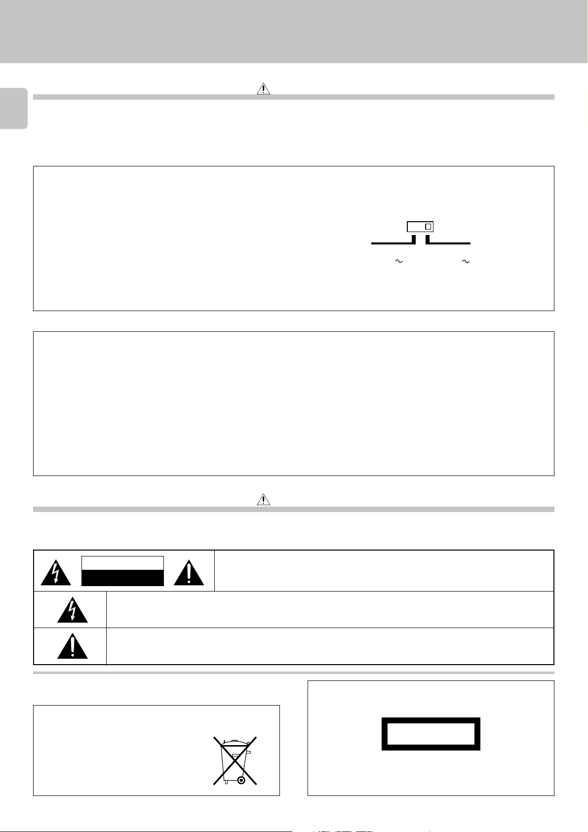
AC voltage selector switch
AC 110–
120V
Move switch lever to match your line voltage
with a small screwdriver or other pointed tool.
AC 220–
240V
For the United Kingdom
Factory fitted moulded mains plug
1. The mains plug contains a fuse. For replacement, use only a 13-Amp ASTA-approved (BS1362) fuse.
2. The fuse cover must be refitted when replacing the fuse in the moulded plug.
3. Do not cut off the mains plug from this equipment. If the plug fitted is not suitable for the power points in your home or the cable is too short to reach
a power point, then obtain an appropriate safety approved extension lead or adapter, or consult your dealer.
If nonetheless the mains plug is cut off, remove the fuse and dispose of the plug immediately, to avoid a possible shock hazard by inadvertent
connection to the mains supply.
IMPORTANT
The wires in the mains lead are coloured in accordance with the following code:
Blue : Neutral
Brown : Live
Do not connect those leads to the earth terminal of a three-pin plug.
Safety precautions
Caution : Read this section carefully to ensure safe operation.
WARNING : TO PREVENT FIRE OR ELECTRIC SHOCK, DO NOT EXPOSE THIS
APPLIANCE TO RAIN OR MOISTURE.
CAUTION
RISK OF ELECTRIC SHOCK
DO NOT OPEN
THE LIGHTNING FLASH WITH ARROWHEAD SYMBOL, WITHIN AN EQUILATERAL TRIANGLE, IS INTENDED TO ALERT
THE USER TO THE PRESENCE OF UNINSULATED “DANGEROUS VOLTAGE” WITHIN THE PRODUCT’S ENCLOSURE
THAT MAY BE OF SUFFICIENT MAGNITUDE TO CONSTITUTE A RISK OF ELECTRIC SHOCK TO PERSONS.
THE EXCLAMATION POINT WITHIN AN EQUILATERAL TRIANGLE IS INTENDED TO ALERT THE USER TO THE
PRESENCE OF IMPORTANT OPERATING AND MAINTENANCE (SERVICING) INSTRUCTIONS IN THE LITERATURE
ACCOMPANYING THE APPLIANCE.
CAUTION: TO REDUCE THE RISK OF ELECTRIC SHOCK, DO NOT REMOVE COVER (OR
BACK). NO USER-SERVICEABLE PARTS INSIDE, REFER SERVICING TO QUALIFIED
SERVICE PERSONNEL.
The marking of products using lasers
(Except for some areas)
REQUIREMENT BY NEDERLAND GAZETTE
Batteries are supplied with this product. When
they empty, you should not throw away. Instead,
hand them in as small chemical waste.
CLASS 1
LASER PRODUCT
The marking is located on the rear panel and says that the component uses laser beams that have been classified as Class 1. It means
that the unit is utilizing laser beams that are of a weaker class. There
is no danger of hazardous radiation outside the unit.
Page 3
DPF-3010/2010/1010 (En)
Unpacking
Unpack the unit carefully and make sure that all accessories are put aside so they will not be lost.
Examine the unit for any possibility of shipping damage. If your unit is damaged or fails to operate, notify your dealer immediately. If your unit was shipped to
you directly, notify the shipping company without delay. Only the consignee (the person or company receiving the unit) can file a claim against the carrier for
shipping damage.
We recommend that you retain the original carton and packing materials for use should you transport or ship the unit in the future.
Keep this manual handy for future reference.
Special features
Advanced technologies incorporated in pursuit of
improved sound quality and stability
¶ D.R.I.V.E. (Dynamic Resolution Intensive Vector Enhancement) IC is built in for drastic
reduction of distortion at small signal level. (DPF-3010 only)
¶ High-performance 1-bit D/A converter achieving a 20-bit resolution. (DPF-3010 only)
Convenient features for dubbing CD onto tape
¶ CD peak search for setting the recording level that does not cause distortion. (
¶ Edit function for rearranging tracks according to the tape length so that no music is interrupted
in the middle. *
Easy operation functions
¶ Auto space function. %
¶ Easy operation functions allow systematic operation with other KENWOOD components
connected through the system control connection. 8
3
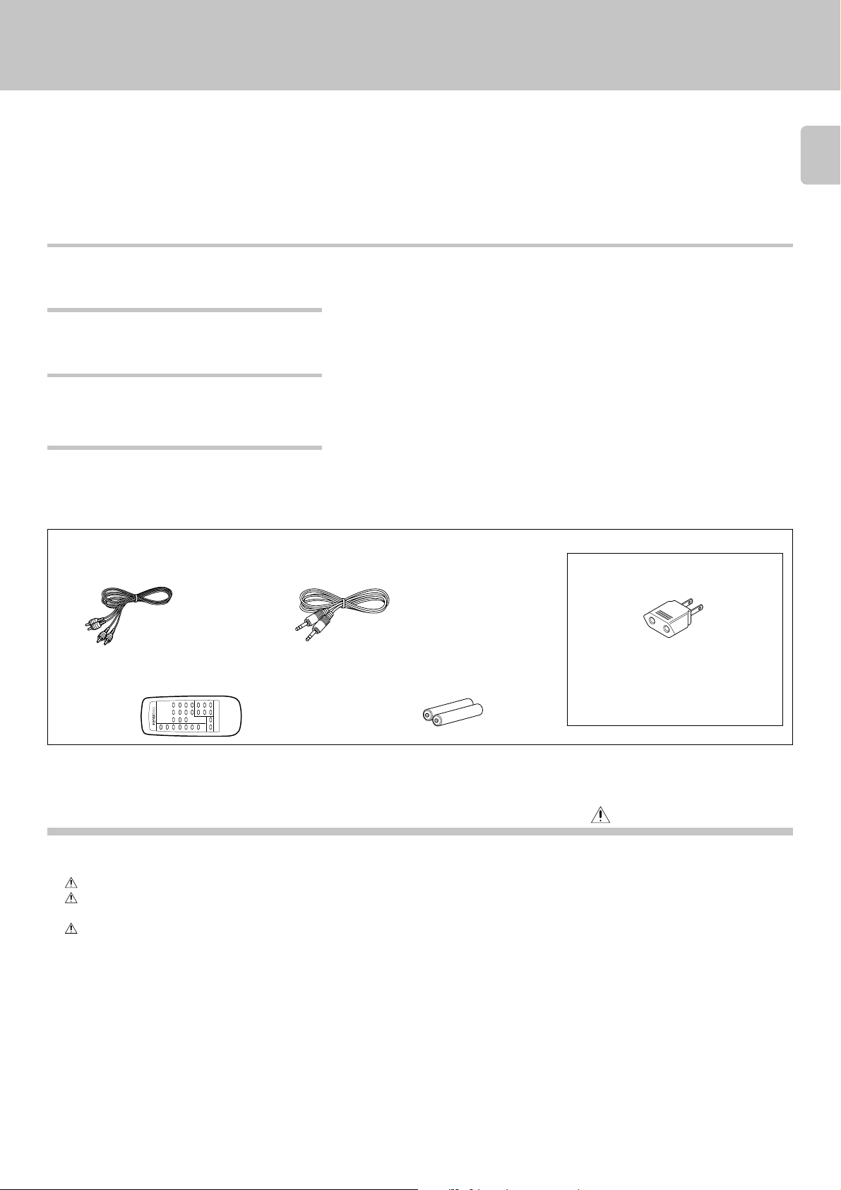
Accessories
Audio cord ........................ (1) System control cord ............(1)
Remote control unit ......... (1) Batteries (R6/AA) .............. (2)
(DPF-3010/DPF-2010 only) (DPF-3010/DPF-2010 only)
RC-P0305
REMOTE CONTROL UNIT
Contents
Introduction.................................................................. 2
Before applying power ................................................ 2
Safety precautions ....................................................... 2
Special features ................................................................... 3
IMPORTANT SAFEGUARDS........................................ 4
System connections .................................................... 6
To use the headphone......................................................... 7
Maintenance................................................................. 9
Controls and indicators ............................................. 10
Operation of remote control unit ............................. 11
Normal play (TRACK mode)...................................... 12
Playing tracks in order from track No.1 .......................... 12
Playback from desired track .............................................13
Skipping tracks ..................................................................13
Searching ........................................................................... 13
Time display on CD player (TIME DISPLAY) .................... 13
AC plug adaptor .............. (1)
Use to adapt the plug on the power cord
to the shape of the wall outlet.
(Accessory only for regions where use is
necessary.)
Caution: Read the pages marked carefully to ensure safe operation.
Programmed play (PGM mode)................................ 14
To check or change the programmed tracks .................. 15
To add a track to the program ......................................... 15
To clear tracks from the program .................................... 15
Repeated playback .................................................... 16
To repeat only the programmed tracks........................... 16
To repeat the entire disc ................................................... 17
Editing......................................................................... 18
Playing or recording the edited contents ....................... 18
To check the edited contents ........................................... 19
To clear the edited contents............................................. 19
Peak search ........................................................................ 19
Playback in random order (Random playback) ....... 20
Timer operations........................................................ 21
In case of difficulty..................................................... 22
Specifications ............................................................. 23
Page 4
IMPORTANT SAFEGUARDS
Caution : Read this page carefully to ensure
safe operation.
DPF-3010/2010/1010 (En)
Please read all of the safety and operating instructions
before operating this appliance. Adhere to all warnings on
4
the appliance and in the instruction manual. Follow all the
safety and operating instructions. These safety and
operating instructions should be retained for future
reference.
1. Power sources – The appliance should be connected to
a power supply only of the type described in the instruction
manual or as marked on the appliance. If you are not sure
of the type of power supply to your home, consult your
appliance dealer or local power company. For appliances
intended to operate from battery power, or other sources,
refer to the instruction manual.
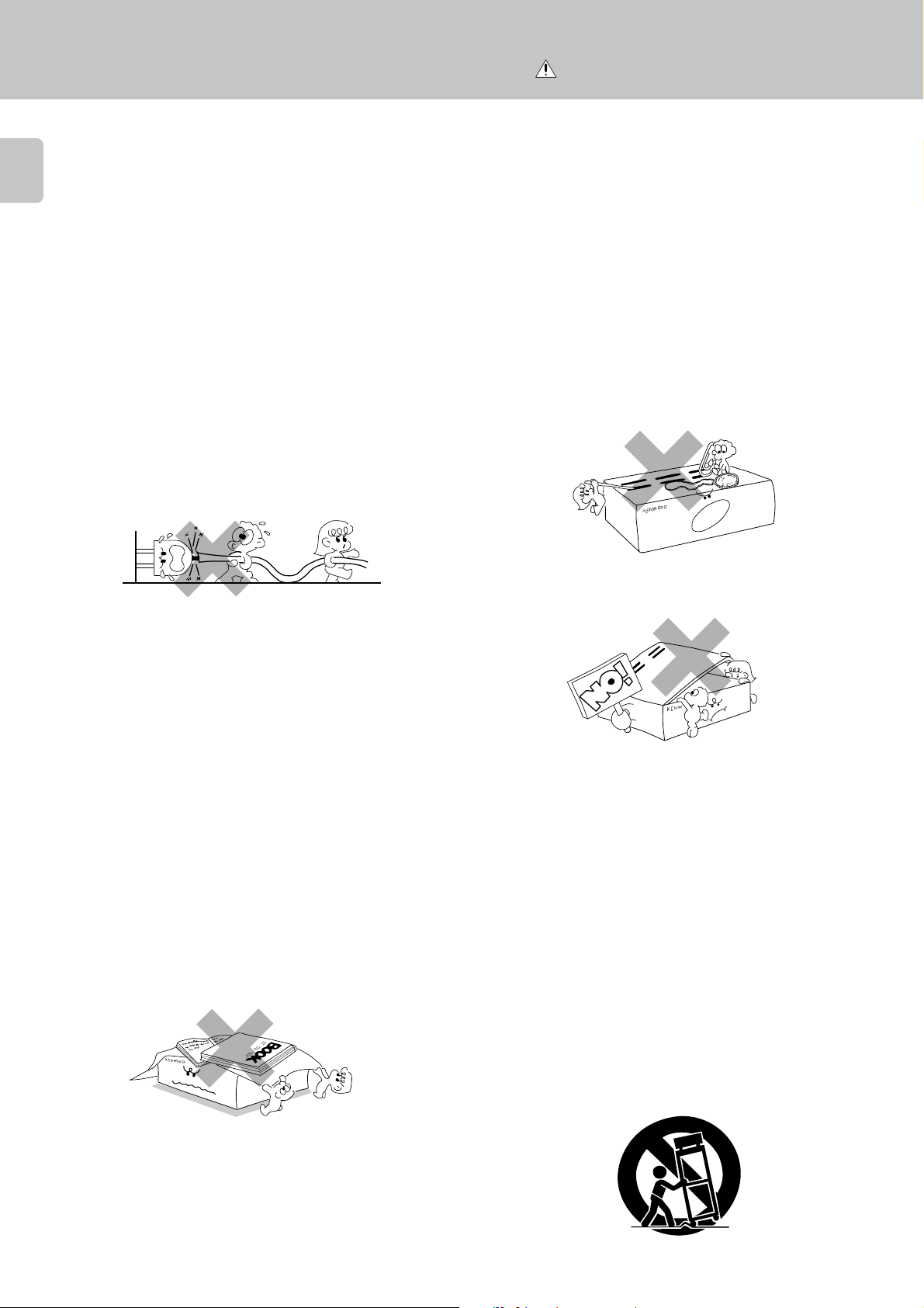
2. Power-cord protection – Power-supply cords should
be routed so that they are not likely to be walked on
or pinched by items placed upon or against them,
pay particular attention to cords at plugs, convenience
receptacles, and the point where they exit from the
appliance.
Never pull or stretch
the cord.
3. CAUTION – Polarization – This appliance may be
equipped with a polarized alternating-current line plug (a
plug having one blade wider than the other). This plug will
fit into the power outlet only one way. This is a safety
feature. If you are unable to insert the plug fully into the
outlet, try reversing the plug. If the plug should still fail to
fit, contact your electrician to replace your obsolete outlet.
Do not defeat the safety purpose of the polarized plug.
4. Ventilation – Slots and openings in the cabinet are
provided for ventilation and to ensure reliable operation of
the appliance and to protect it from overheating, and these
openings must not be blocked or covered. The appliance
should be situated so that its location or position does not
interfere with its proper ventilation.
To maintain good ventilation, do not put records or a tablecloth on the appliance. Place the appliance at least 10 cm
away from the walls.
Do not use the appliance on a bed, sofa, rug or similar
surface that may block the ventilation openings. This
appliance should not be placed in a built-in installation such
as a bookcase or rack unless proper ventilation is provided
or the manufacturer’s instructions have been adhered to.
6. Temperature – The appliance may not function
properly if used at extremely low, or freezing
temperatures. The ideal ambient temperature is
above +5°C (41°F).
7. Heat – The appliance should be situated away from
heat sources such as radiators, heat registers, stoves,
or other appliances (including amplifiers) that produce
heat.
8. Electric shock – Care should be taken so that objects
do not fall and liquid is not spilled into the enclosure
through openings. If a metal objects, such as a hair
pin or a needle, comes into contact with the inside of
this appliance, a dangerous electric shock may result.
For families with children, never permit children to
put anything, especially metal, inside this appliance.
9. Enclosure removal – Never remove the enclosure.
If the internal parts are touched accidentally, a serious
electric shock might occur.
10.Magnetic fields – Keep the appliance away from
sources of magnetic fields such as TV sets, speaker
systems, radios, motorized toys or magnetized
objects.
11.Cleaning – Unplug this appliance from the wall
outlet before cleaning. Do not use volatile solvents
such as alcohol, paint thinner, gasoline, or benzine,
etc. to clean the cabinet. Use a clean dry cloth.
12.Accessories – Do not place this appliance on an unstable
cart, stand, tripod, bracket, or table. The appliance may fall,
causing serious injury to a child or adult, and serious
damage to the appliance. Use only with a cart, stand,
tripod, bracket, or table recommended by the manufacturer,
or sold with the appliance. Any mounting of the appliance
should follow the manufacturer’s instructions, and should
use a mounting accessory recommended by the
manufacturer. An appliance and cart combination should
be moved with care. Quick stops, excessive force, and
uneven surfaces may cause the appliance and cart
combination to overturn.
5. Water and moisture – The appliance should not be
used near water - for example, near a bathtub,
washbowl, kitchen sink, laundry tub, in a wet
basement, or near a swimming pool, etc.
Page 5
Caution : Read this page carefully to ensure safe operation.
DPF-3010/2010/1010 (En)
13.Lightning – For added protection for this appliance during
a lightning storm, or when it is left unattended and unused
for long periods of time, unplug it from the wall outlet and
disconnect the antenna or cable system. This will prevent
damage to the appliance due to lightning and power-line
surges.
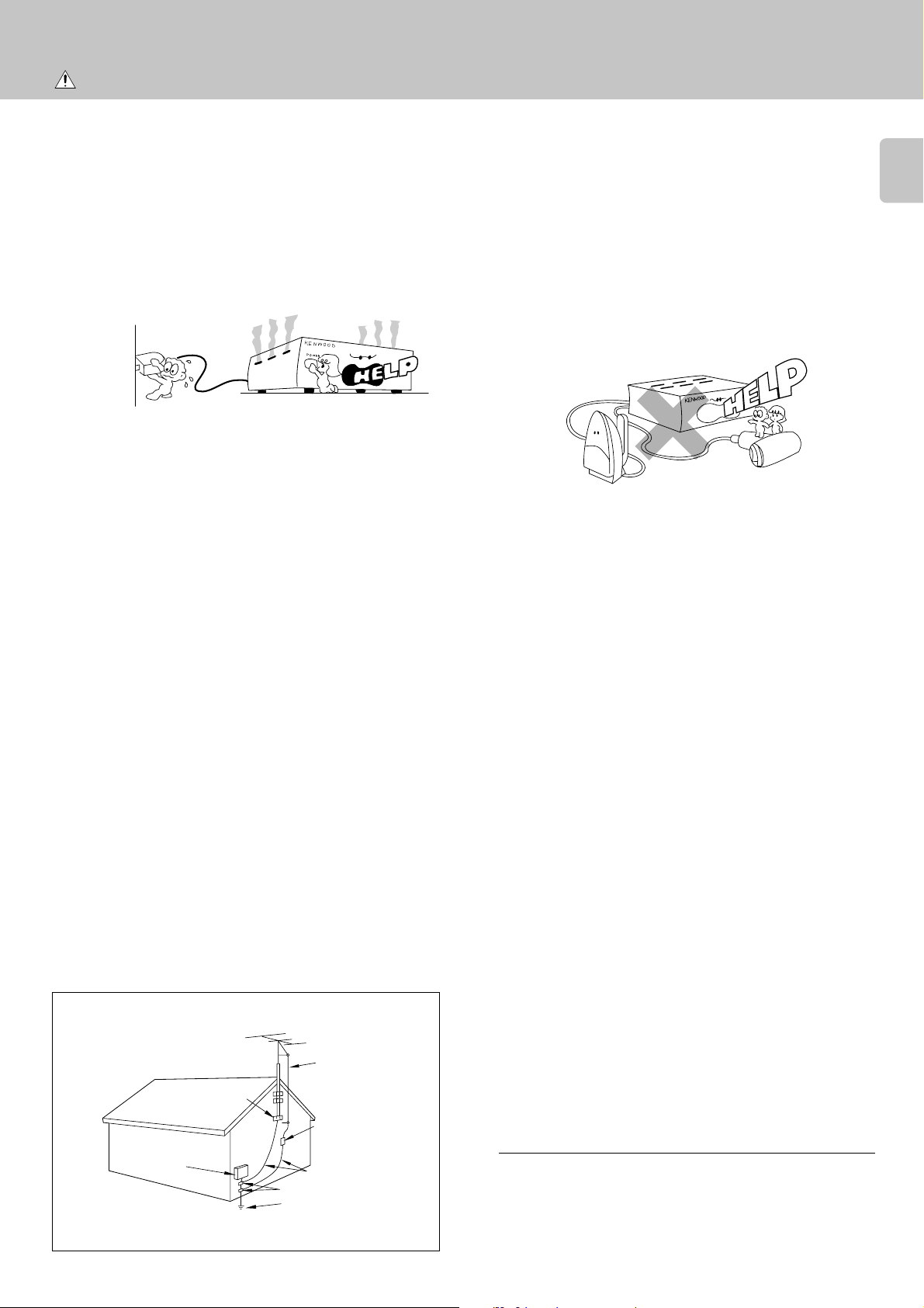
14.Abnormal smell – If an abnormal smell or smoke is
detected, immediately turn the power OFF and unplug
the appliance from the wall outlet. Contact your dealer or
nearest service center.
15.Damage requiring service – The appliance should
be serviced by qualified service personnel when:
A. The power-supply cord or the plug has been
damaged.
B. Objects have fallen, or liquid has been spilled into
the appliance.
C. The appliance has been exposed to rain or water.
D. The appliance does not appear to operate normally
by following the instruction manual. Adjust only those
controls that are covered by the instruction manual as an
improper adjustment of other controls may result in damage
and will often require extensive work by a qualified
technician to restore the appliance to its normal operation.
E. The appliance has been dropped, or the enclosure
damaged.
F. The appliance exhibits a marked change in performance.
16.Servicing – The user should not attempt to service
the appliance beyond that described in the instruction
manual. All other servicing should be referred to
qualified service personnel.
17.Outdoor antenna grounding – If an outside antenna
is connected to the appliance, be sure the antenna
system is grounded so as to provide some protection
against voltage surges and built up static charges.
Article 810 of the National Electrical Code ANSI/
NFPA 70, provides information with respect to proper
grounding of the mast and supporting structure,
grounding of the lead-in wire to an antenna discharge
unit, size of grounding conductors, location of antenna
discharge unit, connection to grounding electrodes,
and requirements for the grounding electrode. See
Figure.
18.Power lines – An outside antenna system should not be
located in the vicinity of overhead power lines or other
electric light or power circuits, or where it can fall into such
power lines or circuits. When installing an outside antenna
system, extreme care should be taken to keep from
touching such power lines or circuits as contact with them
might be fatal.
19.AC outlets – Do not connect other audio equipment
with a power consumption larger than that specified
to the AC outlet on the rear panel. Never connect
other electrical appliances, such as an iron or toaster,
to it to prevent fire or electric shock.
20. Overloading – Do not overload wall outlets, extension
cords, or integral convenience receptacles as this can
result in a risk of fire or electric shock.
21. Attachment – Do not use attachments not recommended
by the appliance manufacturer as they may cause hazards.
22. Replacement parts – When replacement parts are required,
be sure the service technician has used replacement parts
specified by the manufacturer or have the same
characteristics as the original parts. Unauthorized
substitutions may result in fire, electric shock, or other
hazards.
23. Safety check – Upon completion of any service or repairs
to this appliance, ask the service technician to perform
safety checks to determine that the appliance is in proper
operating condition.
5
EXAMPLE OF ANTENNA GROUNDING AS PER
NATIONAL ELECTRICAL CODE
GROUND
CLAMPS
ELECTRIC
SERVICE
EQUIPMENT
NEC – NATIONAL ELECTRICAL CODE
ANTENNA
LEAD IN WIRE
ANTENNA
DISCHARGE UNIT
(NEC SECTION 810-20)
GROUNDING CONDUCTORS
(NEC SECTION 810-21)
GROUND CLAMP
POWER SERVICE GROUNDING
ELECTRODE SYSTEM
(NEC ART 250, PART H)
Notes:
1. Item 3 is not required except for grounded or polarized equipment.
2. Item 17 and 18 are not required except for units provided with
antenna terminals.
3. Item 17 complies with UL in the U.S.A.
Page 6
System connections
DPF-3010/2010/1010 (En)
Caution:
Do not plug in the power lead until all connections are com-
6
pleted.
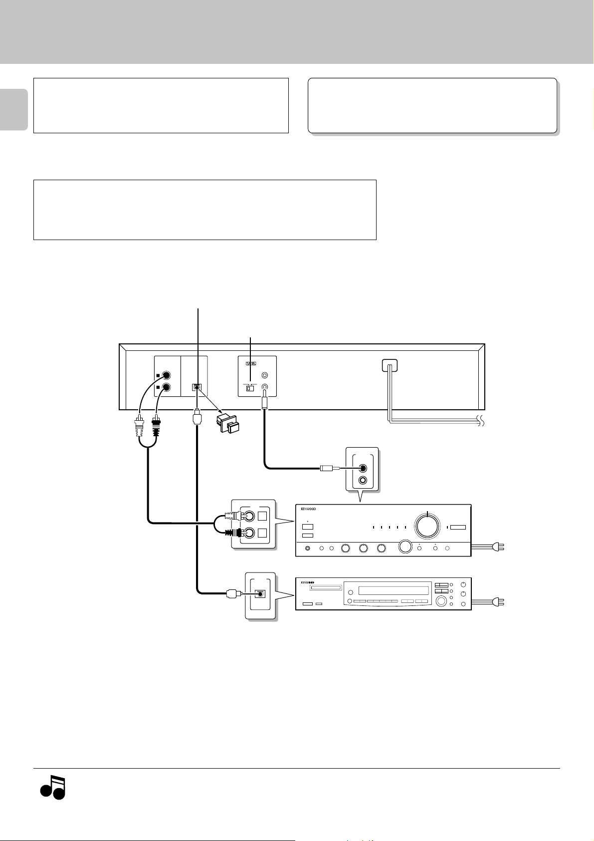
Make connections as shown below.
When connecting the related system components, refer also to the
instruction manuals of the related components.
Caution regarding placement
To maintain proper ventilation, be sure to leave a space around the unit (from the largest outer
dimensions including projections) equal to, or greater than, shown below.
Left and right panels: 10 cm Rear panel: 10 cm
DIGITAL OUTPUT jack
(DPF-3010/DPF-2010 only)
SL 16/XS8 switch
OUTPUT
L
R
DIGITAL
OUTPUT
OPTICAL
SYSTEM CONTROL
SL 16 XS-8
ƒ
8
Malfunction of microcomputer
If operation is not possible or erroneous display appears even
though all connections have been made properly, reset the
microcomputer referring to “In case of difficulty”.
™
Remove the
protection cap
when using the
DIGITAL OUTPUT
(OPTICAL) jack.
Audio cord
Commercially-available
optical fiber cable
System control cord
CD
L
R
DIGITAL
INPUT
OPTICAL
Amplifier
MD recorder
SYSTEM
CONTROL
To AC outlet
To wall AC outlet
To AC outlet
Notes
Notes
1. Connect all cords firmly. If connections are loose there could be loss of sound or noise produced.
2. When plugging and unplugging connection cords, be sure to first remove the power cord from the AC outlet. Plugging/unplugging
connection cords without removal of the power cord can cause malfunctions or damage to the unit.
Page 7
DPF-3010/2010/1010 (En)
Connection to a general-use amplifier
Use the provided audio cords to connect the OUTPUT jacks of this unit to the CD input jacks (or AUX jacks) of the amplifier.
Connection to digital amplifier or MD (only for DPF-3010/2010)
Connect the DIGITAL OUTPUT (OPTICAL) jack to the digital input jack
of the amplifier, DAT recorder, MD recorder, etc., using an optical
fiber cable which are commercially available in audio stores.
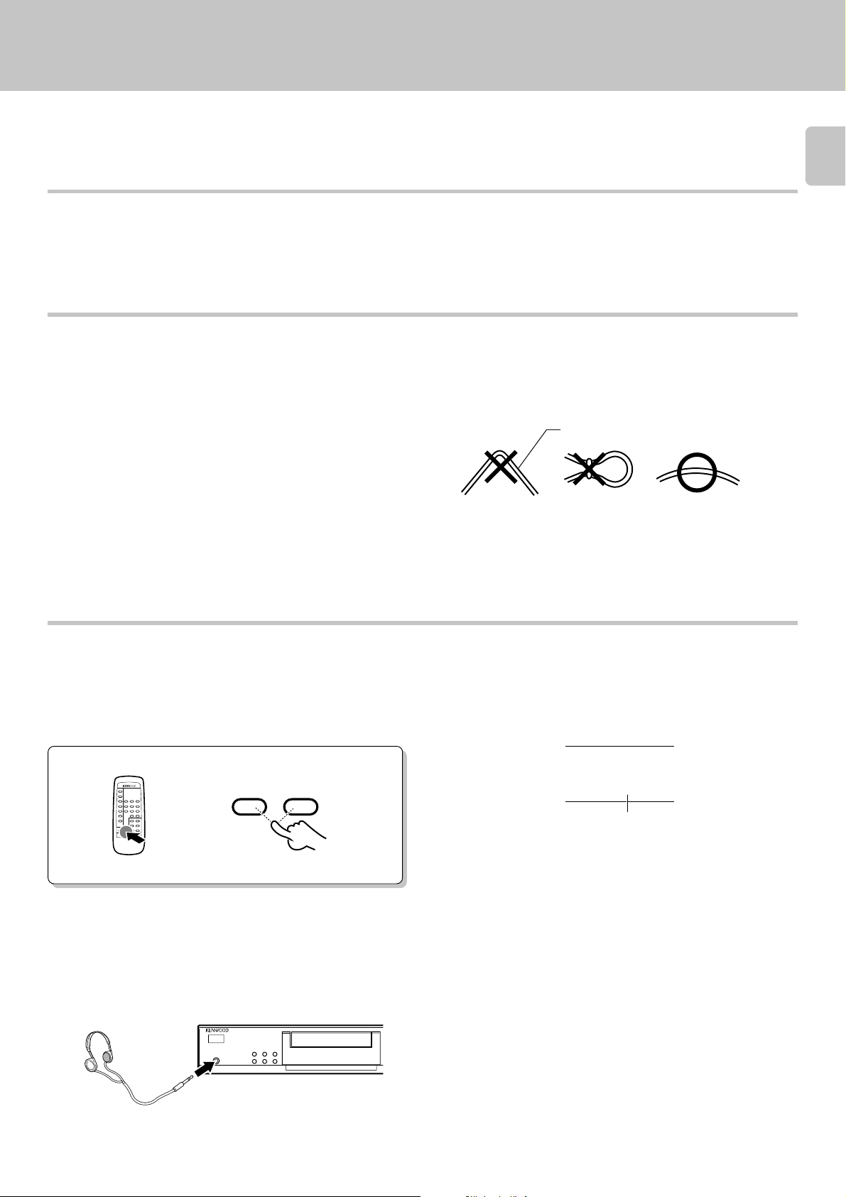
÷When using an optical fiber cable to connect this unit to a digital
amplifier, insert the plug straight into the jack until a snap sound is
heard.
÷Be careful not to bend, coil, or bundle the optical fiber cable.
÷Optical fiber cables available on the market may not always be able to
be used with this player. If your cord cannot be used with this unit,
consult the store from which you purchased the cord or your nearest
dealer.
Optical fiber cable
7
Adjusting the output levels of the output jacks
and headphone output (only for DPF-3010/2010)
The OUTPUT level (UP/DOWN) keys of the remote control unit can
adjust the output levels from the LINE/OUT jacks and PHONES jack
(DPF-3010 only) of the unit.
OUTPUT
DOWN UP
REMOTE CONTROL UNIT
RC-P0305
To use the headphone (only for DPF-3010)
Connect a stereo headphone to the PHONES jack of the CD player.
Adjust the sound volume using the remote control unit.
SINGLE TIME
_
12 db
Output level
÷It is not favorable for the sound quality to decrease the output level from
this unit too much. Use these keys for coordination with other line
levels.
÷Adjusting the headphone output level also changes the LINE/OUT
level. Do not adjust the output level from this unit particularly during
recording.
÷Please note that the sound output is at the maximum level when the
power is turned on.
Page 8
8
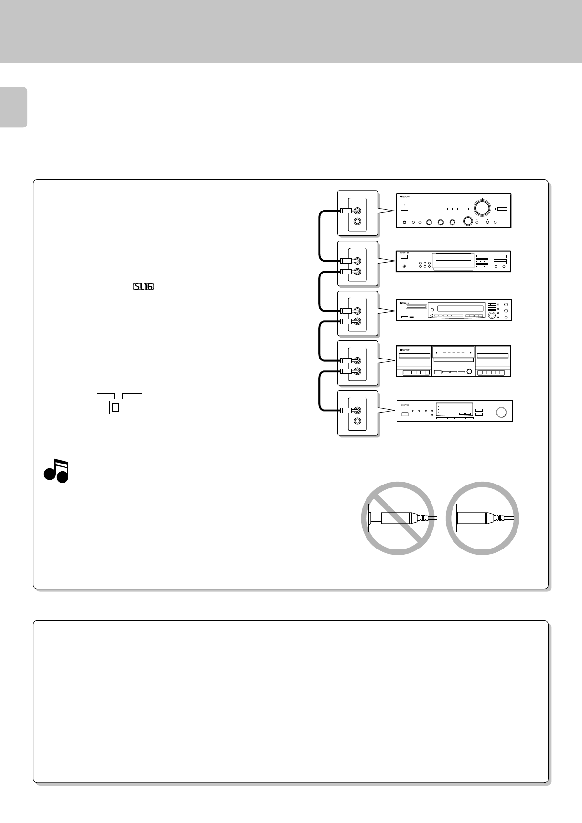
SYSTEM CONTROL CONNECTIONS
Connecting system control cords after connecting a KENWOOD
audio component system lets you take advantage of convenient
system control operations.
There are two KENWOOD system control modes. Make connections according to the groups of terminal symbols shown below.
SYSTEM
CONTROL
SYSTEM
CONTROL
DPF-3010/2010/1010 (En)
[XS8] Mode : lets you combine F, f, and ƒ terminals
[SL16] Mode : for
terminals only
This unit is compatible with both [XS8] and [SL16] modes.
÷ When all units in system control connection are set to [XS8]
mode, set the SYSREM CONTROL selector switch on the rear
to the [XS8] side and connect.
÷ When all units in system control connection are set to [SL16]
mode, set the SYSREM CONTROL selector switch on the rear
to the [SL16] side and connect.
SL16 XS 8
SYSREM CONTROL
selector switch
j
÷Do this operation after completing all connections.
(Ensure that the unit is set to STANDBY mode.)
1. [SL16] equipment cannot be combined with [XR], [XS], and [XS8]
Notes
Notes
equipment for system operations. If your equipment consists of this
kind of combination, please do not connect any system control cords.
Even without system control cords, normal operations can be carried out without affecting performance.
2. If your amp or receiver does not have a system control terminal, do
not connect any system control cords to the system control terminals
on the other components.
3. Do not connect system control cords to any components other than
those specified by Kenwood. It may cause a malfunction and damage
your equipment.
4. Be sure the system control plugs are inserted all the way in to the
system control terminals.
SYSTEM
CONTROL
SYSTEM
CONTROL
SYSTEM
CONTROL
SYSTEM CONTROL OPERATIONS
Remote Control
Lets you operate this unit with the system remote control unit supplied with the amplifier or receiver.
Automatic Operation (Except [XR] equipment)
Automatically switches the input selector on the amplifier or receiver when you start playback from this unit.
Synchronized Recording (Except [XR] equipment)
Lets you synchronize recording with the start of playback when recording from CD. Also, the simple CCRS operation lets you make great recordings
from CD.
See the operating instructions supplied with your cassette deck and MD recorder for details.
Page 9

Maintenance
Disc handling precautions
Handling
Hold compact discs so that you do not
touch the playing surface.
Sticker
Label side
Playing
side
Sticky paste
÷Do not attach paper or tape to either
the playing side or the label side of
compact discs.
÷The paste left on the label surface after
a sticker has been peeled off is a factor
which may cause malfunction. If the
surface is sticky due to remaining paste,
be sure to clean it with alcohole before
use.
DPF-3010/2010/1010 (En)
Cleaning
If fingerprints or foreign matter become
attached to the disc, lightly wipe the
disc with a soft cotton cloth (or similar)
from the center of the disc outwards,
in a radial manner.
Storage
When a disc is not to be played for a
long period of time, remove it from the
CD player and store it in its case.
9
Caution on disc used
Discs which can be played with this unit
Cleaning
Do not use volatile solvents such as alcohol, paint thinner, gasoline,
or benzine, etc. to clean the cabinet. Use a clean dry cloth.
Do not use contact cleaners because it could cause a malfunction.
Be specially careful against contact cleaners containing oil, for they
may deform the plastic components.
Never play a cracked or warped disc.
During playback, the disc rotates at high speed in the player.
Therefore, to avoid danger, never use a cracked or deformed disc or a
disc repaired with tape or adhesive agent.
Do not use cleaning discs.
Please do not use commercially available cleaning discs, they may damage the internal mechanism.
CD (12 cm, 8 cm), CDV (only the audio part)
÷With CD-G (CD Graphics) discs, this unit can play only the audio.
Note related to transportation and movement
Before transporting or moving this unit, carry out the following
operations.
1. Turn the power ON but do not load a disc.
2. Verify that the display shown appears.
TRACK
n
d1 SC
o
1
2
6
7
11
12
17
16
13
18
5
4
3
10
9
8
15
14
20
19
CD accessories
The CD accessories (stebilizer, protection sheet, protection ring, etc.)
which are marketed for improving the sound quality or protecting discs
as well as the disc cleaner should not be used with this system because they may cause malfunction.
Caution on condensation
Condensation (of dew) may occur inside the unit when there is a
great difference in temperature between this unit and the outside.
This unit may not function properly if condensation occurs. In this
case, leave the unit for a few hours with the power left ON, and
restart the operation after the condensation has dried up.
3. Wait a few seconds and set the unit to STANDBY mode.
Be specially cautious against condensation in a following circumstance:
When this unit is carried from a place to another across a large
difference in temperature, when the humidity in the room where this
unit is installed increases, etc.
Page 10

Controls and indicators
DPF-3010/2010/1010 (En)
10
TRACK mode indicator
Program mode indicator
The figure shows an example
for the DPF-3010
1
ON/STANDBY
PHONES
TRACK
PGM
Pause indicator
Play indicator
REPEAT indicator
Program
check indicator
REPEAT
TRACK
NO.
8
8
Play track No. indicator
CCRS indicator
EDIT indicator
CCRS
EDIT
SINGLE TIME
TOTAL TIME
P.C.
_
88 88
:
TIME indicator,
program No.
Output level indicator
SINGLE TIME indicator
TOTAL TIME indicator
5
4
3
2
1
10
9
8
7
6
11
16
13
12
18
17
Music calender
14
19
15
20
DISPLAY
234 5 6 78
0
1 2 3
PEAK SEARCHCHECKP.MODE
TIME DISPLAY
CLEAREDIT
4 5 6
7 8 9
0 +10
STOP PLAY/PAUSE
76
4
¢
1¡
REPEAT RANDOM
90!@#$ %^&
The keys with the same name as those on the remote control
unit operate the same way as the remote control unit.
1 ON/STANDBY ( ) switch @
Turns the unit ON/STANDBY.
2 P.MODE key $
Press for program playback.
3 CHECK key %(
Press to display the programmed contents in order.
4 PEAK SEARCH key (
5 Open/Close key (0) @
Opens and closes the disc tray.
6 STOP key (7) @
7 PLAY/PAUSE key (6) @
Each time the key is pressed, playback and pause switch
each other.
8 Skip keys (4,¢) #
Press to skip to the beginning of another track.
9 PHONES jack (DPF-3010 only) 7
Use to connect (optional) headphones.
*
0 EDIT key *
Press to select the edit recording mode.
! CLEAR key %(
Press to clear the contents of a program.
@ TIME DISPLAY key #
Press to switch the time display mode.
# Remote control light sensor !
(DPF-3010/2010 only)
$ Disc tray
Load the disc to be played back.
% Numeric keys #
Use the numeric keys to select the desired track.
^ REPEAT key ^
Press to start repeated playback.
& RANDOM key )
Press to start random playback.
*
Search keys (1,¡) #
Fast forwards or fast reverses the track.
@
Page 11

Operation of remote control unit
The keys with the same name as those on the main unit operate the same way as the main unit.
The keys marked * are provided only on the remote control unit.
(DPF-3010/DPF-2010 only)
DPF-3010/2010/1010 (En)
DISC SELECTORDISC SELECTOR
1 2
4
5
12
45
7
4
OUTPUT
REMOTE CONTROL UNIT
1
RC-P0305
3
DISC SKIPDISC SKIP
3
6
9
6
¢
¡
1
2
RANDOM
REPEAT
P.MODE
TIME
DISPLAY
EDIT 7 8
CHECK 0 +10
CLEAR
DOWN UP
Loading batteries
1 Program-related and other keys
RANDOM key )
REPEAT key ^
P.MODE key $
TIME DISPLAY key #
EDIT key *
3
CHECK key %(
CLEAR key %(
4
Model: RC-P0305
Infrared ray system
*2 OUTPUT (DOWN, UP) key 7
11
))
3 Numeric keys (
1 ~
11
) ,
))
00
0
00
) #
4 Basic function keys
Skip keys (4,¢) #
Search keys (1,¡) #
Stop key (7) @
Play/Pause key (6) @
11
1 Remove the cover. 2 Insert batteries. 3 Close the cover.
2
1
÷ Insert two AA-size (R6) batteries as
indicated by the polarity marking.
2
Operation
After plugging in the power cord, press the ON/STANDBY
) switch of the main unit to turn the unit ON. When the
(
unit is turned ON, press the key of the function to be
operated.
÷When pressing more than one remote control key successively,
press the keys securely by leaving an interval of 1 second or more
between keys.
Remote control
light sensor
306m30
REMOTE CONTROL UNIT
RC-P0305
1
Operating range
(Approx.)
Notes
Notes
1. The supplied batteries are intended for use in operation checks. Therefore, their lives may be shorter than ordinary batteries.
2. When the remote-controllable distance gets shorter than before, replace both batteries with new ones.
3. Malfunction may occur if direct sunlight or the light of a high-frequency lighting fluorescent lamp enters the remote control light sensor.
In such a case, change the system installation position to prevent the malfunction.
Page 12

Normal play (TRACK mode)
TRACK
TRACK
NO.
SINGLE TIME
6172839410
5
0:1
000
TRACK
TRACK
NO.
SINGLE TIME
6172839410
5
0:1
005
Use the following procedure to play a CD in the original order
of tracks from track No. 1.
12
: Keys and control used in the operations described on this page.
Playing tracks in order from track No. 1
Press the ON/STANDBY switch to ON.
1
ON/STANDBY
÷Playback starts when a disc has been loaded.
DPF-3010/2010/1010 (En)
The figure shows an example for the DPF-3010
76
4
1¡
¢
Load a disc.
2
Start playback.
3
Open the tray.
1
Place a disc.
2
Disc tray
Close the tray.
3
0
0
PLAY/PAUSE
6
Label side
76
4
¢
1¡
÷Do not touch the played side of disc.
÷Loading two discs together will cause malfunctioning.
÷Place the disc properly along the groove on the tray. (If the disc is not
placed horizontally, malfunction will result.)
÷A single CD (8 cm disc) can also be played.
÷Ordinary CD single (8 cm) disc adapters sold in audio stores cannot be
used with this unit.
Lights up.
The track Nos. recorded on the CD are displayed.
÷After a few seconds, play starts from the track No. 1.
Elapsed time of track being played
To pause playback
÷Each press pauses and plays the CD alternately.
PLAY/PAUSE
6
TRACK
Lights up.
Track NO. being played
To stop playback
STOP
7
Page 13

Playback from desired track
DPF-3010/2010/1010 (En)
Skipping tracks
To skip
backward
Searching
1 2 3
4 5 6
7 8 9
0
4¢
+
10
To skip
forward
Press the numeric keys as shown below....
To enter track No. 23 : 003
To enter track No. 40 : 0000)
÷Playback starts from the selected track and continues on the subse-
quent tracks.
÷The track in the direction of the pressed key is skipped, and the selected
track will be played from the beginning.
÷When the 4 key is pressed once during playback, the track being
played will be played from the beginning.
13
Backward
search
1¡
Forward
search
÷Playback starts from the position where the key is released.
Time display on CD player (TIME DISPLAY)
Each press of the TIME DISPLAY key changes the displayed contents.
1
TIME DISPLAY
2
3
4
÷Only the display 1 and 2 will be displayed in RANDOM and EDIT
modes.
SINGLE TIME
: Elapsed time of track being played (SINGLE TIME
:231
SINGLE TIME
TOTAL TIME
2
TOTAL TIME
3
lights up.)
: Remaining time of track being played (SINGLE
:372_
TIME lights up.)
: Elapsed time of entire disc (TOTAL TIME lights
:453
up.)
: Remaining time on entire disc (TOTAL TIME lights
:156_
up.)
Page 14

Programmed play (PGM mode)
TRACK
NO.
PGM
01
Use the following procedure to program desired tracks in a
desired order. (up to 20 tracks)
14
Preparation
Press so that the “PGM” indicator lights.
1
÷ Load a disc in the CD player. @
DPF-3010/2010/1010 (En)
The figure shows an example for the DPF-3010
76
4
¢
1¡
: Keys and control used in the operations described on this page.
Program desired tracks.
2
1 Select the desired track No.
2 Set the entry.
3 Repeat steps 1 and 2 above.
Do this operation in the stop mode.
P.MODE
Press the numeric keys as shown below....
To enter track No. 25: 005
1 2 3
4 5 6
7 8 9
0
Go to step 2 within 5 seconds.
P.MODE
+
10
Lights up.
Displays the entered program No.
for a few seconds.
TRACK
NO.
02
÷Up to 20 tracks can be programmed. When “FULL” is displayed, no
more tracks can be programmed.
÷If you make a mistake, press the CLEAR key and enter the track No.
from the beginning.
÷When the total playing time of the programmed tracks exceeds 100
minutes, the remaining time on the disc will not be displayed any more.
P_ 01
0
Displays the total playing time
of the programmed tracks.
TRACK
NO.
_
2
16 42
TOTAL TIME
:
Start playback.
3
To stop playback
PLAY/PAUSE
6
STOP
7
÷When the 4 or ¢ key is pressed during playback, the track will be
skipped in the direction of the pressed button.
÷When the 4 key is pressed once during playback, the play position
returns to the beginning of the current track being played.
÷The programmed contents remain in memory.
Page 15

Auto space function
During programming of tracks, a non-recorded space of a few
seconds will be automatically created between tracks. By recording
tracks with these spaces on tape, the search and repeat play
operations of tape using the DPSS function (which works by
searching the non-recorded spaces) can be performed reliably.
÷Even when the performances of two tracks are continuous (which
occurs with classical or live recording music), the spaces will be
created if they have different track numbers.
To check or change the programmed tracks
1 Press the CHECK key.
CHECK
Press until the track No. to
be changed is displayed.
PGM
TRACK
NO.
06
Lights up.
P.C.
P_ 02
DPF-3010/2010/1010 (En)
15
3
6
2 Select the new track No.
1 2 3
4 5 6
7 8 9
0
+
10
3 Set the entry.
P.MODE
To add a track to the program
1 Select the desired track No.
1 2 3
4 5 6
7 8 9
0
2 Press the P.MODE key.
+
10
÷Perform only step 1 to simply check the program.
÷Each time the key is pressed, the program No. (P-No.) and the track No.
on CD are displayed.
÷The previous display resumes in a few seconds.
÷Press it while the “P.C.” indicator is lit.
÷The track being played cannot be changed.
÷When a track No. is selected, the track will be added to the end of the
existing program.
To clear tracks from the program
Press to clear tracks from the end.
CLEAR
To clear all track.
P.MODE
÷Each time the key is pressed, the last track in the program is cleared.
÷The tracks which are programmed earlier than the track being played
cannot be cleared.
÷Selected tracks can be also completely cleared just by operating the 0
key.
÷The entire program is cleared.
Page 16

Repeated playback
TRACK
NO.
PGM
01
DPF-3010/2010/1010 (En)
Preparation
16
™
÷ Load a disc in the CD player.
To repeat only the programmed tracks
Press so that the "PGM" indicator lights.
1
P.MODE
Do this operation in the stop mode.
Select the desired track No.
2
Press the numeric keys as shown below...
To enter track No. 25:
1 2 3
4 5 6
7 8 9
0
005
+
10
@
The figure shows an example for the DPF-3010
76
4
¢
1¡
: Keys and control used in the operations described on this page.
Lights up.
÷All of the programmed tracks will be repeated.
÷In case only one track is programmed, only that track will be repeated.
÷Up to 20 tracks can be programmed. When “
FULL” is displayed, no
more tracks can be programmed.
Go to step 3 within 5 seconds.
Set the entry.
3
Repeat steps 2 and 3 above.
4
Switch REPEAT ON.
5
Start playback.
6
PLAY/PAUSE
To cancel repeated playback
Press the REPEAT key again.
P.MODE
REPEAT
6
REPEAT
PGM
PGM
Lights up.
REPEAT
TRACK
NO.
01
Goes off.
REPEAT
TRACK
NO.
01
Page 17

DPF-3010/2010/1010 (En)
TRACK
TRACK
NO.
01
TRACK
TRACK
NO.
REPEAT
01
To repeat the entire disc
Press so that the “TRACK” indicator
1
lights.
P.MODE
Switch REPEAT ON.
2
REPEAT
The figure shows an example for the DPF-3010
76
4
1¡
: Keys and control used in the operations described on this page.
Lights up.
Lights up.
17
¢
Start playback.
3
PLAY/PAUSE
6
To cancel repeated playback
Press the REPEAT key again.
REPEAT
TRACK
Goes off.
REPEAT
TRACK
NO.
01
Page 18

Editing
The following procedure allows to record a CD within the
specified tape length so that no music is interrupted in the
middle at the ends of sides A and B.
18
DPF-3010/2010/1010 (En)
The figure shows an example for the DPF-3010
Preparation
Light the “EDIT” indicator.
1
Enter the recording time of the tape.
2
÷ Load a disc in the CD player.
Do this operation in the stop mode.
Go to step 2 within 5 seconds.
If more than 5 seconds have elapsed,
press the key again.
EDIT
1 2 3
4 5 6
7 8 9
0
@
: Keys and control used in the operations described on this page.
Lights up.
PGM
Lights up.
EDIT
76
4
¢
1¡
C_ __
Blinks.
Press the numeric keys as shown below.
30-minute tape : 000)
46-minute tape : 00006
+
10
÷Recording within 99 minutes can be specified in minutes (2 digits).
÷While you can edit with a different time setting to that of the tape you
are using, part of the tape may be left with nothing recorded on it, or the
last track on side A or side B may be cut short.
The CD contents are edited as follows.
(1) The tape recording time input is divided by two, and tracks that can
be accommodated in file A (which refers to tracks on tape side A) are
selected in order of their track Nos.
(2) In a few seconds, the time left on tape side A is displayed, then file
B (tracks on tape side B) is edited in the same manner.
÷The EDIT function may not operate properly for discs having only one
track or having tracks of long duration such as classical music.
(“no FILE” is displayed.)
Playing or recording the edited contents
Press the 6 key to start playback according to the edited content. The
playback pauses at the beginning of the track edited for tape side B. Press
the 6 key again to continue playback.
When recording the edited content onto a tape, it is recommended to
use the synchro recording or CCRS recording function of KENWOOD
cassette decks.
÷Do not adjust the output level from this unit particularly during record-
ing.
÷For details, see the instruction manual of the cassette deck.
Page 19

DPF-3010/2010/1010 (En)
To check the edited contents
CHECK
To clear the edited contents
The figure shows an example for the DPF-3010
76
4
¢
1¡
: Keys and control used in the operations described on this page.
Lights up.
EDIT
A
P.C.
5
FI LE
÷When the CHECK key is pressed, track numbers and remaining time
in the file A are displayed first, then those in the file B.
÷The "P.C." indicator goes off in a few seconds.
19
Press any one of these keys.
P.MODE
CLEAR
0
÷The edited data is cleared entirely.
Peak search
This function identifies the highest peak level of the entire recording on a CD before recording the CD on the cassette deck.
With this unit, after the peak level of each track recorded on the CD has been searched, the section of the music containing the highest peak level will be
played repeatedly so that the recording level of the cassette deck or MD (analog recording) can be adjusted easily.
This feature is particularly convenient when using a cassette deck with manual recording level adjustment which does not have the automatic recording
level adjustment function.
(This unit cannot perform peak search recording when used with a cassette deck equipped with the peak search function.)
÷ Press the PEAK SEARCH key.
÷ After a high-speed search of all tracks, the searched peak level section
will be repeated at normal speed.
÷ The peak level is detected by sampling the section which seems to
contain the maximum level in the disc. However, it may happen that
the transient maximum level is not detected. Therefore, it is
recommended to set the recording level by leaving a certain margin
above the detected peak level.
To cancel Peak search:
Press the 7 key.
PEAK SEARCH
STOP
7
Page 20

Playback in a random order (Random playback)
TRACK
TRACK
NO.
SINGLE TIME
0:5
012
As tracks are selected at random, you can enjoy listening to
for a long time.
20
Preparation
1
÷ Load a disc in the CD player.
@
™
: Keys and control used in the operations described on this page.
Press the P.MODE key so that the "TRACK"
indicator lights.
The figure shows an example for the DPF-3010
DPF-3010/2010/1010 (En)
76
4
1¡
¢
If the "PGM" indicator is lit, press the
P.MODE key.
Press the RANDOM key.
2
P.MODE
RANDOM
Lights up.
TRACK
In case track No. 5 is selected
÷Each time a track ends, another track is selected and played.
÷Random play stops after all of thetracks have been played once.
÷The random playback can also be repeated by pressing the REPEAT
key.
TRACK
NO.
0:1
SINGLE TIME
000
6172839410
5
To select another track in the middle of playing one
¢
÷Pressing the 4 key once returns to the beginning of the track being
played.
To cancel random playback
RANDOM
÷Press the RANDOM key to start normal playback.
Page 21

Timer operations
Timer playback of CD can be started at any time using an
audio timer which is available in audio stores.
This unit
DPF-3010/2010/1010 (En)
476¢
1¡
Preparation
÷Connect the power cords of the associated
components so that their power can be turned
ON through the audio timer.
(Also, be sure to read carefully the instruction
manual of the timer.)
Turn the powers of the associated components
1
ON.
Preparation
2
Load a disc in the CD player.
Label side
76
4
¢
1¡
@
Audio cordSystem control cord
Amplifier
12F00
Audio timer To wall AC outlet
÷ If the amplifier is not connected to the CD player through a system
control cord, select the “CD” input with the input selector.
21
Set the amplifier volume.
3
1
2
3
Set the timer ON time.
4
Set the timer so that it supplies
power at the specified time.
Play the disc.
Adjust the amplifier volume.
(Use the remote control unit of this unit
to adjust the volume to the maximum
level.)
Stop the disc.
PLAY/PAUSE
6
STOP
7
Adjusting the volume:
Note
NoteNote
÷With some audio timer models, the power is automatically turned OFF
Set the volume the maximum (0 dB) using the OUTPUT
(UP) key on the remote control unit, and adjust the volume to the desired level on the amplifier side.
(Since the sound output is at the maximum level when the
power is turned on, lowering the level with the remote control
will change the volume.)
when the timer ON time is set. With such a model, skip step 5 below.
Turn OFF the power output from the audio timer.
5
1. Some amplifiers cannot be used with a timer. Before using a amplifier, check it.
Notes
Notes
2. When operating the unit other than CD player using an audio timer, be sure to remove the disc from the CD player.
÷Do not touch the ON/STANDBY switches of the amplifier and CD
player.
÷When the set time comes, the disc playback starts automatically.
Page 22

In case of difficulty
DPF-3010/2010/1010 (En)
What appears to be a malfunction may not always be serious. If your unit should not perform as expected, consult the
table below to see if the problem can be corrected before seeking help from your dealer or service representative.
22
Operation to reset
The microcomputer may fall into malfunction (impossibility to operate, erroneous display, etc.) when the connection cords are unplugged while unit is ON or due to an
external factor. In this case, execute the following method
to reset the microcomputer and return it to normal condition.
CD player unit
Symptom Cause Remedy
The unit is not turned ON with the ON/
STANDBY switch ON.
Disc is loaded, player does not play.
No sound.
÷Power plug is loosely connected.
÷With the power plug connected to the switched
AC outlet of an amplifier, the power of the
amplifier is turned off.
÷Disc is loaded upside down.
÷Disc is loose.
÷Disc is dirty.
÷Disc is cracked.
÷Condensation has occurred on the optical lens
unit.
÷Play mode is not entered.
÷Disc is too dirty.
÷Disc is cracked.
÷The connection cords are inserted loosely.
÷Output level is attenuated too low.
Set the unit to STANDBY mode by pressing the ON/
STANDBY (
unit ON by pressing the ON/STANDBY (
÷Please be aware that resetting the CD player will erase all stored
information and return it to the factory settings.
) key, and after a few seconds, turn the
) key again.
÷Insert the power plug firmly to the AC outlet.
÷Turn the amplifier’s power ON.
÷Load the disc again with its label side up.
÷Insert the disc properly.
Wipe off the dust on the surface of the disc
÷
referring to “Disc handling precautions”.
÷Replace the disc with a new one.
÷Leave the player for about 1 hour so that the
condensation is removed.
÷Press the 6 key.
÷Wipe off the dust on the disc surface referring
to “Disc handling precautions”.
÷Replace the disc with a new one.
÷Connect all connection cords firmly.
÷Adjust the output level with OUTPUT key on
the remote control unit. 7
9
9
9
Music is interrupted. (Sound is skipped.)
Play begins as soon as the unit is turned
ON.
Remote control unit
Symptom Cause Remedy
Remote control operation is not possible.
÷Disc is too dirty.
÷Disc is cracked.
÷Oscillation is applied to this unit.
÷This unit is designed so that play begins auto-
matically when the unit is turned ON if a disc
is already loaded.
÷Batteries are exhausted.
÷The remote control unit is too far away from
the main system, controlling angle is too large,
or there is an obstacle in between.
÷Wipe off the dust on the disc surface referring
to “Disc handling precautions”.
÷Replace the disc with a new one.
÷Try selecting a place where no strong vibra-
tions occur by changing the installation place,
etc.
÷If automatic play is not required, remove the
disc from the player before setting the unit to
STANDBY mode.
÷Replace with new batteries.
÷Operate the remote control unit within the
controllable range.
9
!
!
Page 23

Specifications
[ Format ]
System ..................................................................................... Compact disc digital audio system
Laser ................................................................................................................ Semiconductor laser
[ D/A Convertors ]
D/A Conversion .......................................................................................................................... 1 Bit
Oversampling ........................................................................................................... 8 fs (352.8 kHz)
[ Audio ] (for DPF-3010)
Frequency response ..................................................................................... 4 Hz ~ 20 kHz, ±0.5 dB
Signal to noise ratio............................................................................................ More than 100 dB
Dynamic range ...................................................................................................... More than 95 dB
Total harmonic distortion + noise ..................................................... Less than 0.006% (at 1 kHz)
Channel separation .............................................................................. More than 95 dB (at 1 kHz)
Wow & flutter .................................................................................................. Unmeasurable Limit
Output level/impedance
Variable ....................................................................................................... (Max.) 2.0 V/0.8 kΩ
Digital output
Optical ...................................................................................................... –15 dBm – –21 dBm
(Wave length 660 nm)
Headphone output (Max.) ..........................................................................................20 mW (32 Ω)
[ Audio ] (for DPF-2010/1010)
Frequency response ..................................................................................... 6 Hz ~ 20 kHz, ±0.5 dB
Signal to noise ratio.............................................................................................. More than 94 dB
Dynamic range ...................................................................................................... More than 92 dB
Total harmonic distortion + noise ..................................................... Less than 0.007% (at 1 kHz)
Channel separation .............................................................................. More than 90 dB (at 1 kHz)
Wow & flutter .................................................................................................. Unmeasurable Limit
Output level/impedance
Variable (only DPF-2010) ................................................................ (Max.) 2.0 V/0.8 kΩ
Fixed (only DPF-1010) ............................................................................ 2.0 V/0.8 kΩ
Digital output (only DPF-2010)
Optical ...................................................................................................... –15 dBm – –21 dBm
(Wave length 660 nm)
DPF-3010/2010/1010 (En)
23
[ General ]
Power consumption.................................................................................................................. 12 W
Dimensions ................................................................................................. W : 440 mm (17-5/16")
H : 95 mm (3-3/4")
D : 370 mm (14-9/16")
Weight (Net) ................................................................................................................ 4.3 kg (9.5 lb)
1. KENWOOD follows a policy of continuous advancements in development. For this reason specifications may be changed without notice.
Notes
Notes
2. The full performance may not be exhibited in an extremely cold location (under a water-freezing temperature).
Page 24

For your records
Record the serial number, found on the back of the unit, in the spaces
designated on the warranty card, and in the space provided below. Refer
to the model and serial numbers whenever you call upon your dealer for
information or service on this product.
Model Serial Number
 Loading...