

COMPACT DISC PLAYER
DP-3080MkΙΙ/3090
SERVICE MANUAL
© 1997-8/B51-5349-00 (K/K) 2172
In compliance with Federal Regulations, following are reproductions
of labels on, or inside the product relating to laser product safety.
KENWOOD-Corp. certifies this equipment conforms to DHHS
Regulations No. 21 CFR 1040. 10, Chapter 1, Subchapter J.
DANGER : Laser radiation when open and interlock defeated.
AVOID DIRECT EXPOSURE TO BEAM.
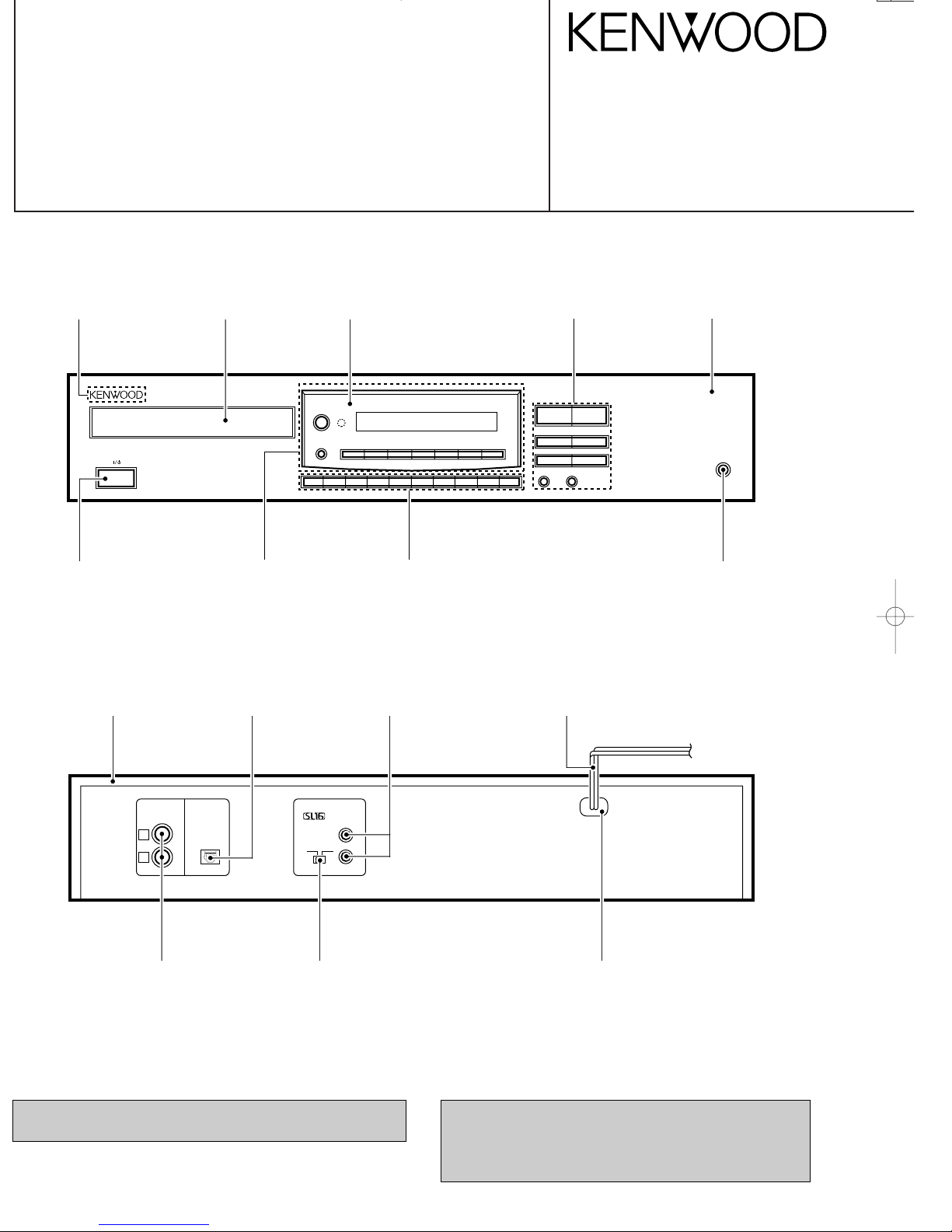
1
-ON –STANDBY
P.MODE CHECK CLEAR EDIT
TIME
DISPLAY
REPEAT
PEAK
SEARCH
234567890
DISPLAY
76
¢4
¡1
STOP PLAY/PAUSE
+10 RANDOM
PHONES
0
Knob
(k29-6469-08)
Phone jack
(E11-0339-08)
L
R
OUTPUT
DIGITAL
OUTPUT
SYSTEM CONTROL
SL16 XS 8
ƒ
OPTICAL
KENWOOD badge
(B43-0302-04)
Front glass
(B10-2403-08)
Dressing panel
(A21-3603-08)
Knob
(k29-6815-08)
Metallic cabinet
(A01-3356-08)
Power cord bushing
(J42-0200-08)
Phono jack
(E63-0188-08)
Slide switch
(S62-0069-08)
AC power cord *
(E30-)
Miniature phone jack
(E11-0333-08)
Optic receving module
(W02-2620-08)
Knob
(K29-6471-08)
Escutcheon
(B07-2388-08)
Panel *
(A60-)
Illust is DP-3080MkΙΙ.
* Refer to parts list on page 14.
CONTENTS / ACCESSORIES / CAUTIONS
DISASSEMBLY FOR REPAIR
Beware of condensation
When water vapor comes into contact with the surface of cold
material, water drops are produced.
If condensation occurs, correct operation may not be possible, or
the unit may not function correctly.
This is not a malfunction, however, the unit should be dried.
To do this, turn the ON/STANDBY switch ON and leave the unit
as it is for several hours.
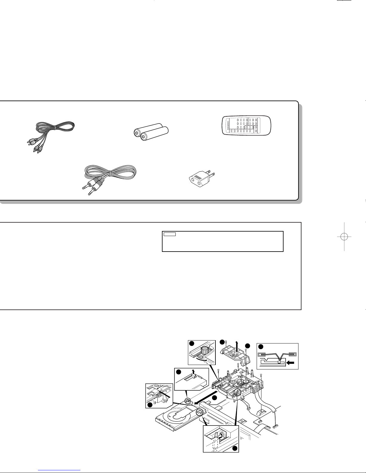
Audio cord...........................................(1)
(E30-2841-08)
AC plug adaptor.................................(1)
(E40-9981-08) M type only
Remote control unit ..........................(1)
(A70-1181-08) : RC-P03050
Battery cover (A09-0356-08)
Batteries (R6/AA)................................(2)
SCHEMATIC DIAGRAM............................................ 7
EXPLODED VIEW .................................................. 12
PARTS LIST..............................................................14
SPECIFICATIONS....................................................17
REMOTE CONTROL UNIT
RC-P0505
System control cord..........................(1)
(E30-2629-05)
1 2 3 4 5
6 7 8 9 10
11 12 13 14 15
16 17 18 19 20
TRACK
no d sc
1
Be especially careful in the following conditions:
¶ When the unit is brought from a cold place to a warm place, and
there is a large temperature difference.
¶ When a heater starts operating.
¶ When the unit is brought from an air-conditioned place to a place
of high temperature with high humidity.
¶ When there is a large difference between the internal temperature
of the unit and the ambient temperature, or in conditions where
condensation occurs easily.
Note related to transportation and movement
Before transporting or moving this unit, carry out the following
operations.
1. Turn the power ON but do not load a disc.
2. Verify that the display shown appears.
3. Wait a few seconds and set the unit to STANDBY mode.
1), then remove the clamper
fram.
on the position A (3).
the leaf switch in the left direction (5).
pull out the tray (7).
1
1
2
3
6
4
7
CP401
CP201
5
position
"A"

DP-3080MkΙΙ/3090
3
CIRCUIT DESCRIPTION
Pin No. Pin name I/O Description
1 GFS I NOT USED
2 RMC I REMOCON INPUT PRT
3-5 – I NOT USED
6 MUTE O DIGITAL MUTE (ON: "H")
7 MLEN O TC9423F LATCH CONTROL
8 MCK O TC9423F CLOCK CONTROL
9 SENS I SENSE INPUT FROM CXD2507
10 MDT O TC9423F DATA CONTROL
11 SQCK O CLOCK TO READ Q_DATA
12 SUBQ I Q_DATA INPUT PORT
13 – O NOT USED
14-17 KR0-KR3 I KEY INPUT PORT
18 OPEN_M O OPEN MOTOR (ACTIVE "L")
19 CLOSE_M O CLOSE MOTOR (ACTIVE "L")
20 MON O SPINDLE MOTOR ON "H"
21 – O NOT USED
22 DATA O DATA OUT TO CXD2507
23 XLT O LATCH OUT TO CXD2507
24 CLK O CLOCK OUT TO CXD2507
25 FOK I FOCUS OK INPUT PORT
26 LDON O LASER OUTPUT (ON: "L")
27 A_MUTE O ANALOGUE MUTE (ON: "H")
28 XRST O IC RESET PORT
29 AD_IN I A/D CONVERT INPUT PORT
30 RESET – (RESET)
31 XI – (XTAL1)
32 XO – (XTAL0)
33 Vss – (GND)
34-46 – O NOT USED
47-57 S11-S1 O FL SEGMENT PORT
58-61 – O NOT USED
62-70 G9-G1 O FL DIGIT PORT
71 Vfdp – FL DRIVER POWER (-26V)
72 Vdd – (+5V)
73 NC – CONNECTED TO Vdd
74 FED_SW I LIMIT SWITCH (ON: "L")
75 MODE_SW I 8/16BIT (L: 8BIT , H: 16BIT)
76 S_DATA I/O SYSTEM SERIAL DATA
77 S_BUSY I/O SYSTEM SERIAL BUSY
78 SCCR I SCOR FROM CXD2507
79 OP_SW I OPEN SWITCH (ON: "L")
80 CL_SW I CLOSE SWITCH (ON: "L")
1. Microprocessor ; (MAIN unit ; IC601)
1-1 Pin description
ADJUSTMENT
No.
1
2
3
FOCUS
OFFSET
TRACKING
BALANCE
TRACKING
GAIN
TEST DISC
TYPE 4
Test disc
type4 Apply
signal of
1.2kHz
50mVrms to
TP301 pin5-6.
TEST DISC
TYPE 4
CONNECT AN
OSCILLOSCOPE
to TP301
CH1 : RF(
1)
CONNECT AN
OSCILLOSCOPE
to TP301
CH1 : TE1(5)
CH2 : VC(4)
Connect a LPF to
TP301 pin 5-6 to
which you connect
an oscilloscope or
AC voltmeters.
STOP
PLAY
SHORT–CIRCUIT
TP2 WITH TP5
AFTER THE
ADJUSTMENT
REMOVE
SHORT–WIRE
PLAY
VR301
FE OFFSET
VR302
TE BALANCE
VR303
TE GAIN
DC=0V
SYMMETRY
BETWEEN
UPPER AND
LOWER
Two VTVMs
should read the
some value.
(e)
ITEM
INPUT
SETTING
OUTPUT
SETTING
PLAYER
SETTING
ALIGNMENT
POINT
ALIGN FOR FIG.
1. WITH PRESSING PLAY/PAUSE ( 66) TURN THE POWER ON TO ENTER THE TEST MODE.
2. SET THE TEST DISC TO DISC NO SONY YEDS–18. (TYPE4)
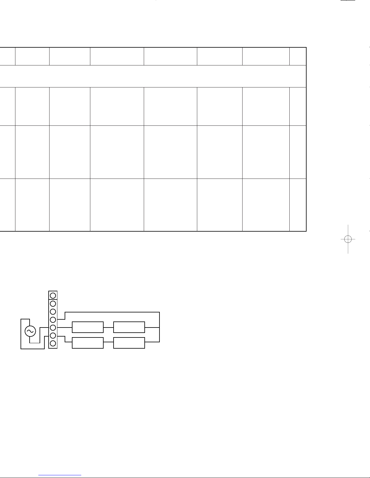
GND
TP301
+
_
L.P.F.
+
+
L.P.F.
VTVM
VTVM
1
2
3
4
5
6
7
ACEGIBDFHJ
2
1
3
5
7
4
6
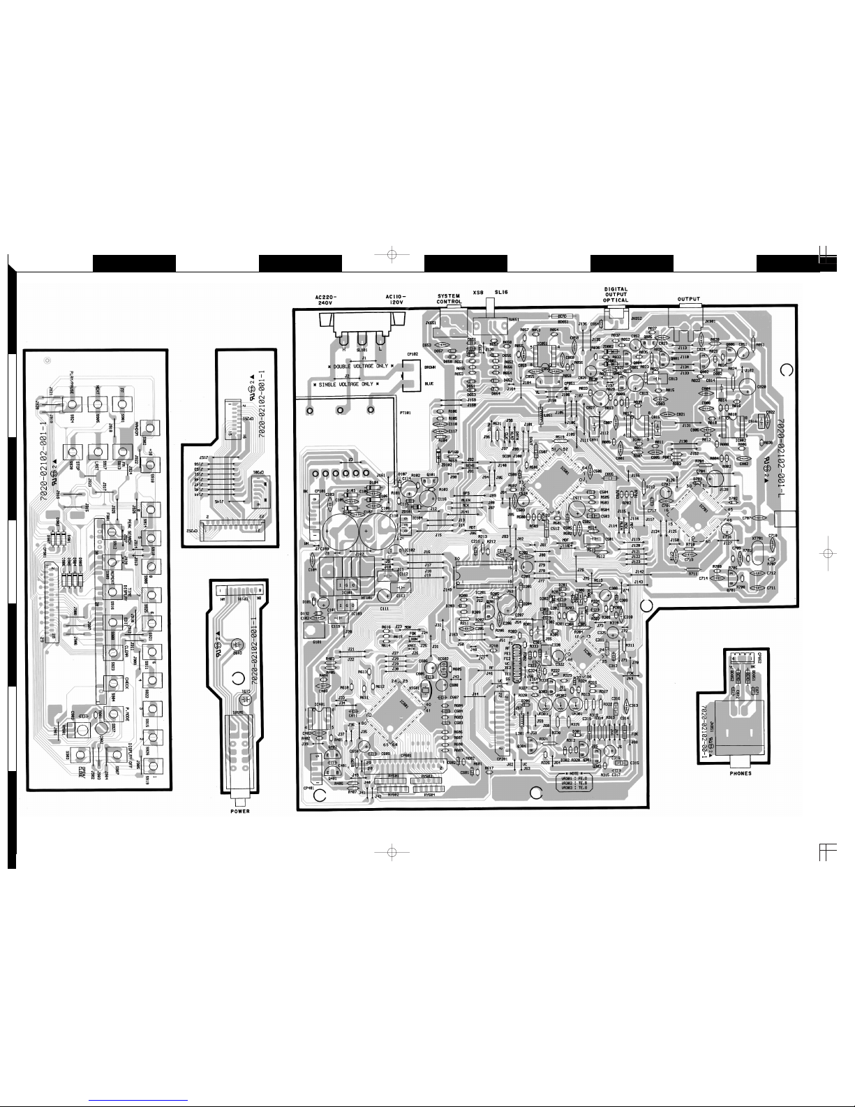
Refer to the schematic diagram for the value of resistors and capacitors.
PC BOARD(Component side view)
5 6
 Loading...