

Kenwood CT-201/KXF-W1010 Service Manual

STEREO DOUBLE CASSETTE DECK
CT-201/KXF-W1010
7
Q
Q
Lid glass
(B03-3833-08)
TEL 13942296513 QQ 376315150 892498299
TEL
Knob (PLAY)
(K27-2217-08)
3
SERVICE MANUAL
KENWOOD badge
(B43-0302-04)
Knob (REW)
(K27-2218-08)
13942296513
6
Knob (F.F)
(K27-2219-08)
1
3
Cassette lid (L) *
(A53-)
Knob (STOP/EJECT)
(K27-2220-08)
5
Knob (PAUSE)
(K27-2221-08)
1
5
Front window
(B03-3834-08)
Knob (POWER) *
(K27-)
0
Display cover
(B03-3807-08)
3
Q
Q
Knob (FUNCTION) *
(K27-)
Knob (REC LEVEL) *
(K27-)
7
8
Panel *
(A60-)
6
9
Knob (REC)
(K27-2222-08)
1
3
4
2
© 1998-04/B51-5423-00 (K/K) 3162
Knob (REW)
(K27-2218-08)
8
0
5
1
5
Knob (PLAY)
(K27-2223-08)
8
9
Cassette lid (R) *
(A53-)
Knob (STOP/EJECT)
(K27-2220-08)
9
4
2
9
Knob (F.F)
(K27-2219-08)
2
9
Lid glass
(B03-3833-08)
2
8
Knob (PAUSE)
(K27-2221-08)
9
9
TEL 13942296513 QQ 376315150 892498299
9
w
w
Metallic cabinet
(A01-3451-08)
Phono jack (REC, PLAY)
(E11-0264-08)
w
.
xia
o
y
u
AC outlet *
(E03-0351-08)
1
6
3
AC power cord bushing
(J42-0083-05)
AC power cord *
(E30-)
.
c
o
m
* Refer to parts list on page 12.
CT-201/KXF-W1010
CONTENTS/ACCESSORIES/CAUTION
Contents
Q
Q
CONTENTS/ACCESSORIES/CAUTION....................2
ADJUSTMENT............................................................3
PC BOARD .................................................................5
SCHEMATIC DIAGRAM.............................................7
* Please refer to KX-W594/W1060 Service Manual (B51-4924-00) if you want to know disassembly and
mechanism operation.
TEL 13942296513 QQ 376315150 892498299
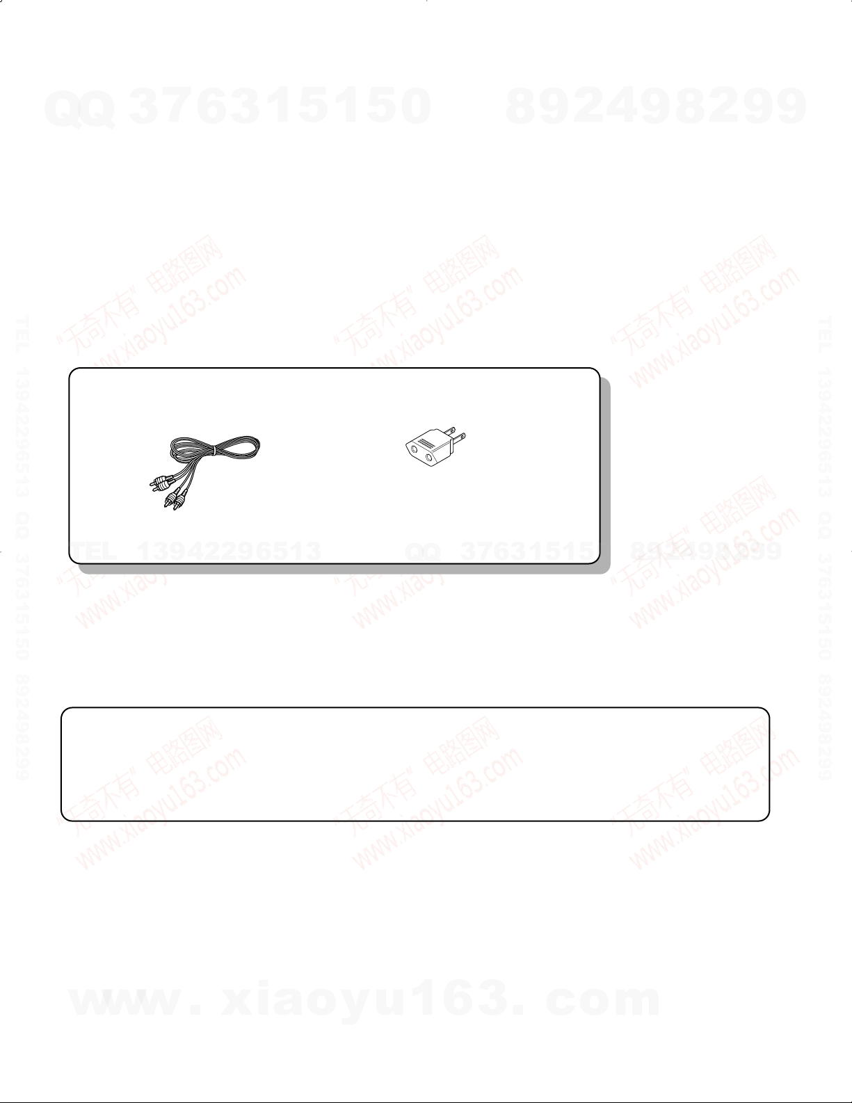
Accessories
TEL
7
3
Audio cord ..............................2
(E30-0615-05)
13942296513
6
3
1
5
1
5
0
EXPLODED VIEW ......................................................9
PARTS LIST..............................................................12
PARTS DESCRIPTIONS..........................................15
SPECIFICATIONS.. ....................................Back cover
AC plug adaptor.......................1
(E03-0115-05)
(Except for Europe and Australia)
For the unit with a European AC plug in
areas other than Europe
7
3
Q
Q
6
8
3
9
1
5
1
2
5
4
0
9
8
9
8
2
4
2
9
8
9
2
9
9
TEL 13942296513 QQ 376315150 892498299
9
Caution
Beware of condensation
When water vapor comes into contact with the surface of cold
material, water drops are produced. If condensation occurs, correct
operation may not be possible, or the unit may not function correctly. This is not a malfunction, however, and the unit should be dried.
(To do this , turn the POWER switch ON and leave the unit for several hours.)
w
w
w
2
.
xia
o
y
u
Be especially careful in the following conditions:
* When the unit is brought from a cold place to a warm place,
and there is a large temperature difference.
* When a heater starts operating.
* When the unit is brought from an air-conditioned place to a
place of high temperature with high humidity
* When there is a large difference between the internal tempera-
ture of the unit and the ambient temperature, or in conditions
where condensation occurs easily
1
6
3
.
c
o
m

No.
ITEM
INPUT
SETTINGS
OUTPUT
SETTINGS
CASSETTE DECK
SETTINGS
ALIGNMENT
POINT
ALIGN FOR
FLG.
CASSETTE DECK SECTION
TAPE: NORMAL, DOLBY: OFF, INPUT: LINE IN
0 dBs = 0.775 V
I. REC/PLAY HEAD
[ 1 ]
DEMAGNET-
IZATION
–
–
POWER OFF
Remove the cassette door.
REC/PLAY
head
Demagnetize the REC/PLAY
head with a head
demagnetizer.
[ 2 ]
CLEANING
––PLAY
REC/PLAY
head, erase
head, capstan
pinch roller
Clean the REC/PLAY head,
erase head, capstan and pinch
roller using a cotton swab
slightly damped with alcohol.
[ 3 ]
AZIMUTH
(A)
MTT·114, TCC-153
0 kHz, -10 dB
(B)
PLAY
Azimuth
adjustment
screw
Maximum output.
(a)
II. DC BOARD
[ 1 ]
TAPE SPEED
(A)
MTT-111, TCC-110
3 kHz
(B)
PLAY
Timming
potentiometer in
the DC motor.
Adjust the tape speed so that a
3 kHz signal is produced at the
center of the tape.
(b)
III. PC BOARD
< 1 >
PLAYBACK
LEVEL
MTT-150
400 Hz (200 nWb)
(B)
PLAY
DECK A
SFR101 (L)
SFR102 (R)
Output level : -1 dBs
MTT-256
315 Hz (160 nWb)
Output level : -4 dBs
DECK B
SFR103 (L)
SFR104 (R)
MTT-256U, TCC-160
315 Hz ( 250 nWb)
Output level : 0 dBs
< 2 >
LED LEVEL
MTT-256U, TCC-160
315 Hz ( 250 nWb)
(B)
PLAY
SFR109 (L)
Adjust the variable resistros
so that LED level of 0 dBs is
worked.
< 3 >
BIAS
CURRENT
(A)
1 kHz, -20 dBs
10 kHz, -20 dBs
(B)
Adjust REC level VR so that
the REC monitor output
becomes -20 dBs at 1 kHz,
then record and reproduce
signal of 1 kHz and 10 kHz in
alternation.
SFR107 (L)
SFR108 (R)
Record 1 kHz and 10 kHz in
alternation and adjust the
variable resistors which
control the bias current so that
the same playback level is
obtained.
< 4 >
RECORD
LEVEL
(A)
1 kHz, -20 dBs
(B)
Record and reproduce a
1 kHz, signal under the
conditions set in < 3 >.
SFR105 (L)
SFR106 (R)
Adjust the variable resistors
so that LED level of 20 dBs is
worked.
CT-201/KXF-W1010
ADJUSTMENT
7
Q
Q
TEL 13942296513 QQ 376315150 892498299
3
6
3
1
5
1
5
0
8
9
2
4
9
8
2
9
9
TEL 13942296513 QQ 376315150 892498299
TEL
13942296513
Q
Q
3
7
6
3
1
5
1
5
0
8
9
2
4
9
8
2
9
9
w
w
w
.
xia
o
y
u
1
6
3
.
c
o
m
3

(A)
(B)
AC voltmeter AG
Oscilloscope
AC voltmeter
Frequency counter
L
R
REC PLAY
CT-201/KXF-W1010
ADJUSTMENT
7
Q
Q
TEL 13942296513 QQ 376315150 892498299
3
6
3
1
5
1
5
0
8
9
2
4
9
8
2
9
9
TEL 13942296513 QQ 376315150 892498299
TEL
13942296513
Q
Q
6
7
3
3
1
0
5
1
5
8
9
2
4
9
8
2
9
9
4
w
w
w
.
xia
o
y
u
1
6
3
.
c
o
m
ACEGIBDFHJ
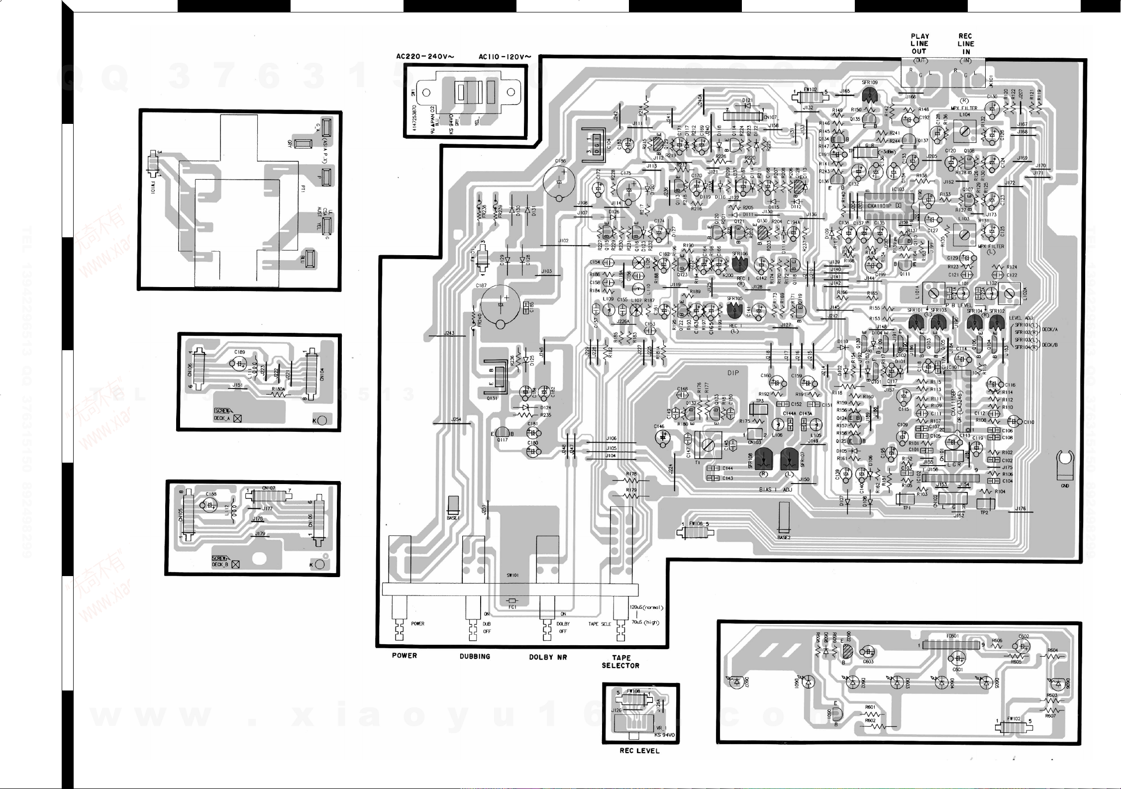
PC BOARD(Component side view)
1
Q
2
TEL 13942296513 QQ 376315150 892498299
3
Q
3
7
6
3
1
5
1
5
0
8
9
2
4
9
8
2
9
9
TEL 13942296513 QQ 376315150 892498299
T
E
4
5
6
L
1
3
9
4
2
2
9
6
5
1
3
Q
Q
3
7
6
3
1
5
1
5
0
8
9
2
4
9
8
2
9
9
w
7
Refer to the schematic diagram for the value of resistors and capacitors.
w
w
.
x
i
a
o
y
u
1
6
5 6
3
.
c
o
m
 Loading...