

Page 1
EQplus
AUDIO
PROCESSOR
OPERATING MANUAL
Page 2
EQplus
AUDIO
PROCESSOR
OPERATING MANUAL
September 2004
W2IHY
TECHNOLOGIES
Julius D. Jones
19 Vanessa Lane
Staatsburg, N.Y. (12580)
(845) 889-4253
E-mail: Julius@W2IHY.COM
Home Page: http:// www.w2ihy.com
c 2004 W2IHY, ALL RIGHTS RESERVED
-2-
Page 3

TABLE OF CONTENTS
Introduction ......................... 4
Front Panel Controls .......... 5 - 9
Rear Panel Controls ............10 - 11
Schematic (Front Panel) .......12 - 13
Schematic (Rear Panel) .......14
Rear Panel Controls ...........15
Getting Started Tutorial .......16-19
Internal Wiring .................... 20
Audio Out Cable wiring ...... 21 - 24
-3-
Page 4

INTRODUCTION
EQplus
AUDIO
PROCESSOR
The EQplus is the next generation of audio processing
equipment from W2IHY Technologies. The EQplus was
designed to be directly attached to the world famous
W2IHY 8 Band EQ. The EQplus provides features such
as Audio Compression, Downward Expansion, Effects
and connectivity to 3 radios. All these features, and
more, were designed in a way that makes the EQplus
easy to use. Extensive testing was done by amateurs
on many different radios on AM, FM and SSB so that the
product would be ready for you to use problem free.
Buying the EQplus gives you the availability to Amateur
Service unrivaled in the hobby. We feel so confident that
you will be delighted with the EQplus that we offer a 30
day money back, no questions asked guarantee. The
EQplus represents the new reference point for easy to
use amateur radio audio equipment.
If I did not think you would be delighted with The EQplus
I would have not put my call sign on it. Thanks for your
purchase and we appreciate your business.
Julius D, Jones (W2IHY)
-4-
Page 5
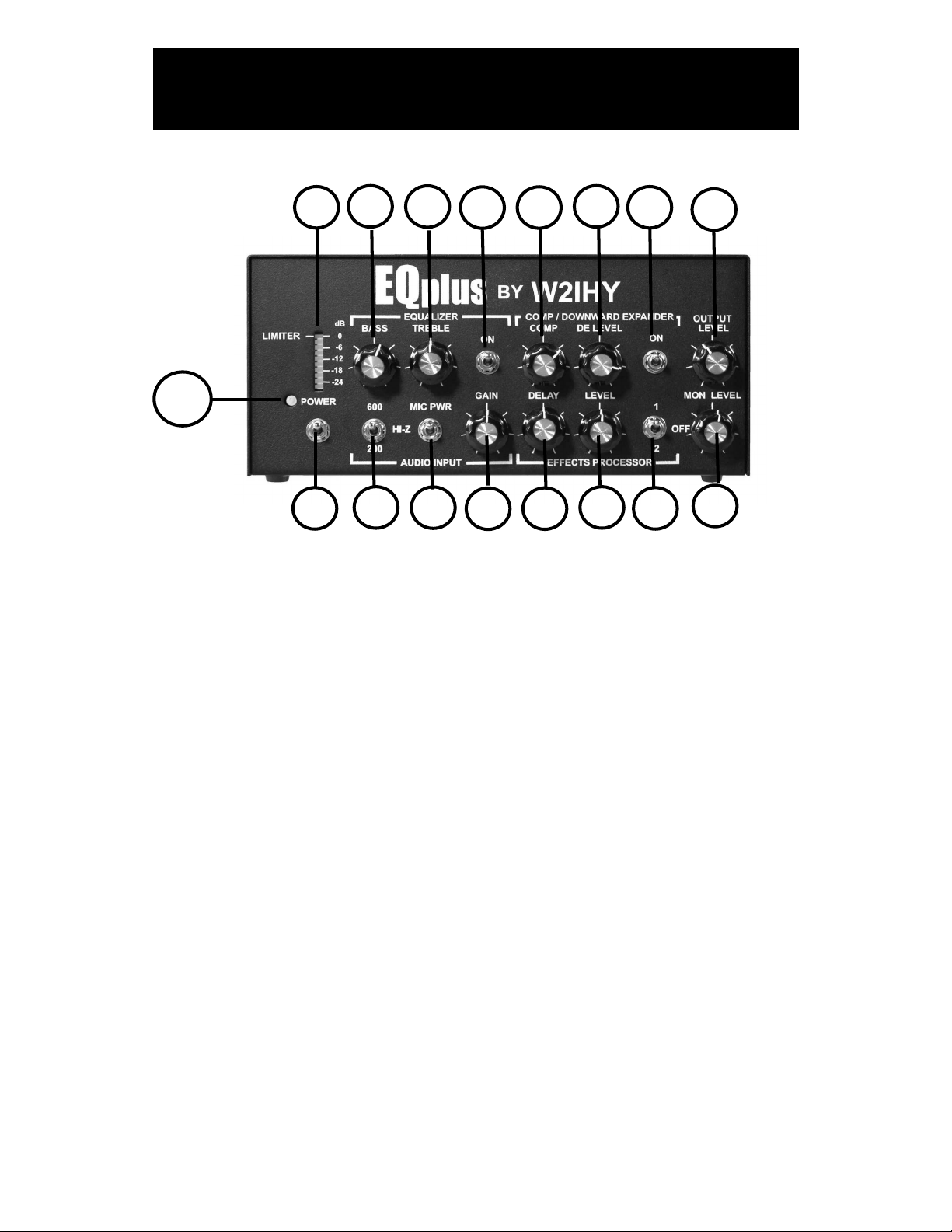
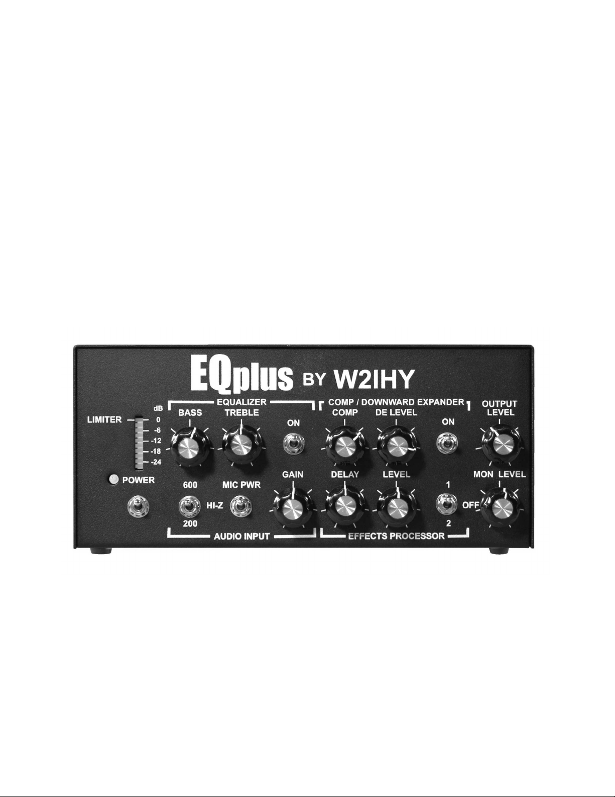
FRONT PANEL CONTROLS
6
8
9
7
11
12
10
16
2
1
This section describes each of the controls on the front panel. You
should read through this section now. Some of the descriptions will
be more meaningful after you first work through the Getting
Started Tutorial.
4
3
5
14
15
13
17
(1) Power On/Off Switch (S1)
This switch turns the unit's power on and off.
(2) Power on LED (LED1)
This LED goes on when power is on in the unit.
(3) Audio Input Mic PWR (Power) Switch (S6)
Turning this switch on puts +5V onto what is plugged into the Mic
In and Aux Input connectors. The Mic power switch must be on if
you have any of the following microphones connected directly into
the EQplus:
- ICOM HM12, HM36, SM6 etc..
- Heil microphones made specifically for ICOM radio’s such as
the HMI and ICM
- Elecract MH2 (made for the Elecraft radio by Heil Sound )
-5-
Page 6
FRONT PANEL CONTROLS
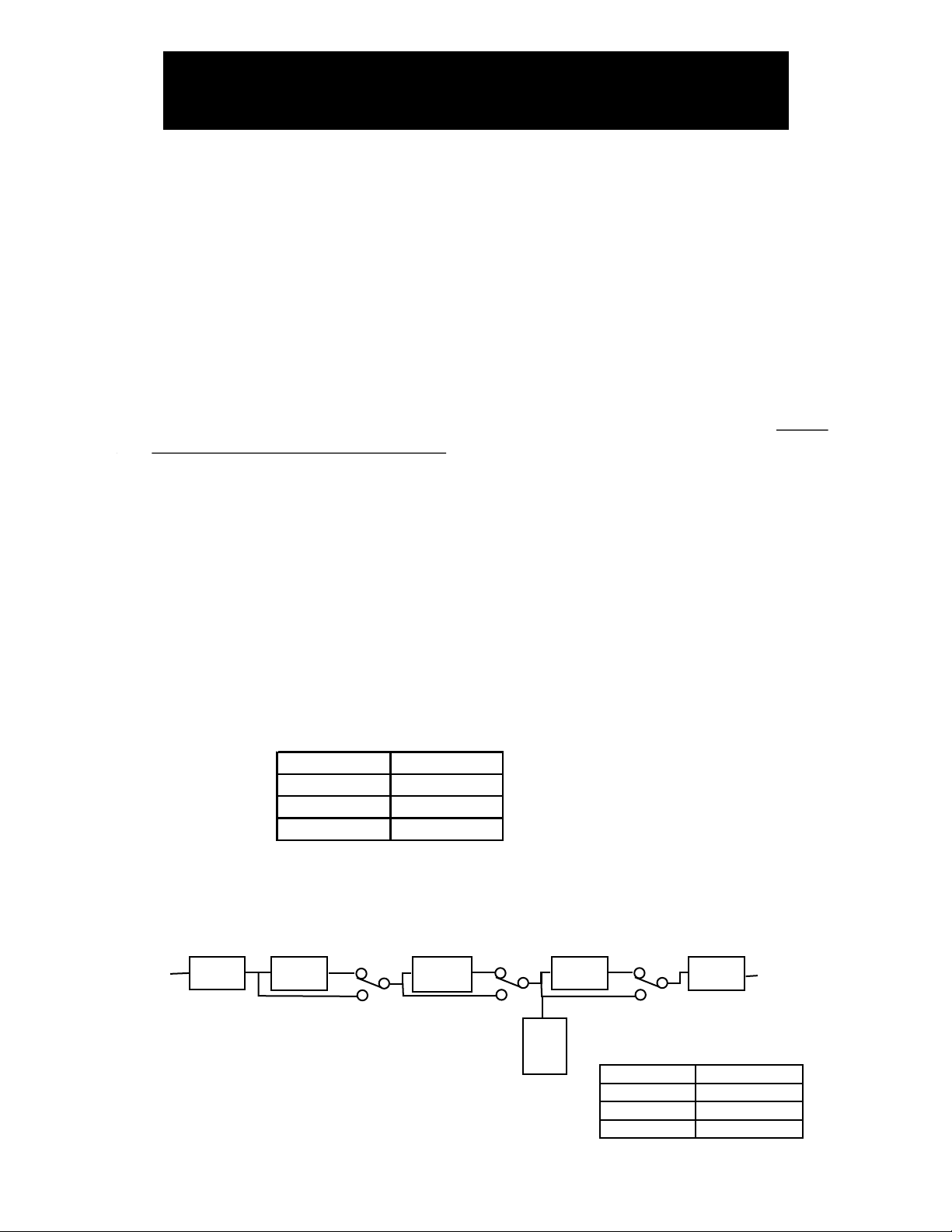
EQplus BAR GRAPH MONITORING
Compressor Equalizer
Bar graph monitoring
off off Output of Audio Amp
off on Output of Equlaizer
on off Output of Compressor
on on Output of Compressor
dB reading
Peak to Peak
voltage
0 1 Volt
-6 500 mv
-12 250 mv
-24 125 mv
(4) Audio Input Impedance Switch (S5)
This 3 position toggle switch is used to change the input impedance
of the Mic and Aux Inputs (19,20 & 21). Input Impedances of 200 ohms,
600 ohms and 50K ohms ( HI-Z)may be selected.
(5) Mic In Gain (R12)
This potentiometer, when turned clockwise, can increase the Audio Input
signal levels up to about +40dBv. The mic gain should be changed while
speaking into the microphone, until 3 or 4 green Bar Graph (7) LED’s
are illuminated. Audio levels should be maintained in the green and
yellow ranges of the LED Bar Graph(6) .
(6) LED Bar Graph
The 10 segment LED Bar Graph indicates peak to peak EQplus internal
audio levels. The position of the Equalizer (7) and Compressor /
Downward Expander (10) switches control what internal function is being
indicated. The tables below defines what the LED Bar Graph is indicating.
The pictorial below shows the EQplus Audio Chain
EQplus AUDIO CHAIN
ON
VV
OFF
VV
AUDIO
AMP
VV
Audio Out
Audio IN
Audio
VV
Amp
VV
Band EQ
Dual
ON
VV
OFF
Comp./
Dwrd Expd.
VV
ON
VV
OFF
VV
BAR
GRAPH
EFFECTS
PROC.
-6-
Page 7

FRONT PANEL CONTROLS
(7) Equalizer On/Off Switch (S3)
This switch turns the Equalizer on and off. When the equalizer is
off, adjusting the bass and treble controls have no effect on the
output audio.
(8) Equalizer Bass (R37)
This rotary potentiometer works only when the Equalizer Switch
(7) is on. Turning this control clockwise increases the amount of
bass boost. Turning this control counterclockwise decreases the
amount of bass boost. The detent at the half way point of rotation
represents 0 dB of boost. Each case marking represents 4dB.
(9) Equalizer Treble (R38)
This rotary potentiometer works only when the Equalizer Switch
(7) is on. Turning the control clockwise increases the amount of
treble boost. Turning this control counterclockwise decreases the
amount of treble boost. The detent at the half way point of rotation
represents 0 dB of boost. Each case marking represents 4dB.
(10) Compressor / Downward Expander On/Off Switch (S2)
When the switch is in the off position the compressor and
downward expander have no effect on the EQplus’s audio.
(11) Compressor / Downward Expander COMPRESSOR (COMP)
POTENTIOMETER (R22)
This potentiometer works only if the Compressor / Downward
Expander switch (10) is on. The COMP potentiometer controls
the amount of compression that will be done by the unit. If the
COMP potentiometer is turned fully counterclockwise then there
will be no compression introduced (0 dB) to incoming signals.
If the COMP potentiometer is rotated fully clockwise then
-7-
Page 8

FRONT PANEL CONTROLS
Incoming signals will have up to 20dB of compression introduced.
The EQplus compressor circuitry contains a limiter that is preset
at the factory. The limiter is set to limit the processed signals to
375 millivolts (-9 dB). When this level is reached the 1-st yellow
LED on the bar graph will be on and the top Red (Limiting) LED
will turn on. Additional increases in audio level, using either the
Audio Input Gain Potentiometer or the Equalizer Potentiometers,
will result in a small increase in output from the compressor’s
circuitry. The good news is that the EQplus can produce high
levels of compression while maintaining fidelity and very low
distortion levels. The RF compressors in many radio’s have
difficulty attaining high levels of compression with low levels
of distortions. RF compressors roll off the low end audio response
of the signals they process. The net result of the EQplus
compressor is up to 20dB of signal compression with very low
distortion and little to no change in overall audio bandwidth. .
(12) Compressor / Downward Expander Downward Expander
Level (DE LEVEL) POTENTIOMETER (R47)
This potentiometer works only if the Compressor / Downward
Expander switch (10) is on. The Downward Expander removes
unwanted audible sounds such as fan noise. The Downward
Expander is operated by turning the DE LEVEL Control clockwise
just to the point where unwanted sounds are removed.
(13) EFFECTS PROCESSOR PROGRAM SELECT / OFF
SWITCH (S4)
This 3 position toggle switch is used to select one of two effects or
to turn the Effects Processor off. When the Effects Processor is
off the Effects Processor Delay and Level controls will not modify
internal EQplus audio. The toggle switch in position 1 selects
Effect 1. Effect 1 emulates dampening sound reflecting multiple
times from a surface. The toggle switch in the position 2 selects
Effect 2. Effect 2 emulates sound reflecting once from a surface.
-8-
Page 9

FRONT PANEL CONTROLS
(14) EFFECTS PROCESSOR DELAY Potentiometer (R42)
This potentiometer works only if the Effects Processor 3 position
toggle switch is selecting either effect 1 or effect 2. The Delay
control, when rotated clockwise increases, by up to about
80 milliseconds, the time that audio waveform is delayed. The
delayed waveform is then mixed with the original non delayed
waveform. The mixed waveform is next sent to the output of
the EQplus.
When the pot is turned clockwise, at the halfway point, there is a
detent. This represents a starting point for adjusting the Effects
Processor Delay..
(15) EFFECTS PROCESSOR LEVEL Potentiometer (R47)
This potentiometer works only if the Effects Processor 3 position
toggle switch is selecting either effect 1 or effect 2. The Level
control, when rotated clockwise, increases the amplitude that
the delayed audio waveform is combined with the original non
delayed waveform.
When the pot is turned clockwise, at the halfway point, there is a
detent. This represents a starting point for adjusting the Effects
Processor Level.
(16) OUTPUT LEVEL Potentiometer (R44)
This potentiometer varies the output level from about 10
millivolts to about 1 volt peak to peak.
(17) Monitor (Mon) LEVEL Potentiometer (R39)
This potentiometer adjusts the audio level into the Phones
Connector (24).
-9-
Page 10

REAR PANEL CONTROLS
25
24
18
22
20
22
23
21
19
(18) MIC SELECT
This three position switch selects the YAESU, KENWOOD or
ICOM microphone plugged into the 8 pin Mic Input (19).
(Other microphones supported with mic adapters)
(19) MIC INPUT
This Input uses an 8 Pin microphone male connector. The
impedance of this input is set by the Audio Input 3 position
toggle switch (4). Do not use this connector when RCA Mic
In (20) or the Aux Input (21) is being used.
J8
Pin
1
2
5
6
7
Icom Ken Yaesu
+Mic +Mic
+5V PTT +5V
PTT +5V
PTT
PTT
Gnd
PTT
Gnd
Gnd - Mic Gnd
Gnd +Mic
8
-10-
Page 11

REAR PANEL CONTROLS
(20) MIC INPUT
This RCA female connector is used as a microphone
input. This connector works independent of the Mic Select
switch (18) and may be used for another audio input
source such as a microphone. The impedance of this
input is set by the Audio Input 3 position toggle switch (4).
(21) AUX INPUT
This 5 Pin Din connector allows audio to be brought into
the EQplus from an external device..This connector
works independent of the Mic Select switch (18) and may
be used for another audio input source such as a
W2IHY 8 Band EQ. The impedance of this input is set by
the Audio Input 3 position toggle switch (4).
+ Audio IN
AUX INPUT
- AUDIO IN
5 Pin Male DIN
Din connectors shown
PTT
on side to be soldered
Gnd
(22) PTT INPUT
This female RCA connector is for push to talk control. A foot
switch or other device may be connected. Grounding the
center of the connector grounds the push to talk line on the
selected Audio Output.
(22) OUTPUT SELECT
This three position rotary switch directs audio to one of 3
5 Pin DIN connectors (Output1, Output 2 or Output 3.)
-11-
Page 12

REAR PANEL CONTROLS
(23) AUDIO OUTPUTS 1,2 and 3
The audio output and PTT outputs of the EQplus uses these
5 pin DIN’s. When the Audio Output Rotary switch (22) is in
the “1” position, audio is active at Audio Output 1. When the
Audio Output Rotary switch (22) is in the “2” position, audio
is active at Audio Output 2. When the Audio Output Rotary
Switch (22) is in the “3” position, audio is active at Audio
Output 3. The diagram below shows the configuration of each
of the 3 outputs.
AUDIO OUT 1/2/3
5 Pin Male DIN
Din connectors shown
+ Audio
- Audio
Hi-Z Output
PTT
Balanced
Output
on side to be soldered
Gnd
(24) PHONES
This 1/4“ Stereo headphone connector can be used to monitor
audio from the EQplus. The output level of this connector is
controlled by the Monitor Level control(1). Important: Unless
headphones using 1/4” stereo connectors are used, the
EQplus monitor will not operate properly.
(An inline adapter should be used with headsets that do not
use 1/4“ stereo connectors. Stores like Radio Shack have
such adapters available.)
(25) Power
5 Pin Din connector. 7 - 14 VDC input at 100 ma.
Power
5 Pin Male DIN
Din connectors shown
GND
on side to be soldered
+7 to 14V
-15-
Page 13

GETTING STARTED TUTORIAL
Before plugging the power transformer into the wall, preset the
EQplus controls as indicated:
Power , Equalizer, Compressor/ Downward and Effects
Processor all off.
connector. T
be using. If you are not using a mic but an external audio source
like a W2IHY EQ, connect your audio source into the Aux Input. (If
you are using a W2IHY EQ, then connect a cable between the Mic
Out of the EQ and the Aux Input of the EQplus.)
Plug the power transformer (power cube) into the wall and into the
Power connector of the EQplus. Attach the audio cable between
your transceiver/transmitter and the Audio Out of the EQplus.
If you are using a mic into the EQ plus and you are using
an electret mic such as an ICOM Hm12, Hm36, Sm6,... or a
Heil Mic made for ICOM radios, then turn the front panel Audio
Input Mic Pwr switch on. Set the Audio Input impedance (4) for
the impedance of the mic that is connected into the MIC IN. Most
amateur radio mics are 600 ohms.
If you are using a W2IHY 8 Band EQ or other audio device
into the EQ plus make, sure the front panel Audio Input Mic PWR
urn the Mic Select to select the microphone you will
Connect your microphone into the Mic In rear
Switch (3) is off. Set the Audio Input impedance ( 4) to 600 ohms.
Adjusting the Audio Input Level using a Mic into the EQplus
Turn on the power on the 8 band EQ and the EQ plus.
Connect a mic into the EQplus 8 pin MIC IN Connector (19).
Turn the rear mounted Mic Select switch (18) to the correct
manufacturer the mic is wired for (Yaesu/Kenwood/ICOM).
While talking into your mic, adjust the Audio Input Gain (5)
so that 2 or 3 Green LED’s on the bar graph light up.
Adjusting the Audio Input Level using a
W2IHY 8 Band EQ into the EQplus
Turn on the power on the 8 band EQ and the EQ plus. Connect
a mic into the 8 Band EQ. While talking into your mic, adjust the
-16-
Page 14

GETTING STARTED TUTORIAL
Audio Input Gain (5) so that 2 or 3 Green Bar Graph LED’s
light up. This may require adjusting both the Mic Gain control
on the 8 Band EQ and the Audio Gain control on the EQplus.
Using The EQplus headphone (PHONES) Monitor
Connect a set of stereo headsets into the 1/4 inch “Phones”
Connector located in the back of the EQplus. Talk into the mic
to hear audio coming from the EQplus. Adjust the headset
volume by turning the front panel Monitor Level control (17)
Adjusting an External Equalizer connected to the EQplus
If you are using an external audio device, such as a W2IHY
8 Band EQ, use the same equalizer settings you were using prior
to using the EQplus.
Adjusting the EQPlus Dual Band EQ
Turn the Equalizer Switch (7) on. Turning the Treble
potentiometer (9) clockwise up will increase the amount of high
frequencies present in the Audio Out (23) The detent midway
through the rotation is 0dB gain point. Turning the Bass
potentiometer (8) clockwise will increase the amount of low
frequencies present in the Audio Out (23) The detent midway
through the rotation is the 0dB gain point. Experimentation will
be required to determine the optimal settings for the Equalizer.
USING THE COMPRESSOR/ DOWNWARD EXPANDER
- With the Compressor/ Downward Expander off, the audio
level, as seen on the LED Bar Graph, should be adjusted so
that 2 or 3 green LED’s are on. This level may be adjusted
using the Audio Input Gain control (5).
- Turn the Compressor / Downward Expander on (10). Turn the
DE (Downward Expander ) control (12) fully counter
clockwise. This will effectively turn the Downward Expander off.
..
-17-
Page 15

GETTING STARTED TUTORIAL
- Turn the Compressor control (11) fully counter clockwise.
This setting passes uncompressed audio thru the
compressor. Turning the compressor control clockwise
increase the amount of compression. Set the compression to
the desired level. You can turn the compression levels
up to a point where talking into the mic causes the RED
Limiting LED to come on . The Red LED coming on indicates
that additional increases in audio signal levels, into the
compressor, will result in minimal signal level increase at the
output of the compressor. Limiting of audio signal levels occur
when the Compressor is on and the internal audio signals
exceed -9db (first yellow LED on). The EQplus creates no
perceptible distortion to audio that is heavily compressed.
- The Downward Expander (12) can be used to reduce
background noise. The EQplus monitor may be used to assist
in adjustment of the Downward Expander. Connect your
stereo headsets into the rear panel 1/4” stereo Phones
connector (24). Listen to audio from the EQplus while talking
into the mic. Adjust the front panel Monitor Level control (1)
to a comfortable listening level. When you are not talking,
listen in the headsets for background noise. Turn the DE
LEVEL (Downward Expansion) control (12) clockwise. You
should hear the background noise level reduce as you turn this
control clockwise. As you continue to turn the control knob
clockwise there will be a point where the background noise will
disappear. At the point where the background noise disappears
talk into your mic to make sure you have not turned the
Downward Expander control too far. Turning the control too far
will result in choppy and or distorted audio. If the monitored
audio is choppy or distorted then turn the Downward
Expander knob counterclockwise until the audio heard is clear.
ADJUSTING THE EFFECTS
The EFFECTS PROCESSOR adjusts audio to add resonance
and ambiance. The Delay control (14) sets the time that audio
is delayed before it is mixed back into the non delayed audio.
-18-
Page 16

GETTING STARTED TUTORIAL
The Level control (15) sets the amplitude that the audio delayed
by the Effects Processor combines with the non delayed audio.
Through experimentation, the user can find what Effects
Processor Delay and Level settings are best for their voice
characteristics. Both the Delay and Level controls have detents
half way through the rotation of the control. The detents may be
used as a starting point for adjusting the Effects Processor.
Controls. The Effects Processor creates 2 different effects.
Program 1 ( Effects Processor toggle switch (13) up
towards 1) simulates audio reflecting from a surface multiple
times. Program 2 (Effects Processor toggle switch (13)
selecting 2) simulates audio reflecting from a surface once.
With your radio connected to the EQplus, adjust the Output
Level control (16) to a level that properly drives your radio.
Turning the Output Level control clockwise increases the
output of the EQplus. Turning the Output Level counterclockwise
decreases the output of the EQplus.
-19-
Page 17

INTERNAL WIRING
PIN 1
PIN 7
MIC IN
-20-
Page 18

AUDIO OUT CABLE WIRING
5 PIN DIN AUDIO OUTPUT CONNECTION
AUDIO OUT 1/2/3
5 Pin Male DIN
Din connectors shown
on side to be soldered
+ Audio
- Audio
Hi-Z Output
PTT
Gnd
Balanced
Output
Low Impedance Balanced Output to Low Impedance Radio
AUDIO OUT 1/2/3
5 Pin Male DIN
Din connectors shown
on side to be soldered
+ Audio
- Audio
PTT
Gnd (Audio cable shield)
Balanced
Output
Low Impedance Unbalanced Output to Low Impedance Radio
Unbalanced
Output
AUDIO OUT 1/2/3
5 Pin Male DIN
Din connectors shown
on side to be soldered
+ Audio
PTT
Gnd (Audio cable shield)
Low Impedance Unbalanced Output to High Impedance Radio
+ Audio
1K Ohm
AUDIO OUT 1/2/3
5 Pin Male DIN
Din connectors shown
on side to be soldered
PTT
Gnd (Audio cable shield)
High Impedance Unbalanced Output to High Impedance Radio
1K Ohm
AUDIO OUT 1/2/3
5 Pin Male DIN
Din connectors shown
on side to be soldered
HI-Z
PTT
Gnd (Audio cable shield)
DIN connectors shown on the side to be soldered
DO NOT SOLDER TO SHIELD OF DIN
-21-
Page 19

AUDIO OUT CABLE WIRING
Japan Radio
JST-135
JST-245
Yaesu
FT990/ft992
FT1000MP/M-V
Alinco DX77
Kenwood
TS130/140
TS430/440
TS850/TS870
TS930/940/950
SG2020
K2
Yaesu
FT102
FT747/757/767
FT847
FT1000/1000D
+ Mic
+ Mic
+ Mic
GND
+ Mic
- Mic
PTT
Gnd
- Mic
PTT
Gnd
- Mic
PTT
- Mic
Shield of Cable
Shield of Cable
Shield of Cable
8 Pin Mic Connector Pin 8
8 Pin Mic Connector Pin 7
8 Pin Mic Connector Pin 6
8 Pin Mic Connector Pin 5
8 Pin Mic Connector Pin 1
8 Pin Mic Connector Pin 7
8 Pin Mic Connector Pin 2
8 Pin Mic Connector Pin 8
8 Pin Mic Connector Pin 8
8 Pin Mic Connector Pin 6
8 Pin Mic Connector Pin 7
8 Pin Mic Connector Pin 2
KACHINA
ICOM
735
745/746
756/756 PRO
775
781
ICOM BALANCED
MODULATOR
746
756 / 756 PRO
775
781
910H
DIN connectors shown on the side to be soldered
DO NOT SOLDER TO SHIELD OF DIN
+ Mic
Gnd
+ Mic
GND
- Mic
- Mic
GND
PTT
PTT
PTT
Shield of Cable
Shield of Cable
Shield of Cable
8 Pin Mic Connector Pin 3
8 Pin Mic Connector Pin 1
8 Pin Mic Connector Pin 1
8 Pin Mic Connector Pin 7
8 Pin Mic Connector Pin 5
8 Pin Mic Connector Pin 6
8 Pin DIN Connector Pin 4
8 Pin DIN Connector Pin 3
8 Pin DIN Connector Pin 2
-22-
Page 20

AUDIO OUT & POWER CABLE WIRING
+ Audio
- Audio
DRAKE T4XB
COLLINS 32S 1, 32S3
COLLINS KWM2A
GND
PTT
Shield of Cable
HI-Z
COLLINS 32V2, 32V3
Hallicrafters
E.F. Johnson
DRAKE TR7
4 PIN TEN TEC
EXCEPT ORION
TEN TEC
ORION
- Audio
GND
+ Audio
- Audio
PTT
GND
+ Audio
- Audio
PTT
GND
+ Audio
- Audio
GND
Shield of Cable
Shield of Cable
Shield of Cable
PTT
Shield of Cable
+ Audio
PTT
2 Pin Mic Connector Pin 1
HI-Z
2 Pin Mic Connector Pin 2
2 Pin Mic Connector Spring/Case
4 Pin Mic Connector Pin 1
4 Pin Mic Connector Pin 2
4 Pin Mic Connector Pin 3
4 Pin Mic Connector Pin 1
4 Pin Mic Connector Pin 3
4 Pin Mic Connector Pin 2
4 Pin Mic Connector Pin 1
4 Pin Mic Connector Pin 2
4 Pin Mic Connector Pin 3
4 Pin Mic Connector metal shell
Kenwood
TS520/TS530
TS820/TS830
Yaesu
FT101E
FT901DM
Galaxy
Power
+ Audio
GND
+ Audio
- Audio
PTT
GND
- Audio
PTT
Shield of Cable
Shield of Cable
4 Pin Mic Connector Pin 1
4 Pin Mic Connector Pin 4
4 Pin Mic Connector Pin 2
4 Pin Mic Connector Pin 3
4 Pin Mic Connector Pin 2
4 Pin Mic Connector Pin 3
4 Pin Mic Connector Pin 1
GND
+ 7 to 14V dc
DIN connectors shown on the side to be soldered
DO NOT SOLDER TO SHIELD OF DIN
-23-
Page 21

AUDIO OUT CABLE WIRING
+ Audio
LOW Z TRS BALANCED OUTPUT
HI Z TRS BALANCED OUTPUT
LOW Z XLR BALANCED OUTPUT
HI-Z XLR BALANCED OUTPUT
GND
GND
+ Audio
GND
- Audio
+ HI-Z Audio
GND
- Audio
Shield of Cable
- Audio
Shield of Cable
- Audio
Shield of Cable
Shield of Cable
+ Audio
LOW-Z
HI-Z
1
2
LOW-Z
3
1
2
HI-Z
3
LOW Z Single channel Input
to Computer Sound Card
LOW Z UNBALNCED 1/4”
MONO CONNECTOR
DIN connectors shown on the side to be soldered
DO NOT SOLDER TO SHIELD OF DIN
+ Audio
GND
+ Audio
GND
- Audio
LOW-Z
Shield of Cable
- Audio
LOW-Z
Shield of Cable
-24-
 Loading...