

Page 1
iNSTALLATiON AND SERVICE MUST BE PERFORMED BY A QUALiFiED iNSTALLER.
iMPORTANT: SAVE FOR LOCAL ELECTRICAL iNSPECTOR'S USE.
READ AND SAVE THESE iNSTRUCTiONS FOR FUTURE REFERENCE.
If the information in this manual is not followed exactly, a fire or
explosion may result causing property damage, personal injury or death.
FOR YOUR SAFETY:
-- Do not store or use gasoline or other flammable vapors and liquids in the
vicinity of this or any other appliance.
-- WHAT TO DO IF YOU SMELL GAS:
• Do not try to light any appliance.
• Do not touch any electrical switch; do not use any phone in your building.
• Immediately call your gas supplier from a neighbor's phone. Follow the
gas supplier's instructions.
• If you cannot reach your gas supplier, call the fire department.
-- Installation and service must be performed by a qualified installer, service
agency or the gas supplier.
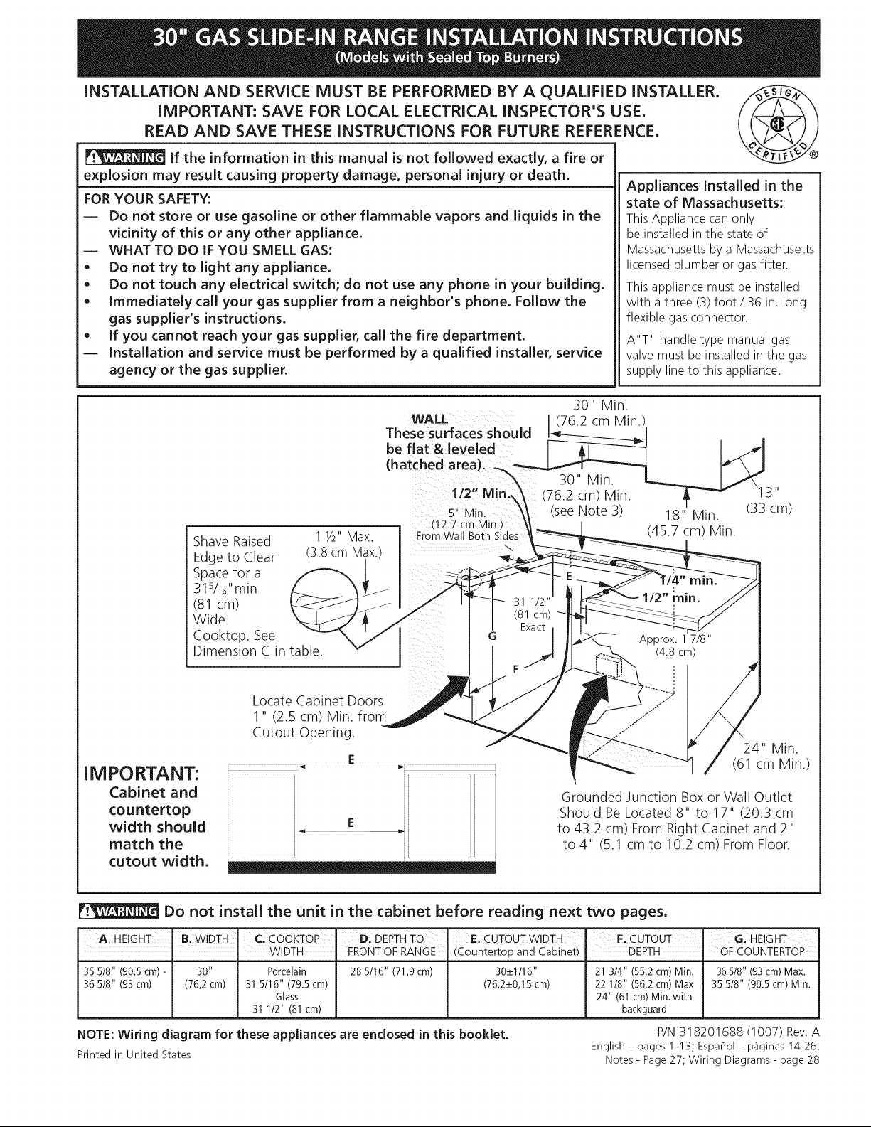
30" Min.
WA
(76.2 cm Min.
These surfaces should
be flat &leveled
(hatched area).
1
(seeNote 3) 18" Min. (33 cm)
Shave Raised
Edge to Clear
11/2"Max.
(3.8 cm Max.
Spacefor a
31s/16"min
(81 cm)
Wide
Cooktop. See
Dimension C in table.
Appliances Installed in the
state of Massachusetts:
This Appliance can only
be installed in the state of
Massachusetts by a Massachusetts
licensed plumber or gas fitter.
This appliance must be installed
with athree (3) foot / 36 in. long
flexible gas connector.
A"T" handle type manual gas
valve must be installed in the gas
supply line to this appliance.
(45.7 cm) Min.
11
Locate Cabinet Doors
1" (2.5 cm) Min. from
Cutout Opening.
IM PORTANT:
Cabinet and
countertop
width should
match the
cutout width.
Do not install the unit in the cabinet before reading next two pages.
A. HBGHT
35 518" (90.5 cm) -
36 518" (93 cm)
NOTE: Wiring diagram for these appliances are enclosed in this booklet.
Printed in United States
B. WIDTH" _.cooKToP
WIDTH
30" Porcelain
(76,2cm) 315/16" (79.5cm)
Glass
31 1/2" (81cm)
Di DEPTHTO E. CUTOUT WIDTH
FRONTOF RANGE (Countertop and Cabinet)
28 5116" (71,9cm) 30_+1116"
(76,2_+0,15cm)
24" Min.
(61 cm Min.)
Grounded Junction Box or Wall Outlet
Should Be Located 8" to 17" (20.3 cm
to 43.2 cm) From Right Cabinet and 2"
to 4" (5.1 cm to 10.2 cm) From Floor.
F: CUTOUT G. HEIGHT
DEPTH " OF COUNTERTOP
21 3/4" (55,2 cm)Min.
22 1/8" (56,2 cm)Max
24" (61 cm) Min.with
backguard
P/N 318201688 (1007) Rev. A
English- pages 1-13; Espahol- p_iginas 14-26;
Notes- Page 27; Wiring Diagrams- page 28
36 5/8" (93 cm) Max.
35 5/8" (90.5 cm) Min.
Page 2
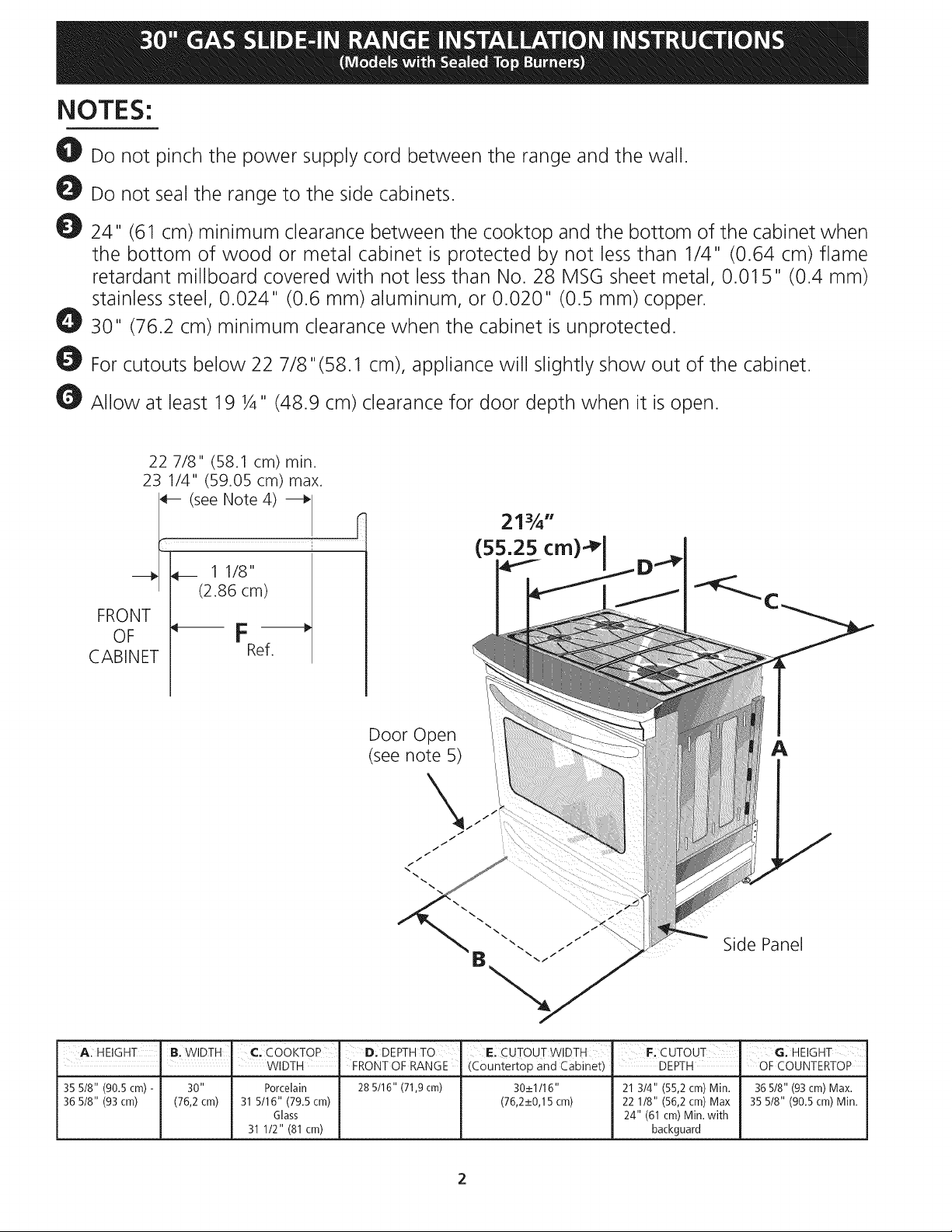
NOTES:
O! Do not pinch the power supply cord between the range and the wall.
Do not seal the range to the side cabinets.
24" (6! cm) minimum clearance between the cooktop and the bottom of the cabinet when
the bottom of wood or metal cabinet is protected by not less than 1/4" (0.64 cm) flame
retardant millboard covered with not less than No. 28 MSG sheet metal, 0.01 5" (0.4 mm)
stainless steel, 0.024" (0.6 mm) aluminum, or 0.020" (0.5 mm) copper.
30" (76.2 cm) minimum clearance when the cabinet is unprotected.
For cutouts below 22 7/8"(58.1 cm), appliance will slightly show out of the cabinet.
Allow at least 19 ¼" (48.9 cm) clearance for door depth when it is open.
22 7/8" (58.1 cm) min.
23 1/4" (59.05 cm) max.
(see Note 4)
______ 1 1/8"
(2.86 cm)
FRONT
OF _F -_
CABINET Ref.
S
Door Open
(see note 5)
A
Side Panel
A: HEIGHT B. WIDTH" C, Co©KToP" D; DEPTHT0 E. CUTOUT WIDTH F; cUTOUT' GIHEIGHT
I I WIDTH FRONTOF RANGE (Countertop and Cabinet) DEPTH OFCOUNTERTOP
35 5/8" (90.5 cm) - 30" Porcelain 28 5/16" (71,9 cm) 30_+1/16" 21 3/4" (55,2 cm) Min. 36 5/8" (93 crn) Max.
36 5/8" (93 cm) (76,2 cm) 31 5/16" (79.5 cm) (76,2_+0,15 cm) 22 1/8" (56,2 cm) Max 35 5/8" (90.5 cm) Min.
Glass 24" (61 cm) Min. with
31 1/2" (81 cm) backguard
Page 3
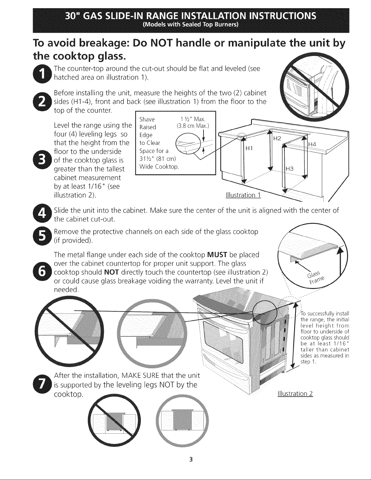
To avoid breakage: Do NOT handle or manipulate the unit by
the cooktop glass.
The counter-top around the cut-out should be flat and leveled (see
hatched area on illustration 1).
Before installing the unit, measure the heights of the two (2) cabinet
sides (H1-4), front and back (see illustration 1) from the floor to the
top of the counter•
Shave
Level the range using the
four (4)leveling legs so
that the height from the
floor to the underside
of the cooktop glass is
greater than the tallest
Raised
Edge
to Clear
Space for a
311/2" (81 cm)
Wide Cooktop.
cabinet measurement
by at least 1/16" (see
illustration 2).
Slide the unit into the cabinet. Make sure the center of the unit is aligned with the center of
the cabinet cut-out.
1 1/2"Max.
(3.8cm Max.)
Illustration 1
Remove the protective channels on each side of the glass cooktop
(if provided)•
The metal flange under each side of the cooktop MUST be placed
over the cabinet countertop for proper unit support• The glass
cooktop should NOT directly touch the countertop (see illustration 2)
or could cause glass breakage voiding the warranty• Level the unit if
needed•
After the installation, MAKE SUREthat the unit
is supported by the leveling legs NOT by the
cooktop.
successfully install
the range, the initial
level height from
floor to underside of
cooktop glass should
be at least 1/16"
taller than cabinet
sides as measured in
step 1.
Illustration 2
3
Page 4
important Notes to the Installer
1. Read all instructions contained in these installation
instructions before installing range.
2. Remove all packing material from the oven
compartments before connecting the gas and
electrical supply to the range.
3. Observe all governing codes and ordinances.
4. Besure to leave these instructions with the consumer.
5. Note: For operation at 2000 ft. elevations above see
level, appliance rating shall be reduced by 4 percent
for each additional 1000 ft.
unless you place an insulating pad or sheet of 1/4"
(10,16 cm) thick plywood between the range and
carpeting.
Make sure the wall coverings around the range
can withstand the heat generated by the range.
Do not obstruct the flow of combustion air at the
oven vent nor around the base or beneath the
lower front panel of the range. Avoid touching the
vent openings or nearby surfaces as they may become
hot while the oven is in operation. This range requires
fresh air for proper burner combustion.
important Note to the Consumer
Keep these instructions with your Use & Care Guide for
future reference.
IMPORTANT SAFETY
INSTRUCTION
Installation of this range must conform with local codes
or, in the absence of local codes, with the National Fuel
Gas Code ANSI Z223.1/NFPA .54-latest edition.
This range has been design certified by CSA
International. As with any appliance using gas and
generating heat, there are certain safety precautions you
should follow. You will find them in the Useand Care
Guide, read it carefully.
• Be sure your range is installed and grounded
properly by a qualified installer or service
technician.
This range must be electrically grounded in
accordance with local codes or, in their absence,
with the National Electrical Code ANSI/NFPA No.
70--latest edition. See Grounding Instructions.
Before installing the range in an area covered
with linoleum or any other synthetic floor
covering, make sure the floor covering can
withstand heat at least 90°F above room
temperature without shrinking, warping or
discoloring. Do not install the range over carpeting
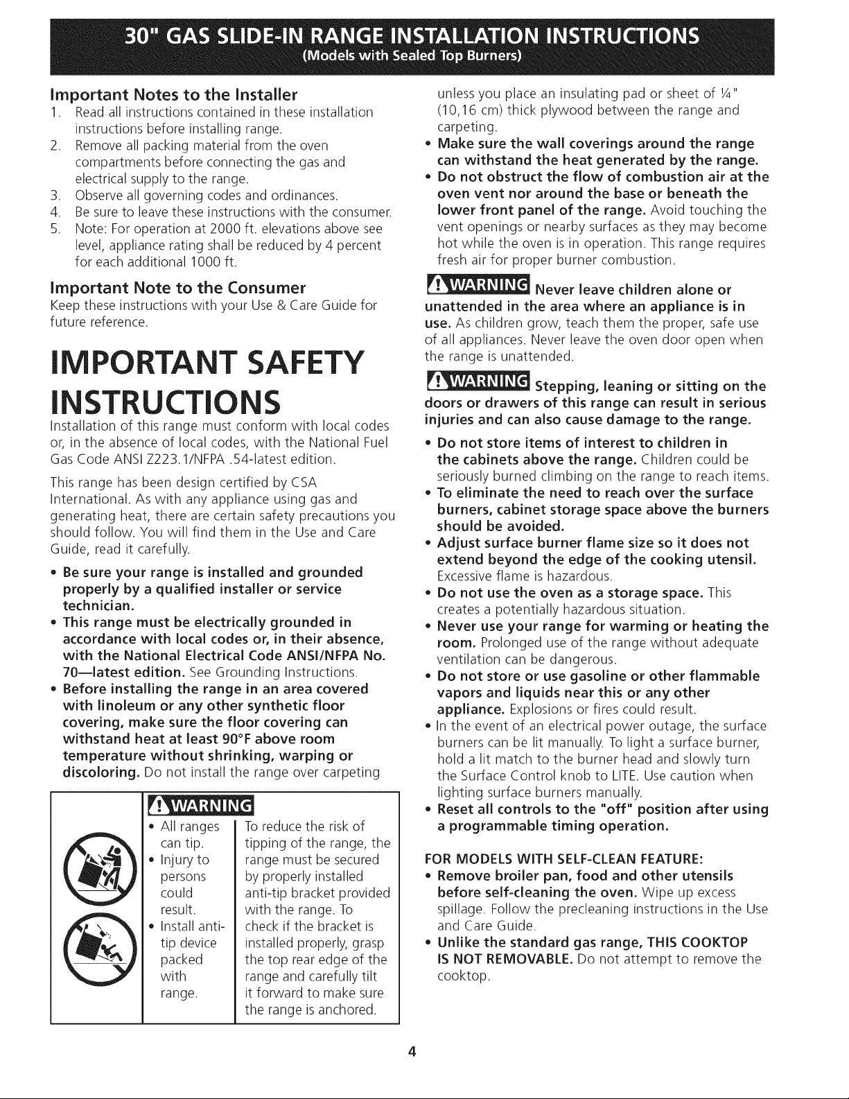
All ranges
can tip.
Injury to
persons
could
result.
Install anti-
tip device
packed
with
range.
To reduce the risk of
tipping of the range, the
range must be secured
by properly installed
anti-tip bracket provided
with the range. To
check if the bracket is
installed properly, grasp
the top rear edge of the
range and carefully tilt
it forward to make sure
the range is anchored.
Never leave children alone or
unattended in the area where an appliance is in
use. As children grow, teach them the proper, safe use
of all appliances. Never leave the oven door open when
the range is unattended.
Stepping, leaning or sitting on the
doors or drawers of this range can result in serious
injuries and can also cause damage to the range.
Do not store items of interest to children in
the cabinets above the range. Children could be
seriously burned climbing on the range to reach items.
To eliminate the need to reach over the surface
burners, cabinet storage space above the burners
should be avoided.
Adjust surface burner flame size so it does not
extend beyond the edge of the cooking utensil.
Excessiveflame is hazardous.
Do not use the oven as a storage space. This
creates a potentially hazardous situation.
Never use your range for warming or heating the
room. Prolonged use of the range without adequate
ventilation can be dangerous.
Do not store or use gasoline or other flammable
vapors and liquids near this or any other
appliance. Explosions or fires could result.
In the event of an electrical power outage, the surface
burners can be lit manually. To light a surface burner,
hold a lit match to the burner head and slowly turn
the Surface Control knob to LITE.Use caution when
lighting surface burners manually.
Reset all controls to the "off" position after using
a programmable timing operation.
FOR MODELS WITH SELF=CLEAN FEATURE:
Remove broiler pan, food and other utensils
before self=cleaning the oven. Wipe up excess
spillage. Follow the predeaning instructions in the Use
and Care Guide.
Unlike the standard gas range, THIS COOKTOP
IS NOT REMOVABLE, Do not attempt to remove the
cooktop.
4
Page 5
Cabinet Construction
Toeliminate the risk of cabinet burns
and fire, do not have cabinet storage space above the
range. If there is cabinet storage space above range,
reduce risk by installing a range hood that projects
horizontally a minimum of 5" (12.7 cm) beyond the
bottom of the cabinet.
Countertop Preparation
• The cooktop sides of the range fit over the cutout
edge of your countertop.
• If you have a square finish (flat) countertop, no
countertop preparation is required. Cooktop sides lay
directly on edge of countertop.
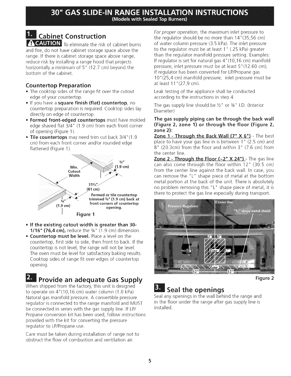
• Formed front-edged countertops must have molded
edge shaved flat 3/4" (1.9 cm) from each front corner
of opening (Figure 1).
• Tile countertops may need trim cut back 3/4"(1.9
cm) from each front corner and/or rounded edge
flattened (Figure 1).
311/2,,_ _
(81cm)
Formed or tile countertop
trimmed _A" (1_9 cm) back at
front corners of countertop
(1.9 cm) opening,
I Figure I
Forproper operation, the maximum inlet pressure to
the regulator should be no more than 14"(35,56 cm)
of water column pressure (3.5 kPa). The inlet pressure
to the regulator must be at least 1" (.25 kPa) greater
than the regulator manifold pressure setting. Examples:
If regulator is set for natural gas 4" (10,16 cm) manifold
pressure, inlet pressure must be at least 5"(12.60 cm);
if regulator has been converted for LP/Propane gas
10"(25,4 cm) manifold pressure, inlet pressure must be
at least 11 "(27,9 cm).
Leak testing of the appliance shall be conducted
according to the instructions in step 4.
The gas supply line should be 1/2"or 3A" I.D. (Interior
Diameter)
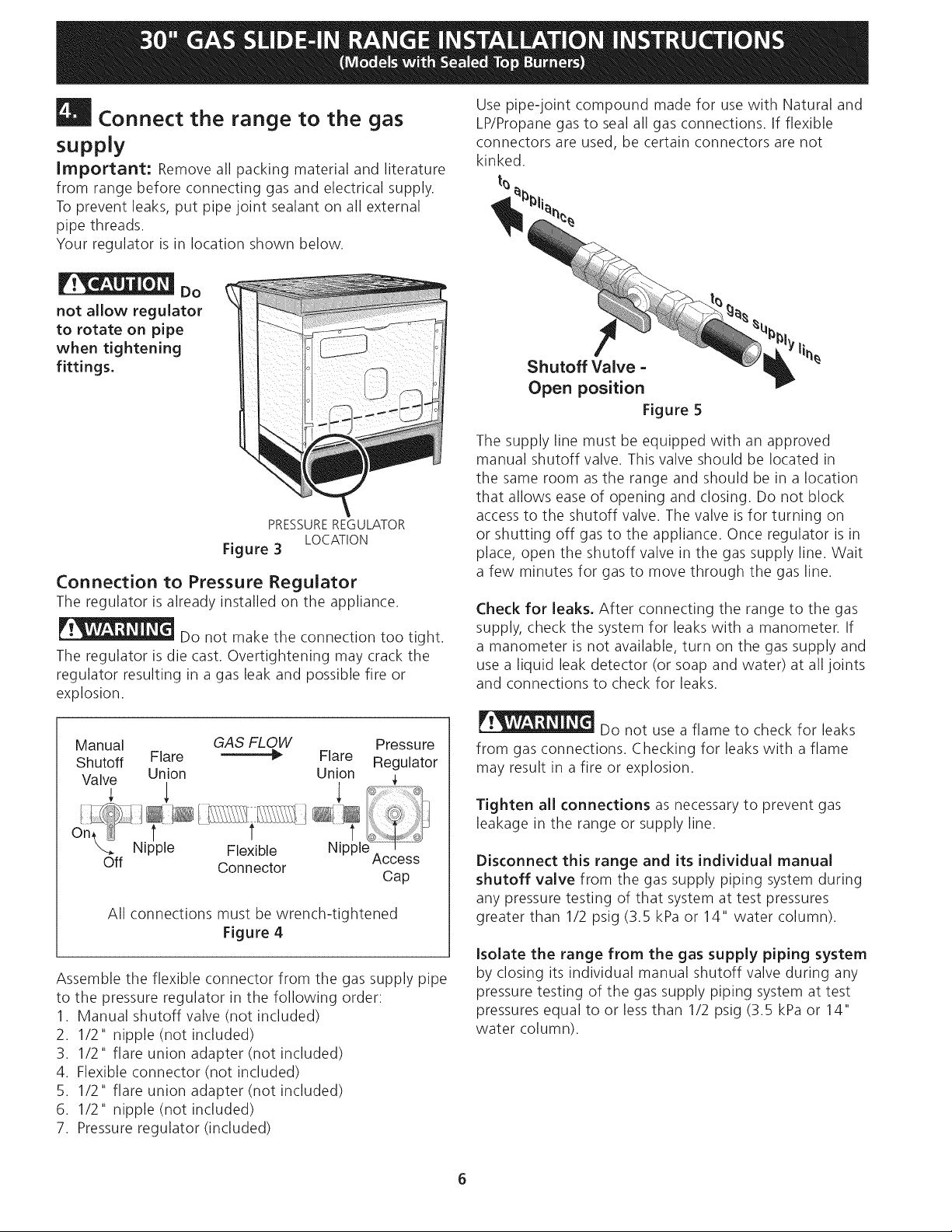
The gas supply piping can be through the back wall
(Figure 2, zone 1) or through the floor (Figure 2,
zone 2):
Zone I - Through the Back Wall (7" X 6") - The best
place to have your gas line in is between 1" (2.5 cm) and
8" (20.3cm) from the floor and within 3" (7.6 cm) from
the center line.
Zone 2 = Through the Floor (~2" X 24") - The gas line
can also come through the floor within 12" (30.5 cm)
from the center line against the back wall. In case, you
can remove the "L" shape piece of metal at the bottom
metal portion at the back of the unit. There is absolutely
no problem removing this "L" shape piece of metal, it is
there to protect the gas line especially during transport.
• If the existing cutout width is greater than 30-
1/16" (76,4 cm), reduce the 3A" (1.9 cm) dimension.
• Countertop must be level, Place a level on the
countertop, first side to side, then front to back. If the
countertop is not level, the range will not be level.
The oven must be level for satisfactory baking results.
Cooktop sides of range fit over edges of countertop
opening.
m
Provide an adequate Gas Supply
When shipped from the factory, this unit is designed
to operate on 4"(10,16 cm) water column (1.0 kPa)
Natural gas manifold pressure. A convertible pressure
regulator is connected to the range manifold and MUST
be connected in series with the gas supply line. If LP/
Propane conversion kit has been used, follow instructions
provided with the kit for converting the pressure
regulator to LP/Propane use.
Care must be taken during installation of range not to
obstruct the flow of combustion and ventilation air.
Figure 2
Seal the openings
Seal any openings in the wall behind the range and
in the floor under the range after gas supply line is
installed.
Page 6
m
| Connect the range to the gas
supply
Important: Remove all packing material and literature
from range before connecting gas and electrical supply.
To prevent leaks, put pipe joint sealant on all external
pipe threads.
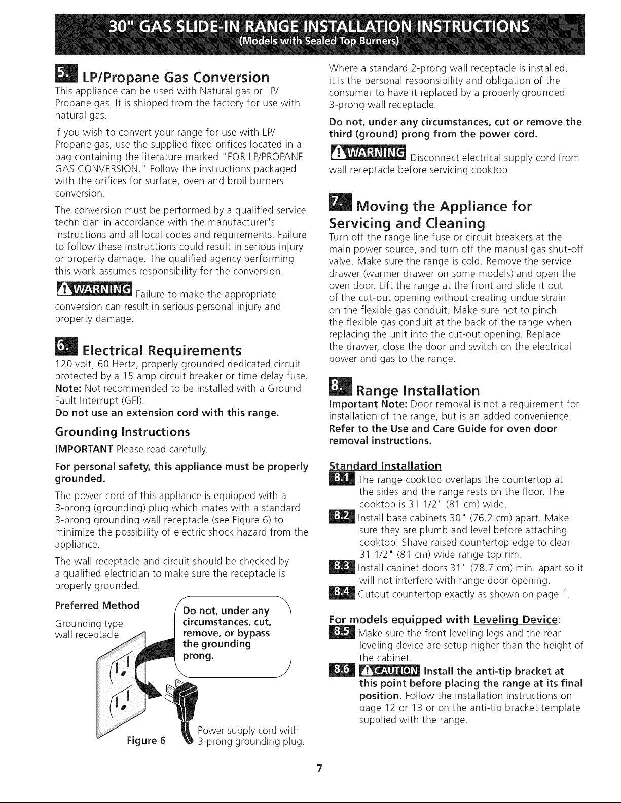
Your regulator is in location shown below.
Do
not allow regulator
to rotate on pipe
when tightening
fittings.
PRESSUREREGULATOR
LOCATION
Figure 3
Connection to Pressure Regulator
The regulator is already installed on the appliance.
_Do not make the connection too tight.
The regulator is die cast. Overtightening may crack the
regulator resulting in a gas leak and possible fire or
explosion.
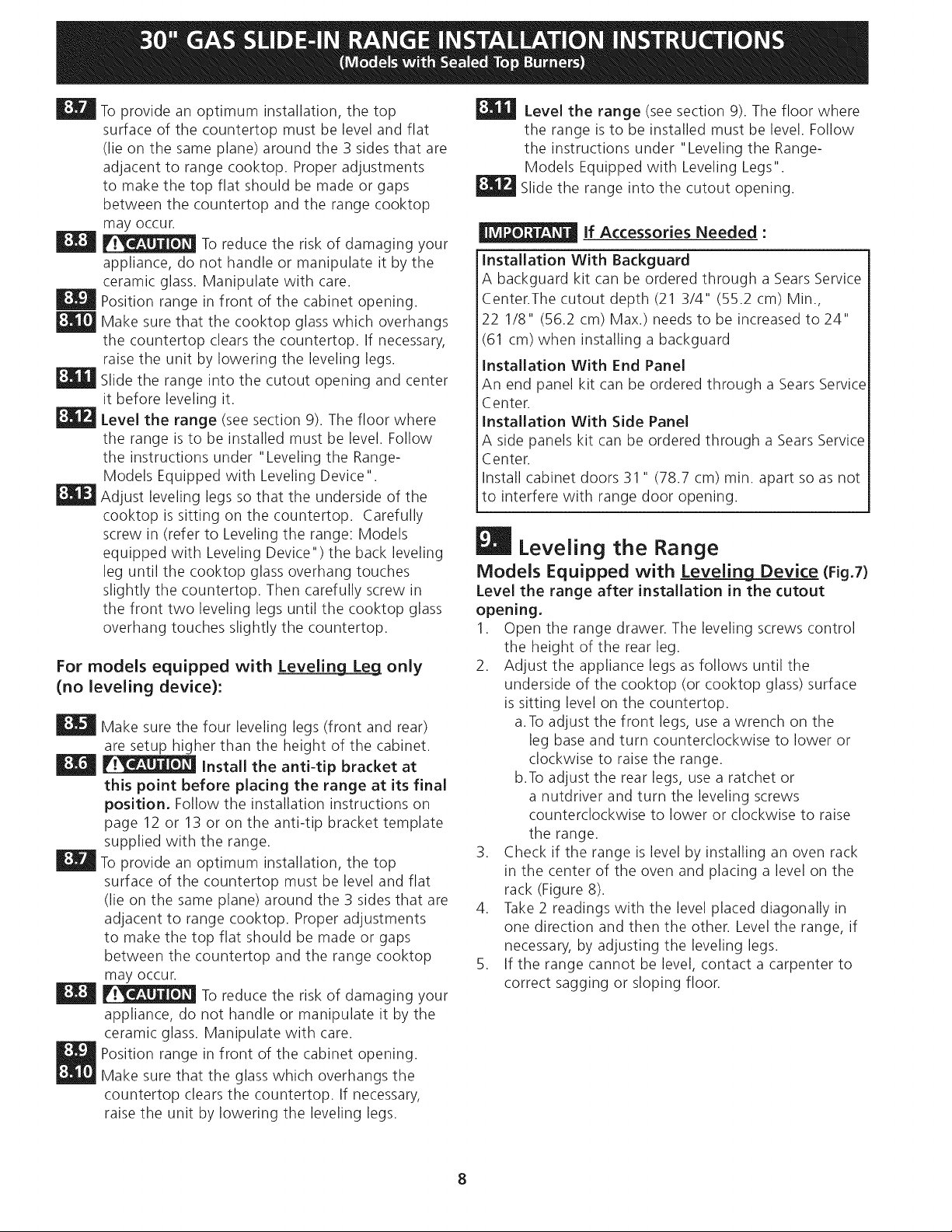
Use pipe-joint compound made for use with Natural and
LP/Propane gas to seal all gas connections. If flexible
connectors are used, be certain connectors are not
kinked.
t_
Shutoff Valve -
Open position
Figure 5
The supply line must be equipped with an approved
manual shutoff valve. This valve should be located in
the same room as the range and should be in a location
that allows ease of opening and closing. Do not block
access to the shutoff valve. The valve is for turning on
or shutting off gas to the appliance. Once regulator is in
place, open the shutoff valve in the gas supply line. Wait
a few minutes for gas to move through the gas line.
Check for leaks, After connecting the range to the gas
supply, check the system for leaks with a manometer. If
a manometer is not available, turn on the gas supply and
use a liquid leak detector (or soap and water) at all joints
and connections to check for leaks.
Manual GAS FLOW Pressure
Shutoff Flare _I_ Flare Regulator
Valve Union Union _,
Off Connector
All connections must be wrench-tightened
Figure 4
Assemble the flexible connector from the gas supply pipe
to the pressure regulator in the following order:
1. Manual shutoff valve (not included)
2. 1/2" nipple (not included)
3. 1/2" flare union adapter (not included
4. Flexible connector (not included)
5. 1/2" flare union adapter (not included
6. 1/2" nipple (not included)
7. Pressure regulator (included)
Access
Cap
Do not use a flame to check for leaks
from gas connections. Checking for leaks with a flame
may result in a fire or explosion.
Tighten all connections as necessary to prevent gas
leakage in the range or supply line.
Disconnect this range and its individual manual
shutoff valve from the gas supply piping system during
any pressure testing of that system at test pressures
greater than 1/2 psig (3.5 kPa or 14" water column).
Isolate the range from the gas supply piping system
by closing its individual manual shutoff valve during any
pressure testing of the gas supply piping system at test
pressures equal to or less than 1/2 psig (3.5 kPa or 14"
water column).
Page 7
m
LP/Propane Gas Conversion
This appliance can be used with Natural gas or LID/
Propane gas. It is shipped from the factory for use with
natural gas.
If you wish to convert your range for use with LP/
Propane gas, use the supplied fixed orifices located in a
bag containing the literature marked "FOR LP/PROPANE
GAS CONVERSION." Follow the instructions packaged
with the orifices for surface, oven and broil burners
conversion.
The conversion must be performed by a qualified service
technician in accordance with the manufacturer's
instructions and all local codes and requirements. Failure
to follow these instructions could result in serious injury
or property damage. The qualified agency performing
this work assumes responsibility for the conversion.
Failure to make the appropriate
conversion can result in serious personal injury and
property damage.
| Electrical Requirements
120 volt, 60 Hertz, properly grounded dedicated circuit
protected by a 15 amp circuit breaker or time delay fuse.
Note: Not recommended to be installed with a Ground
Fault Interrupt (GFI).
Do not use an extension cord with this range.
Grounding Instructions
IMPORTANT Pleaseread carefully.
For personal safety, this appliance must be properly
grounded.
The power cord of this appliance isequipped with a
3-prong (grounding) plug which mates with a standard
3-prong grounding wall receptacle (see Figure 6) to
minimize the possibility of electric shock hazard from the
appliance.
The wall receptacle and circuit should be checked by
a qualified electrician to make sure the receptacle is
properly grounded.
Preferred Method Do not, under any -_
Grounding type circumstances, cut,
wall receptacle remove, or bypass
the grounding
prong.
Power supply cord with
Figure 6
3-prong grounding plug.
Where a standard 2-prong wall receptacle is installed,
it is the personal responsibility and obligation of the
consumer to have it replaced by a properly grounded
3-prong wall receptacle.
Do not, under any circumstances, cut or remove the
third (ground) prong from the power cord.
Disconnect electrical supply cord from
wall receptacle before servicing cooktop.
Moving the Appliance for
Servicing and Cleaning
Turn off the range line fuse or circuit breakers at the
main power source, and turn off the manual gas shut-off
valve. Make sure the range is cold. Remove the service
drawer (warmer drawer on some models) and open the
oven door. Lift the range at the front and slide it out
of the cut-out opening without creating undue strain
on the flexible gas conduit. Make sure not to pinch
the flexible gas conduit at the back of the range when
replacing the unit into the cut-out opening. Replace
the drawer, close the door and switch on the electrical
power and gas to the range.
Range Installation
Important Note: Door removal is not a requirement for
installation of the range, but is an added convenience.
Refer to the Use and Care Guide for oven door
removal instructions.
Standard Installation
The range cooktop overlaps the countertop at
the sides and the range rests on the floor. The
cooktop is 31 1/2" (81 cm) wide.
| Install base cabinets 30" (76.2 cm) apart. Make
sure they are plumb and level before attaching
cooktop. Shave raised countertop edge to clear
31 1/2" (81 cm) wide range top rim.
Install cabinet doors 31 " (78.7 cm) min. apart so it
will not interfere with range door opening.
Cutout countertop exactly as shown on page 1.
For models equipped with Leveling Device:
Make sure the front leveling legs and the rear
leveling device are setup higher than the height of
the cabinet.
_:_ _ Install the anti-tip bracket at
this point before placing the range at its final
position. Follow the installation instructions on
page 12 or 13 or on the anti-tip bracket template
supplied with the range.
7
Page 8
Toprovideanoptimuminstallation,thetop
surfaceofthecountertopmustbelevelandflat
(lieonthesameplane)aroundthe3 sidesthatare
adjacentto rangecooktop.Properadjustments
tomakethetopflatshouldbemadeorgaps
betweenthecountertopandtherangecooktop
mayoccur.
_ To reduce the risk of damaging your
appliance, do not handle or manipulate it by the
ceramic glass. Manipulate with care.
| Position range in front of the cabinet opening.
| Make sure that the cooktop glass which overhangs
the countertop clears the countertop. If necessary,
raise the unit by lowering the leveling legs.
| Slide the range into the cutout opening and center
it before leveling it.
Level the range (see section 9). The floor where
the range isto be installed must be level. Follow
the instructions under "Leveling the Range-
Models Equipped with Leveling Device".
Adjust leveling legs so that the underside of the
cooktop is sitting on the countertop. Carefully
screw in (refer to Leveling the range: Models
equipped with Leveling Device") the back leveling
leg until the cooktop glass overhang touches
slightly the countertop. Then carefully screw in
the front two leveling legs until the cooktop glass
overhang touches slightly the countertop.
For models equipped with Leveling Leg only
(no leveling device):
Make sure the four leveling legs (front and rear)
are setup higher than the height of the cabinet.
_:_ _ Install the anti-tip bracket at
this point before placing the range at its final
position. Follow the installation instructions on
page 12 or 13 or on the anti-tip bracket template
supplied with the range.
To provide an optimum installation, the top
surface of the countertop must be level and flat
(lie on the same plane) around the 3 sides that are
adjacent to range cooktop. Proper adjustments
to make the top flat should be made or gaps
between the countertop and the range cooktop
may occur.
_ To reduce the risk of damaging your
appliance, do not handle or manipulate it by the
ceramic glass. Manipulate with care.
Position range in front of the cabinet opening.
Make sure that the glass which overhangs the
countertop clears the countertop. If necessary,
raise the unit by lowering the leveling legs.
Level the range (see section 9). The floor where
the range isto be installed must be level. Follow
the instructions under "Leveling the Range-
Models Equipped with Leveling Legs".
Slide the range into the cutout opening.
If Accessories Needed :
Installation With Backguard
A backguard kit can be ordered through a Sears Service
Center.The cutout depth (21 3/4" (55.2 cm) Min.,
22 1/8" (56.2 cm) Max.) needs to be increased to 24"
(61 cm) when installing a backguard
Installation With End Panel
An end panel kit can be ordered through a Sears Service
Center.
Installation With Side Panel
A side panels kit can be ordered through a Sears Service
Center.
Install cabinet doors 31 " (78.7 cm) min. apart so as not
to interfere with range door opening.
Leveling the Range
Models Equipped with Leveling Device (Fig.7)
Level the range after installation in the cutout
opening.
1. Open the range drawer. The leveling screws control
the height of the rear leg.
2. Adjust the appliance legs as follows until the
underside of the cooktop (or cooktop glass) surface
is sitting level on the countertop.
a.To adjust the front legs, use a wrench on the
leg base and turn counterclockwise to lower or
clockwise to raise the range.
b.To adjust the rear legs, use a ratchet or
a nutdriver and turn the leveling screws
counterclockwise to lower or clockwise to raise
the range.
3. Check if the range is level by installing an oven rack
in the center of the oven and placing a level on the
rack (Figure 8).
4. Take2 readings with the level placed diagonally in
one direction and then the other. Level the range, if
necessary, by adjusting the leveling legs.
5. If the range cannot be level, contact a carpenter to
correct sagging or sloping floor.
Page 9
Leveling
Font
Leveling
Leg
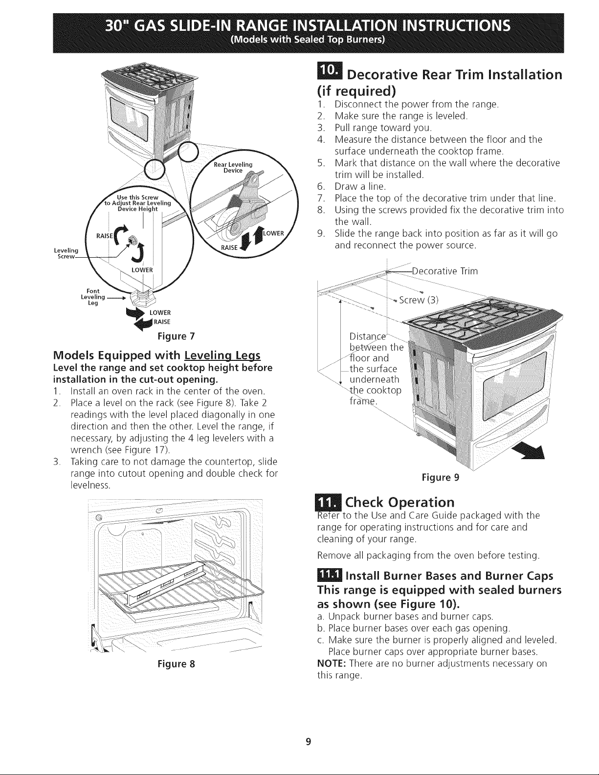
Decorative Rear Trim Installation
(if required)
1. Disconnect the power from the range.
2. Make sure the range is leveled.
3. Pull range toward you.
4. Measure the distance between the floor and the
surface underneath the cooktop frame.
5. Mark that distance on the wall where the decorative
trim will be installed.
6. Draw a line.
7. Place the top of the decorative trim under that line.
8. Using the screws provided fix the decorative trim into
the wall.
9. Slide the range back into position as far as it will go
and reconnect the power source.
Trim
oScrew (3)
LOWER
RAISE
Figure 7
Models Equipped with Levelin_
Level the range and set cooktop height before
installation in the cut-out opening.
1. Install an oven rack in the center of the oven.
2. Place a level on the rack (see Figure 8). Take 2
readings with the level placed diagonally in one
direction and then the other. Level the range, if
necessary, by adjusting the 4 leg levelers with a
wrench (see Figure 17).
3. Taking care to not damage the countertop, slide
range into cutout opening and double check for
levelness.
Figure 8
:loor and
surface
underneath
"\the cooktop
fra_
Figure 9
Check Operation
Re-
to the Use and Care Guide packaged with the
range for operating instructions and for care and
cleaning of your range.
Remove all packaging from the oven before testing.
| Install Burner Bases and Burner Caps
This range is equipped with sealed burners
as shown (see Figure 10).
a. Unpack burner bases and burner caps.
b. Place burner bases over each gas opening.
c. Make sure the burner is properly aligned and leveled.
Place burner caps over appropriate burner bases.
NOTE: There are no burner adjustments necessary on
this range.
9
Page 10

Electrode ................ J
Figure 10
Turn on Electrical Power and Open
Main Shutoff Gas Valve
Check the Igniters
Operation of electric igniters should be checked after
range and supply line connectors have been carefully
checked for leaks, and range has been connected to
electric power. Tocheck for proper lighting:
a. Push in and turn a surface burner knob to the LITE
position. You will hear the igniter sparking.
b. The surface burner should light when gas is available
to the top burner. Each burner should light within
four (4) seconds after air has been purged from supply
lines. Visually check that burner has lit.
c. Once the burner lights, the control knob should be
rotated out of the LITEposition.
There are separate ignition devices for each burner. Try
each knob separately until all burner valves have been
checked.
Adjust the "LOW" Setting of Surface
Burner Valves (see Figure 11)
a. Push in and turn each control to LITEuntil burner
ignites.
b. Quickly turn knob to LOWEST POSITION.
c. If burner goes out, readjust valve asfollows:
Reset control to OFF.Remove the surface burner
control knob, insert a thin-bladed screw driver into the
hollow valve stem and engage the slotted screw inside.
Flame size can be increased or decreased with the
turn of the screw. Adjust flame until you can quickly
turn knob from LITEto LOWESTPOSITIONwithout
extinguishing the flame. Flame should be as small as
possible without going out.
Figure 11
Operation of Oven Burners and Oven
Adjustments
11.5.1 Electric Ignition Burners
Operation of electric igniters should be checked after
range and supply line connectors have been carefully
checked for leaks, and range has been connected to
electric power.
The oven burner is equipped with an electric control
system as well as an electric oven burner igniter. If your
model isequipped with a waist-high broil burner igniter,
it will also have an electric burner igniter. These control
systems require no adjustment. When the oven isset to
operate, current will flow to the igniter. It will "glow"
similar to a light bulb. When the igniter has reached
a temperature sufficient to ignite gas, the electrically
controlled oven valve will open and flame will appear
at the oven burner. There is atime lapse from 30 to 60
seconds after thermostat is turned ON before the flame
appears at the oven burner. When the oven reaches the
display setting, the glowing igniter will go off. The burner
flame will go "out" in 20 to 30 seconds after igniter goes
"OFF". Tomaintain any given oven temperature, this cycle
will continue as long as the display is set to operate.
After removing all packing materials and literature from
the oven:
a) Set the oven to BAKEat 300% See Use & Care Guide
for operating instructions.
b) Within 60 seconds the oven burner should ignite.
Check for proper flame, and allow the burner to cycle
once. Reset controls to off.
c) If your model is equipped with a high-waist broiler,
set oven to broil. See Use & Care Guide for operating
instructions.
d) Within 60 seconds the broil burner should ignite. Check
for proper flame. Resetcontrols to off.
10
Page 11

L wer
OvenBaffle
Waist-HighBurner
Shutter
(removable),
!1
LowerOvenBottom
_l--Air Shutter (removable)
Figure12
11.5.2Air Shutter-OvenBurner
Theapproximateovenburnerflamelengthis1inch
(distinctinnerconeofblueflame).
Todetermineiftheovenburnerflameisproper,removethe
ovenbottomandburnerbaffleandsettheoventobakeat
300%
Toremovetheovenbottom,removeovenholddown
screwsatrearofovenbottom.Pullupatrear,disengage
frontofovenbottomfromovenfrontframe,andpullthe
ovenbottomoutof theoven.Removeburnerbafflesothat
burnerflamecanbeobserved.
Iftheflameisyellow,increaseairshutteropeningsize(see
"2" inFigure13).Iftheentireflameisblue,reducetheair
shutteropeningsize.
Toadjustframeloosenlockscrew(see"3" inFigure13),
repositionairshutter,andtightenlockscrew.Replaceoven
bottom.
When All Hookups are Complete
MakesureallcontrolsareleftintheOFFposition.
Makesuretheflowofcombustionandventilationairto
therangeisunobstructed.
Model and Serial Number Location
The serial plate is located on the oven front frame behind
the oven door (some models) or on the drawer side
frame (some models).
When ordering parts for or making inquiries about your
range, always be sure to include the model and serial
numbers and a lot number or letter from the serial plate
on your range.
Your serial plate also tells you the rating of the burners,
the type of fuel and the pressure the range was adjusted
for when it left the factory.
Before You Call for Service
Read the Before You Call Checklist and operating
instructions in your Use and Care Guide. It may save you
time and expense. The list includes common occurrences
that are not the result of defective workmanship or
materials in this appliance.
Refer to your Use & Care Guide for Sears service phone
numbers or call 1-800-4-MY-HOME®.
Burner Tube
(_ Lock Screw_
Air Shutter--II_!
Orifice Hood
Figure 13
11.5.3 Air Shutter-Broil Burner
The approximate flame length of the burner is 1 inch
(distinct inner cone of blue flame). Todetermine if the broil
burner flame is proper, set the oven to broil. If flame is
yellow, increase air shutter opening size (see "2" in Figure
13 ). If the entire flame is blue, reduce the air shutter
opening size. Toadjust, loosen lock screw (see "3" in
Figure 13), reposition air shutter, and tighten lock screw.
11
Page 12

Anti-Tip Brackets Installation
instructions
ModeJs Equipped with Leveling Device
To reduce the risk of tipping of the
range, the range must be secured to the floor by properly
installed anti-tip bracket and screws packed with the
range. These parts are located in the oven. Failureto
install the anti-tip bracket will allow the range to tip over
if excessive weight is placed on an open door or if a child
climbs upon it. Serious injury might result from spilled hot
liquids or from the range itself.
Follow the instructions below to install the anti-tip
brackets.
If range is ever moved to a different location, the anti-
tip brackets must also be moved and installed with the
range.
Tools Required:
Adjustable Wrench
Ratchet
Drill & 1/8"(0,32 cm) bit
5/16" (0,8 cm) Nutdriver
Level
The anti-tip bracket attaches to the floor at the back of
the range to prevent range from tipping. When fastening
bracket to the floor, be sure that screws do not penetrate
electrical wiring or plumbing. The screws provided will
work in either wood or concrete.
1. Draw a center line (CL) on the floor where the range
should be installed. Also draw a line on the floor at
the range back position if there is no wall.
2. Unfold paper template and place it flat on the floor
with the right rear corner positioned exactly on the
intersection of the center and back lines you just drew
before. (Use the diagram below to locate brackets if
template is not available (Figure 14)).
3. Mark on the floor the location of the 4 mounting
holes shown on the template. For easier installation,
3/16"(0,48 cm) diameter pilot holes 1/2"(1,27 cm)
deep can be drilled into the floor.
4. Remove template and place bracket on floor. Line up
holes in bracket with marks on floor and attach with
4 screws provided. Bracket must be secured to solid
floor (Figure 16). If attaching to concrete floor, first
drill 3/16" (0,48 cm) dia. pilot holes using masonry drill
bit.
5. Besure the 4 leveling legs are at the highest position
they can be.
6. Slide range into place making sure structure of the
range is trapped by the anti-tip bracket (Figure 15).
Lower the range by adjusting the 4 leveling legs until
the underside of the cooktop is sitting level on the
countertop. Refer to "Leveling the Range" section.
7. After installation, verify that the anti-tip bracket is
engaged by grasping the top rear edge of the range
and carefully attempt to tilt it forward to make sure
range is properly anchored.
i}
i}
i}
i}
i}
Figure 14
Floor Mount_
Screws
Figure 15
BACK
12
Page 13

ped with Leveli_
To reduce the risk of tipping of
the range, the range must be secured to the floor by
properly installed anti-tip brackets and screws packed
with the range. These parts are located in a plastic bag in
the oven. Failure to install the anti-tip brackets will allow
the range to tip over if excessive weight is placed on
an open door or if a child climbs upon it. Serious injury
might result from spilled hot liquids or from the range
itself.
Follow the instructions below to install the anti-tip
brackets.
If range is ever moved to a different location, the anti-
tip brackets must also be moved and installed with the
range. To check for proper installation, see step 5.
Tools Required:
5/16" (0,79 cm) Nutdriver or Flat Head Screwdriver
Adjustable Wrench
Electric Drill
3/16"(0, cm) Diameter Drill Bit
3/16"(0, cm) Diameter Masonry Drill Bit (if installing in
concrete
Brackets attach to the floor at the back of the range to
hold both rear leg levelers. When fastening to the floor,
be sure that screws do not penetrate electrical wiring or
plumbing. The screws provided will work in either wood
or concrete.
Anti-tip Bracket
1. Unfold paper template and place it flat on the floor
with the back and side edges positioned exactly
where the back and sides of range will be located
when installed. (Use the diagram below to locate
brackets if template is not available. (Figure 16))
2. Mark on the floor the location of the 4 mounting
holes shown on the template. For easier installation,
3/16" (0.5 cm) diameter pilot holes 1/2" (1.3 cm)
deep can be drilled into the floor.
3. Remove template and place brackets on floor
with turned up flange to the front. Line up holes
in brackets with marks on floor and attach with 4
screws provided. Brackets must be secured to solid
floor. If attaching to concrete floor, first drill 3/16"
(0.5 cm) dia. pilot holes using a masonry drill bit.
4. Level range if necessary, by adjusting 4 leg levelers
with wrench (Figure 17). A minimum clearance of
1/8" (0.8 cm) is required between the bottom of the
range and the rear leg levelers to allow room for the
anti-tip brackets.
5. Slide range into place making sure rear legs are
trapped by ends of brackets. Range may need to
be shifted slightly to one side as it is being pushed
back to allow rear legs to slide under brackets. You
may also grasp the top rear edge of the range and
carefully attempt to tilt it forward to make sure
range is properly anchored.
BackEdgeof Range /
or RearWall _41€/
C /- "--.. "...........-.
: .-9 1/8" _. 18'_ ">" _ .....
<--_,_.>_ (23.2 cm) " _(46.4 cm)
Anti-tip Bracket "--. _(71.4cm)
(CL = Center line)
Figure 16
(Rearwidth of range
with bodysides)
Figure 17
SlideBack
13
Page 14

LA INSTALACION Y EL SEP,VICIO DEBEN SEP, EFECTUADOS POP, UN INSTALADOP, CAUFICADO.
IMPOP,TANTE: GUAP,DE ESTAS INSTP,UCCIONES PAP,A USO DEL INSPECTOR LOCAL DE /__s jo__..
ELECTP,ICIDAD. LEA Y GUAP,DE ESTAS INSTP,UCCIONES PAP,A P,EFEP,ENCIA FUTUP,A.
Sila informaci6n contenida en este manual no es seguida
exactamente, puede ocurrir un incendioo explosion causandodaffos materiales, l.._/_
lesion personalo la muerte.
PARASU SEGURIDAD:
-- No almacene ni utilice gasolina u otros vapores y liquidos inflamables en la
proximidad de _ste o de cualquier otro artefacto.
-- QUEDEBEHACERSIPERClBEOLORA GAS:
• No trate de encender ningun artefacto.
• No toque ningun interruptor el6ctrico; no use ningun tel6fono en su
edificio.
• Llame a su proveedor de gas desde el tel6fono de un vecino. Siga las
instrucdones del proveedor de gas.
• Si no logra comunkarse con su proveedor de gas, flame al departamento
de bomberos.
-- La instalad6n y el servMo de mantenimiento deben ser efectuados por un
instalador calificado, la agenda de servkio o el proveedor de gas.
PARED
La superfide debe
estar plana y nive!ada
(area sornb
1/2" Min.i
Min. 5"
(!2.TCm) delaPaied;
Acepille el borde
ambos lados...
subido a que
deje espacio
para un borde
31Y2" (81 cm)de
anchura de estufa
31 1/2"
(81 cm)
Exacto
Aparatos Instalados en el estado
de Massachusetts;
EsteAparato s61o puede ser instalado
en el estado de Massachusetts por un
plomero o ajustador de gas licenciado
de Massachusett.
Esteaparato se debe instalar con un
largo conector flexible de gas de tres (3)
pies/36 pulgadas.
Una wilvula manual de gas de tipo
manija de forma de "T" se debe instalar
en la Ifnea del suministro de gas de este
aparato.
30" Min.
76.2 cm Min.)
30" Min.
(76.2 cm Min.) 13"
(v6a la nota 3) (33 cm)
18" Min.
(45.7 cm) Min.
Approx. 1 7/8"
(4.8 cm)
Localice las puertas del
armario 1"(2.5 cm) min
del hueco de la abertura.
IMPORTANTE: El
ancho de la cubierta
y el armario debe
de ser igual al ancho
E
del corte.
ll_J___No instale la unidad en el gabinete si no ha lado esta p_qgina.
A ALTURA ' B:ANcNo " C. ANCH0 DE D. PROFUNDIDAD A
I LA PLANCHA DE LA FRENTEDE LA
- COC NAR - ESTUFA
355/8" (90.5cm) - 30" Porcelana 28 5/16" (71,9 cm)
365/8" (93cm) (76,2 cm) 315/16" (79.5cm)
Vidrio
31 1/2" (81cm)
NOTA: Se adjunta el diagrama de cables de esta codna al final de este libreta.
Impreso en los Estados Unidos
E. ANc HO F. PROFUNDIDAD DE G[ ALTURA DEL
DE RECORTADO RECORTADO .... MOSTRADOR
(cubierta y armario) i
30_+1/16" 21 3/4" (55,2 cm)Min. 36 5/8" (93cm)Max.
(76,2_+0,15cm) 22 1/8" (56,2 cm) Max 35 5/8" (90.5cm) Min.
Notas - p_igina 27; Diagrama de la instalaci6n akimbrica - p_igina 28
La caj de empalmesoel enchufe con
puesta a tierra deberia situarse de 8" a 17"
(20.3 cm a 43.2 cm) del armario derecho y
de 2" a 4" (5.1 cm a 10.2 cm) del suelo.
24" (61cm) Min. conun
protectortrasero.
English- pages 1-13; Espahol- p_iginas 14-26;
°°°÷,°"
24" Min.
(61 cm Min.)
/
P/N 318201688 (1007) Rev. A
Page 15

NOTAS:
No pellizque el cord6n electrico entre la estufa y la pared.
No selle la estufa a los armarios de lado.
Un espacio minimo de 24" (61 cm) entre la superficie de la estufa y el fondo del
armario esto cuando el fondo del armario de madera o metal est,1protegido pot
no menos de 1/4" (0.64 cm) de madera resistente al fuego cubierta pot una I_imina
met_ilica de MSG, n0mero 28, 0.01 5" (0.4 mm) de acero inoxidable, 0.024" (0.6
mm) aluminio, 6 0.020" (0.5 mm) de cobre.
Un espacio minimo de 30" (76.2 cm) cuando el armario no este protegido.
Para los recortados menos que 22 7/8", el electrodomestico apareceria ligeramente
en el exterior del armario.
Deje pot los 19 ¼" (48.9 cm) de espacio libre para la profundidad de la puerta
cuando este abierta.
22 7/8" (58.1 cm) min.
23 1/4" (59.05 cm) max.
÷ (yea la nota 4) ÷ r"
PARTE
DELANTERA
DEL
ARMARIO
r I
1 1/8"
_(2.86 cm)
Ref.
Panel lateral
A ALTURA B. ANcH0 c. ANCHO DE D: PROFUNDIDAD A
LA PLANCHA DE LA FRENTEDE LA
- - COCINAR " ESTUFA
355/8" (90.5cm) - 30" Porcelana 28 5/16" (71,9cm)
365/8" (93cm) (76,2 cm) 315/16" (79.5cm)
Vidrio
31 1/2" (81cm)
E. ANCHO F: PROFUNDIDAD DE G. ALTURA DEL
DE RECORTADO RECORTADO MOSTRADOR
(cubierta y armario) • -
30_+1/16" 21 3/4" (55,2 cm)Min. 36 5/8" (93cm)Max.
(76,2_+0,15cm) 22 1/8" (56,2 cm) Max 35 5/8" (90.5cm) Min.
24" (61cm) Min. conun
protectortrasero.
15
Page 16

Para evitar fractura de la unidad: NO manipule la unidad sosteniendo
la cubierta de vidrio.
Lacubierta alrededor del espacio donde usted instalara su unidad debe de
estar plana y nivelada (Vea el _qreasombreada en la ilustracion n0mero 1).
Antes de instalar la unidad, mida la altura de los dos (2)lados de los
gabinetes (H1-4), frente y parte trasera (yea ilustracion 1)del piso a Io
alto de la cubierta.
/
Nivele la estufa usando
las 4 patas niveladoras de
manera que la altura del
piso a la superficie interior
de la cubierta de vidrio es
mayor que la altura del
gabinete mas alto de su
Lime el borde
levantado
paradejar
espacio para
una unidad
con un
dimensi6n d_
31 Y2"(81
cm).
1 1/2"Max.
(3.8cm Max.)
mobiliario de cocina por
Io menos por 1/16" (yea
ilustracion 2).
IlustraciOn 1
Deslice la unidad hacia el gabinete. Aseg0rese que la unidad este centrada con el centro de la
abertura del gabinete.
Remueva la parte en pl_qsticoextruido en cada lado de la cubierta de
vidrio. (Algunos modelos)
Es imprescindible que el reborde de metal que se encuentra debajo de
la cubierta este sobre la cubierta del gabinete. La cubierta de vidrio no
deber_qtocar directamente la cubierta del gabinete (yea ilustracion 2)
de no ser asi la fractura del vidrio anular_q la garantia. Nivele la unidad
si es necesario.
Despues de la instalacion, ASEGORESE que la unidad
este sostenida pot las patas niveladoras y NO por la
cubierta.
16
Para instalar
.: exitosamente su
estufa, la medida
inicial del piso a la
superficie interior de
la cubierta de vidrio
debe ser mayor que
la altura del gabinete
por Io menos 1/16"
como se midi6 en el
paso nOmero 1.
IlustraciOn 2
Page 17

Notas importantes para el Instalador
1. Lea todas las instrucciones contenidas en este manual
antes de instalar la estufa.
2. Saque todo el material usado en el embalaje del
compartimiento del homo antes de conectar el suministro
electrico o de gas a la estufa.
3. Observe todos los codigos y reglamentos pertinentes.
4. Deje estas instrucciones con el comprador.
5. Nota: Para la utilizacion a m_is de 2 000 pies de altura, la
potencia del aparato deber_i set reducida de 4 pot ciento
a cada 1 000 pies adicionales.
Nota Importante para el Consurnidor
Conserve estas instrucciones y el Manual del Usuario para
referencia futura.
IMPORTANTES INSTRUCCIONES
DE SEGURIDAD
Instalacion de esta estufa debe cumplir con todos los
codigos locales, o en ausencia de codigos locales con el
Codigo Nacional de Gas Combustible ANSI Z223.1/NFPA
.54--01tima edicion.
El diseho de esta estufa ha sido certificado pot la CSA
Internacional. En este como en cualquier otto artefacto
que use gas y genere calor, hay ciertas precauciones de
seguridad que usted debe seguir. Estas set,in encontradas
en el Manual del Usuario, lealo cuidadosamente.
* Asegurese de que la estufa sea instalada y
conectada a tierra en forrna apropiada por un
instalador calificado o por un tecnico.
* Esta estufa debe ser electricarnente puesta a tierra de
acuerdo con los c6digos locales, o en su ausencia, con
el Codigo Electrico Nacional ANSI/NFPA No. 70, ultirna
edicion, Vea las instrucciones para la puesta a tierra.
* Antes de instalar la estufa en un _rea cuyo piso
este recubierto con IinOleo u otro tipo de piso
sintetico, asegurese de que estos puedan resistir
una ternperatura de por Io rnenos 90°F sobre la
ternperatura arnbiental sin provocar encogirniento,
deformaciOn o decoloraciOn. No instale la estufa sobre
una alfombra al menos que coloque una plancha de
material aislante de pot Io menos 1_ pulgada, entre la
estufa y la alfombra.
[]
@
* Todas las
estufas pueden
volcarse.
* Esto podr[a
resultar en
lesiones
personales.
* Instale el
dispositivo
antivuelcos
que se ha
empacado
junto con esta
estufa.
Para reducir el riesgo de
que se vuelque la estufa,
hay que asegurarla
adecuadamente colo
candole los soportes
antivuelco que se
proporcionan. Para
comprobar si estos est_in
instalados y apretados en
su lugar como se debe,
ase el borde trasero
superior de la estufa y
cuidado samente incline
la hacia adelante para
asegurar que la estufa se
ancle.
* Asegurese de que el material que recubre las
paredes alrededor de la estufa, pueda resistir el
calor generado por la estufa.
* No obstruya el flujo del aire de cornbustion en la
ventilacion del homo ni tarnpoco alrededor de la
base o debajo del panel inferior delantero de la
estufa. Evite tocar las aberturas o _ireas cercanas de la
ventilacion, ya que pueden estar muy calientes durante el
funcionamiento del homo. La estufa requiere aire fresco
para la combustion apropiada de los quemadores.
Nunca deje ni_os solos o
desatendidos en un _rea donde un artefacto est_
siendo usado. A medida que los nihos crecen, enseheles
el uso apropiado y de seguridad para todos los artefactos.
Nunca deje la puerta del homo abierta cuando la estufa
est,1 desatendida.
No se pare, apoye o siente en las
puertas o cajones de esta estufa pues puede resultar en
serias lesiones y puede tarnbien causar da_o a la estufa.
* No alrnacene articulos que puedan interesar a los
ni_os en los gabinetes sobre la estufa. Los nihos
pueden quemarse seriamente tratando de trepar a la
estufa para alcanzar estos art[culos.
* Los gabinetes de alrnacenarniento sobre la estufa
deben ser evitados, para elirninar la necesidad de
tenet que pasar sobre los quernadores superiores de
la estufa para Ilegar a ellos.
* Ajuste el tarna_o de la llama de los quernadores
superiores de tal rnanera que esta no sobrepase el
borde de los utensilios de cocinar. La llama excesiva es
peligrosa.
* No use el homo corno espacio de almacenaje. Esto
create1una situacion potencialmente peligrosa.
* Nunca use la estufa para calentar el cuarto. El uso
prolongado de la estufa sin la adecuada ventilacion puede
resultar peligroso.
* No almacene ni utilice gasolina u otros vapores y
liquidos inflarnables en la proxirnidad de este o de
cualquier otro artefacto electrico. Puede provocar
incendio o explosion.
* En caso de una interrupcion del servicio electrico, es posible
de encender los quemadores de superficie a mano. Para
encender un quemador de superficie, acerque un fosforo
encendido del cabezal del quemador, y gire delicadamente
el boton de control de superficie a LITE(encendido). Tenet
cuidado al encender los quemadores a mano.
* Ajuste todos los controles a la posicion "OFF"
(apagada) despues de haber hecho una operaci6n
con tiernpo prograrnado.
PARA MODELOS AUTOUMPIANTES:
* Saque la asadera, alirnentos o cualquier otto
utensilio antes de usar el ciclo de autolirnpieza del
horno. Limpie todo exceso de derrame de alimentos. Siga
las instrucciones de prelimpiado en el Manual del Usuario.
o A diferencia de la gama est_ndar cocinas de gas,
ESTA PLANCHA DE COCINA NO ES MOVlBLE No
intente quitar la plancha de cocina.
17
Page 18

m
Construccion del armario
Para eliminar el riesgo de quemaduras
o de fuego tratando de alcanzar algo pot encima de las
zonas calientes, evite de colocar articulos sobre la cocina.
Si cree necesitar este espacio, el riesgo puede disminuir
si instala un sombrerete que proteja horizontalmente un
minimo de S" (12.7cm) sobre la base del armario.
Preparacion del mostrador
• Las extremidades de la cocina sobrepasan el horde de
su mostrador.
• Si tiene un mostrador con las extremidades
cuadradas (planas), no se necesita ninguna
preparaci6n del mostrador.
El reborde de frente de mostradores moldeados
deben tenet hordes moldeados a 3/4" (1.9cm) a partir
de cada extremidad de la apertura (Figura 1).
• Los mostradores enazulejos deber_in necesitar un
recorte de 3/4" (1.9 cm) a partir de cada extremidad
y/o un horde redondeado aplanado (Figura 1).
311/2,,//_
(81 cm)
ostrador moldeado o
azulejo recortado 3/4
cm) hacia atr_s en las
........ _l,_, cmj esquinas de frente de la
abertura del mostrador,
Figura I
Si el ancho de la abertura del mostrador es
mas grande que 30 1/16" (76,4 cm), ajuste alas
dimensiones como para el 3/4" (1.9).
El mostrador deber ser nivelado. Coloque un
nivelador sobre el mostrador, primero de lado a lado
y luego del frente hacia atr_is. Si el mostrador no est,1
nivelado, la cocina no estate1nivelada. El homo debe
set nivelado para tenet resultados satisfactorios al
hornear. Las extremidades de la plancha de la cocinar
sobrepasan los hordes de la abertura del mostrador.
proporcionadas el juego para convertir el regulador de
presi6n al uso de LP/Propano.
se debe de tener cuidado durante la instalaci6n de la
estufa para no obstruir el flujo de aire de combusti6n y
ventilaci6n
Para la operaci6n apropiada, la m_ixima presi6n de
entrada al regulador no debe exceder la presi6n de una
columna de agua de 14"(35,56 cm) (3.5 kPa). La presi6n
de entrada al regulador debe set pot Io menos 1" (.25
kPa) m_isgrande que la wilvula distribuidora. Ejemplos:
Si regulador se pone para el gas natural con una presi6n
de 4"(10,16 cm), la presi6n de entrada al regulador debe
set pot Io menos 5"(12.60 cm); si el regulador se ha
convertido para gas LP/Propano 10"(25,4 cm)la presi6n
de entrada al regulador debe set pot Io menos 11"(27,9
cm).
Un examen de detecci6n de fugas del aparato debe set
realizado segOn las instrucciones en el paso 4.
La linea de fuente de gas debe set de 1/2" o de 3A".
La tuberia de suministro de gas puede salir tanto de
la pared (Figura 2, zona 1) o como del piso (Figura 2,
zona 2):
Zona I -Por medio de pared (7" X 6") - El mejor
espacio para la linea de gas esta dentro de 1" (2.5 cm) y
8" (20.3cm) distancia con respecto al piso y 3" (7.6 cm)
del centro de la linea.
Zona 2 - Por medio del piso (~2" X 24") - La linea de
gas puede salir del suelo con 12" (30.5 cm) del centro de
la linea con respecto al la pared de atr_is. Puede remover
la pieza de metal en "L" Iocalizada atr_is del aparato.
No existe problema alguno al remover esta pieza "L" de
metal, la cual existe solamente para proteger la linea de
gas durante transporte.
Proporcione un suministro de gas
adecuado
Cu_indo se envia de la f_ibrica, esta unidad ha sido
ajustada para operar con un mOltiple de admisi6n para
gas natural de 4" (10.16 cm)(1.0 kPa). Un regulador
de presi6n convertible esta conectado a la wilvula
distribuidora y DEBEset conectado con la tuberia del
suministro de gas. Si el juego de conversi6n del propano
LP/Propano se ha utilizado, sigue las instrucciones
Figure 2
18
Page 19

m
Selle las aperturas
sella todas las aperturas en la pared detr_is de la estufa y
en el suelo debajo de la estufa despu_s que la linea del
suministro de gas sea instalada.
m
| Conecte la estufa al surninistro
de gas
Irnportante: Quite todo el material de embalaje y
literatura de la estufa antes de conectar el gas y la fuente
el_ctrica.
Para evitar fugas, aplique sellador de tuberias en todas
las partes roscadas machos (exterior) de la tuberia. El
regulador se encuentra en el lugar que se muestra en la
ilustraci6n.
No permita que el
regulador gire sobre la
tuber{a al apretar las
uniones.
Re0na el conector flexible del tubo del suministro de gas
al regulador de la presi6n en la orden siguiente:
1. V_ilvula de cierre manual (no incluido)
2. Boquilla de 1/2" (no incluido)
3. 1/2" Adaptador de uni6n (no incluido)
4. Conector flexible (no incluido)
5. 1/2" Adaptador de uni6n (no incluido)
6. Boquilla de 1/2" (no incluido)
7. Regulador de presi6n (incluido)
Use sellador para uniones de tuberias hecho para el
uso de gas natural y LP/Propano para sellar todas las
conexiones de gas. Si se utilizan los conectadores
flexibles, asegOresede que los conectadores no est_in
enroscados.
La linea del suministro se debe de set equipada de una
wilvula de cierre manual aprobada. Esta wilvula se debe
Iocalizar en el mismo cuarto que la estufa y debe estar en
una Iocalizaci6n que permita la facilidad de la abertura y
del cierre. No bloquee el acceso a la wilvula. La wilvula es
para encender o apagar el gas del aparato.
UBICACION DEL
REGULADOR DE PRESION
Figura 3
Conecte el Regulador de Presi6n
El regulador de presiOn esta ya instalada para la estufa.
No haga la conexi6n demasiado
apretada. El regulador es de die cast. Elapretar
demasiado puede agrietar el regulador dando pot
resultado una fuga de gas y un fuego o una explosi6n.
Valvula de FLUJO DEL GAS Regulador
cierre Uni6n Uni6n
manual 4.
(On) \_ Boquilla Conector II
Apagado flexible Tapa de
(Off) entrada
Todas las conexiones deben set apretadas con
una Ilave inglesa- Figura 4
_ de presi6n
V ivula de cierre -
Abierta
Figura 5
Una vez que regulador est,1en su lugar, abra la wilvula
en la linea del suministro de gas. Espere algunos minutos
para que el gas pueda moverse a trav_s de la linea de
gas.
Compruebe para saber si hay fugas de gas. Despu_s
de conectar la estufa con la fuente de gas, compruebe
el electrodom_stico para saber si hay fugas con un
manOmetro. Si un manOmetro no est,1disponible, gire
la fuente de gas y utilice un detector liquido de fugas (o
jab0n y agua) en todos los empalmes y conexiones has la
comprobaci0n para fugas.
No utilice una llama para verificar
fugas en las conexiones de gas. Verificar para fugas con
una llama puede tenet como resultado un fuego o la
explosi6n.
Apriete todas las conexiones como necesario para
prevenir fugas de gas en la superficie de la estufa o en la
linea de suministro.
19
Page 20

Desconectela estufa y su valvula de cierre manual
del sistema de tuberia del suministro de gas durante
cualquier prueba de presiOn de ese sistema a presiones
mayores de 1/2 psig (3,5 kPa o 14" columna de agua).
Aisle la estufa del sistema de tuberia del suministro
de gas cerrando su wilvula de cierre manual durante
cualquier prueba de presiOn del sistema de tuberia del
suministro de gas prueba de presiOn iguala a o a menos
de 1/2 psig (3,5 kPa o 14" columna de agua).
Metodo preferido
Enchufe de pared
con toma de
tierra
corte, retire o
deribe, bajo ninguna
drcunstancia, la
patilla de la toma de
tierra del enchufe
Cable de suministro
el_ctrico con enchufe con
toma de tierra
Conversion para uso de Propano
Liquido
Este aparato puede set usado con gas natural o propano
liquido. Ha sido ajustado en la f_ibrica para operar con
gas natural solamente.
Si desea convertir su estufa para uso con propano
liquido, use los orificios provistos ubicados en el bolso
que contiene la literatura titulada "FOR LP/PROPANEGAS
CONVERSION." Siga las instrucciones que vienen con los
orificios.
La conversion debe set efectuado pot un t_cnico de
servicio capacitado, de acuerdo con las instrucciones
del fabricante y con todos los cOdigos y requisitos
de las autoridades correspondiente. El no seguir las
instrucciones podria dar como resultado lesiones graves
o daSos a la propiedad. El organismo autorizado para
Ilevar a cabo este trabajo asume la responsabilidad de la
conversion.
_!_J___ La falta de una conversion
apropiada puede resultar en lesiones graves y dahos a la
propiedad.
Requisitos electricos
120 voltio, 60 Hertzio, circuito dedicado apropiadamente
puestos a tierra protegido pot un circuito de amperio
o fusible de demora de tiempo de 15 amp. Nota: no
es recomendado instalarlo con un Interruptor (GFI) de
puesta a tierra.
No utilice una extension con esta estufa.
Instrucdones de puesta a tierra
IMPORTANTE Por favor lea con cuidado.
Para la seguridad personal, este aparato debe set
puesto a tierra apropiadamente.
El cable del suministro el_ctrico de esta estufa est,1
equipado con un enchufe de tres patillas (para puesta a
tierra) que coincida con un enchufe de pared est_indar
con puesta a tierra de tres patillas para minimizar la
posibilidad que se produzcan descargas el_ctricas.
El cliente deber_i encargar a un t_cnico para asegurarse
de que el enchufe se encuentra debidamente conectado
a tierra y polarizado.
Figura 6
En lugares en los que aya un enchufe de pared est_indar
de dos patillas, el cliente tendr_i responsabilidad directa
y la obligaciOn de reemplazarlo pot un enchufe de pared
de tres patillas debidamente cableado a tierra.
Bajo ninguna circunstanda, corte, retire o derribe
la tercera patilla (de toma de tierra) del cable del
suministro de energia electrica.
Desenchufa el cable del
suministro de energia el_ctrica del enchufe de pared
antes de mantener la plancha de cocina.
m
| La mudanza del aparato para
reparaciones o limpieza
Apague la corriente electrica a la estufa a la fuente de
poder principal, y apague lawilvula de cierre manual de gas.
Aseg0resede que laestufa este fresca. Quite el cajon de
servicio(el cajon calentador en algunos modelos) y abre la
puerta del homo. Levante la frente de la estufa y desl[cela
fuera de la abertura sincrear tension desmedida sobre
el conducto flexible de gas. Aseg0resede no pellizque el
conducto flexible de gas detr_isde la estufa al reemplazar la
unidad en la abertura. Reemplaceel cajon, cierre la puerta
y enciende elgas y la corriente electrica a la estufa que est,1
colgado toque levemente la mesada.
Instalacion de la estufa
Nota importante: No es necesario, pero si es
conveniente, quitar la puerta para instalar el horno.
Consulte las instrucciones para retirar la puerta en la Guia
de Uso y Cuidado.
InstaladOn sin panel(es) lateral(es).
La plancha de cocinar se sobrepone pot encima
del mostrador con sus extremidades y la cocina
reposa sobre el suelo. La plancha de cocinar es 31
1/2" (81 cm) de ancho.
| Instale la base de los armarios a 30" (76.2 cm)
de espacio entre elias. Aseg0rese que estos est_qn
verticales y alineados antes de instalar la plancha
de cocinar. Lije el borde del mostrador para
obtener las 31 1/2 (81 cm)" en la parte superior
del mostrador.
2O
Page 21

Instalelaspuertasdelarmarioa31" (78,7cm)de
espacioentreeliasparaquenointerfieranconla
aberturadelapuertadelacocina.
| Corteelmostradorexactamentecomoenla
p_igina14.
Paralosmodelosequipadoconunsistema de
dispositivo de nivelad6n:
Aseg0rese que el frente de las patas niveladoras y el
dispositivo de nivelaciOn posterior est_n ajustados
mas altos que la altura del gabinete.
_:_ _ Instale el soporte anti-
inclinacion de acuerdo a las instrucciones del
patron anti-indinaci0n ( si no Io tiene vea la p_igina
25 o 26).
| Parauna instalaci0n Optima, la superficie superior
de la cubierta debe estar nivelada y ser plana (sobre
el mismo piano) en los 3 lados adyacentes a la
cocina. Se deben hacer los ajustes correspondientes
para hacer que la parte superior quede plana, de Io
contrario podr_in quedar espacios entre la cubierta y
la cocina.
_ Parareducir el riesgo de
daflar su artefacto, no Io manipule cerca del vidrio
cer_imico. Manip01elo con cuidado.
Coloque la cocina enfrente de la abertura del
armario.
Aseg0rese de que el vidrio que est,1colgado
sobre la cubierta deje despejada la cubierta. Sies
necesario, levante la unidad bajando las patas de
nivelaci0n.
Deslice la unidad hacia el gabinete y central antes
de nivelarla.
Nivele la cocina (vea NivelaciOn de la estufa). El
piso donde se instala la cocina debe estar nivelado.
Siga las instrucciones "nivelaciOn de la estufa-
modelos equipado con un sistema de dispositivo de
nivelaci0n".
Ajuste a las patas de nivelaciOn de manera que
la parte de abajo de la plancha de cocinar est,1
apoyada contra el mostrador. Atornille con cuidado
en la pata de nivelaciOn trasera hasta que el vidrio
que est,1colgado toque levemente la cubierta. El
vidrio debe soportar el peso de la unidad. Luego,
atomille con cuidado en las dos patas de nivelaciOn
anteriores (igual a 15) hasta que el vidrio que est,1
colgado toque levemente la cubierta.
Para los modelos equipado con las patas
niveladoras:
Aseg0rese que el frente de las patas niveladoras
y el dispositivo de nivelaciOn posterior est_n
ajustados mas altos que la altura del gabinete.
_:_ _ Instale el soporte anti-
inclination de acuerdo alas instrucdones
del patron anti-indinaci0n ( si no Io tiene vea la
p_igina 25 o 26).
Para una instalaci0n Optima, la superficie
superior de la cubierta debe estar nivelada y
ser plana (sobre el mismo piano) en los 3 lados
adyacentes a la c. Se deben hacer los ajustes
correspondientes para hacer que la parte superior
quede plana, de Io contrario podr_in quedar
espacios entre la cubierta y la cocina.
_ Para reducir el riesgo de
daflar su artefacto, no Io manipule cerca del vidrio
cer_imico. Manip01elo con cuidado.
Coloque la cocina enfrente de la abertura del
armario.
Aseg0rese de que el vidrio que est,1colgado
sobre la cubierta deje despejada la cubierta. Si es
necesario, levante la unidad bajando las patas de
nivelaciOn.
Nivele la cocina (vea NivelaciOn de la estufa).
El piso donde se instala la cocina debe estar
nivelado. Siga las instrucciones "nivelaciOn
de la estufa- modelos equipado con las patas
niveladoras".
Deslice la estufa en la abertura.
Instalad6n con el repuesto.
La profundidad del corte de (21 3/4" (55.2 cm) Min., 22
1/8" (56.2cm) Max.) necesita ser aumentada a 24" (61
cm) cuando instala el repuesto.
Instaladon con el juego de termino de panel.
Un juego de termino de panel puede ser pedido con
su representante.
InstaladOn con Paneles Laterales Menos
Paneles Laterales puede ser pedido con su
representante. Instale las puertas de los armarios a
31 " (78.7 cm) de espacio entre elias para que no
interfieran con la abertura de la puerta de la cocina.
21
Page 22

Nivelad6n de la estufa
Para los rnodelos equipado con un sisterna
de dispositivo de nivelad6n.
Nivele la codna despues de haberla instalado en la
abertura del mostrador.
1. Abra la gaveta.
2. Baje el aparato, las4 patas de nivelaci0n
alternadamente, hasta que la parte baja de la
superficie de cocci6n repose sobre el mostrador.
3. Verifique si la cocina est,1 nivelada colocando una
parrilla en el centro del homo y poniendo un nivel
sobre esta (Figura 8).
4. Mida dos veces con el nivel en posici6n diagonal en
una direcci6n y luego en otra. Nivele la cocina si es
necesario ajustando las patas de nivelaci0n.
5. Sial cocina no se nivela, aseg0rese que el piso este
nivelado.
Para los modelos equipado con ias patas
niveladoras.
Nivele la estufa y ajuste la altura de la estufa antes
de instalarla en la abertura.
1. Coloque una parrilla del homo en el centro del homo.
2. Ponga un nivel sobre la parrilla (Figura 8). Tome dos
lecturas con el nivel puesto diagonalmente en una
direcci6n y despu_s en la otra. Nivele la estufa, sies
necesario, ajustando las 4 patas niveladoras con una
Ilave de tuercas (Figura 17).
3. Aseg0rese de no dahar al mostrador, deslice la estufa
dentro de la abertura del hueco y vuelva a verificar a la
nivelaciOn.
Figura 8
Instalacion de Accesorio
Decorativo Trasero (si se requiere)
1. Desconecte la alimentaciOn del aparato.
2. Aseg0rese de que el aparato est_ nivelado.
3. Tire la cocina hacia usted.
4. Tome la distancia entre el piso y la superficie debajo
del marco de la parte superior de la cocina.
5. Marque la distancia sobre la pared donde instalar_i el
accesorio decorativo.
6. Dibuje una linea.
7. Coloque la parte superior del accesorio decorativo
debajo de esa linea.
8. Utilizando los tornillos provistos con este juego, fije el
accesorio decorativo a la pared.
9. Deslice el aparato hacia atr_ishasta que quede en la
posici6n deseada y encienda la alimentaci6n (la parte
inferior de la parte superior de la cocina debe estar
ubicada sobre el accesorio decorativo).
trasero
Tornillos de
niveladOn
Pata
de frente
Figura 9
BAJAR
LEVANTAR
Figura 7
22
Page 23

Comprobacion del
funcionamiento
Consulte el Manual del Usuario incluido con la estufa para
instrucciones de operaciOn y instrucciones para el cuidado y
limpieza de su estufa.
No toque los elementos o quemadores. Pueden estar
bastante calientes para causar quemaduras.
Quite todo el embalaje de la unidad antes de comprobarla.
b. El quemador se deber_i encender en cuatro (4)
segundos para un funcionamiento normal, despu_s
de que el aire haya sido purgado de la tuberia de
suministro de gas. Controle visualmente que el
quemador se haya encendido.
c. Despu_s de que el quemador se haya encendido, la
plancha de cocina debe ser girada fuera de la posici6n
LITE.Cada quemador tiene su encendedor individual.
Controle las perillas separadamente hasta que todas
laswilvulas hayan sido controladas.
Instala las Bases y las tapas de los
Quemadores
Esta estufa esta equipada con quemadores
sellados como mostrado (vea la Figura 10).
a. Desembale las basas y las tapas de los quemadores.
b. Coloque una basa de quemador sobre cada abertura
de gas.
c. AsegOrese que el quemador est,1correctamente
alineado y nivelado. Coloque las tapas de los
quemadores sobre las correctas basas de....... quemadores.
Tapa de quemador r -z:i --_f'-
Ajuste de la Posicion LOW (BAJA) Para
la Valvula del Quemador Superior (Fig. 11)
a. Gire el bot6n de control a la posici6n LITE(encender)
hasta que el quemador encienda.
b. R_pidamente gire el bot6n de control a la POSICION
MAS BAJA.
c. Si el quemador se apaga, reajuste la wilvula de la
siguiente forma: Mueva el control a la posici6n OFF
(apagada). Saque la perilla de control del quemador
superior, inserte un destornillador piano pequeflo en
el hueco del wistago del a wilvula hasta enganchar
el tornillo interior. El tamaflo de la llama puede
ser aumentado o disminuido girando el tornillo.
Ajuste el tamaflo de la llama hasta que pueda pasar
r_ipidamente de la posici6n LITEhasta la posici6n MAS
BAJA sin que se apague la llama. La llama debe ser Io
m_ispequefla posible sin que se apague.
electrodo .............. J
Figura 10
NOTA: No hace falta ning0n ajuste de quemador en esta
estufa.
| Enciende la corriente electrica y abre
la valvula principal de cierre.
| Comprobaci6n de los Encendedores
Elfuncionamiento de los encendedores el_ctricos
debe ser comprobado despu_s de que la estufa y los
conectores a la tuberia de suministro de gas hayan
sido comprobados para las fugas y la estufa haya sido
conectada el_ctricamente. Para comprobar que el
encendido sea correcto:
a. Empuje y gire un bot6n control del quemador superior
hasta la posici6n LITE(encender). Se podria oir el
encendedor haciendo chispas.
Figura 11
11.50perad6n de Quemadores del Homo y
Ajustes de Homo
11.5.1 Quemador de igniciOn electrica
La operaciOn de los encenderse el_ctricos debe de ser
revisada despu@sde que la cocina y los conectores de la
linea de suministro haya sido cuidadosamente revisada
para descartar fugas y que la cocina haya sido conectada a
la corriente el@ctrica.
El quemador del homo est,1equipado con un sistema de
control el@ctricoasi como un encendedor de quemador
de homo el@ctrico.Si su modelo esta equipado con un
quemador de asado central superior, tambi@n contar_i
con un encendedor de quemador el@ctrico.Estossistemas
de control no requieren ajustes. Cuando el homo esta
configurado para operar, la corriente fluir_i hacia el
encendedor y tendr_i un resplandor de manera similar a
23
Page 24

unabombilladeluz.Cuandoelencendedoraalcanzado
unatemperaturasuficienteparaencenderelgas,la
wilvuladelhomocontroladael_ctricamenteseabrirciy
elfuegoaparecercienelquemadordelhomo.Hayun
lapsodetiempode30a60segundosdespu_sdequeel
termostatoseenciendeyantesdequelallamaaparezca
enelquemadordelhomo.Cuandoelhomoalcanzala
configuraci0ndeldial,elencendedorresplandecientese
apagarci,lallamadelquemadordesaparecercipor20a
30segundosdespu_sdequeelencendedorseapaga.
Paramantenercualquiertemperaturadehomodada,este
cicIocontinuarcitantocomoeldial(ovisualizador)est_
configuradoparaoperar.
Despu_sderetirartodoslosmaterialesdelempaqueyla
literaturadelhomo:
a)FijeelhomoenHORNEAR(BAKE)a300%Vealaguia
deUsoyCuidadoparaconocerlasinstruccionesde
funcionamiento.
b)En60segundoselquemadordelhomoseencenderci.
Revisequeexistaunfuegoadecuado,ypermita
queelquemadorcumplasucicIounavez.Girelos
controladoreshaciaoff(APAGADO).
c)Sisumodeloestaequipadoconunasadorcentral
superior,fijeelhomoenASAR.VealaGuiade
UsoyCuidadoparaconocerlasinstruccionesde
funcionamiento.
d)En60segundoselquemadordeasardebede
encenderse.Revisesiexistaunallamaadecuada.Gire
loscontroleshaciaoff(APAGADO).
Deflectorinferior
delhomo
,turador
deaire
Quemadora
laalturadela
(extraible),
ntura
_4.-Obturador
deaire
Parte i!ferior del
homo (extraible)
Figura12
11,5.20bturador del Aire - Quemador del horno
La Iongitud aproximada de la llama del quemador del
homo es 1 pulgada (interior claro, llama azul). Para
determinar si la llama del quemador de homo es la
adecuada, retire el fondo del homo y el deflector del
quemador i fije el homo en la opciOn hornear a 300%
Para retirar el fondo del homo, retire los tornillos de ajuste
del homo en la parte posterior del fondo del homo. Jale
hacia arriba, desenganche el frente del fondo del marco
anterior del homo, y jale la base hacia a fuera de _ste.
Retire el deflector del quemador de manera que la llama
del quemador pueda set observada.
Si la llama es de color amarillo, aumente el tama_o de la
abertura del obturador de aire (Vea el tama_o "2" en el
figura 13). Si la llama esde azul claro, reduzca el tama_o
de la abertura del obturador de aire. Para ajustar un tornillo
de cierre flojo (Yea el tamaBo "3" en el figura 13), vuelva
a colocar el obturador de aire, y ajuste el tornillo de cierre.
Reemplace el fondo del homo.
i TuBos del
/ quemador
del homo
Tornillos de
_ seguridad
_ Obturador-._
de aire
Figura 13
11,5,30bturador de aire - Quemador de asado
La Iongitud aproximada de la llama del quemador de
asado es 1 pulgada (interior claro, llama azul). Para
determinar si la llama del quemador de asado es la
adecuada, poner el homo en la option asar.
Si la llama es de color amarillo, aumente el tama_o de la
abertura del obturador de aire (Vea el tama_o "2" en el
figura 13). Si la llama esde azul claro, reduzca el tama_o
de la abertura del obturador de aire, y ajuste el tornillo de
cierre.
Despues de Terminar ia Instalacion
Aseg0resede que todos los controles esten en la posicion OFF
(apagada).
Aseg0rese de que el fluir del aire de combustion y de
ventilacion a la estufa no este obstruido.
Tapa del orificio
Ubicacion del Numero de Modelo y de Serie
La placa con el n0mero de serie estciubicada en el marco
delantero del homo detrcis de la puerta del homo (algunos
modelos) o detrcisdel cajon (algunos modelos).
Cuando haga pedidos de repuestos o solicite informacion
con respecto a su estufa, este siempre seguro de incluir el
n0mero de modelo y de serie y el n0mero o letra del Iote de
la plata de serie de su estufa.
La placa con el n0mero de serie tambien le da la potencia
nominal de los quemadores, el tipo de combustible y la
presion a la cual fue ajustada la estufa en la fcibrica.
Antes de Llamar ai Servicio
Lea la seccion Evite Llamadas de Servicio en su Manual del
Usuario. Esto le podrci ahorrar tiempo y gastos. Esta lista
incluye ocurrencias comunes que no son el resultado de
defectos de materiales o fabricacion de este artefacto.
Lea la garantfa y la informacion sobre el servicio en su
Manual del Usuario para obtener el n0mero de telefono
gratuito y la direccion del servicio. Pot favor Ilame o
escriba si tiene preguntas acerca de su estufa o necesita
repuestos. Refiere a el guio Uso y Cuido para los numeros
de tel_fono del Servicio de Sears o Ilame al 1-888-SU-
HOGAR.
24
Page 25

Instrucdones de instalad6n de la
fijacion anti-indinacion - Modelos con
una cubierta ceramico vidriado
Para los modelos equipado con un sistema
de dispositivo de nivelaci6n.
Itr_ Para reducir el riesgo de inclinaciOn de
la cocina, _sta debe ser asegurada hacia el piso con las
fijaciones de anti-inclinaci6n y los tornillos que vienen con
la cocina. Estoscomponentes se encuentran en el homo.
Si no instala las fijaciones, corre el riesgo que su cocina
pueda inclinarse si pone demasiado peso en ella o si un
niflo sube sobre _sta. Esto podria ocasionar graves heridas
causadas por liquidos calientes o por la propia cocina.
Siga estas instrucciones para instalar las fijaciones de anti-
inclinaciOn.
Si la cocina estrasladada a otro lugar, lasfijaciones de anti-
inclinaci6n deben tambi_n ser trasladados con la cocina.
Herramientas necesarias:
Llave de tuerca ajustable; Trinquete; Taladro el_ctrico con
barrena de 1/8"(0,32 cm); Aprieta tuercas de 5/16"(0,8
cm)
Nivel.
Abrazadera sujetada al suelo en la parte trasera de la
cocina para tener asida la parte posterior de la cocina. AI
fijarla al suelo, verificar que los tornillos no atraviesen la
instalaci6n el_ctrica o de fontaneria. Lostornillos provistos
sirven para madera o concretq.
)
_¢l? i Armario
i de cocina
i
1. Dibujar una linea central en el piso donde se instalar_i
la cocina. Si no hay pared posterior, dibujar otra linea
en el piso que corresponda a la parte posterior de la
cocina.
2. Desplegar el molde de papel y colocarlo alisado sobre
el piso con el v_rtice posterior derecho posicionado
exactamente en la intersecci6n de las lineas central y
posterior dibujadas anteriormente. (Sino se dispone
de un molde, usar el diagrama induido a continuaci6n
para ubicar las m_nsulas (Figura 14)).
3. Marque en el suelo la ubicaci6n de los cuatro orificios
de montaje que aparecen en el modelo. Parafacilitar
la instalaci6n se pueden hacer en el suelo orificios
pilotos de 3/16" (0,48 cm) de di_imetro de 1/2" (1,27
cm) de profundidad.
4. Retire el modelo y ubique la abrazadera en el suelo.
Alinee los orificios en la abrazadera con las marcas
en el suelo y ajuste con los cuatro tornillos provistos.
La abrazadora debe quedar fijada al suelo (Figura
16) s61ido. Sisefija al suelo concreto, primero haga
orificios pilotos de un di_imetro de 3/16"(0,48 cm),
utilizando una barrena para concreto.
5. AsegOrese que las4 patas de nivelaci6n est_qnen la
m_qsalta posici6n posible.
6. Deslice la cocina hacia su lugar asegOrand6se que la
pata de centro trasera est_qcompletamente segura
con el soporte anti-inclinaci6n (Figura 15). Baje la
cocina ajustando las 4 patas de nivelaci6n hasta que
la plancha de cocinar est_qapoyada en el mostrador.
Refiere a la "Nivelaci6n de la cocina" a la pagina 6.
7. Despu_s de haber realizado la instalaci6n verifique
que la fijaci6n anti-inclinaci6n est_qempotrada. Usted
tambi_n puede asir el horde trasero de la cima de
la estufa y cuidadosamente intentar voltearla para
asegurarse de que la estufa sea adecuadamente
INCLINACION
I Conto
Puertade
armario
aclon
Tornillos de montaje
de suelo
Figura 15
25
Page 26

Para los modelos equipado con ias patas
niveladoras.
Para reducir el riesgo de inclinaciOn de
la cocina, _sta debe ser asegurada hacia el piso con las
fijaciones de anti-inclinaci6n y los tornillos que vienen
con la cocina. Estos componentes se encuentran en el
homo. Si no instala las fijaciones, corre el riesgo que su
cocina pueda inclinarse si pone demasiado peso en ella o
si un niho sube sobre _sta. Esto podria ocasionar graves
heridas causadas por liquidos calientes o por la propia
cocina.
Siga estas instrucciones para instalar las fijaciones de anti-
inclinaciOn.
Si la cocina estrasladada a otro lugar, lasfijaciones de anti-
inclinaci6n deben tambi_n ser trasladados con la cocina.
Para controlar la instalaciOn apropiada, vea el paso n0mero
5.
Herramientas Necesarias:
Llave de tuerca de 5/16"(0,79 cm) o destornillador para
tornillos de cabeza plana
Llave inglesa
Taladro el_ctrico
Broca de 3/16"(0,48 cm) de di_imetro
Broca para taladro de mamposteria de 3/16"(0,48 cm) de
dia. (si se est_qinstalando en concreto)
Los soportes se fijan al suelo en la parte trasera de
la estufa para sujetar ambos niveladores de las patas
traseras. Cuando los est_ instalando al piso, aseg0rese
de que los tornillos no penetren el alambrado el_ctrico
o plomeria. Los tornillos provistos pueden utilizarse en
madera o concreto.
1. Desdoble la plantilla de papel y col6quela plana en
el piso con los hordes laterales y el trasero colocados
exactamente donde la parte trasera y los lados de la
estufa ser_incolocados cuando sea instalada. (Use el
diagrama siguiente para ubicar los soportes si no se
dispone de la plantilla (Figura 16)).
2. Marque en el piso la ubicaci6n de los 4 agujeros
de montaje como se muestra en la plantilla. Para
facilitar la instalaci6n, se pueden taladrar agujeros
piloto de 3/16" (0.5 cm) de dia. y 1/2" (1.3 cm) de
profundidad en el piso.
3. Saque la plantilla y coloque los soportes en el piso
con la brida hacia arriba dirigida hacia el frente.
Alinee los agujeros en los soportes con las marcas
en el piso y sujete con los 4 tornillos provistos. Los
soportes deben estar asegurados al piso firme. Si
se va a instalar en piso de concreto, primero debe
taladrar agujeros guia de 3/1 6" (0.5 cm) de di_imetro
usando una broca para taladro de mamposteria.
4. Nivele la estufa si es necesario ajustando las cuatro
patas niveladoras con una Ilave (Ver la Figura 17
abajo). Se requiere un espacio libre minimo de 1/8"
(0.8 cm) entre la parte inferior de la estufa y los
niveladores de las patas traseras para dejar espacio
para los soportes antivuelco.
5. Deslice la estufa a su lugar asegur_indose de que
las patas traseras est_n sujetas por los extremos de
los soportes. La estufa puede necesitar ser movida
ligeramente a un lado cuando est,1siendo empujada
hacia atr_is para permitir que las patas se alineen
con los soportes. Usted tambi_n puede asir el horde
trasero de la cima de la estufa y cuidadosamente
intentar voltearla para asegurarse de que la estufa
sea adecuadamente anclada.
Bordede atrasdela /
Soporteantivuelco
estufao paredtrasera
......9W8'_. 18,/o">_-
> (23.2 cm)
_'". 28 1/8"
Soporte ",, j(71.4 cm)
antivuelco . (Anchuratraserade la
estufacon loslados)
!_ Deslizar
Figura 16
hacia atras
26
/ ,/
Bajar
Figura 17
, /!
Page 27

Notas
27
Page 28

[]
W-6
_W-14
02
CONVECTION MOTOR FAN/
VENTILADOR GEL BOTORCONVECCION/
MOTBUR VENTILATEUR CONVECTION
BR/W5 /:_,\
b / _ _> ........... C18
LATCH MOTOR/MOTOR CERROJO/MOTEUR VERROU
LAMP MALOGEN/LA_PARA HALOGENE/LUMIERE HALOG£NE Oa/O/OU
OVEN LAMP/LAMPARA OEL HORNO/LAMPE OE FOUR
LAMP HALOGEN/LA&_PARA HALOGENE/LUMIERE HALOGCNE ON/O/DO
OVEN LAMP/LAMPARA OEL HORNO/LAMPE DE FOUR
\_Y
/_ ½_ .......................
/i:Z
FAN MOTOR/MOTOR DE VENTIIADOR/MOTEUR VENT_IATEUR
W: !4 ................. ,_-_] BK 14C13 BK19
\ /
CONVECTION ELEMENT/ELEMENTO DE CONVECCION/ELEMENT CONVECTION
0-5 _o_c 7
BAKE VALVE/
VA[VU[A DE HORHEAR/
VALVE DE OUrSSON BAKE IGNITER/
BR/W-5
BR-14
OVEN CIRCUIT//CIRCUITO DE HORNO//CIRCUIT FOUR
ELECTRONIC OVEN CONTROL/ R-6
CONTROL DE HORNO ELECTRONICC
CONTROLE ELEOTRONtQUE FOUR
ES 5XX
Pll
V-t9 V14
.....: ........ 03
] , \_/ ,
[] :! BL/W-19 C9 BL/W-14
] OPC:[ONA_/
v.9 06_ _/t-_:_ _ .................
BK/W-19 -. OK/W-14
DR/W-1
GY-I9
BR-I9C8
BK_I9
BK-19
7
5
4
2
1
R/W-19 R/W÷1401
THERMOSTAT/ []
TERMOSTATO/ k
THERMOSTAT
Ja
O-1
0/W-19 Cll O/W I4 O/W 14
R-2 C16 R-6
_R-2c12 R-6
TEMPERATURE PROBE/
SONBA DE TEMPERATURA/
SONDE THERMIQUE
DOOR SWITCH/
INTERRUPTOR DE PUERTA/
INTERRUPTEUR PORTE
05 ;_"-o ...........................
OPTIONAL/
EACUtTAT_E •
LO LtM£T [EERMOS]AT/
[ERMOSTATO DE L1MITO LO/
THERMOS[AT BASSE L]M_TE
A1 A3 ]
MOTOR SWITCH LATCH/
[NTERRUPTOR MOTOR DE LOQUBTA BE PUBRTA/
INTERRUPTEUR MOTEUR VERROU
NO O
CONNECTOR/ I CONNECTOR/
CONECTOR/ I CONECTOR/
CONNECTEUR I COHNEC]EUR
OPTIONAL _ BROIL VALVE/ B1 BROIL IGNITER/
OPC[ONAL VALVULA DE ASAR/ ENCENDIDO DE ARAB/ •FAGULTATIF A VALVE DE GRILLAGE ALLMBEUR GRILLAGE
WARMER ELEMENT
ELEMENTO BE CALENTADOR I
ELEMENT REOHAUD
A4 A2 : :
COOKTOP CIRCUIT// CIRCUITO DE PLANCHA DE COCINAR // CIRCUIT TABLE CUISSON
RIGHT REAR IGNITER SWITCH/
IGNITER MOOULE BOARD/ TOP BURNER
I cuARBoDE MODULO DE ENOENDIMO/ / I
f _ /-m
S Z /- x QUEMADOR DE ENOENBtDO SURER IOR [
, / '_) BOUGtE D'A[ [ UMAGR BRUI EUR
W 14 TOP BURNER/
R 14 TOP R/
CAUtiON;DISCONNECT POWERBEFORE SERVICING UM_l,
LABEL ALL WEBER PRIOR TO DISCONNECTION WHEN SERVECENG CONTROLS.
WERENGS ERRORS CAN CAUSE I_PROPER AND DANGEROUS OPERATION.
VERIFY PROPER OPERATION AFTER SERViCiNG.
ATENCEON:COBTAR LA MORREENTEANTES DE REAL_ZAR EL MANTENIMIENTO GEL ELECTRODO_ESTIDO,
ET_QUETE TODOB LOB CABLES ANTES DE BESCONECrAB CUANDO MAGA EL SEBWC]O A lOS SONIROIES.
ERRMRESAI VOIVEB A ENSAMBLAN IMS CABLES PUEBE CAUSA_ FAIIAS U OPEBAC]ONES PEIIGRODAB.
VER_F_DUE LA CORREDTA MPERAC_ONOERPUES GEL SERV_CIO,
ATTENT_ON:CMUPEZ IAI._MENTAT_ON AVANT D'EFFEDTUER LA REPARATION.
IDENTEFEEZ TOUR LED FILS AVANT DE LED DEBRANCHER OUANO L'APPAREIL EST HOBS SERVICE.
LEG ERREURS DE CONNECTEONDE FILS PEUVENT CAUSER UN MAL FONCTEONNEMENTET UM DANGER D'USAGE DE L'APPABEIL.
VER_F_EZ LE BON FONCTEORREMENTDE LAPPAREIL APRES LE SERVICE.
QUEMADOR DE ENCENBIDO SUPERIOR
BOUGIE D'ALLUMAGE ORULEUR
QUEMAMOR DE ENOEND[DO SUPERIOR/
BOUGIE O'AItUMAGE BRU BUR
CONNECTOR/
CONECTOR/
CONNECTEUR
B
L
DOLORS/COO[BOB DE COLORED/CODE COULEMR
SK, BLACK/NEGBOINOIR
G,-GREEN/VEROE/VERT
W. _TE/BLANCO/BLANC
R. REO/ROJO/ROUGE
O.-ORANGE/NARANJA/ORANGE
Y.-YELLOW/AMAR[LLO/JAUNE
SR,-BROWN/GAEEIRRGN
DOGE O.AUGE TE_PJC OGA UL
CODEGO _EOIOA
CODE CALIBRE
1 18 125 OL1251 3173
2 18 125 CL1251 3173
3 14 125 CL1251 3173
4 12 125 CL1251 3173
S 18 150 EXL 150 3321
6 16 150 EXL-150 3321
7 14 150 EXL-1GO 3321
S 12 150 EXL-150 3321
g 10 150 EXI-1EO 3321
10 18 200 SEW-1 3122
11 1B BOO SEW-1 3122
12 12 250 3252
13 16 250 3252
14 20 150 EXL 150 3321
15 8 150 EXL 150 3321
16 8 60
17 10 60
18 10 BOO SEW-I 3122
19 20 125 CL1251 3173
20 20 200 SEW 1 3122
21 22 125 3266
22 22 150 10109
2G 18 NO0 3573
i CONNECTOR/
i CONECTOR/
i CONNECTEUR
i
28
 Loading...