

Page 1
INSTALLATION
MANUAL
For softeners with
DELUXE valve
designed for plumbing up to 1 inch
Caution:
Read and Follow
All Safety Rules and
Operating Instructions
Before First Use of
This Product.
If you have questions when
installing, operating or main*
taining your softener, and
when setting the timer, call
this toll-free number...
1-800-426-9345
(M - F, 7 am - 8 pm, GST)
For repair or replacement
parts, call this toll-free num*
ber...
1-800-366-7278
www.KenmoreWater.com
SAVE THIS MANUAL
KGnmorG
UltraSoft Water Softeners
♦ Safety Guides
♦ Unpacking
♦ Where To Install
♦ How To Install
♦ Pressure Testing
Use the plastic bag and tie provided, to hang manuais
nearby the softener for future reference.
Sears, Roebuck and Co., Hoffman Estates, IL 60179 USA
PRINTED IN U.S.A. 7267336 (Rev. A 3/23/04)
Page 2

j;jj:^.ì.ì j jj:^.ì.ì j jj:^.ì.ì j jj:^.ì.ì j jj:^.ì.ì j jj:^.ì.ì j jj:^.ì.ì j jj:^.ì.ì j jj:^j
INTRODUCTION
This manual gives you the steps needed to install your new Kenmore Water Softener. To
better understand how the water softener is installed, and to know what you will need,
please read this entire manual before beginning.
N
After you have installed the water softener, the included owner's manual tells you how to
start, program, operate and maintain it. The owners manual also has the product warranty,
and a listing of repair parts available from Sears.
R
O
.é.i.i J JJ:^.Ì.Ì J JJ:^.Ì.Ì J JJ:^.Ì.Ì J JJ:^.jE.I:J J,
D
U
c
UJJJJJ
JJJtJJJ.
.J
~T J JJJJ
JJJJJ
ìJJJJA
IJJJJJ
iJJtJJJ.
:
IJJJJJ
JJJJJJ
jjjjjj
JJJJJ
iJJJJJ
JJJJJ
Your Kenmore Water Softener will remove hardness minerals (measured in grains per gal
lon... gpg) and some clear water iron (measured in parts per million... ppm) from water. See
the specifications, in your owners manual, for the maximum limits of hardness and iron
removal. A water softener will not improve other water problems such as acidity, tastes and
odors, or iron other than clear water iron. It will not purify contaminated water, or make
other unsafe water safe to drink.
Sears sells a complete line of water treating equipment to correct various water problems.
To be sure you have the proper type and size equipment, you must have your water tested.
Your Sears store can give you water test results for hardness, iron and acidity and tell you
what equipment you need. Simply take at least a 4 oz. sample of your water to Sears, and
they will test it while you wait. If you need help to get your water tested, or if you have
other questions about your water, ask at your Sears store, or call the Kenmore Water Line
...1-800-426-9345.
Deluxe Valve
Page 3
TABLE OF CONTENTS
¡■ .^.¿.¡■ J JJ.^.^.S J JJ.^.^.S J JJ.^.£.ì-J JJ.^.£.ì-J JJ.^.£.ì-J JJ.^.£.ì-J JJ.^.£.ì-J J.
SIE(^TPIO]!^i 1
BEFORE INSTALLING CHECKS & TESTS PAGE NO.
A. Safety Guides------------------------------------------------------------------------------- 1-1
B. Unpacking The Water Softener............................................................................. 1-2
C. Water System Tests------------------------------------------------------------------------ 1-3
SECTION 2
PLAN YOUR INSTALLATION
A. Where To Install The Water Softener--------------------------------------- 2-1
B. Tools, Pipe and Fittings, Other Materials Needed
C. Typical Soldered Copper (or CPVC) In and Out Pipes
................................
--------------------
2-2, 2-3
2-4
D. Typical Threaded In and Out Pipes To Softener---------------------------- 2-5
SECTION 3
A. Assemble Inlet-Outlet Adaptors, or Plastic Bypass Valve
B. Installing 3-Valve Bypass
C. Locate and Connect Water Softener
STEP BY STEP GUIDES TO INSTALL
...................
.......................................................................
----------------------------------------
3-1, 3-2
3-3
3-4
D. Connect Valve and Salt Tank Drain Hoses
..........................................
3-5, 3-6
E. Pressure Test - Check for Leaks--------------------------------------------- 3-7
F. Grounding - Connect to Electrical Power............................................. 3-8, 3-9
RESTART THE WATER HEATER 3-9
B
Deluxe Valve
Page 4

J J J J J J j:
SECTION 1
IJ jj:^.i.i J jj:^.^ ■ ■
BEFORE INSTALLING CHECKS & TESTS
A. SAFETY GUIDES
A Read all steps, guides and rules carefully before
installing and using your new water softener. Follow
all steps exactly to correctly install. Failure to follow
them could cause personal injury or property damage.
Reading this book will also help you to get all of the
benefits from your water softener.
C
T
o
N
tJJJJJJ
tJ-JJU.“
tJJ
I
1JJJJJJ
I
ft
iljjjjj^lj
! JJJJJJ J
:
!jj-j-ijj J
! JJJJJ
J
i
JJJJJ
JJJJJ
A Your water softener will remove hardness minerals
and “clear water” iron* from water, up to the limits
shown on the specifications page in your owner’s
manual. It will not remove other types of Iron, acids,
tastes and odors, etc. it will not purify polluted water
or make it safe to drink.
A Check with your local public works department for
plumbing, electric and sanitation codes. You must fol
low their guides as you install your softener.
A Use only LEAD-FREE SOLDER AND FLUX, as re
quired by federal and state codes, when installing sol
dered copper plumbing.
A Protect the softener and piping from freezing. Dam
age from freezing voids the softener warranty. See
how to protect from freezing in your owner’s manual.
CAUTIONS
PLEASE READ AND COMPLY WITH THE FOLLOWING
GUIDES TO PREVENT DAMAGE TO THE SOFTENER
OR OTHER PROPERTY, PERSONAL INJURY, OR POS
SIBLE FATAL SHOCK.
A THIS SOFTENER WORKS ON 24 VOLTS ONLY. BE
SURE TO USE ONLYTHE TRANSFORMER INCLUDED,
AND PLUG IT INTO A NOMINAL 120V, 60 CYCLE
HOUSEHOLD OUTLET THAT IS GROUNDED AND
PROPERLY PROTECTED BY AN OVERCURRENT DE
VICE SUCH AS A CIRCUIT BREAKER OR FUSE. IF
TRANSFORMER IS REPLACED, USE ONLY THE AU
THORIZED SERVICE, CLASS II, 24 VOLT, 10 VA
TRANSFORMER.
A Unplug the transformer right away if the power
cable should become damaged or frayed. Make re
pairs, or replace the transformer, before plugging
back into the power outlet.
A Always unplug the softener from electrical power
before removing outer valve covers.
* Capacity to remove clear water iron was tested in the
field by the manufacturer.
1-1 Deluxe Valve
Problems, Questions? Call 1-800-426-9345 Kenmore Water Line
Page 5
Ls j j j j j j:
SECTION 1
ijjj:^.ì.ìjjj:^.^ ' '
BEFORE INSTALLING CHECKS & TESTS
B. UNPACKING THE WATER SOFTENER
Directions for unpacking the softener are on the top
of the shipping carton. This manual, and the own
er's manual, were in the small parts bag. You will
need the small parts to install the softener. Keep
them in the bag until you are ready to use them so
you don't lose any parts. Remove all other card
board pieces, foam packings, tapes, etc. from the
softener and discard.
Check the softener for shipping damage. If you
find damage, report it to your Sears store.
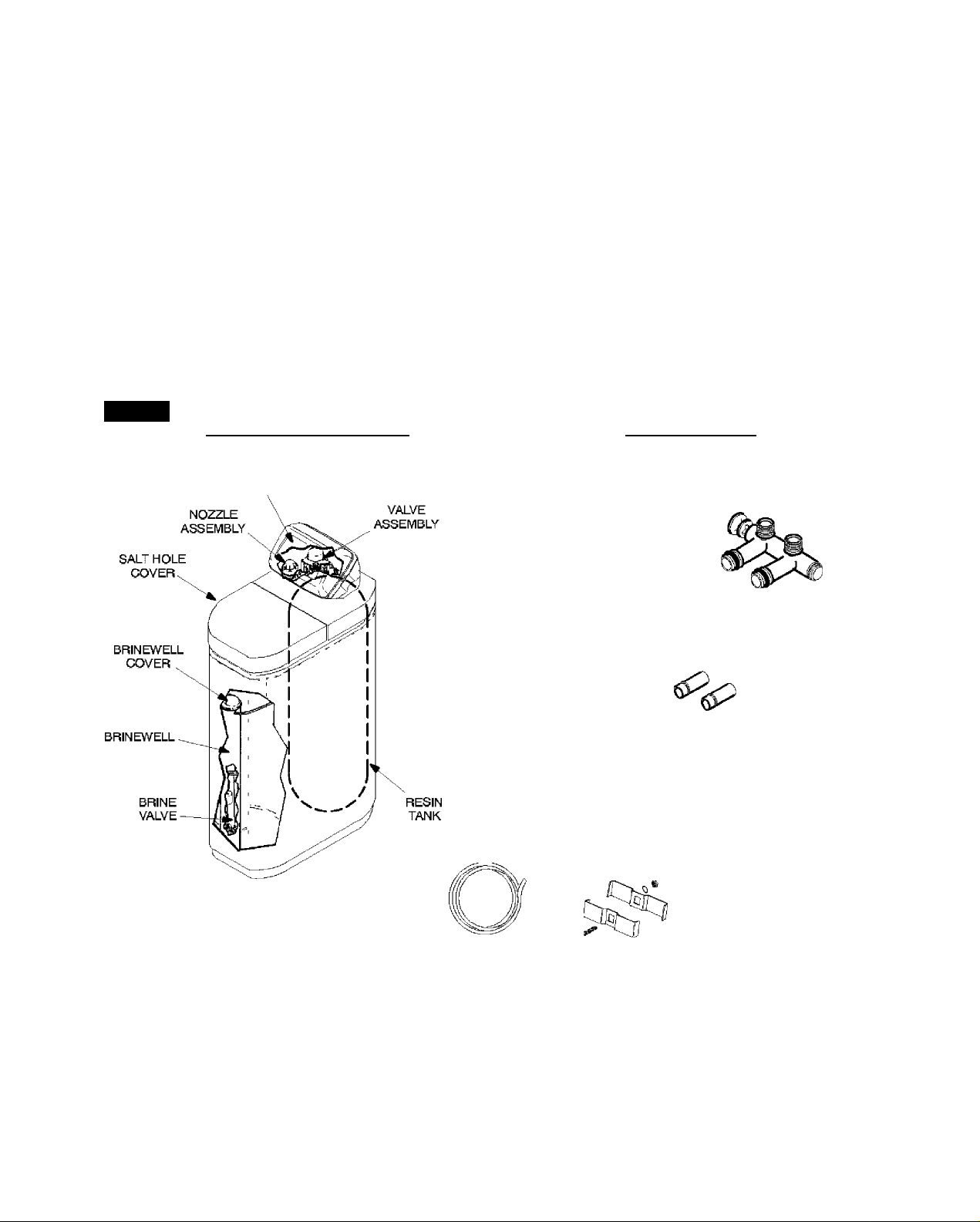
FIG. 1
PARTS DESCRIPTIONS SMALL PARTS
FACE
PLATE
I
Use care when handling the softener. DO NOT turn
upside-down. DO NOT drop, or set on sharp objects
that could make a hole in the bottom. The water soft
ener is heavy and to avoid damage, or personal inju
ry, do not try to lift it or move more than necessary.
See page 3-4, when you are ready to move it into
installation position.
in<;
installation manual
n
owner’s manual
tubes (2)
gaskets (2)
drain hose ground clamp kit
bypass valve
(included with some models)
copper
adaptor
tube
installation
nut (2)
tube
clamp (2)
grommet
1-2 Deluxe Valve
Problems, Questions? Call 1-800-426-9345 Kenmore Water Line
Page 6

Ls j j j j j j:
SECTION 1
ij jj:^.i.i j jj:^.^ ■ ■
C. WATER SYSTEM TESTS
BEFORE INSTALLING CHECKS & TESTS
Has your water supply had a chemical analysis?
Please see page A on the inside of the front cover.
CHECK YOUR WATER PRESSURE — For your
softener to work right, a water pressure of no lower
than 20 pounds per square inch (psi) is needed in the
house water pipes. The highest pressure allowed in
the water pipes is 125 psi. If pressure is over 125 psi,
buy and install a pressure reducing valve in the wa
ter inlet pipe to the softener.
Note:
If water pressure during the day is 100 psi or more,
pressure during the night may go over 125 psi. Ad
ding a pressure reducing valve may reduce the flow.
If you have a well water system, look at the pressure
gauge to find the water pressure. Call your local wa
ter department if you have city water. They will teU
you what the water pressure is where you live.
CHECK YOUR WATER FLOW RATE — A water
flow of at least 3 gallons per minute is needed. A
lower flow will keep your softener from working as
well as it should. To make an easy check of your flow
rate, do the following. You will need a one gallon
container (can, jar, pail, etc.).
FuUy open two cold water faucets dose to the
point water enters the house.
With both faucets open, fill the gallon container
at one faucet while looking at a watch or clock to
see how many seconds it takes.
Empty the container and go to the second faucet
(be sure BOTH faucets are still on). Fill the gallon
container at the second faucet and see how
many seconds it takes.
Turn off both faucets. Now add the number of
seconds it took to fill the container at both fau
cets.
A total of 90 seconds, or less, means the system
flow rate is good.
FOR future reference, ENTER RESULTS OF YOUR WATER SYSTEM TESTS IN THE
"FACTS AND FIGURES TO KEEP" TABLE IN YOUR OWNERS MANUAL.
1-3 Deluxe Valve
Problems, Questions? Call 1-800-426-9345 Kenmore Water Line
Page 7

Ls jj:^.i.i j jj:^.i.i j jj:^.i.i j jj:^.i.i j jj:”
SECTION 2
A. WHERE TO INSTALL THE WATER SOFTENER
Ls jj:^.i.i j jj:^.i.i j jj:^.i.i j jj:^.i.i j jj:.
PLAN YOUR INSTALLATION
c
T
o
N
Think of the following points as
you choose a place to put your
softener, (see FIG. 2).
• Place as close as possible to the
pressure tank (well water) or
water meter (city water).
• Place as close as possible to a
water drain such as a floor
drain, laundry tub, sump or
standpipe.
Connect to the house main wa
ter pipe BEFORE THE WATER
HEATER. Temperature of wa
ter going through the softener
must not be more than 120°F
(49°C). Hot water will damage
inner softener parts. To reduce
the risk of hot water backup, pip
ing between the softener and
water heater should be as long
of a run as possible.
Keep outside faucets on hard
water to save soft water and
salt.
Do not install in a place where the softener could
freeze. Damage caused by freezing voids the
warranty by Sears, Roebuck and Co.
Put the softener in a place water damage is least
likely to occur if it develops a leak. Sears or the
manufacturer will not repair or pay for water
damage.
A grounded, 120V electrical outlet, to plug the
transformer into is needed within 10 feet of the
softener (the softener has a 10 foot power cable).
Be sure the outlet and transformer are in an in
side place, to protect from wet weather. So the
softener always has electrical power, use a con
tinuously "live" outlet, that cannot be accidental
ly switched off.
When installing in an outside location, you must
take the steps necessary to assure the softener,
installation plumbing, and wiring, are as well
protected from the elements, contamination,
vandalism, etc., as when installed indoors.
Keep the softener out of direct sunlight. The
sun's heat can melt plastic parts.
FIG. 2
THE PROPER ORDER TO INSTALL WATER TREATING EQUIPMENT
(Shows sequence of equipment only. — Seldom, if ever, would all items be needed*.)
Page 8

Ls jj:^.i.i j jj:^.i.i j jj:^.i.i j jj:^.i.i j jj:”
B. TOOLS, PIPE AND FITTINGS, OTHER MATERIALS NEEDED
SECTION 2
Ls jj:^.i.i j jj:^.i.i j jj:^.i.i j jj:^.i.i j jj:.
PLAN YOUR INSTALLATION
You must first decide how to run in and out pipes to
the softener. Look at your house main water pipe at
the point you will connect the softener. Is the pipe
soldered copper, glued plastic, or threaded galva
nized or brass? What is the pipe size? What kind of
pipe and fittings is it easiest for you to work with,
and what tools do you have?
Now look at the common plans for in and out piping
on page 2-4 (soldered copper) and 2-5 (threaded).
Select the drawing best for you and use it as a guide
to plan what materials you will need. As you plan
your in and out piping, keep in mind the following
check list. Then get all the materials you will need
before you start.
Notes:
Use page 2- 3 to make a plan drawing for your spe
cific installation.
Some models include a plastic bypass valve, a
length of valve drain garden hose, and a length of
overflow drain hose for the salt storage tank.
In and out fittings included with the softener are 3/4 "
(nominal) copper sweat tubes. You should maintain
the same, or larger, pipe size as the water supply
pipe, up to the softener inlet and outlet.
Use copper, brass, galvanized or CP VC plastic
pipe and fittings for the in and out pipes. Be sure
to check local codes.
y If you do plumb with threaded or CPVC in and
out pipes, buy the needed adaptors and solder to
the inlet and outlet copper tubes provided.
ALWAYS install a bypass valve or valves. Either
use the Sears special valve (included with some
models and available at your local Sears store), or
3 shut-off valves (see pages 2-4 and 3-3). Bypass
valves let you turn off water to the softener if
needed for repairs, but still have water in the
house pipes.
Drain tubing (3/8 in. inside diameter), is needed
for the valve and salt tank drains. See step 1 and
2 on page 3-5 and 3-6. Some models include a
length of drain tubing, or you can buy tubing at
most Sears stores.
If a rigid valve drain is needed to comply with
plumbing codes, you can buy the parts needed (see
page 3-5) to change the softener to a 1/2 in. mini
mum copper tubing drain.
TOOLS NEEDED;—Common and cross point
(Phillips) screw drivers, slip joint pliers and a
tape measure or rule. ALSO...
...for SOLDERED COPPER — tubing cutter, pro
pane torch, solid-core LEAD-FREE solder, paste
flux, emery cloth, sandpaper or steel wool.
£qj. threaded pipe — hacksaw or pipe cutter,
pipe wrenches, pipe threading tool, pipe Joint com
pound approved for use on potable water.
...for CPVC PLASTIC — hacksaw, adjustable
wrench, solvent cement approved for use on pota
ble water, primer.
Copper and galvanized pipe corrode fast when
connected together. Use pipe and fittings of the
same material.
2-2 Deluxe Valve
Problems, Questions? Call 1-800-426-9345 Kenmore Water Line
Page 9

Ls jj:^.ì.ì j jj:^.ì.ì j jj:^.ì.ì j jj:^.ì.ì j jj:”
FIG. 3
SECTION 2
Ls jj:^.ì.ì j jj:^.ì.ì j jj:^.ì.ì j jj:^.ì.ì j jj:.
PLAN YOUR INSTALLATION
B. PIPE AND FITTINGS, PLAN DRAWING
jSHgjSigE WIN m-n=n
LEFT
120V - 60Hz
Electrical
Outlet
VALVE
Ot/TLET SIDE
RIGHT
* In what direction does the
water fiow? Be sure to plan
IN and OUT piping so water
flow is to the softener valve
inlet. Plan a crossover if
Draw the plans for your In and OUT piping
here. Be sure to follow the guides on page
2-2. Include all pipe, fittings and accesso
ries you will use. Make a list of all materials
you will need and buy them before
begin to install the water softener.
you
2-3 Deluxe Valve
Problems, Questions? Call 1-800-426-9345 Kenmore Water Line
Page 10

Ls jj:^.ì.ì j jj:^.ì.ì j jj:^.ì.ì j jj:^.ì.ì j jj:”
C. TYPICAL SOLDERED COPPER (OR CPVC) IN AND OUT PIPES TO SOFTENER
SECTION 2
Ls jj:^.ì.ì j jj:^.ì.ì j jj:^.ì.ì j jj:^.ì.ì j jj:.
PLAN YOUR INSTALLATION
FIG. 4
DELUXE VALVE MODELS
OUT
f’ NPTX
Sweat
Reducer (2)
Outlet
IN
t
\
r NPT
VALVE
SOFTENER
*NOTE:
For 1 in. plumbing connection, buy 2 sweat
adaptors (1 in. female thread x 1 in. sweat) and
plumb directly to the inlet-outlet adaptors or by
pass valve. Threads on the inlet-outlet adaptors
and bypass valve are 1 in. pipe thread.
CAUTION:
DO ALL SOLDERING BEFORE CONNECT
ING SWEAT ADAPTOR TO INLET-OUTLET
ADAPTORS OR BYPASS VALVE.
2-4 Deluxe Valve
Problems, Questions? Call 1-800-426-9345 Kenmore Water Line
Page 11

Ls jj:^.ì.ì j jj:^.ì.ì j jj:^.ì.ì j jj:^.ì.ì j jj:”
D. TYPICAL THREADED IN AND OUT PIPES TO SOFTENER
SECTION 2
Ls jj:^.ì.ì j jj:^.ì.ì j jj:^.ì.ì j jj:^.ì.ì j jj:.
PLAN YOUR INSTALLATION
FIG. 5
If you are planning a threaded plumbing installation, with a 3-valve bypass, use the
drawing in Fig. 4 as a guide. Use union fittings, as needed, to connect the plumbing.
DELUXE VALVE MODELS
Outside
Faucets
FITTINGS
REQUIRED NOT
IDENTIFIED
90* Elbow (2)
Union (2)
Pipe (as reg.)
Outlet
SOFTENER
OUT
NOTE:
It may be easier to slip the pressure fit ground
clamps onto the plumbing prior to making all
connections permanent. See page3-8.
1 " X 3/4" reducer'
VALVE
*NOTE:
For 1 in. plumbing connection,
usea1 in. threaded straight connec
tor.
2-5 Deluxe Valve
Problems, Questions? Call 1-800-426-9345 Kenmore Water Line
Page 12

SECTION 3
A. ASSEMBLE INLET-OUTLET ADAPTORS, OR PLASTIC BYPASS VALVE
Close the shut-off valve on
the house main water pipe,
near the water meter or pres
sure tank, to turn off the wa
ter.
c
Shut off the gas or electric
T
o
supply to the water heater.
Open the highest and lowest
water faucets in your house to
let water drain from the pipes.
Close faucets after water has
drained.
N
If not already done, remove
all cardboard or plastic pack
ing pieces from inside the
softener. Set the parts bag
where you can easily see it,
and get to parts as you need
them.
!
! JJJJiJ
:JJ/ '
i J.J.,
:
i
JJJJJJ
JJJJJJ
~T J JJJJ
JJJJJ
jjjj^
ÍJJJJ J
JJJJJ
JJJJJ
JJJJJ
STEP BY STEP GUIDES TO INSTALL
M INSTALL SEARS BYPASS VALVE AND / OR
THE INLET OUTLET COPPER TUBES (FIG.
4, 5 AND 6). AH needed parts are in the parts
bag.
Note:
If you will not install the bypass valve because you
win have a 3-valve bypass, skip step b, but do steps
a and c.
e Visually check and remove any foreign materi
als from the valve inlet and outlet ports (FIG. 6).
Carefully remove the two large plastic clips (you
will use them). Check to be sure the turbine and
turbine support are firmly in place. (Fig. 6)
^ BYPASS VALVE: If not already done, put a hght
coating of silicone grease on the o-ring seals and
slide onto the bypass valve. Push the bypass
valve into the softener valve as far as it wifi go.
Snap the 2 large holding clips into place, from
the top down as shown. (Fig. 7)
CAUTION...Be sure the clips snap firmly
into place so the bypass valve will not pull out.
(Fig- 7)
GO TO PAGE 3-4.
INLET AND OUTLET COPPER TUBES: If not
already done, put a light coating of silicone
grease on the o-ring seals and slide onto the cop
per tubes. Place the tubes into the valve inlet and
outlet ports, or bypass valve ports, as far as they
win go. Both tubes are the same and fit either
port. Tighten the installation nuts holding the
copper tubes. (Fig. 7)
CAUTION.. .Be sure the clips snap firmly
into place so the tubes will not pull out. (Fig. 7)
GO TO PAGE 3-3.
3-1 Deluxe Valve
Problems, Questions? Call 1-800-426-9345 Kenmore Water Line
Page 13

Ls j j:^.í.¿ j j j:^.í.¿ j j j:^.í.¿!
SECTION 3
STEP BY STEP GUIDES TO INSTALL
A. ASSEMBLE INLET-OUTLET ADAPTORS, OR PLASTIC BYPASS VALVE
DELUXE VALVE MODELS
FiG.6
INSTALLING BYPASS VALVE, and / or
INLET and OUTLET COPPER TUBES
FIG.7
INSTALLING HOLDING CLIPS
black cross section of
FIG.8
BYPASS VALVE TURNED
DOWNWARD
TURN BYPASS VALVE
UPSIDE DOWN TO
CONNECT TO FLOOR
LEVEL PLUMBING
3-2 Deluxe Valve
Problems, Questions? Call 1-800-426-9345 Kenmore Water Line
Page 14

Ls j j:^.ì.ì j j j:^.ì.ì j j j:^.ì.ì!
SECTION 3
STEP BY STEP GUIDES TO INSTALL
B. INSTALL 3-VALVE BYPASS
INSTALLING 3 VALVE BYPASS AND PIPES
(FIG. 9)
0 Cut the house main water pipe where you will
connect the softener. Loosely put together pipe,
fittings, and the 3 valves. Place valve(s) within
easy reach.
F1G.9
3 - VALVE BYPASS
(threaded plumbing shown)
IMPORTANT:
When looking at the front of the softener, the inlet
is on the right side. If water in your house main wa
ter pipe runs from left to right, be sure to use a
"cross-over" as shown on page 2-3.
When all pipe, fittings and valves make a good
fit together, tighten all threaded joints (use joint
compound on outside threads), or solder all
sweat joints.
to softener
inlet
3-3 Deluxe Valve
Problems, Questions? Call 1-800-426-9345 Kenmore Water Line
Page 15

J J J J J J
SECTION 3
J jj:^.i.i J jj:^.^ ■ ■
STEP BY STEP GUIDES TO INSTALL
C. LOCATE WATER SOFTENER, AND CONNECT PIPES
MOVE THE SOFTENER INTO PLACE
Move the softener into place, onto a level and
smooth surface. If needed, put a piece of 3/4"
plywood, at least 17" x 20", under the tank. Then
put spacers under the plywood to level the soft
ener. Do not put shims or spacers directly under
the tank, without the plywood. The weight of
the softener, when full of salt and water, may
cause the tank to puncture or break at the shim
or spacer.
To move the softener, grip under the ridge on the
salt tank sidewall and carefully rock back and forth,
into position.
CONNECT THE SOFTENER (Refer to your
plan drawing on page 2-3, and to page 2-4 or
2-5. Read the IMPORTANT note on page 3-3.
Then, measure, cut (thread if needed) and put all
pipe and fittings together up to the main water
pipe, or to the bypass valve(s) you installed on
page 3-3.
FiG.10
FiG.11
MOVE SOFTENER INTO PLACE
i
plywood
shims
TYPICAL SOLDERING
CONNECTIONS
Notes:
■ Include adaptors, reducers, union fittings, etc., as
needed.
■ Cut pipe lengths exact for correct aligning, and to
prevent stress on the softener valve.
■ Use pipe joint compound or Teflon tape on out
side pipe threads.
■ When ail piping fits together...
...solder all sweat fittings.
...prime and cement ail CPVC joints.
.. .tighten all threaded joints.
® CAUTIONS:
Jhi^ Never solder fittings while connected to non
metallic parts. Wait until soldered pipe has cooled
before connection (see fig. 11).
Be careful when putting pipe fittings together.
Do not cross thread, and do not overtighten.
4. Solder
NOTE: To be certain heat
will not travel down the pipe
and into the trypass valve
(or installation adaptors),
wrap the bottom of the pipe
and the bypass valve in a
wet rag.
. Cut pipe to
X correct length.
2. Solder (WHEN
/ COOL, do Step
3).
CAREFULLY,
turn onto bypass
valve and
tighten (use pipe
joint compound
or Teflon tape).
3-4 Deluxe Valve
Problems, Questions? Call 1-800-426-9345 Kenmore Water Line
Page 16

SECTION 3
D. CONNECT VALVE AND SALT TANK DRAINS
__
CONNECT THE VALVE DRAIN HOSE
Take a length of 3 / 8" inside diameter drain tub
ing and attach one end to the drain fitting (FIG.
12). Use a tube clamp to hold it in place. Put the
other end of the tubing over a floor drain, into a
laundry tub, standpipe, or other suitable drain.
Check your local codes.
Leave an air gap of about 1-1/2" between the end
of the hose and the drain. This gap is needed so you
don't get a back-flow of sewer water into the soften
er. Do not put the end of the hose into the drain or
connect without the air gap.
Jh^ Place and support the hose so it does not kink or
have sharp bends. So water pressure does not cause
the hose to "whip", tie or wire it in place. Do not
pinch the hose shut. The softener will not work if
this drain hose is pinched, plugged, closed or re
stricted in any way.
STEP BY STEP GUIDES TO INSTALL
A Keep the hose lower than the drain fitting, (In
some homes, to get to a drain you must raise the
hose and run it over-head. If you need an overhead
drain, do not raise the hose more than 8' above the
floor. A copper drain tube is best to use.)
COPPER DRAIN TUBE: The plumbing codes
where you live may say that you must use a copper
valve drain tube. A copper tube is also best to use for
an over-head drain. Use a copper drain tube if the
softener is installed outside, or in the sunlight. Heat
from the sun makes many kinds of rubber or plastic
hose to soften, flatten and close up.
To adapt a copper drain tube to the softener, buy a
compression fitting (1/4 in. female pipe threads x
1/2 in. O.D. tube) and tubing from your local hard
ware store.
FIG.12
DELUXE VALVE
FIG.13
3-5 Deluxe Valve
Problems, Questions? Call 1-800-426-9345 Kenmore Water Line
Page 17

Ls j j:^.ì.ì j j j:^.ì.ì j j j:^.ì.ì!
SECTION 3
D. CONNECT VALVE AND SALT TANK DRAINS
STEP BY STEP GUIDES TO INSTALL
CONNECT SALT TANK OVERFLOW TU
BING
Take the rubber grommet, tube adaptor and
tube damp (FIG. 12) that are in the parts bag.
o Push the grommet into the hole in the salt tank
wall so half is inside and half is outside.
e Push the bigger end of the tube adaptor into the
grommet.
Push one end of a length of 3 / 8'T.D. tubing onto
the tube adaptor, using the tube clamp to hold
it in place. Put the other end of the tubing over
the floor drain.
Important:
• The salt tank overflow is for safety only. If the
salt tank should overfill with water, the over
flow tubing carries it to the drain.
• Over-flu water must run downward through
the tubing. Do not raise the tubing higher than
the grommet and tube adaptor (FIG. 12).
• Do not connect to the valve drain hose you
installed in step 1. Both drains must have a sepa
rate hose or tube.
3-6 Deluxe Valve
Problems, Questions? Call 1-800-426-9345 Kenmore Water Line
Page 18

J J J J J J
SECTION 3
E. PRESSURE TEST / CHECK FOR LEAKS
J jj:^.i.i J jj:^.^ ■ ■
STEP BY STEP GUIDES TO INSTALL
CAUTION:
To avoid water or air pressure damage to soft
ener inner parts, and to flush pipe chips or
other residue from the water pipes, be sure to
do the following steps exactly as instructed.
Look at the picture in FIG. 15 showing your kind of
bypass valve(s).
Fully open two cold, soft water faucets nearby
the softener.
Place bypass valve(s) in "bypass" position. On
a single valve, slide the stem inward to bypass.
On a 3-valve system, close the inlet and outlet
valves and open the bypass valve.
Fully open the house main water pipe shutoff
valve (closed in step 1, page 3-1). Observe
steady water flow from both open faucets.
Place bypass valve(s) in ‘'service". EXACTLY as
follows: Keep soft water faucets open.
FiG.14
HOUSE MAIN WATER
SHUTOFF VALVES
FiG.15
Bypass va!ve(s) should always remain in soft
water service position. Position in bypass only
if needed for softener repairs.
SINGLE BYPASS
PULL STEM
OUTWARD
FOR
SERVICE
SINGLE BYPASS VALVE: SLOWLY, sHde pull
the valve stem outward toward service, pausing
several times to allow the softener to pressurize
slowly.
3-VALVE BYPASS: Fully close the bypass valve
o
and open the outlet valve. SLOWLY, open the
inlet valve, pausing several times to allow the
softener to pressurize slowly.
After about three minutes, open a hot water
faucet for about one minute, or until all air is
expelled, then close.
Close both cold water faucets.
Check your plumbing work for leaks and fix
right away if any are found. Be sure to observe
previous caution notes.
Push
Inward
For
Bypass
3 - VALVE BYPASS
FOR SERVICE
close bypass valve
open Inlet & outlet valves
FOR BYPASS
open bypass valve
close Inlet & outlet valves
3-7 Deluxe Valve
Problems, Questions? Call 1-800-426-9345 Kenmore Water Line
Page 19

Ls j j j j j
SECTION 3
j jj:^.i.i j jj:^.^ ■ ■
STEP BY STEP GUIDES TO INSTALL
F. GROUNDING / CONNECT TO ELECTRICAL POWER
INSTALL GROUNDING WIRE BETWEEN
THE SOFTENER IN AND OUT PIPES
The house cold water pipe (iron or copper) is
often used to ground all electrical outlets in the
home. Outlets are grounded to protect you from
shock when you touch any electric appliance
plugged into the outlet. If you installed the
single bypass valve (FIG. 15), the cold water
pipe ground is broken.
FIG.16
COLD WATER PIPE GROUNDING
To restore the ground, take the ground clamp kit
that is on the cardboard liner. Install across the inlet
and outlet copper tubes as shown in FIG. 16. Be sure
good contact is made between the pipe and the
clamps.
FIG.17
WATER METER JUMPER WIRE
Important:
Be sure the cold water pipe has direct metal to metal
contact aU the way to the ground. Plastic, rubber or
other electrically insulating parts such as hoses, fit
ELECTRICAL POWER OUTLET FOR YOUR
SOFTENER
The softener works on 24 volt, 60 Hz electric
power. The included transformer changes stan
dard 120 volt AC house power to 24 volts. You
must plug the transformer into a grounded, 120
volt outlet only. Be sure the outlet is always
"live" so someone cannot turn it off by mistake.
tings, washers or gaskets can break the direct metal
to metal contact. Also check the water meter (city
water) or the well pump. Install #4 copper jumper
wires, clamped tightly on both ends, across insu
lated parts (FIG. 17).
Note:
The included transformer is made for inside use only.
Be sure the electrical outlet you plug the transform
er into is inside, to protect from weather (see page
-1).
2
3-8 Deluxe Valve
Problems, Questions? Call 1-800-426-9345 Kenmore Water Line
Page 20

SECTION 3
F. GROUNDING / CONNECT TO ELECTRICAL POWER
j jj:^.i.i j jj:^.^ ■ ■
STEP BY STEP GUIDES TO INSTALL
PLUG IN THE TRANSFORMER
Plug the transformer into the electrical outlet.
FIG. 18
After installing your water softener, replace the cov
ers. For the UltraSoft 100, first position the main
cover on the softener. Then, set the salt hole cover
into the main cover, and lower closed. For the UltraSoft 200, angle the covers so the main cover clips
onto the back first, then bring down in front and clip
on the 2 tabs inside the rim of the salt hole and lower
the salt cover closed.
CONNECTING TRANSFORMER
RESTART THE WATER HEATER
TURN ON THE GAS (OR ELECTRIC) SUPPLY TO THE WATER HEATER AND LIGFIT THE PILOT
Your new Sears softener is now softening the water
for your household needs. However, your WATER
HEATER is filled with hard water. To have fully
soft water right away, you can drain the water heat
er so it refills with soft water. If you don't drain the
water heater, it will take a few days before you have
fully soft water.
YOUR PLUMBING AND ELECTRICAL WORK IS COMPLETE.
To drain the water heater, open a hot water faucet
and let it run until the water runs cold. Then close
the faucet.
Now go to your owner's manual and do the softener start-up sieps...setting the timer, adding
salt to the storage tank, sanitizing, etc.
3-9 Deluxe Valve
Problems, Questions? Call 1-800-426-9345 Kenmore Water Line
 Loading...