

Page 1
OWNER'S
MANUAL
MODEL NO.
UltraFilter 300
625.384720
UltraFilter 500
625.384750
Caution:
Read and Follow
All Safety Rules and
Operating Instructions
Before First Use of
This Product.
If you have questions when
installing, operating or
maintaining your reverse
osmosis system, call this
toll-free number...
1-800-426-9345
www.KenmoreWater.com
Reverse Osmosis
Drinking Water System
• Warranty
• How To Install
• How It Works
• Care Of
• Repair Parts
System tested and certified by NSF International
to ANSI/NSF Standard 58 for the reduction of the
claims specified on the performance data sheet.
SAVE THIS MANUAL
PRINTE_ IN U._J_.
Sears, Roebuck and Co., Hoffman Estates, IL 60179 U. S. A.
Part No. 7227352 (Rev. L 10/21/03)
Page 2
- WARRANTY-
_ t t t t t t t t t t t t t t t t t t t t t t t t t t t t t _
I I
I (except filter cartridges and R. O. membrane) t
I For one year from the date of purchase, when the Reverse Osmosis Drinking Water System is installed I
and maintained in accordance with our instructions, Sears will repair, free of charge, defects in material
t and workmanship, except filter cartridges and the R. O. membrane, t
! !
I TO OBTAIN WARRANTY SERVICE, SIMPLY CONTACT THE NEAREST SEARS SERVICE CENTER
THROUGHOUT THE UNITED STATES. This warranty applies only while this product is in use in the
t United States. t
! !
I Thiswarrantygivesy_uspecific_ega_rights_andy_umayhave_therrightswhichvaryfr_mstatet_state_ I
! !
t Sears, Roebuck and Co., D/817 WA, Hoffman Estates, IL 60179 !
FULL WARRANTY ON REVERSE OSMOSIS DRINKING WATER SYSTEM
I_ ............................. J
SEARS INSTALLATION POLICY
All installation labor arranged by Sears shall be per-
formed in a neat, workmanlike manner in accor-
dance with generally accepted trade practices. Fur-
ther, all installations shall comply with all local laws,
codes, regulations, and ordinances. Customer shall
also be protected during installation by insurance re-
lating to Property Damage, Workman's Compensa-
tion and Public Liability.
installation prove faulty within one year, Sears will,
SEARS INSTALLATION WARRANTY
In addition to any warranty extended to you on the
Sears merchandise involved, which warranty be-
comes effective the date the merchandise is installed,
should the workmanship of any Sears arranged
upon notice from you, cause such faults to be cor-
rected at no additional cost to you.
I
I
- SAFETY GUIDES -
• Read all steps and guides carefully before instal-
ling and using your reverse osmosis system. Follow
all steps exactly to correctly install. Reading this
manual will also help you to get all the benefits from
the reverse osmosis system.
• Do not attempt to use this product to make safe
drinking water from non-potable water sources. Do
not use the system on microbiologically unsafe wa-
ter, or water of unknown quality without adequate
disinfection before or after the system. This system
is certified for cyst reduction and may be used on
disinfected water that may contain filterable cysts.
• Check with your local public works department
for plumbing and sanitation codes. You must fol-
low their guides as you install the system. Follow
your local codes if they differ with guides in this
manual.
• This system shall only be used for arsenic reduc-
tion on chlorinated water supplies containing de-
tectable residual free chlorine at the system inlet.
Water systems using an inline chlorinator should
provide a one minute chlorine contact time before
the RO system.
Problems, Questions? Call 1-800-426-9345 Kenmore Water Line
• This system is acceptable for treatment of influ-
ent concentrations of no more than 27 mg/L nitrate
and 3 mg/L nitrite in combination measured as N
and is certified for nitrate/nitrite reduction only for
water supplies with a pressure of 280 kPa (40 psig)
or greater.
• The reverse osmosis system works on water pres-
sures of 40 psi (minimum) to 100 psi (maximum). If
your house water pressure is over the maximum,
install a pressure reducing valve in the water supply
pipe to the reverse osmosis system.
Do not install the reverse osmosis system out-
side, or in extreme hot or cold temperatures. Temper-
ature of the water supply to the reverse osmosis sys-
tem must be between 40°F and 100°F. Do not install
on hot water.
Read the other limits (pH, hardness, etc.) in the
specifications and be sure your water supply con-
forms. Also see "Water Supply" on page 3.
The reverse osmosis membrane contains a pre-
servative for storage and shipment. Be sure to purge
as instructed on page 9 before using product water.
2
Page 3
- TABLE OF CONTENTS -
Where To Install the RO System ........ 4
Tools and Materials Needed ........... 4
Installation Steps .................... 5- 9
Cold Water Supply .................. 5
Drain Adapter ..................... 6
Faucet ............................ 6- 7
RO Assembly ...................... 7
Storage Tank, Tubing Connections .... 8
Installation Steps - continued
Sanitizing, Pressure Test, Purging .... 9
How the RO System Works ........... 10-11
Care of RO System ................... 12-15
Dimensions, Specifications ............ 16
Remote Installation Locations ......... 17
Repair Parts ......................... 18-19
- WHAT YOUR REVERSE OSMOSIS SYSTEM WILL DO -
Your Reverse Osmosis (RO) Drinking Water System
is a water treatment unit. It uses household water
pressure to reverse a natural physical process called
osmosis. Water, under pressure, is forced through a
semi-permeable membrane where minerals and im-
purities are filtered out. Clean drinking water goes to
the faucet or storage, while minerals and impurities
are sent to the drain with RO waste water. The miner-
als and impurities are measured in water as total dis-
solved solids (TDS).
The system includes replaceable pre and postfilter
sediment-carbon cartridges. The prefilter removes
sand, silt, dirt, rust particles, other sediments, and
chlorine from the water supply before it can enter the
RO membrane. The postfilter removes any tastes
and/or odors that may remain in the water, after
passing through the RO membrane, and just before
going to the RO faucet. To prevent water waste, an
automatic shutoff valve doses when the RO faucet is
closed and the storage tank is full.
Your reverse osmosis system gives you a continuous
supply of sparkling clear, delicious water for drink-
ing, cooking and other uses. Foods will look and
taste better too. Having high quality RO product wa-
ter at your fingertips eliminates the need to buy
bottled water. The storage tank holds over 2 gallons
of RO product water for your needs.
- BEFORE YOU BEGIN TO INSTALL THE RO SYSTEM -
FOR OPTIMUM PERFORMANCE YOUR KEN-
MORE REVERSE OSMOSIS SYSTEM SHOULD BE
INSTALLED ON SOFTENED WATER.
CAUTION: A refrigerator icemaker may not operate
properly when connected to a reverse osmosis sys-
tem that has been installed on a water system that op-
erates outside of the specified pressures listed on
page 16.
Check Your Water Supply: The cold water supply to
the RO system must be within certain quality limits.
See the specification table on page 16. If supply water
is not within limits, the RO system can not make
product water as it should and reduced RO mem-
brane life will result.
Trained sales people at Sears can arrange for a free
water analysis. The analysis will tell you if other wa-
ter supply treatment is needed before going to the
RO system.
CAUTION: Chlorine in the water will destroy the
RO membrane. Most cities add chlorine to the wa-
ter supply to kill bacteria. The prefilter removes
chlorine up to the limits shown in the specifications
before it enters the RO membrane. It is important
Problems, Questions? Call 1-800-426-9345 Kenmore Water Line
to replace the prefilter cartridge at least every 6
months. See the RO care guide on page 16.
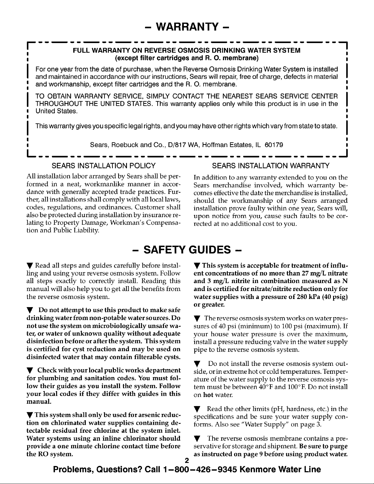
Check Parts Included: Unpack the carton and re-
move the RO system. In addition to the assembled
RO and the storage tank, the system includes the
parts illustrated below, a separate length of tubing,
and this manual.
FIG. 1 HANGERWASHERS WATERFAUCET
&SCREWS
©
TEFLON
TAPE
[3 DRAIN
r_, _PTER
TUBING
ADAPTER
WATER SUPPLY
FITTING
1
L
3
AA BATTERIES
(MONITOR
MODEL)
ROPRODUCT
Page 4
- WHERE TO INSTALL THE RO SYSTEM -
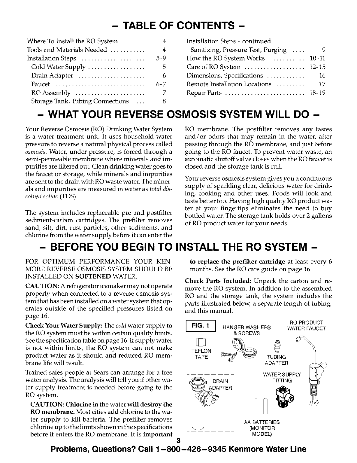
The RO assembly and storage tank is designed for
installation under the sink, usually in the kitchen or
bathroom. The RO assembly mounts on a wall sur-
face, or can lay on the cabinet floor next to the storage
tank. Hanger washers and wood screws are included
for cabinet wall mounting. The RO product water
faucet installs on the sink, or on the countertop next
to the sink (pages 6 and 7).
Note: Tubing lengths allow for the removal of the
assembly from the hanger washers for servicing. If
tubing lengths are shortened for neater appear-
ance, it may be necessary to keep the assembly on
the hanger washers for service.
You can also locate the RO assembly and storage tank
FIG. 2 ]
in any remote location from the faucet, observing
safety guides on page 2. You do need a nearby water
source and drain point (see page 17).
Water Supply: To provide supply water to the RO
system inlet use the included feed supply fitting or
install pipe fittings for tubing connection, as typical-
ly shown on page 5.
Drain Point: A suitable drain point is needed for re-
ject water from the RO membrane. A floor drain,
laundry tub, standpipe, sump, etc., is preferred, as
shown in the remote locations drawing, page 17. A
sink p4rap drain adaptor is included to install where
codes permit, as an optional drain point (page 6).
RO prod ucl:
\ [_water faucet
sink drain RO Assembly
p-trap
- TOOLS AND MATERIALS NEEDED -
• adjustable wrench, standard pliers, and larger
adjustable jaw pliers or pipe wrench to fit sink drain
slotted and Phillips head screwdrivers
plumbers putty
- 6 STEPS TO INSTALL -
STEP 1: - Install Cold Water Supply fittings - page
5
STEP 2: - Install Drain Adapter - page 6
STEP 3: - Install Faucet - pages 6 and 7
adapter
• electric drill and bits, if hole is needed for the RO
faucet, page 6 and 7
STEP 4: - Install RO Assembly - page 7
STEP 5: - Install Storage Tank, Make Remaining Tub-
ing Connections - page 8
STEP 6: - Sanitizing, Pressure Testing, Purging -
page 9
4
Problems, Questions? Call 1-800-426-9345 Kenmore Water Line
Page 5
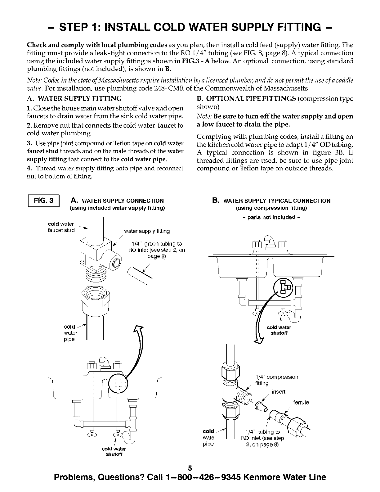
- STEP 1: INSTALL COLD WATER SUPPLY FITTING -
Check and comply with local plumbing codes as you plan, then install a cold feed (supply) water fitting. The
fitting must provide a leak-tight connection to the RO 1/4" tubing (see FIG. 8, page 8). A typical connection
using the included water supply fitting is shown in FIG.3 - A below. An optional connection, using standard
plumbing fittings (not included), is shown in B.
Note: Codes in the state of Massachusetts require installation by a licensed plumber, and do not permit the use of a saddle
valve. For installation, use plumbing code 248-CMR of the Commonwealth of Massachusetts.
A. WATER SUPPLY FITTING
1. Close the house main water shutoff valve and open
faucets to drain water from the sink cold water pipe.
2. Remove nut that connects the cold water faucet to
cold water plumbing.
3. Use pipe joint compound or Teflon tape on cold water
faucet stud threads and on the male threads of the water
supply fitting that connect to the cold water pipe.
4. Thread water supply fitting onto pipe and reconnect
nut to bottom of fitting.
B. OPTIONAL PIPE FITTINGS (compression type
shown)
Note: Be sure to turn off the water supply and open
a low faucet to drain the pipe.
Complying with plumbing codes, install a fitting on
the kitchen cold water pipe to adapt 1/4" OD tubing.
A typical connection is shown in figure 3B. If
threaded fittings are used, be sure to use pipe joint
compound or Teflon tape on outside threads.
"1
I FIG. 3 | A. WATER
J
cold water
faucet stud
cold
(using included water supply fitting)
SUPPLY CONNECTION
water supply fitting
/
lf4" green tubing to
RO inlet (see step 2, on
page 8)
B. WATER SUPPLY TYPICAL CONNECTION
(using compression fitting)
- parts not included -
1/4 compression
fitting insert
\
cold water
shutoff
cold
water
pipe
1/4" tubingto _._(_ "
RO inlet (see step
2, on page 8)
5
Problems, Questions? Call 1-800-426-9345 Kenmore Water Line
Page 6
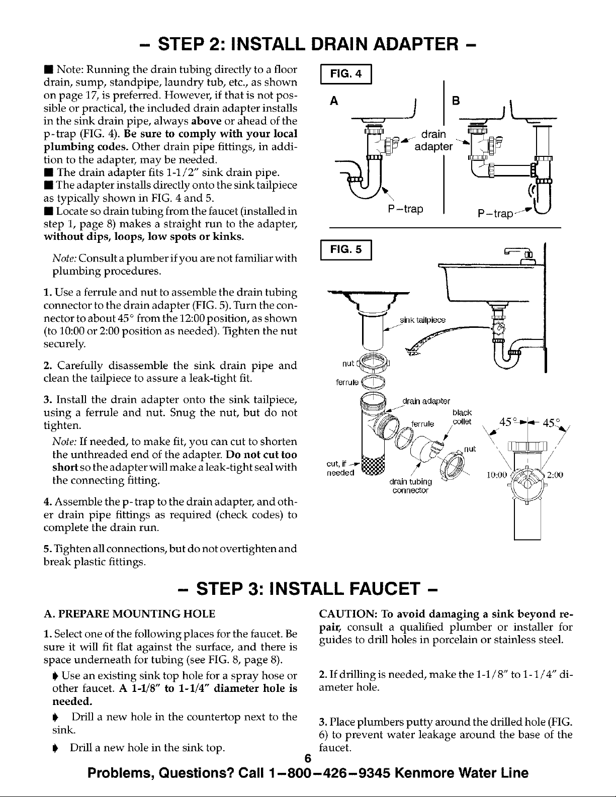
- STEP 2: INSTALL DRAIN ADAPTER -
• Note: Running the drain tubing directly to a floor
drain, sump, standpipe, laundry tub, etc., as shown
on page 17, is preferred. However, if that is not pos-
sible or practical, the included drain adapter installs
in the sink drain pipe, always above or ahead of the
p-trap (FIG. 4). Be sure to comply with your local
plumbing codes. Other drain pipe fittings, in addi-
tion to the adapter, may be needed.
• The drain adapter fits 1-1/2" sink drain pipe.
• The adapter installs directly onto the sink tailpiece
as typically shown in FIG. 4 and 5.
• Locate so drain tubing from the faucet (installed in
step 1, page 8) makes a straight run to the adapter,
without dips, loops, low spots or kinks.
Note: Consult a plumber if you are not familiar with
plumbing procedures.
1. Use a ferrule and nut to assemble the drain tubing
connector to the drain adapter (FIG. 5). Turn the con-
nector to about 45 ° from the 12:00 position, as shown
(to 10:00 or 2:00 position as needed). Tighten the nut
securely.
I FIG. 5 ]
i
F-1
2. Carefully disassemble the sink drain pipe and
clean the tailpiece to assure a leak-tight fit.
3. Install the drain adapter onto the sink tailpiece,
using a ferrule and nut. Snug the nut, but do not
tighten.
Note: If needed, to make fit, you can cut to shorten
the unthreaded end of the adapter. Do not cut too
short so the adapter will make a leak-tight seal with
the connecting fitting.
4. Assemble the p- trap to the drain adapter, and oth-
er drain pipe fittings as required (check codes) to
complete the drain run.
5. Tighten all connections, but do not overtighten and
break plastic fittings.
- STEP 3: INSTALL FAUCET -
A. PREPARE MOUNTING HOLE
1. Select one of the following places for the faucet. Be
sure it will fit flat against the surface, and there is
space underneath for tubing (see FIG. 8, page 8).
@Use an existing sink top hole for a spray hose or
other faucet. A 1-1/8" to 1-1/4" diameter hole is
needed.
f@lTul@ 0
drain adapter
bl_¢k
errule _llet
2:00
¢orlrlO_Or
CAUTION: To avoid damaging a sink beyond re-
pair, consult a qualified plumber or installer for
guides to drill holes in porcelain or stainless steel.
2. If drilling is needed, make the 1-1/8" to 1-1/4" di-
ameter hole.
@ Drill a new hole in the countertop next to the 3. Place plumbers putty around the drilled hole (FIG.
sink. 6) to prevent water leakage around the base of the
@ Drill a new hole in the sink top. faucet.
6
Problems, Questions? Call 1-800-426-9345 Kenmore Water Line
Page 7

- STEP 3: INSTALL FAUCET (cont.)-
..* SEM.LEF*UCET [FIG.6]
1. Remove the large blue nut from the faucet threads.
2. Slide the three attached tubes and the telephone
style wire (monitored models only) through the sink
or countertop hole, aligning gasket under faucet
base.
3. On the underside of the sink or countertop, screw
the nut on the faucet threads with the tubing and
wire running through the center hole of the nut.
Tighten the nut so the faucet cannot move, but do
not overtighten.
ASSEMBLED IN
MOUNTING HOLE
faucet & spout
gasket
/
4. CONNECT TUBING TO FAUCET AS FOLLOWS.
a. Using the 3/8" x 1/4" tubing adaptor, connect
the 1/4" blue tubing from the faucet to the 3/8" blue
tubing from the RO.
Note: See pages 13 and 14 for tubing connection in-
structions.
b. Using the 1/4" x 1/4" tubing adaptor, connect
the 1/4" red tubing from the faucet to the 1/4" red
tubing from the RO.
c. Monitored models only: Connect the telephone
style wire to the receptacle on PWA board in the RO
manifold and route the wiring through holes in top
cover and manifold assembly.
- STEP 4: INSTALL RO
ASSEMBLY -
hole in sink or_
countertop
318" black tubing
to drain point
telephone
style wire
\
tubing adapters-_o.,@
TUBING FROM
RO SYSTEM
FIG. 7 ] hoager
washer (2).
screw (2)__
plumbers putty
/
1/4" red
tubing
tubing
nut
114"red tubing
from RO drain
3/_" blue
tubing
7.2" (appr_ 7- 7/32")
Hang the assembly on the included hanger washers,
or lay on the cabinet floor, as desired.
1. Refer to FIG. 7 for wall mounting. Hold the assem-
bly up to the wall surface and mark locations for the
hanger washers. Distance needed is 7.2" (approx.
7-7/32") apart.
2. Install hanger washers at least 15-1/2" up from the
cabinet floor, allowing room to remove sumps from
filter heads. Wood screws are provided, or obtain
other fasteners as needed.
Problems, Questions? Call 1-800-426-9345 Kenmore Water Line
15-1/2 '_
rrlirl.
up from
floor
7
Page 8

- STEP 5: INSTALL STORAGE TANK,
MAKE REMAINING TUBING CONNECTIONS -
1. CONNECT DRAIN TUBING, FAUCET TO
DRAIN ADAPTER: Referring to FIG. 8, run the loose
section of black 3/8" tubing from the faucet to the
drain adapter, with a black collet, installed on page
6. Cut this tubing as needed to route in as straight of
a run as possible, without loops, dips, low spots or
kinks. Cut the end of the tubing square. Then push
all the way into the fitting. Pull on the tubing to be
sure it's held firmly in the adapter fitting. See pages
13 and 14 for tubing connection instructions.
2. CONNECT TUBING TO WATER SUPPLY: Con-
nect the feed (green) tube to the water supply fitting
installed on page 5. Connection to the fitting is as de-
TYPICAL UNDERSINK INSTALLATION
FIG. 8 ]
scribed in Fig. 11, page 14.
3. Move the storage tankinto place next to the RO as-
sembly. You can stand the tank upright, or lay it on
side. Apply no more than two wraps of Teflon tape
to the threads on the nipple at the top of the tank.
Hand tighten the other included tubing adapter fit-
ting with the yellow collet onto the tank nipple, then
wrench 1/4 turn only. BE CAREFUL NOT TO
CROSS THREAD.
4. Run the 3/8" yellow tubing to the fitting installed
in step 3. Be sure the end of the tubing is cut square,
and insert all the way into the fitting. Again, pull on
the tubing to be sure it's held firmly in the fitting.
RO prod ucl:
water faucet
water supply
fitting
HOT CeLD
tubing adapto_ yellow toilet
\
3/8" BLACK TUBING
Note: See note on page 4
drain
adap_r
""sink p-trap monitored models
regarding tubing lengths.
telephone cable
only
8
Problems, Questions? Call 1-800-426-9345 Kenmore Water Line
Page 9

- STEP 6: SANITIZING, PRESSURE TESTING & PURGING -
SANITIZING
Sanitizing is recommended upon installation of the
RO system, and after servicing inner parts. It is im-
portant for the service person to have clean hands
while handling inner parts of the system.
CAUTION: Be sure to remove the RO membrane
and both filter cartridges as follows, before sanitiz-
ing. Chlorine will destroy the RO membrane car-
tridge.
1. Be sure the water supply to the RO is turned off,
and the RO faucet is open to relieve pressure.
2. Referring to FIG. 9, page 12, remove the RO mem-
brane sump by twisting 1/4 turn left (_)). Remove
the RO cartridge from sump. Place the cartridge in
a clean plastic bag.
3. Be sure the o-ring sealis on the sump. Replace the
RO sump by turning to the right (_) to lock.
4. Remove the postfilter sump, turning to the left.
Take the cartridge from the sump and place in the
plastic bag. Replace the sump by turning to the right
(_) to lock.
5. Remove the prefilter sump and cartridge. Also
place this cartridge in the clean bag.
6. If needed to clean, flush the prefilter sump with
fresh water. Then fill with water to about 1" from the
top. Add 1.0 ounce of chlorine (ordinary 5.25%
household bleach...Hilex, Clorox, etc.) and mix in the
water. Do not add chlorine first. Concentrated it will
attack plastics.
7. Carefully replace the sump on the prefilter head
and turn to the right (k_) to lock.
8. Slowly open the water supply to the RO.
9. Open the RO faucet by turning knob to the left.
10. Allow water to circulate through the RO system
until you smell the bleach odor at the faucet. Then
close the faucet and allow the RO to stand idle for 20
minutes.
11. After the 20 minutes open the RO faucet and run
water until the bleach odor is gone.
12. Turn off the water supply to the RO.
13. Be sure your hands are clean. Then, repeat steps
1 - 5 and 7, only replace all cartridges.
Important: Refer to FIG. 9, page 12, and to page 13
when replacing cartridges. The prefilter (left side)
cartridge and the postfilter (right side) have puple
end caps.
PRESSURE TESTING
1. Do the preceding sanitizing procedures before
pressure testing.
2. Open the water supply shutoff valve to the RO.
3. Open the main water supply valve and several
house faucets to purge air from the system. Close
faucets when water runs smooth.
PURGING RO MEMBRANE
Important purging instructions: The RO cartridge
contains a food grade preservative that should be re-
moved before using water from the system. The pre-
servative will give product water an unpleasant taste
and odor.
4. In about 2 hours, pressure will start to build in the
RO system. Then, carefully check all fittings and con-
nections for water leaks. Correct leaks if any are
found.
Note: When the system is first pressurized, water
may "spurt" from the faucet airgap hole until air is
expelled from the RO system.
1. Allow the storage tank to fill for about 4 hours.
Then open the RO faucet until the tank is empty and
flow stops.
2. Close the RO faucet and allow the tank to fill again
for 4 hours. Then open the RO faucet and empty
again.
Repeat steps i and 2 to purge the storage tank 6 times. Then the RO system is ready to
make product water for use.
9
Problems, Questions? Call 1-800-426-9345 Kenmore Water Line
Page 10

- HOW YOUR REVERSE OSMOSIS SYSTEM WORKS -
PREFILTER
Water from the cold supply pipe enters the RO as-
sembly prefilter first (FIG. 8, page 8, and schematic,
page 11).
The prefilter has a replaceable sediment cartridge
with activated carbon in its composition. The car-
tridge (10 micron) removes sand, silt, dirt, other sedi-
ments, and up to the ppm of chlorine shown in the
specifications from the feed water (page 16). Chlo-
rine will destroy the RO membrane. Filtered, clean,
chlorine- free water flows from the prefilter, to the RO
membrane cartridge.
IMPORTANT: See prefilter main tenance, page 12.
REVERSE OSMOSIS (RO) CARTRIDGE
The RO cartridge is a tightly wound special mem-
brane. The membrane removes the dissolved solids
and organic matter when water is forced through the
cartridge. High quality product water (about one
ounce per minute) exits the RO cartridge and goes to
the storage tank, or to the postfilter and RO faucet.
Reject water, with the dissolved solids and organic
matter, is routed through the flow control and to the
drain.
flashes to inform you of the status of the RO mem-
brane and filters.
Green - RO membrane and filters are good. Amber -
Warning, filters will need replacing shortly. Filters
need replacing, when water has been drawn, after
182 days (or 750 gallons have been used). Red - RO
membrane needs to be replaced.
When the two "AA" batteries are first applied at ini-
tial start up, the LED indicator light will flash in a red,
amber, green sequence. All timers and counters are
reset to zero.
In order to reset the monitor time and gallon count
feature, the batteries should be removed for a mini-
mum of five seconds and then reinserted.
Batteries need to be replaced once a year at the time
of filter replacement. Do not mix battery types, use
only"AA" alkahnebatteries. Improper placement of
batteries could damage electronics. Use care when
inserting batteries to align them correctly in manifold
with the proper polarity.
STORAGE TANK
The storage tank holds up to 2.3 gallons of product
water. A diaphragm inside the tank keeps water
pressurized to about 30 psi, when the tank is full, to
provide fast flow to the RO faucet. The tank, when
empty, is pressurized to 5 - 7 psi.
POST FILTER
After leaving the storage tank, but before going to the
RO faucet, product water goes through the post filter.
The post filter is an activated carbon type filter. Any
remaining tastes and odors are removed from the
product water. Taste-free, odor-free, clean, high
quahty drinking water is available for use.
FAUCET
The sink or countertop faucet has a hand operated
knob to access drinking water. By turning the knob
to the left opens the faucet, turning to the right shuts
off the faucet.
To comply with plumbing codes, an air- gap is built
into the faucet drain water connection.
FAUCET ELECTRONICS
The RO system will monitor the total product flow of
the unit and also length of time the filters have been
installed. The faucet base has an indicator light that
Problems, Questions? Call 1-800-426-9345 Kenmore Water Line
SHUTOFF ASSEMBLY
To conserve water, the drinking water system has an
automatic shutoff system. When the storage tank has
filled to capacity, and the drinking water faucet is
closed, pressure closes the shutoff to stop flow to
drain. Pressure in the storage tank is about half of the
water supply pressure. After drinking water is used,
and pressure in the system drops, the shutoff opens
to allow water flow again.
CHECK VALVE
A check valve (FIG. 12) is located in the RO manifold,
above the center sump. The check valve prevents a
backward flow of product water from the storage
tank. A backward flow could rupture the RO mem-
brane.
FLOW CONTROL
Water flow through the RO membrane is regulated
by the flow control. It maintains the desired flow rate
to obtain the highest quality drinking water. The
flow controlis located in the end of the 1/ 4" red drain
tubing, at the RO manifold drain port.
10
Page 11

- HOW YOUR REVERSE OSMOSIS SYSTEM WORKS -
REVERSE OSMOSIS WATER FLOW SCHEMATIC
!
PRODUGq-
WATER
FAUCET
_ir 9_p
WATER
IN
!
Y
gra_viLy
drain
11
Problems, Questions? Call 1-800-426-9345 Kenmore Water Line
Page 12

- CARE OF YOUR REVERSE OSMOSIS SYSTEM -
To keep your reverse osmosis system operating and
producing higil quality" water, you must make sure
supply water is Nways within the lhnits shown in the
specifications. Good supply water helps to assure
longer Fifefrom the RO membrane cartridge, prefilter
and postfilter cartridges. However, each of these will
wear out in time and need replacement.
This reverse osmosis system contai_ a replaceable
treatment component critical for effective removal of
total dissolved solids. The monitor faucet featttre
provides continuous analysis of fhe systems perfof
nmnce. For systems not eqtripped with the monitor
faucet function, it is highly recommended that you
have your water tested at least every 6 months to
verify your system is performing properly. Test kits are
available by calling 1-800-826-8553 exL 47, or check
ghe water testing section of yottr local phone directory
If the RO assembly is wall mounted, you may be able
to replace parts with the assembly left on the wN1. If
not, simply lift the RO assembly from the momlting
washers and lay on the cabhlet floor when replacing
the prefilter and post filter cartridges and RO mem-
brane.
Note: To prevent spillage, place a contmner under
the RO assembly, or put the RO assembly in a con-
tmner to catch the water.
4. Insert new cartridges with o-ring* seals towards
the top, and with lubricated* o- rings in place, turn to
the right to reattach the sumps.
5. Remove and replace batteries to reset counter and
timer. (monitor models).
*Note: Use a lubricant approved for use on a potable
water supply.
FIG. 9 _ washers(2)
prefilter
cartridge
(cartridgee-
ring seals on
this end) \
e-ring sen
mounting
Re gartrid9e
(cartridge o-ring
seals on this end)
I_etfilter
_1 _artridge
(cartridge o-ring
seals on this end)
SUnlp
CAUTION: Before disconnecting parts, be sure to
close the water supply valve to the RO.
PREFILTER AND POST FILTER
CARTRIDGES
You must replace the prefilter cartridge often to Fo-
rcer the RO membrane front being destroyed by chlorine,
and / or from plugging with sediments hi your water
supply. If the water supply contmns both chlorine
and sediments, replace the prefilter cartridge at least
every 6 months of product water use. Replace more
often than 6 months if it begins to pkug with sedi-
ments.
If the water has sediments onl$; with no chlor*me, you
may notice a slower making of product water as the
prefilter collects the sediments. When this occurs, re-
place the prefilter cartridge. Also _Iace the post fiIter
cartridge.
To replace the filter cartridges (see FIG. 9):
1. Turn offthe water supply and open the RO faucet
to relieve pressure.
2. Remove (turn to the left) both sumps from the filter
heads. Be careful...the sumps are full of water.
3. Remove and discard the inner cartridges in a prop-
er manner. Flush the insides of the stunps with fresh
water. Do not lose the large o-ring seals.
Problems, Questions? Call 1-800-426-9345 Kenmore Water Line
Turn sumps in the direction of
the arrow to remove. Turn 013130-
site way to instNI e_d tighten.
RO MEMBRANE CARTRIDGE
The life of the RO membrane cartridge depends
mostly on the pH of the supply water to the RO sys-
tem (see specifications). Cartridge Fife is shorter with
higher pH. For ex_mple, if supply water pH is from 6.8
to 7.7, the cartridge may Iast for well c_er one yean How-
eveg cm'tridge Iifi'_may be as short as 6 months if the pH
is as high as 8.5 to ! 0. Higher pH weakens the cartridge
membrane and causes pin-hole leaks.
It's time to replace the RO cartridge when the red
LED flashes or the production rate and/or quality" of
product water drops. Product water may begin to
taste different or bad, indicatiug solids mid organics
are passing through the RO membrane. To be sure it
is the RO cartridge, replace the prefilter and postfilter
cartridges first.
To replace the RO cartridge (see FIG. 9):
1. Turn offthe water supply and open the RO faucet
to relieve pressure.
continued
12
Page 13

- CARE OF YOUR REVERSE OSMOSIS SYSTEM -
2. Remove (turn to the left) the sump from the filter
head, Be careful...the sump is full of water,
3. Remove mid disc_d the RO c_tridge in a proper
manner. Ftush the hlsides of the sump with fresh wa-
ter. Do not lose the large o-ring seals.
Note: Sanitizing is recommended after servicing in-
ner parts of the system (see page 9).
4. Insert new RO cartridges with o-ring seals to-
wards the top, and with lubricated o-ring in place,
turn to the right to reattach the sump.
5. Remove and replace batteries to reset counter and
timer, (monitor models),
6. Purge the RO membrane car&i@ following instr_tc-
tions on page 9.
FLOW CONTROL
The flow control is _dtal for proper operation of the
RO membrane cartridge, The control keeps water
flow tlmmgh the membrmle at the needed rate to ob-
tNn the best quality product water,
Periodically check the flow" control to be sure the
small hole through it is dean and unrestricted,
FIG. 10 ]
drain port
flow (control)insert
J
114"tubin9
TO
DRAIN
TUBING CONNECTION
(,all push-in fitting locations)
This RO system includes push-in fittings for quick
tubing connection at most locations. If working with
the fittings, do the following.
Connection (FIG. 11 - A):
1. Use a sharp cutter or knife to cut the end of tubing
square.
2. Inspect the end (about 1") of the tubing to be sure
there are no nicks, scratches or other rough spots. If
needed, cut the tubing again.
3. Push tubing through the collet mid all the way into
fitting. Full engagement is 11/16" for 1/4" tubing,
and 3/4" for 3/8" tubing.
If using tubing other than tubing supplied with the
system, be sure it is of high qualit?; exact size and
roundness with a smooth surface.
continued
13
Problems, Questions? Call 1-800-426-9345 Kenmore Water Line
Page 14

- CARE OF YOUR REVERSE OSMOSIS SYSTEM -
TUBING CONNECTION (continued)
To Disconnect Tubing: Push the collet inward and
hold with a finger while pulling the tubing out.
FIG. 11-A]
cut tubing _uare
Tubing correctly cut and connected
oollet _._
L 1
I I
end of tubing round and
smooth, with no cutS,
nicks or flat spots
FIG. 11-B]
collet (depress to
remove,tubing)
I
11/1_' {1N" ub
Replacing collct and
o-ring seal
Push o-ringseal into
bottom of port, then
fellow with collet.
_ltting
AUTOMATIC SHUTOFF SERVICE
If the shutoff assembly requires service, be sure to
reassemble parts exactly as shown in FIG. 12.
FIG. 12 ]
screw (4) ASSEMBLY
SHUTOFF
diaphragm
plunger
spacer ring
diaphragm
o-ring
vaJve
check
collet
Changing CoUet and O-ring (FIG. 11):
1. VClth a small screwdriver remove the coUet and o-
ring from the fitting, Be careful not to scratch the in-
ternal walls of the coUet port.
2. Be sure the port is dean, then lubricate and insert
the o-ring seal to the bottom of the port.
3. Push the collet inward until it locks in :place,
r 1
I CAUTION I
[ [
[ CLEANERS ON THIS RO SYSTEM. THEY WILL [
[ DEGRADE SOME Re SYSTEM PARTS, ALWAYS [
[ USE SOAP AND WATER. [
I. .................... J
r
[ This reverse osmosis system contains a replaceable [
[ treatment componertt critical for effective removal [
[ of total dissolved solids. The water should be tested [
[ periodicallytoverifythesystemisperformingsatis- [
[ factorily. I
I. .................... J
Problems, Questions? Call 1-800-426-9345 Kenmore Water Line
14
%. J
Page 15

- CARE OF YOUR REVERSE OSMOSIS SYSTEM -
REVERSE OSMOSIS SYSTEM CARE GUIDE
MODEL NOs. 625.384720 & 625.384750
1. AT LEAST every 6 months, replace the prefilter and postfilter cartridges or when yellow LED flashes.
2. Replace the RO membrane cartridge when the percent rejection of total dissolved solids (TDS) is less than shown
in the specifications (see B, below) or when red LED flashes.
3. Replace the batteries once per year.
If any of the following occur before the 6 months, replace as directed.
A. Slow Making of Product WateK Replace the prefilter cartridge. C. Chlorine Tasteand/orOdoK Replace the prefilter, post filter and
lithe production rate does not improve, replace the post filter car- RO membrane cartridges.
tridge and RO membrane cartridge.
B. High Total Diaaotved Solids (TDS) in Product Water: You can
get a free TDS test through some Sears retail stores or service
departments. Ifthe store or service department does not have a
TDS meter, you can send treated and untreated water samples to
a water analysis lab for testing. It is important to test both the
treated and untreated water to determine system performance. If
the TDS is not within the system's performance guidelines,
replace the prefilter, post filter and RO membrane cartridges.
OTHER TROUBLESHOOTING
PROBLEM
Chlorine taste andfor
odor in the RO product
water
Other taste andfor odor
System makes product Increasewaterpressure, preconditionthewater, etc.,asneeded
water too atowty to conform before doing maintenance on the RO system.
System makes tower Open RO faucet and drain tank until flow slows to a drip. Keep
amount of product water faucet open and check tank pressure. If low, pressurize to 6 psi.
than uau_t Close Faucetto refill the tank.
High totat diaaotved aot- WatersupplytotheROsystemnotwithin Increase water pressure, precondition the water, e¢c.,as needed
ida (!DS) in product wa- specifications, to conform before doing maintenance on the RO system.
tar - ftaahing red LED RO membrane cartridge expended. Replace the prefilter, postfilter and RO membrane cartridges,
Water teat_ing from t_u- Drain side of faucet airgap (3/8" tubing) Inspect and eliminate restriction or plug. Refer to installation
cetairgap hote plugged, restricted, or incorrectly con- instructions for proper drain connection.
Continuat water ttow to Check valve or automatic shutoff assam- Clean, repair or replace as needed.
drain bly plugged, restricted or paris worn
Faucet LED indicator Batteries dead. Replace with new batteries.
fight does not function af-
tar battery change Batteries installed incorrectly. Install batteries correctly.
Continuat water tlow to Missingflowrestrictorinreddraintubeor Replaceflowrestrictor.
dr_inandnoproductwa- its corresponding port.
tar
CAUSE CORRECTION
The ppm of chlorine in your water supply
exceeds maximum limits, and has de-
stroyed the RO membrane.
The prefilter is no longer removing chlo-
rine from the water supply.
Post filter expended.
RO membrane cartridge expended.
Contamination in product water storage.
Water supply to the RO system not within
specifications.
Prefilter or RO membrane cartridges
plugged with sediments.
Storage tank air-charge less than 5 - 7
psi.
nected to drain point.
Static protection device was not dis- Remove batteriesfora minimum or one hour and then reinstall.
charged.
Ifthe water supply contains more than 2.0 ppm of chlorine, addi-
tional filtering of the water supply to the RO is needed. Correct
this condition before doing maintenance on the RO system.
Replace the prefilter, post filter and RO membrane cartridges.
Replace the post filter cartridge. If taste and odor persists, re-
place the prefilter cartridge and RO membrane cartridge.
Use sanitizing procedures. Replace the post filter cartridge.
Replace the prefilter cartridge. If rate does not increase, replace
the postfilter cartridge and RO membrane cartridge.
flow control, and screen.
Note_: Sanitizing is recommended after ser_4cing im_e_ parts of the system(see page 9).
Problems, Questions? Call 1-800-426-9345 Kenmore Water Line
Page 16

- DIMENSIONS and SPECIFICATIONS -
15 _
Supply water pressure limits ........................ 40 - 100 psi
Supply water temperature limits ..................... 40 - 100 "F
Maximum total dissolved soiids (TDS) ............... 2000 ppm
Maximum water hardness @ 6.9 pH ................. 10 gpg
Maximum iron, manganese, hydrogen sulfide ......... 0
Chlorine in water supply (max. ppm) ................ 2.0
Supply water pH limits (pH) ........................ 4 - 10
Product (quality) water, 24 hours f_ ................. 12 gal.
Waste water per gallon of product water f]_,........... 5 gal.
Percent rejection of TDS, minimum (new membrane) (]? 90 - 95
Storage tank capacity (max.) ....................... 2.3 gal.
Automatic shutoff controi ........................... yes
13"
Metric
280 - 690 kPa
5 - 40°C
45.42 liters
18.9 liters
8.7 liters
]i; feed water supply at 50 psi, 77 _F,and 750 TDS Quality water production, amount of waste
water and percent rejection all vary with changes in pressure, temperature and total dissolved solids.
16
Problems, Questions? Call 1-800-426-9345 Kenmore Water Line
Page 17

- REMOTE LOCATION FOR REVERSE OSMOSIS SYSTEM -
REMOTE RO INSTALLATION
(storage tank not shown)
Possible remote locations for the RO nearby the kitchen or bathroom sink include; (1) a basement area
underneath the sink, and (2) an adjacent room or closet. Longer lengths of tubing (see parts list on page
19) and telephone cable extension (purchase locally*) may be needed.
You can run the drain tubing directly to one of several suitable open drain points, as shown below, bypas-
sing the faucet airgap and p-trap drain. This type of drain is the preferred over the p-trap drain adapter.
Checkyourlocalcodes. Always be sure to provide an air gap between the end ofthe hose and the drain
point.
*Telephone cable extension must consist of a male connector on one end and a female connector on the
other to keep proper polarity. Polarity may be reversed if a coupler is used and monitor will not work.
Note: Tubing colors as
suppiied with RO system, (monitormodemonly
RO product
water faucet J
_ blee tubin 9
telephone ¢_ble
17
Problems, Questions? Call 1-800-426-9345 Kenmore Water Line
Page 18

- REPAIR PARTS -
Kenmore Reverse Osmosis Drinking Water System,
Model Nos. 625.384720 & 625.384750
23 9 _
22 x\ r
\I
24
/
M_ni[old Housing
PUSH - IN FITTINGS
(_)114" e_318
8
Q)
DRAIN
20
Z
14
19
17
16
15
\
4
3
18
18
Problems, Questions? Call 1-800-426-9345 Kenmore Water Line
Page 19

- REPAIR PARTS -
Kenmore Reverse Osmosis Drinking Water System,
Key Part Description of Part
No. Number
1 7221128 Sump (3 req.)
2 7223633 O-Ring, 2-1/4" x 2-1/2" (3 req.)
3 9006062 Screw (2 req.)
4 9041700 Hanger Washer (2 req.)
5 7234210 Paddtewheel & O-Ring Kit,
625.384750 only
6 7234228 Paddlewheel Cover (includes
screws), 625.384750 only
7 7234294 Pwa (incl. screw), 625.384750 only
8 7234317 Check Bail Assembly
9 7229451 Screw (4 req.)
10 7229532 AutomaticShut-off Cover
11 7250876 Diaphragm Kit
12 7234325 Plunger & Spacer Ring Kit
• 7095030 Cone Screen
13 7199402 Flow (Control) Insert
14 42_38476 Filter, Carbon Block (2 pack)
15 7233557 RO Membrane Cartridge
16 7208544 Connector, 1/4" x 1/4"
17 7208560 Connector, 1/4" x 3/8"
18 7205326 Storage Tank
19 7251034 Connector, 1/4 NPT x 3/8 Tube
Model Nos. 625.384720 & 625.384750
Key Part Description of Part
No. Number
20 7208489 Drain Adapter
21 7227310 Tee, Feed Adaptor
22 7228138 Faucet, Model 625.384720
7226487 Faucet, Model 625.384750
23 7234333 Cover
24 7209566 Push-in Fitting Kit, 1/4" _;_:,
7209574 Push-in Fitting Kit, 3/8" ®_:,
• 7161823 Tubing, 1/4" x 20' _white m (;_,
• 7161784 Tubing, 1!4"xl00'_whiteD @
• 7157280 Tubing, 3/8" x 20' _white m (;_,
• 7161750 Tubing, 3/8" x 100' _white [] @
• 7227352 Owner's Manual
Supplemental Storage Tank:
I 42_34707 I Storage Tank, 3.2 gallon
[] tubing lengths for remote installations, page 17 (not
included) direct replacement for colored lengths of
tubing.
_;_, see page 18 for use locations - Note: This o-ring
and toilet are for replacement in the manifold housing
only. They do not fit the other push_in fittings, key nos.
17, 18, 20, 21 and 22.
@not included
19
Problems, Questions? Call 1-800-426-9345 Kenmore Water Line
Page 20

OWNER'S
MANUAL
MODEL NO.
UltraFilter 300
625.384720
UltraFilter 500
625.384750
The model number of
your reverse osmosis
system is found on the
rating decal. This decal is
on the back of the R. O.
sump.
When requesting service
or ordering parts, always
provide the following in-
formation:
Product Type
Model Number
Part Number
Part Description
Reverse Osmosis
Drinking Water System
For the repair or replacement parts you need
Call 7 am - 7 pm, 7 days a week
1 - 800 - 366 - PART
(1 - 800 - 366 - 7278)
For in-home major brand repair service
Call 24 hours a day, 7 days a week
1 - 800 - 4 - REPAIR
(1 - 800 - 473 - 7247)
For the location of a
Sears Repair Service Center in your area
Call 24 hours a day, 7 days a week
1 - 800 - 488 - 1222
For information on purchasing a Sears
Maintenance Agreement, or to inquire
about an existing Agreement
Call 9 am - 5 pm, Monday - Saturday
1 - 800 - 827 - 6655
SEARS
JIIIIJ
www.KenmoreWater.com
Sears, Roebuck and Co., Hoffman Estates, IL 60179 U.S.A.
AIT_fi¢_ R_r Spe_/_/sts
 Loading...