

Kenmore 911.99002, 911.99003, 911.99009, 911.99004 Technical Data Sheet
NOTE:
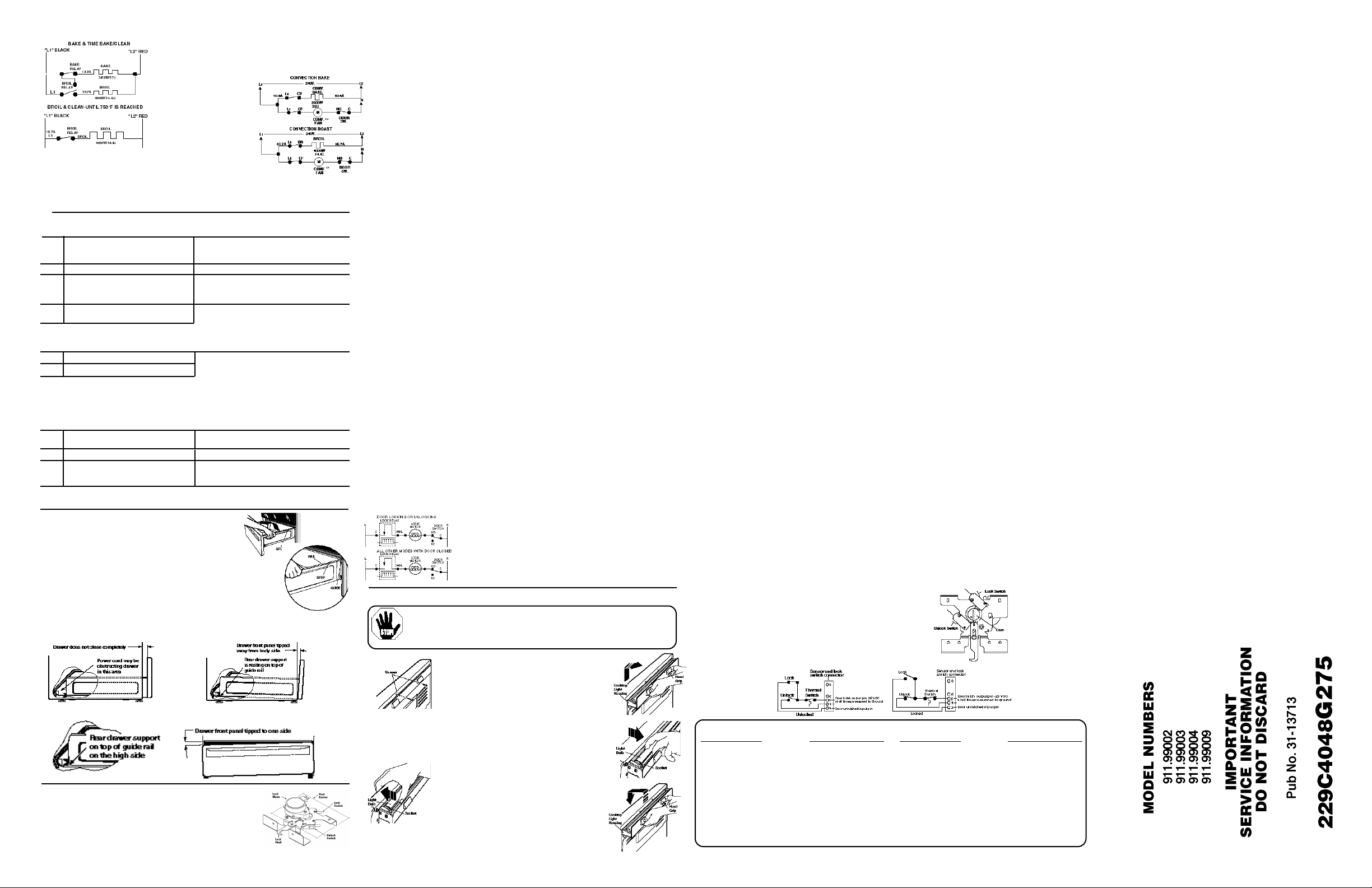
• BAKE/TIME BAKE — Bake and broil units cycle during
preheat and balance of operation, one unit is on at a time.
• CLEAN — Broil unit only on
during 1st 30 minutes or
until oven reaches 750°F.
During balance of clean
oven will cycle between
bake and broil units.
Convection fan running make the following checks:
• Check the voltage from terminal CF to N on control - should read
120V in convection bake or roast mode.
• If voltage is OK, check convection fan motor. It reads approximately 15-20Ω’s at room
temperature. Check to make sure fan shaft is not rubbing on oven liner.
ERC FAILURE CODES
CODE
• Look for high resistance in the sensor circuit due to high contact resistance (poor terminal crimp, deformed
• Electrical noise interference in the sensor circuit ( Ham radio, cordless phone, etc.)
• Measure each sensor lead from connector block to ground. If shorted, look for pinched or cut wire in sensor
• Check connector terminals- Look for deformed or corrosion on terminals. Repair or replace.
• Check connector at sensor (remove sensor and carefully pull leads with connector into oven).
• If all above is ok, replace control.
NOTE: Connections can be intermittent due to a corrosive buildup between the connection to the terminals, or
by being bent by the insertion of a probe, etc.
MEANING
Clear/Off pad is shorted or touch board fault
F0
(after approx. 100 secs).
Loss of element redundant driver protection.
F1
Any key (other than Start of Clear/OFF pad)
F7
shorted (after approx. 40 secs).
F6
F2
Over-temperature-915°F if lock circuit is
made, 615°F otherwise.
terminals, loose connection inside sensor tube) or intermittent solder joint.
Sensor circuits open (2900 Ohms or greater).
F3
Sensor circuits shorted (950 Ohms or less).
F4
to damage terminals in block)-Should read 1100Ω at room ambient (approx.72°F).
circuit.
Both lock and unlock circuits are activated at
F9
FC
the same time (after approx. 60 secs.)
Loss of door motor redundant driver protection.
FF
FA
Surface warmer on indicator light supervisor
error
FE
CORRECTION
If code cannot be cancelled, unplug keypad and
power up. If 0) ceases, replace keypad/ glass
asm., If 0) is still present, replace main control.
If code cannot be cancelled, replace control.
If code cannot be cancelled, unplug keypad and
power up. If code ceases, replace keypad/glass
asm. If code is still present, replace main control.
• Look for welded relay contacts. (Heating elements on
in off mode.)
• Disconnect power to range.
• Disconnect sensor connector at control. Measure
sensor resistance at control connector (take care not
Check wiring and test operation of switches.
Perform resistance check.
Replace control
Replace control
• T E C H N I C A L D A T A S H E E T •
STORAGE DRAWER REMOVAL
To Remove:
1. Pull the drawer out until it stops.
2. Lift the front of the drawer until the stops clear the guides.
3. Remove the drawer.
To Replace:
1. Place the drawer rail on the guides.
2. Push the drawer in until it stops.
3. Lift the front of the drawer and push in until the stops clear the guides.
4. Lower the front of the drawer and push in until it closes.
——— If Drawer Won’t Close ———
——— If Drawer is Crooked ———
MOTORIZED DOOR LOCK
The motorized door lock assembly is located above the oven. The
assembly consists of a lock motor cam and switch assembly, lock
hook, heat barrier, and mounting plate.
229C4059P244
Motorized Door Lock Operation:
The lock motor is energized when the control is set for Clean
and Clean Time selected. The K1 relay contact will close and
complete the circuit that supplies the voltage to the lock motor.
REPLACING THE COOKTOP LIGHT BULB
CAUTION: Disconnect electrical power to the range at the main circuit
breaker or fuse box before attempting to replace the cooktop light bulb. Do
not touch a hot light bulb with wet hands or a wet cloth. Wait until the bulb
has cooled and use a dry cloth.
To Remove Old Bulb:
1. Pull the range away from the wall.
2. Remove the two screws from the top on the
back of the range.
3. Pull up on the hand grips on the back of the range
until the tabs at the bottom of the cooktop light
housing separate from the back of the range.
4. Pull out the cooktop light housing as far as possible, about 2 inches.
5. Remove the light bulb by unplugging it from both sockets with one motion.
To Install New Bulb:
1. Install the new light bulb by plugging it into
both sockets with one motion.
2. Using the hand grips on the cooktop light
housing, lift up and push the housing back into
the rear wall of the range. Then lower the
housing until the bottom tabs are inserted back
into the range.
3. Reattach the screws along the top edge on the back of the range.
Then push the range back against the wall.
NOTE: Display of Control will flash “LOCK DOOR” if the door switch is in the “C” to “NC” position.
(Door open)
• The word “LOCKED DOOR” will flash on and off in the display while the
lock motor is in motion. When the door is locked the word “LOCKED
DOOR” remains illuminated in the display.
• CAM - The cam on the motor performs two functions:
1. Positions the lock hook in the door to prevent opening during clean
operation.
2. Operates the lock switches which tell the control if the door is unlocked or
locked and ready for clean operation.
NOTE: When door is either being locked or unlocked both lock switches will
be in the open position.
Kenmore ELITE Radiant Free-Standing
Part Description Repair Part Number
6" Haliant Element WB30K5033
Bridge Element WB30T10088
9"Haliant Element WB30T10035
6"Haliant Element (Warmer) WB30T10042
Infinite Switch (Warmer) WB24T10012
Infinite Switch (Dual) WB24T10015
Infinite Switch-2600W WB24T10032
Infinite Switch-1500W WB24T10028
Oven Control WB27T10137
Oven Control-Stainless WB27T10144
Sensor WB23T10002
Glass Panel Asm-Black WB27T10160
Part Description Repair Part Number
Glass Panel Asm-White WB27T10155
Glass Panel Asm-Bisque WB27T10159
Glass Panel Asm-GPH/ SS WB27T10157
Glass MT ASM-Black WB62T10040
Glass MT ASM-Bisque WB62T10039
Glass MT ASM-White WB62T10038
Glass MT ASM-GPH WB62T10037
Bake Element -Hidden WB44T10015
Convection Element WB44T10001
Broil Element WB44T10008
Halogen Lamp WB08T10007
30" RADIANT FREE-STANDING CONVECTION RANGE
IMPORTANT SAFETY NOTICE: This information is intended for use by individuals
possessing adequate backgrounds of electrical, electronic and mechanical experience.
Any attempt to repair a major appliance may result in personal injury and property
damage. The manufacturer or seller cannot be responsible for the interpretation of this
information, nor can it assume any liability in connection with its use.
DISCONNECT POWER BEFORE SERVICING
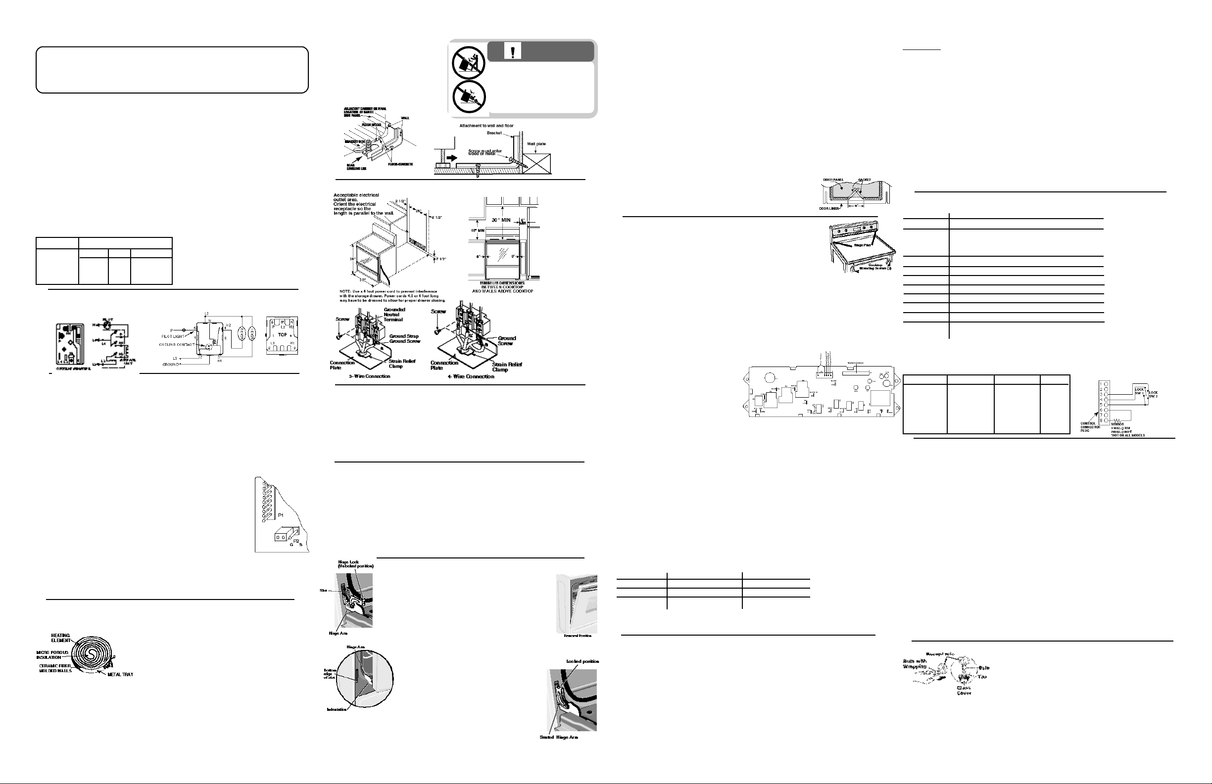
NOTE: Installation information for reference
only. See Installation Instructions shipped
with product for complete details and before
attempting to install.
Brackets should be attached to the floor or wall
to hold either right or left rear leg
leveler. Make sure leg leveler
reengages the bracket when range is moved
for any reason.
IMPORTANT: RECONNECT ALL GROUNDING DEVICES. All parts of this appliance capable
of conducting electrical current are grounded. If grounding wires, screws, straps, clips,
nuts, or washers used to complete a path to ground are removed for service, they must be
returned to their original position and properly fastened.
GROUNDING SPECIFICATIONS
Ground Path Resistance 0.10Ω Max.
Insulation Resistance 250KΩ Min.
INSTALLATION REQUIREMENTS
Power Supply: This appliance must be supplied with proper voltage and frequency, and
connected to an individual, properly grounded branch circuit, protected by a circuit
breaker or time delay fuse, as noted on rating plate. Wiring must conform to the National
Electrical Codes. The rating plate is located on the lower front frame behind the storage drawer.
Overcurrent Protection Ranges
NEC Rating Maximum Kilowatt Rating
35 Amp
40 Amp
50 Amp
208V
-
12.4
17.4
236V
12.4
15.4
21.4
240V
12.4
16.0
22.0
SURFACE UNIT SWITCHES
CURRENT SENSITIVE
CAUTION: This range connector block is
recognized for copper wire only, NOT
ALUMINUM WIRE. Refer to the installation
instructions for additional details.
SURFACE UNIT SWITCHES & CONTROLS
CONTROL TYPES:
Aluminum Wire
VOLTAGE SENSITIVE
GLASS CONTROL PANEL ASSEMBLY
The glass crystal assembly should only be removed when it needs to be replaced. All other
components, except infinite switches, are accessed from the back of the control panel assembly. The
infinite switches can be unscrewed from the front without removing the glass crystal assembly and
then removed from the back of the control panel assembly.
Replacing Infinite Switches
1. Turn the power off to the unit.
The Temperature Limit/Hot Light Switch performs two functions:
1. Keeps the Hot Light on until the glass surface above the heating unit has cooled below
2. Detects when glass temperature above a unit has exceeded its limit of approximately 1031°F
2. Remove knobs.
3. Unscrew 4 crystal retainer nuts. These must be hand tightened only.
4. Remove the two screws holding the infinite switch.
5. Remove control panel per instructions. ( ref. Section on Control Panel
Removal).
6. From the rear of the control panel assembly, unplug wires and remove
infinite switch.
7. Repeat steps in reverse order to reassemble the unit.
Removing Glass Crystal Assmbly
1. Turn the power off to the unit.
2. Remove all knobs.
3. Unscrew all crystal retainers while holding the glass crystal against the
control trim. The retainers must only be hand tightened.
Verify proper
location of jumper
P2 (on G)
The temperature limit/hot light switch cannot be calibrated.
The left front and right front element have two cooking zones:
• To use the large 9" cooking area or bridge, push to turn the control knob clockwise to desired
• To use the small 6" cooking area, push to turn the control knob counter clockwise to desired
When a cooking zone is activated, coils beneath the zone radiate heat through the glass cooktop
to the utensil. The red glow of the coils will be visible through the glass. It will take the cooking
zone on the glass surface a few moments to heat up. The coil cycles on and off to maintain your
selected control setting.
4. Move the glass crystal about 3 inches away from the control panel and unplug the harness
from the panel.
5. Repeat steps in reverse order to reassemble the unit.
NOTE: When the glass crystal assembly is removed for any reason, the crystal gaskets must be
replaced with new ones.
RADIANT HEATING ELEMENT SYSTEMS
Heating Elements: The radiant heating element consists of a spiral wound resistance wire attached
to micro porous insulation with molded ceramic fiber walls in a corrosion protected metal tray.
The Heating Elements come in 4 sizes:
• 6" - 240 Volt 1500 Watts
• 6"- 120 Volt 120 Watts (Note: The warmer will not glow
red like the cooking elements.)
• 9" - 240 Volt 2500 Watts (Dual Unit 6" & 9")
• Bridge - 240 Volt 2600 Watts
TEMPERATURE LIMIT/HOT LIGHT SWITCH
150°F. (After the heating element has been turned off.)
and disconnects power to that unit. When glass temperature cools below 1031°F, the unit will
turn back on.
setting.
setting.
To Remove:
1. Fully open the door.
2. Push the hinge locks down toward the door frame, to the
unlocked position. This may require a flat blade screwdriver.
3. Firmly grasp both sides of the door at the top.
4. Close door to the door removal position.
5. Lift door up until the hinge arm is clear of the slot.
HOT SURFACE INDICATOR LIGHT
The hot surface indicators are on turned by contacts within the heating element temperature
limiters. When glass temperature over a cooking element reaches 150°F, its hot surface indicator
light is activated to alert consumers that glass surface is too hot to touch. When the warmer element
is turned on, the hot surface indicator display is activated to alert consumers that the glass surface
may be hot. The surface indicators will remain activated until the glass surface temperature has
cooled below 150°F.
2. Fully open the door.
3. Push the hinge locks up against the front frame of the oven cavity, to
the locked position.
4. Close the oven door.
229C4059P244
• T E C H N I C A L D A T A S H E E T •
WARNING
• All ranges can tip
• Injury to persons could result
• Install anti-tip
device packed with range
• See Installation Instructions
MINIMUM CLEARANCES
*
*
NOTE: Effective
January 1, 1996, the
National Electrical
Code requires that new
or rewired
construction utilize a
4-conductor
connection to an
electric range.
DUAL CIRCUIT CONTROL
REMOVABLE OVEN DOOR
To Replace:
1. Firmly grasp both sides of the door at
the top, with the door at the same angle
as the removal position, seat the
indentation of the hinge arm into the
bottom edge of the hinge slot.
* RECOMMENDED
SPACING TO HEAT
SENSITIVE
SURFACES.
Cooling Air Flow Air enters the door assembly through large slots in the bottom and
flows upward between the inner and outer assemblies, exhausting through slots in the
top of the door. DO NOT INSULATE THIS AIR CHANNEL.
To Service Full Glass Door
1. Complete door assembly:
• Remove three screws from the bottom
door frame.
• Remove two screws at the top of the
door on the liner.
• The liner assembly and outer glass
panel assembly can now be separated.
2. Outer glass panel assembly:
• Remove four screws from the side posts at the bottom.
• Remove four screws from the side posts at the top
near the door vent trim.
• Slide the bottom trim and top vent trim out to free the
outer door glass. Note: On some doors the bottom
trim is sealed to the outer door glass and cannot be
separated.
3. Liner assembly:
• Remove three screws on each side of the door liner to remove the door hinge assembly.
• Remove four screws from the insulation retainer.
• Remove insulation retainer and then the insulation.
• The window pack and window gasket are now accessible, on units with a window door.
Door Gasket
The door gasket is clipped into the liner of the door panel.
To Service Gasket A 6" gap must be left in the gasket at bottom of door.
The gap is required to provide air flow in the oven for proper baking results.
COOKTOP REMOVAL
The cooktop is fastened to the front frame by two (2) screws. Remove the
2 screws and lift the back edge of cooktop upward (no more than 1 to 2
inches) to unhook the cooktop hinge from the backguard pins. Pull
forward. Unplug harness and unscrew ground wire located at rear of
cooktop. Lift cooktop off. NOTE: Raising cooktop too high can break the
glass.
Ceramic Glass Cooktop-
The ceramic glass is sealed into the COOKTOP and will
be supplied as a complete assembly.
CONTROL PANEL REMOVAL
The control panel contains the ERC, infinite heat switches and key pad/ glass assembly.
To Service:
1. Remove 2 screws (from bottom) securing control panel to the backguard.
2. Loosen 2 outside screws at the top, in the back of the range.
3. Pull bottom of panel out while lifting panel up.
4. Lay panel on cooking surface.
CAUTION: Place protective covering (such
as towel) between control panel and cooking
surface to avoid damage to control panel.
ERC
To Remove:
1. Turn the power off to the unit.
2. Slide the unit out so that the left side of the unit can be accessed freely.(When facing the range).
3. Remove cooktop per instructions in Cooktop Removal Section.
4. Remove three screws from the radiant brace.
5. Remove three screws from the back of the unit that attaches the side panel.
6. Remove one screw from the front of the unit that attaches the side panel.(Remove drawer to access.)
7. Lift the panel up and then out to remove.
8. Unplug the bake element.
9. Note the screw with the ground wire. Remove four screws attaching the side insulation retainer. Lift
the oven insulation up and push it under the radiant brace to hold out of the
10. Remove two screws and side to the element heater box.
11. Slide the hidden bake assembly out from the side.
To Replace:
1. Make sure you plug the wires back into the element and leads are placed back into the
tab in the retainer.
2.Reverse steps 1 through 11 above.
CONTROL VOLTAGE
Terminals
L1-N
L1A-BAKE
L1A-BROIL
L1A-CONV
L1-L2 *
L1A-N
IN-WM-N
COM-MDL
N- LIGHT
L1-OUT WM
L1 SURFACE
** L1-CF
OVEN SENSOR AND DOOR SWITCH OHMMETER TEST
Remove power from oven. Make resistance measurement from side of sensor & lock
switch connector with exposed terminals, disconnected from control.
CIRCUIT CONDITION TERMINALS OHMS
Oven Sensor Room Temp 6 to 8 1100Ω
Clean Temp 6 to 8 2650Ω
Unlatch Unlatched 3 to 5 0Ω
The Electronic Range Control system
consists of the control assembly, keypad/
Latch Latched 3 to 5 Open
glass assembly, oven sensor, door latch/ switch assembly.
Key Panel
The key panel is an electronic ( field disturbance) method using no moving parts. The circuit
board is conformally coated. It receives DC power from the ERC main control. It cannot be tested
separately from the control.
Voltage checks at the connector:
12 VDC from J1 pins 1 to 4.
12 VDC from J1 pins 1 to pins 16, 17, 18 when no keys are touched.
Key Panel Test
The keypad must have the designed minimum air clearance behind it to operate properly. A warped or
bent steel control panel could prevent some keys from operating. Depress each pad. The following
should occur:
• Bake, Broil, Convection Roast, Convection Bake, Clean, Kitchen Timer, Clock, Delay Start , Favorite
Recipe and Cook Time - Audible beep and display shows response corresponding to the key.
• Multi Stage- Press Bake, Cook Time, Up Min, Multi Stage. Display shows MULTI word.
• Warmer On/Off: Audible beep and display shows response.
• Warmer Power Level: Must press Warmer On/Off first. Select levels 1-3 as shown in display.
Power Level
1
2
3
•
Control Lockout- Audible beep. Hold 2 keys 5 seconds to activate. Hold 2 keys 5 seconds to deactivate.
Element off-time
4.6 sec
10.6 sec
7.2 sec
Element on-time
19 sec
13 sec
16.4 sec
• Clear/Off - Audible beep, display clears to time of day except for Kitchen Timer and Warming Zone.
The control has a section that can be entered to change how the control will work. To enter this
section: Press and hold BAKE and BROIL pads for 3 seconds and “SF” appears in display.
Select the area to change. When the change has been made, press START to return to Time of
Day.
• End of Cycle Tone - Press TIMER pad. *Display shows Con Beep when control is set for
Continuous End of Cycle Tone or Beep when set for Non-Continuous.
• °F or °C - Press Broil pad. *Display will show either F° or C°. Press Broil pad again to change.
• 12 hour, 24 hour, or blank out Time of Day Clock - Press Clock pad. *Display will show 12 hr,
24 hr, OFF for blank clock. Press again to change.
• Cook & Hold - used only with Time Bake or Delay Bake functions - Press Cooking Time pad.
*Display will show either HLd ON or HLd OFF. Press again to change.
• Child Lockout - Press CLEAN. *Display will show LOC ON (when any heating functions are
tried display will show OFF), press CLEAN again for LOC OFF, control unlocked.
• 12 hour shutdown comes set to shut down after 12 hours of continuous operations; this can be
eliminated - Press Delay Start pad. *Display will show no shdn. To turn back on, press Delay
Start pad again and display will show 12 shdn.
• Sales Mode, special feature added for sales floor demonstration - Press Clock & Timer pads at
the same time. *Display will start to cycle through the different modes of operation.
• Slew Rate- Press up or down to change slew.
• Use Temperature Offset- Press Bake Pad to change temperature offset.
• Surface warmer Shut Down Override- Press the Surface Warmer ON/OFF. Display shows No or
3:00 for three hour shut down.
BACKGUARD COMPONENT ACCESS
To access backguard component remove backguard assembly
1. Remove 2 screws (from bottom) securing control panel to the backguard.
2. Remove 2 screws at the top, in the back of the range.
3. Pull bottom of panel out while lifting panel up.
4. Lay panel on cooking surface.
CAUTION: Place protective covering (such as towel) between control panel and
cooking surface to avoid damage to control panel.
To replace Backguard assembly
1.Make sure 2 green ground leads are connecting outer infinite switches to mainback.
2. Reverse step 1 through 4 above.
To Replace
1. Wrap the bulb first. Push straight in, all the way. (Do not touch the bulb with fingers.)
2. Reverse steps 1 through 2 above.
3. Use only 120 volt and 35 watt Halogen Bulb.
HIDDEN BAKE HEATER ELEMENT
way.
VOLTAGE
120 VAC ALL THE TIME
240 VAC when oven is not calling for heat
(BAKE, CONV. & BROIL relay contacts open)
240 VAC all the time
120 VAC all the time
120 VAC when warmer is greater than 150°F
120 VAC when door is locking
120 VAC when oven light is not on
120 VAC when warmer is off
120 VAC when top light is off
120 VAC when oven door is closed and convection mode is
not operating
Oven Sensor/Lock Sw. Connector
4 to 5 Open
4 to 5 0Ω
NOTE: Temperature/
Mode Selection
Necessary for
operation of relay
contacts.
NOTE: Voltage must
be present across
terminals L1 to N for
control to operate.
* Voltage must be
present across
L1-L2 terminals
for warming zone
to operate.
SPECIAL FUNCTIONS
OVEN LIGHT REMOVAL
To Remove
1. Disconnect electrical power to the oven at the main circuit
breaker or fuse box.
2. Turn the glass cover counterclockwise 1/4 turn until the tabs
of the glass cover clear the grooves of the socket.
3. Pull straight out to remove the bulb.
 Loading...