

Kenmore 795.78773.801, 795.78789.801, 795.78779.801, 795.78783.801 Service Manual
CAUTION
BEFORE SERVICING THE UNIT,
READ THE SAFETY PRECAUTIONS IN THIS MANUAL.
REFRIGERATOR
SERVICE MANUAL
R
795.78773.801
795.78779.801
795.78783.801
795.78789.801
P/No. MFL57156802
Model #s:

SAFETY PRECAUTIONS....................................................................................................................................................... 2
1. SPECIFICATIONS............................................................................................................................................................... 3
2. PARTS IDENTIFICATION................................................................................................................................................... 4
3. DISASSEMBLY.............................................................................................................................................................. 5-14
REMOVING AND REPLACING REFRIGERATOR DOORS ...............................................................................................5
DOOR INSTALLATION....................................................................................................................................................... 6
DOOR.............................................................................................................................................................................. 7-8
TO REMOVE THE DISPENSER .........................................................................................................................................8
DOOR ALIGNMENT............................................................................................................................................................8
FAN AND FAN MOTOR(Evaporator).................................................................................................................................. 8
ICE FAN SCROLL ASSEMBLY REPLACEMENT ..............................................................................................................9
DEFROST CONTROL ASSEMBLY.................................................................................................................................... 9
LAMP.................................................................................................................................................................................. 9
CONTROL BOX-REFRIGERATOR.................................................................................................................................... 9
MULTI DUCT.................................................................................................................................................................... 10
MAIN PWB, DISPLAY PWB REPLACEMENT, FUNNEL REPLACEMENT......................................................................10
SUB PWB FOR DISPENSER, DUCT DOOR REPLACEMENT, ICE CORNER DOOR
REPLACEMENT, ICE MAKER ASSEMBLY.......................................................................................................................11
AUGER MOTOR COVER, AUGER MOTOR REPLACEMENT.........................................................................................12
DOOR ICE BIN..................................................................................................................................................................13
HOW TO REMOVE AND REINSTALL THE PULLOUT DRAWER...............................................................................14-17
4. ADJUSTMENT............................................................................................................................................................. 18-19
COMPRESSOR................................................................................................................................................................ 18
PTC-STARTER................................................................................................................................................................. 18
OLP(OVERLOAD PROTECTOR)......................................................................................................................................19
TO REMOVE THE COVER PTC.......................................................................................................................................19
5. CIRCUIT DIAGRAM.......................................................................................................................................................... 20
6. TROUBLESHOOTING................................................................................................................................................. 21-25
COMPRESSOR AND ELECTRIC COMPONENTS.......................................................................................................... 21
OTHER ELECTRICAL COMPONENTS ........................................................................................................................... 22
SERVICE DIAGNOSIS CHART........................................................................................................................................ 23
REFRIGERATION CYCLE.......................................................................................................................................... 24-25
7. OPERATION PRINCIPLE & REPAIR METHOD OF ICEMAKER .............................................................................. 26-28
8. DESCRIPTION OF FUNCTION, CIRCUITS & ERROR CODES..................................................................................29-45
9. EXPLODED VIEW & REPLACEMENT PARTS LIST ..................................................................................................... 46-
CONTENTS
- 2 -
Please read the following instructions before servicing your
refrigerator.
1. Unplug the power before handling any elctrical
componets.
2. Check the rated current, voltage, and capacity.
3. Take caution not to get water near any electrical
components.
4. Use exact replacement parts.
5. Remove any objects from the top prior to tilting the
product.
SAFETY PRECAUTIONS

- 3 -
1-1 DISCONNECT POWER CORD BEFORE
SERVICING
IMPORTANT – RECONNECT ALL
GROUNDING DEVICES
All parts of this appliance capable of conducting electrical
current are grounded. If grounding wires, screws, straps,
clips, nuts or washers used to complete a path to ground
are removed for service, they must be returned to their
original position and properly fastened.
1-2 IMPORTANT NOTICE
This information is intended for use by individuals
possessing adequate backgrounds of electrical, electronic
and mechanical experience. Any attempt to repair a major
appliance may result in personal injury and property
damage. The manufacturer or seller cannot be responsible
for the interpretation of this information, nor can it assume
any liability in connection with its use.
1-3 ELECTRICAL SPECIFICATIONS
Temperature Control (F )...-6°F to +8°F
Defrost Control......Total Comp Running Time: 7 hrs~50 hrs
Defrost Thermostat.......................................................46°F
Electrical Rating : 115VAC, 60Hz.................................6.1 A
Maximum Current Leakage.......................................0.5 mA
Maximum Ground Path Resistance....................0.14 Ohms
Energy Consumption .....25 cu.ft. 547 kWh/yr (Energy Star)
1-4 NO LOAD PERFORMANCE
CONTROL POSITION: MID/MID
And Ambient of: ..................70°F..................................90°F
Fresh Food, °F....................33°F to 41°F.........33°F to 41°F
Frozen Food, °F..................-4°F to +4°F..........-4°F to +4°F
Percent Running Time........35%-45%.................50°F-70°F
1-5 REFRIGERA TION SYSTEM
Minimum Compressor Capacity Vacuum ............... 21 MIN.
Minimum Equalized Pressure
@ 70°F ....................................................... 49 PSIG
@ 90°F ....................................................... 56 PSIG
Refrigerant R134a ................................................. 4.76 oz.
Compressor ..................................................... 950 BTU/hr
1-6 INSTALLATION
Clearance must be provided at top, sides and rear of the
refrigerator for air circulation.
AT TOP ......................................................................... 2 in
AT SIDES ...................................................................... 1 in
AT REAR ...................................................................... 1 in
1-7 REPLACEMENT PARTS
25 cuft
795.78773.801 795.78783.801
795.78779.801 795.78789.801
Relay ............................................................
Defrost Thermostat........................................6615JB2005H
Defrost Heater...............................................5300JK1005D
Evaporator Fan Motor....................................4681JK1004E
Capacitor (Running)...................................0CKZZJB2012K
(0CKZZJB2014B)
(0CKZZJB2012H)
Compressor (Hi-Side) 252JA1006N
Evaporator (Lo-Side)......................................5421JJ1007A
Condenser....................................................ACG36653801
Dryer..............................................................5851JA2002P
Condenser Fan Motor ...................................4681JB1029D
Temperature Control ............................ACQ36820503(WB)
ACQ36820505(STS)
Main Control .................................................EBR41956408
Ice Fan Motor................................................EAU36179303
1-8 AIR FLOW / CIRCULATION D’AIR
1. SPECIFICATIONS
EVAPORTOR FAN MOTOR
CONDENSER FAN MOTOR
Glide'N'Serve
- 4 -
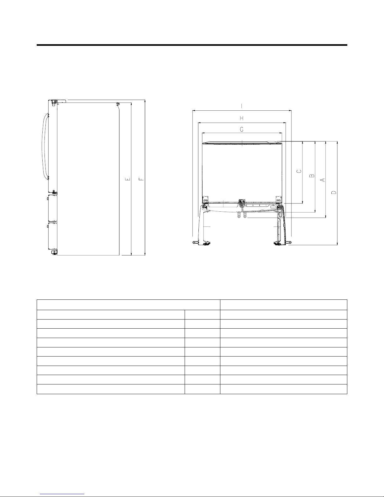
1-9 DIMENSIONS
Description 795.787**, 795.785**
Depth w/ Handles A 34 1/4 in.
Depth w/o Handles B 31 3/4 in.
Depth w/o Door C 27 7/8 in.
Depth (Total with Door Open) D 46 1/2 in.
Height to Top of Case E 68 3/8 in.
Height to Top of Door Hinge F 69 3/4 in.
Width G 35 3/4 in.
Width (door open 90 deg. w/o handle) H 39/1/4 in.
Width (door open 90 deg. w/ handle) I 44 1/4 in.
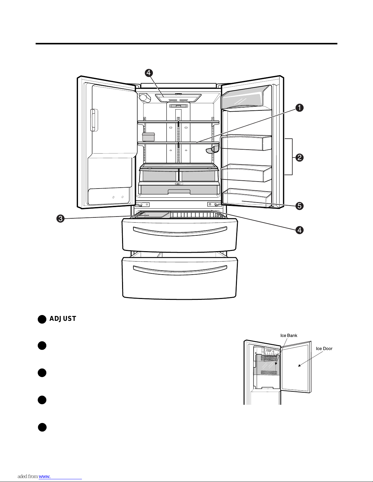
2. PARTS IDENTIFICATION
- 5 -
3
4
5
1
2
4
ADJUSTABLE REFRIGERATOR SHELVING
The refrigerator compartment shelves are adjustable to
allow flexibility for storage needs.
MODULAR DOOR BINS
Three interchangeable bins can be arranged to suit your
storage needs.
REMOVABLE ICE STORAGE BIN
The ice storage bin can be removed to fill ice
buckets,coolers,or pitchers.
INTERIOR LAMPS
Two separate LED arrays light the freezer and refrigerator
interiors.
FIXED DOOR BIN
1
2
3
4
5
Ice Bank
Ice Door

- 6 -
3. DISASSEMBLY
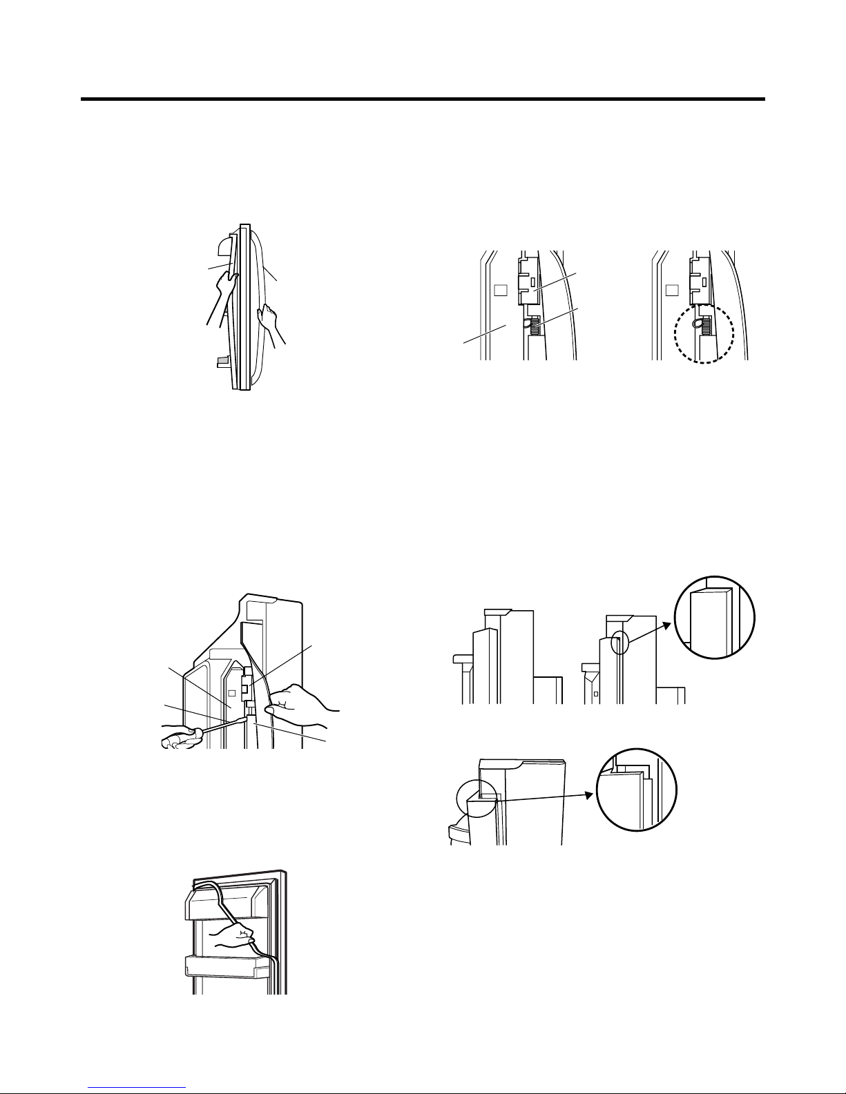
3-1 REMOVING AND REPLACING REFRIGERATOR DOORS
● Removing Refrigerator Door
ww
CAUTION: Before you begin, unplug the refrigerator. Remove food and bins from doors.
uu
Left Door -FIG. 2
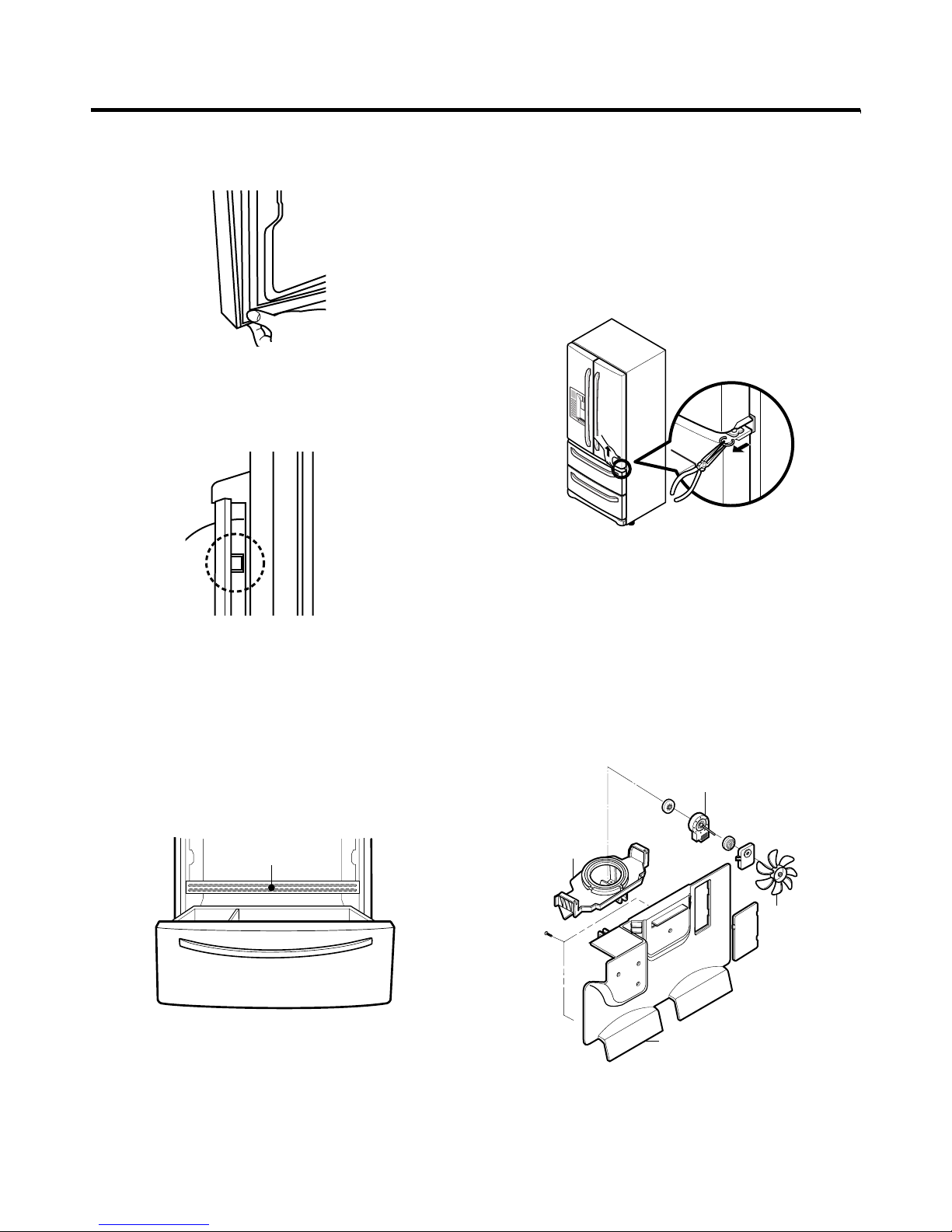
1. Disconnect water supply tube by pushing back on the disconnect ring (4).-FIG. 1
2. Open door. Loosen top hinge cover screw (1).
Use flat tip screwdriver to pry back hooks on front underside of cover (3). Lift up cover.
3. Disconnect door switch wire harness (2). Remove cover.
4. Pull out the tube.
5. Disconnect the three wire harnesses (5). Remove the grounding screw (6).
6. Rotate hinge lever (7) counterclockwise. Lift top hinge (8) free of hinge lever latch (9).
ww
CAUTION: When lifting hinge free of latch, be careful that door does not fall forward.
7. Place door, inside facing up, down onto a non-scratching surface.
uu
Right Door -FIG. 3
1. Open door. Loosen top hinge cover screw (1). Lift up cover (3).
2. Disconnect door switch wire harness (2). Remove cover.
3. Disconnect wire harness (5).
4. Rotate hinge lever (6) clockwise. Lift top hinge (7) free of hinge lever latch (8).
ww
CAUTION: When lifting hinge free of latch, be careful that door does not fall forward.
5. Lift door up from middle hinge pin (9).
6. Place door, inside facing up, down onto a non-scratching surface.
4
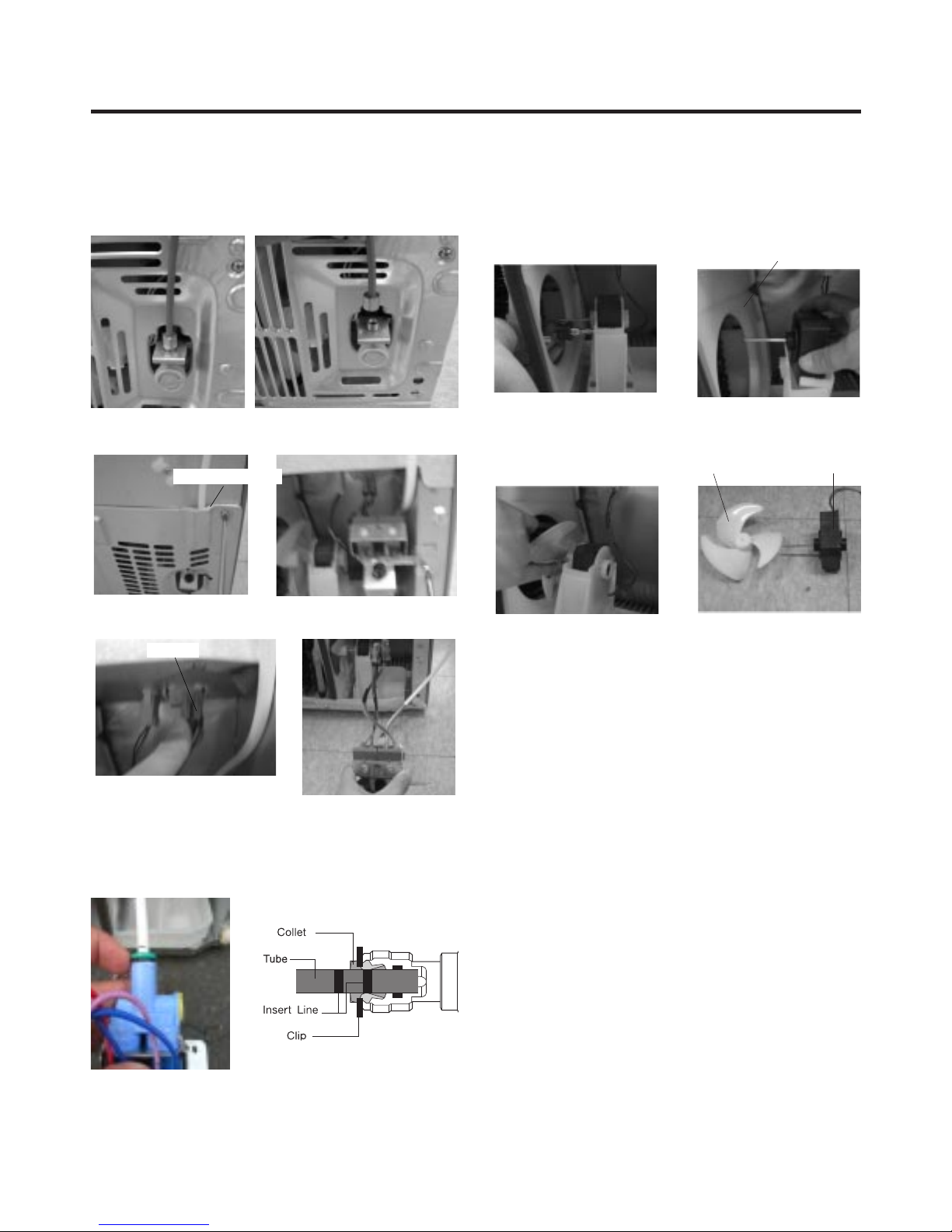
1) Insert the tube until you can see only one of the lines
printed on the tube.
2) After inserting, pull the tube to ascertain that it is secure.
3) Assemble clip.
Correct
Incorrect
(1)
(2)
(4)
(3)
(6)
(7)
(8)
(5)
(1)
(2)
(3)
(4)
(5)
(6)
Figure 2
Figure 3
Figure 1
- 7 -
3-2 DOOR
● Door Gasket Removal
1. Remove door frame cover
Starting at top of cover and working down, snap cover
out and away from door.
2. Remove gasket bracket clips
There are two clips on each door. Start bracket removal
near one of the middle clips.
1) Pull gasket back to expose gasket bracket clip and
door frame.
2) Insert a flat tip screwdriver into seam between gasket
bracket and door frame and pry back until clips snap
out.
3) Continue prying back along seam until all clips snap
out.
3. Remove gasket
Pull gasket free from gasket channel on the three
remaining sides of door.
● Door Gasket Replacement
1. Insert gasket bracket clips
1) Insert gasket bracket edge beneath door frame edge.
2) Turn upper gasket bracket spring so that the spring
ends are in the door channel.
3) Push in clip until you hear it snap securely into place.
4) Push in remaining clip until you hear it snap securely
into place.
Note: Make sure that no part of gasket bracket edge
protrudes from beneath door frame edge.
2. Insert gasket into channel
1) Snap gasket assembly into the door bracket.
<Inserting the Gasket Assembly into the Bracket Door>
Frame Cover
Handle
Door
Frame
Gasket
Bracket Clip
Flat Tip
Screwdriver
Gasket
Bracket
Figure 1
Figure 2
Figure 3
Door
Frame
Gasket
Bracket Clip
Spring
IncorrectCorrect
Incorrect
Correct
Figure 4
Figure 5
- 8 -
2) Press gasket into channels on the three remaining
sides of door.
3. Replace door frame cover
Starting at top of cover and working down, snap cover
back into door.
ww
CAUTION
• DO NOT ATTEMPT TO REMOVE THE MULLION
BETWEEN THE TWO DRAWERS. THERE IS A HOT
GAS HEAT LOOP (REFRIGERANT LINES) THAT
RUNS THROUGH THE MULLION.
• The rear panel can be easily removed after removing the
left and right upper door supports.
The panel can then be slid through the upper door
opening above the mullion!
.
3-3 DOOR ALIGNMENT
If the space between your doors is uneven, follow the
instructions below to align the doors:
1. With one hand, lift up the door you want to raise at
middle hinge.
2. With other hand, use pliers to insert snap ring as shown.
3. Insert additional snap rings until the doors are aligned.
(Three snap rings are provided with unit.)
3-4 FAN AND FAN MOTOR(EVAPORATOR)
1. Remove the freezer shelf. (If your refrigerator has an
icemaker, remove the icemaker first)
2. Remove the plastic guide for slides on left side by
unscrewing phillips head screws.
3. Remove the grille by removing one screw and pulling the
grille forward.
4. Remove the Fan Motor assembly by loosening 2 screws
and disassembling the shroud.
5. Pull out the fan and separate the Fan Motor and Bracket.
REFRIGERANT
LINES
Figure 6
Figure 8
Figure 7
GRILLE
FAN MOTOR
FAN
BRACKET
MOTOR
Figure 9
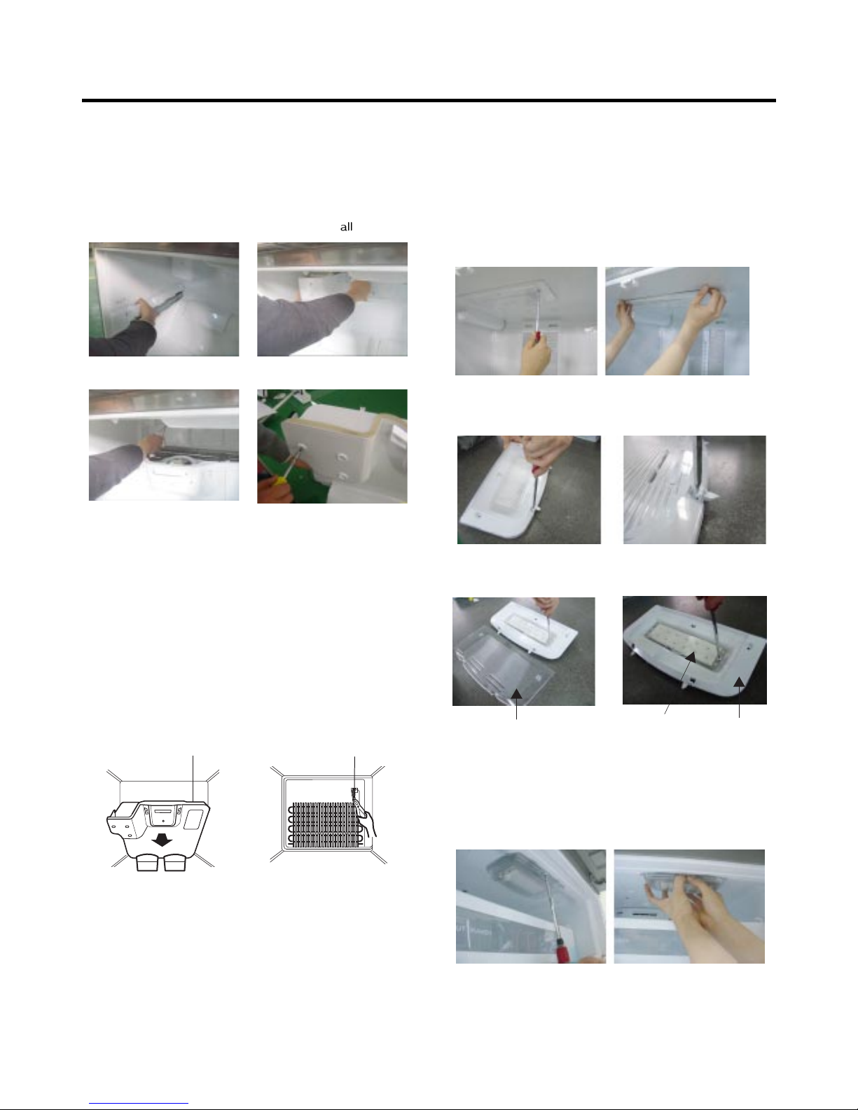
* Ice Fan Scroll Assembly Replacement
1) Remove the plastic guide for slides on left side by
unscrewing phillips head screws.
2) Pull the grille forward as shown in the second picture.
3) Disconnect wire harness of the grille
4) Remove the scroll assembly by loosening
screws
3-5 DEFROST CONTROL ASSEMBLY
Defrost Control assembly consists of Defrost Sensor and
FUSE–M.
The Defrost Sensor works to defrost automatically. It is
attached to the metal side of the Evaporator and senses its
temperature. At 72°C, it turns the Defrost Heater off.
Fuse-M is a safety device for preventing over-heating of
the Heater when defrosting.
1. Pull out the grille assembly. (Figure 10)
2. Separate the connector with the Defrost Control
assembly and replace the Defrost Control assembly
after cutting the Tie Wrap. (Figure 11)
3-6 LAMP
Unplug Refrigerator, or disconnect power at the circuit
breaker.
If necessary, remove top shelf or shelves.
3-6-1 Refrigerator Compartment Lamp
1) Release 2 screws.
2) Hold both ends with your both hands and pull it
downward to remove it.
3) Use a flat tool as shown below to remove
the cover lamp.
4) As shown below, use a flat tool to remove
the cover lamp.
3-6-2 Freezer Compartment Lamp
1. Unplug refrigerator power cord form outlet.
2. Remove screw with driver.
3. Grasp the cover Lamp,pull the cover downward.
- 9 -
GRILLE ASSEMBLY
Figure 10
DEFROST-CONTROL
ASSEMBLY
Figure 11
Figure 12
Figure 13
Cover, Lamp
Case Lamp
LED, Assembly
Figure 14
Figure 15
(1) (2)
(3) (4)
- 10 -
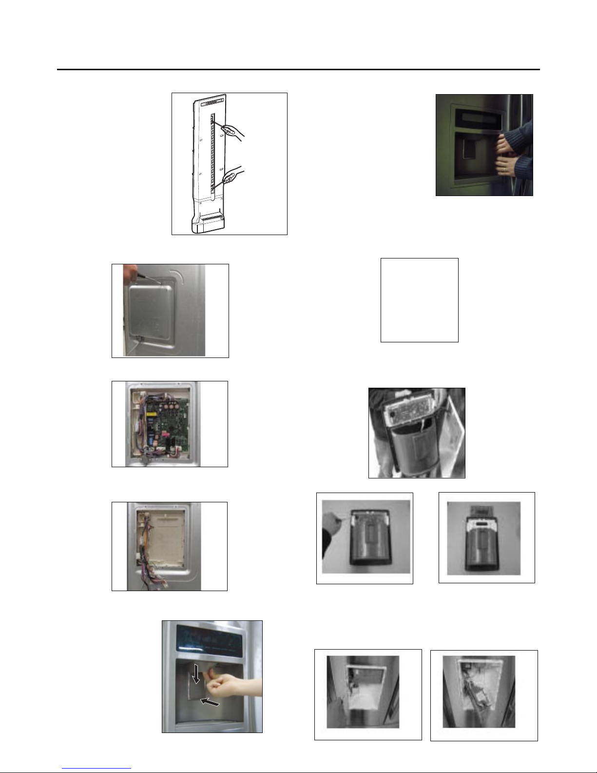
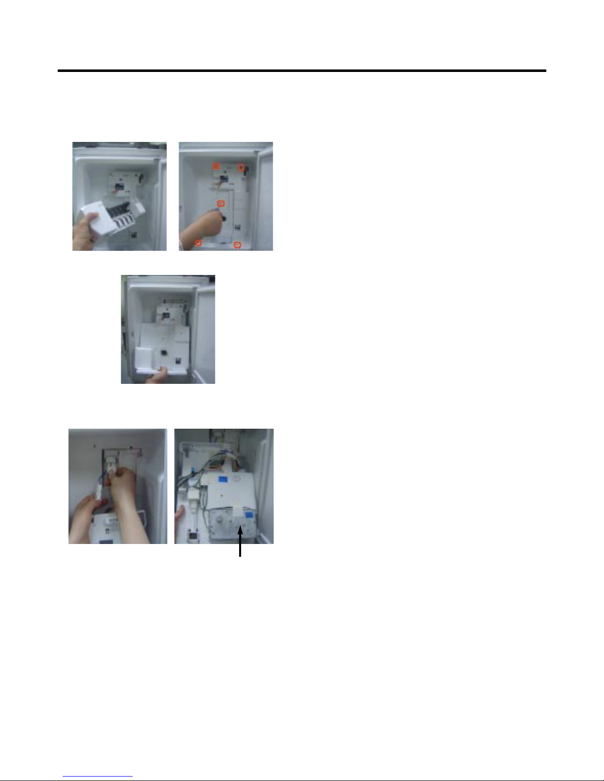
3-7 MULTI DUCT
1. Remove the upper and
lower Caps by using a flat
screwdriver, and remove
2 screws. (Figure 17)
2. Disconnect the lead wire
on the bottom position.
3-8 MAIN PWB
1) Loosen the 4 screws on the PWB cover.
2) Remove the PWB cover
3) Disconnect wire harness and replace the main PWB in
the reverse order of removal.
3-9 DISPENSER
1) Disconnect funnel and
button assembly by
pulling down and
forward.
2) Hold the left and right side of
the “Cover Assembly,
dispenser” as shown in the
picture, and pull and remove
it. The cover dispenser is
attached with a hook.
ww
CAUTION: When replacing the dispenser cover in the
reverse order of removal, be careful that the lead wire
does not come out and the water tube is not pinched by
the dispenser cover, as shown in the picture below.
3-10 DISPLAY PWB REPLACEMENT
1) Pull up and out on the dispenser cover to remove.
2) Follow the
steps in the pictures
3-11 FUNNEL REPLACEMENT
1) Pull up and out on the dispenser cover to remove.
2) Disconnect the wire harness.
3) Replace in reverse order.
Figure 17
- 11 -
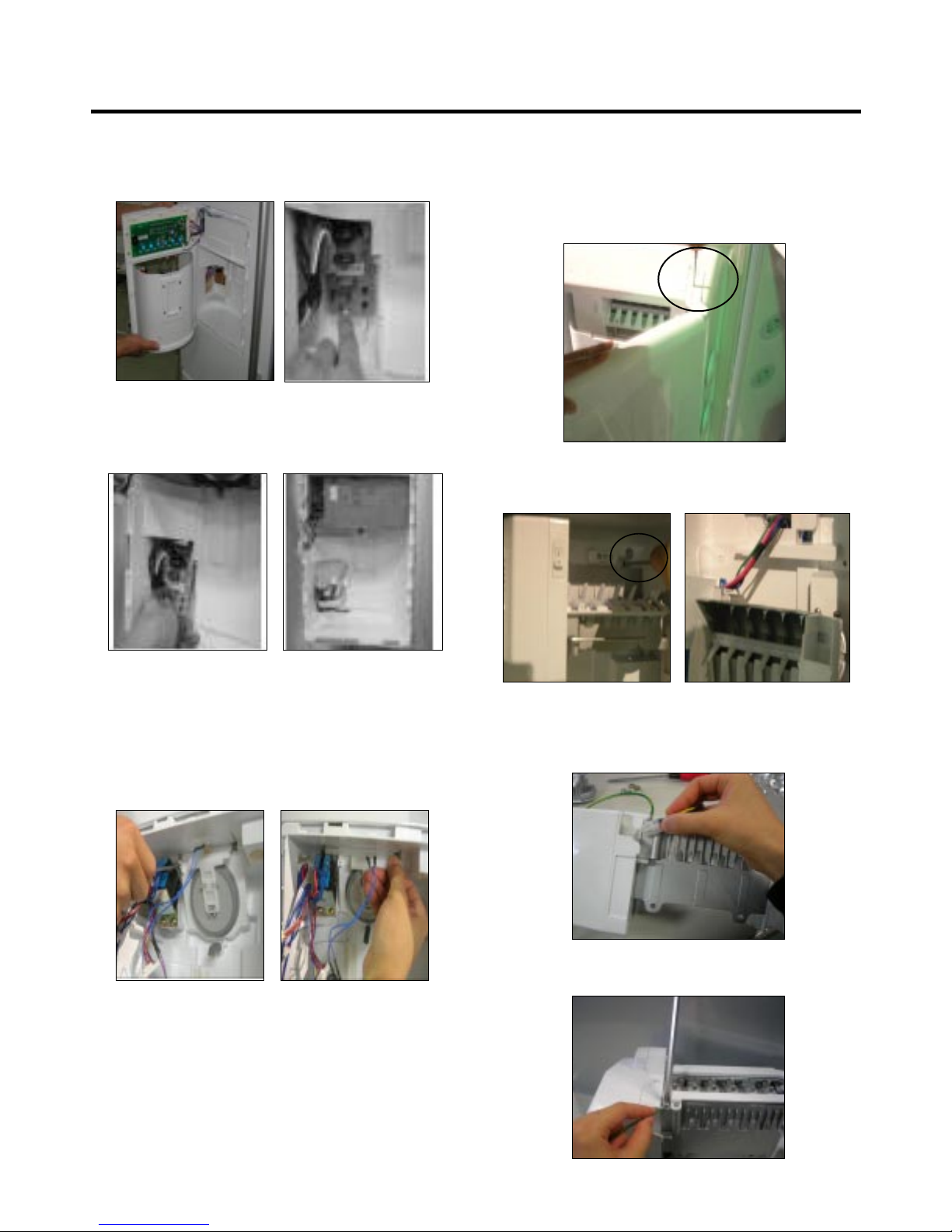
3-12 SUB PWB FOR WORKING DISPENSER
1) Loosen the screw on the sub PWB.
2) Pull the sub PWB down.
3) Disconnect the wire harness and replace the sub PWB
in the reverse order of removal.
3-13 DUCT DOOR REPLACEMENT
1) Pull up and out on the dispenser cover to remove.
2) Disconnect the wire harness.
3) Remove the funnel
4) Replace in reverse order.
3-14 ICE CORNER DOOR REPLACEMENT
1) Loosen the front screw as shown in the picture.
2) Lift up the hinge with one hand.
3) Pull out the Ice Corner Door with the other hand.
3-15 ICEMAKER ASSEMBLY
1) Loosen two screws as shown in the first picture.
2) Disconnect the wire harness & ground screw replace
theIcemaker assembly in the reverse order of removal.
3) It separates a ground connection screw.
hinge
3-17 AUGER MOTOR COVER
1) After removing the icemaker remove the (5) stainless
screws holding the auger motor cover, shown in the
picutres below.
2) Grip the bottom of motor cover assembly and pull out it.
3) Disconnect wire harness of motor cover assembly.
There is a auger motor on the back, as shown in the
picture.
Auger Motor
- 12 -
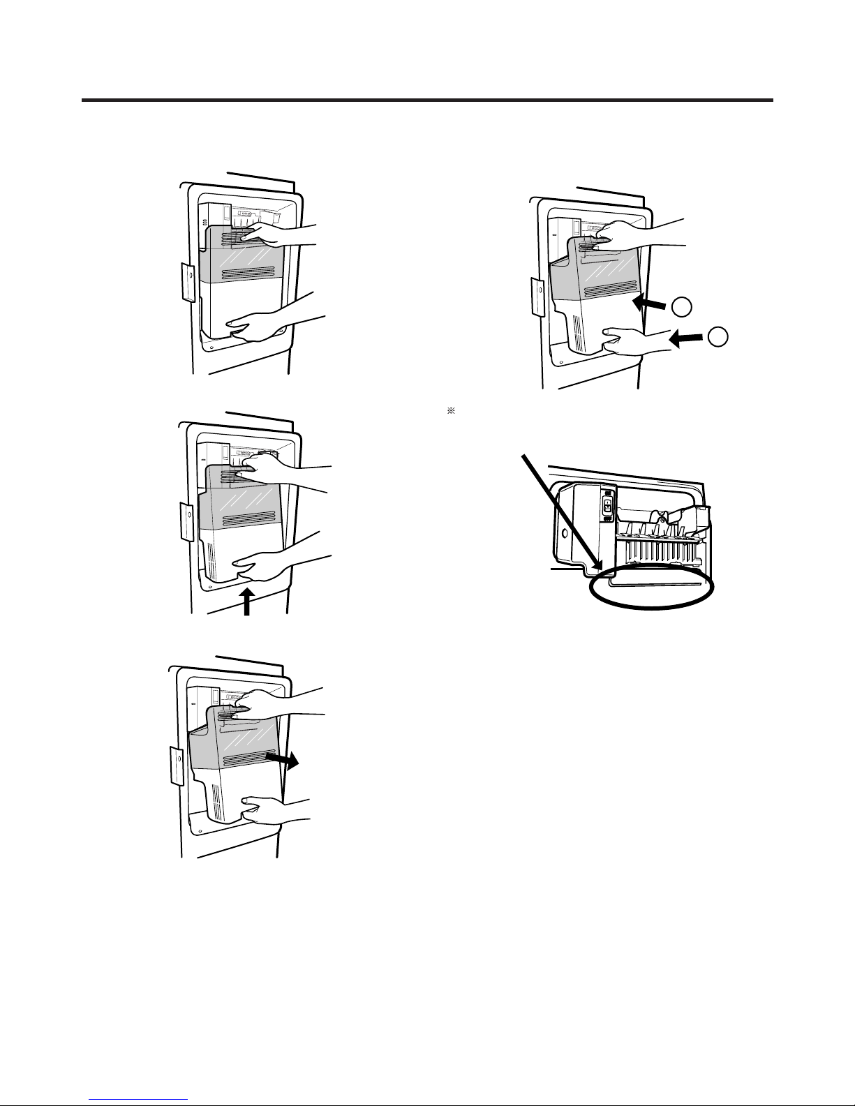
3-20 HOW TO REMOVE A DOOR ICE BIN
1) Grip the handles, as shown in the picture.
2) Lift the lower part slightly.
3) Take the Ice Bin out slowly.
3-21 HOW TO INSERT A DOOR ICE BIN
1) Insert the Ice Bin, slightly tilting it to avoid touching the
Icemaker. (especially, ice maker lever)
Insert the ice bucket carefully avoid contacting the
automatic shut off arm.
- 13 -
1
2
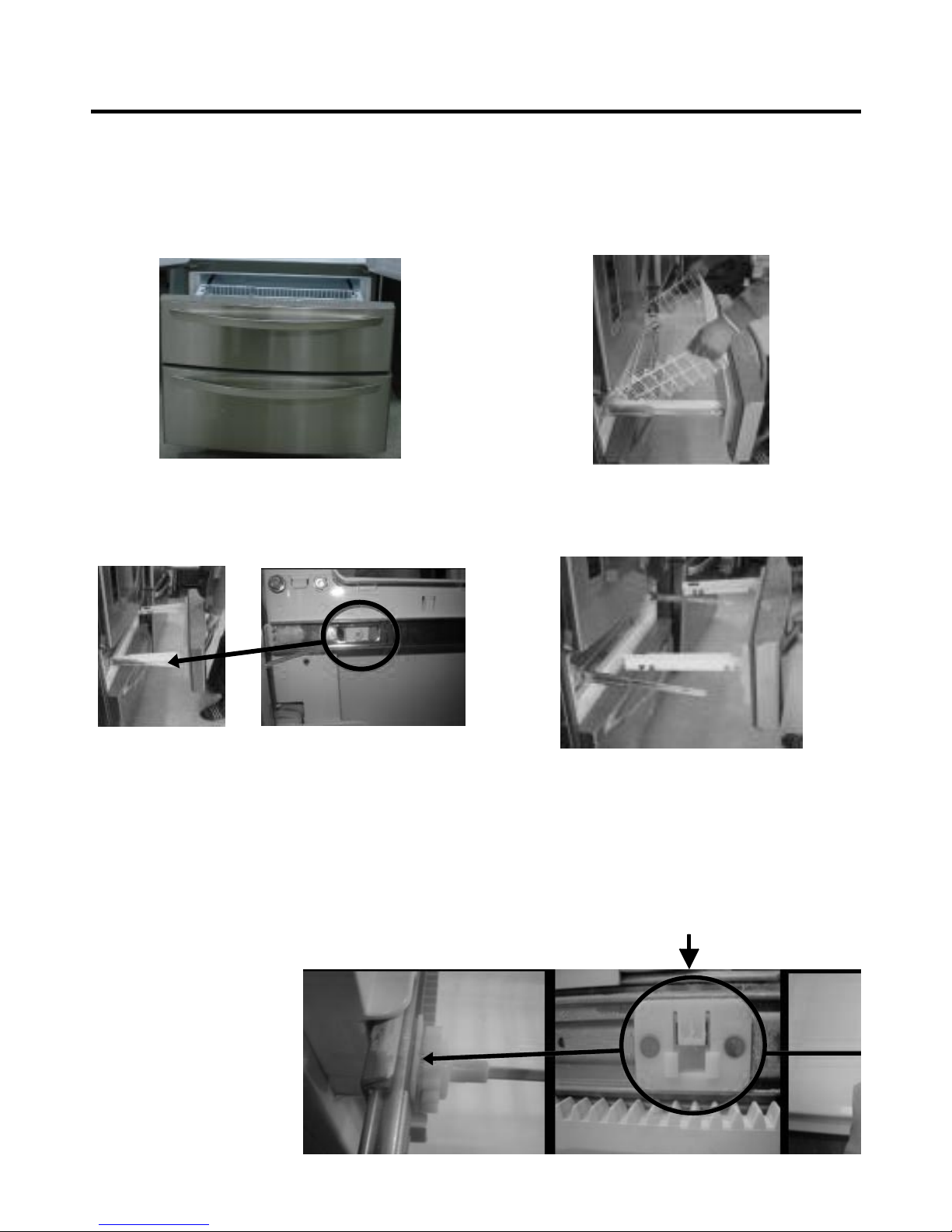
3-22 HOW TO REMOVE AND REINSTALL THE PULLOUT DRAWER
3-22-1 Follow Steps to Remove
Step 1) Open the freezer door.
Step 3) Remove the two screws from the guide rails (one
from each side).
Step 2) Remove the lower basket.
Step 4) Lift the freezer door up to unhook it from the rail
support and remove.
Pull both rails to full extension.
Step 5) First: Remove the gear from the left side first by releasing the tab behind the gear, place a screwdriver between the
gear and the tab and pull up on the gear.
Second: Remove the center rail.
Third: Remove the gear from the right side by following the same steps for the left side.
NOTE: THIS TAB MUST BE PUSHED IN TO RELEASE THE GEAR.
- 14 -
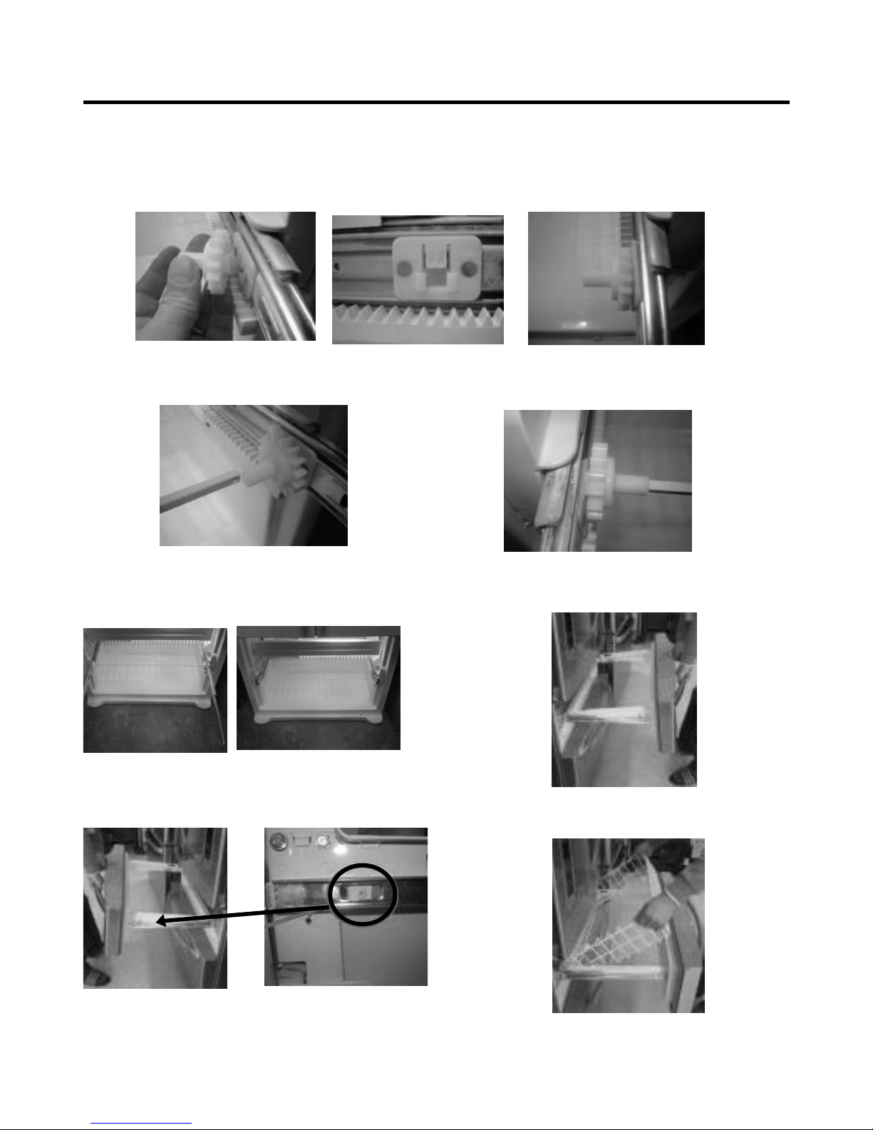
3-22-2 Follow Steps to Reinstall
Step 1) Reinstall the right side gear into the clip.
Step 2) Insert the rail into the right side gear. Gears do not
need to be perpendicular to each other.
Step 4) The rail system will align itself by pushing the rails
all the way into the freezer section.
Pull the rails back out to full extension.
Step 6) Reinstall the two screws into the guide rails
(one from each side).
Step 3) Insert the rail into the left side gear, and insert the
gear into the clip.
Step 5) Reinstall the freezer door by inserting the rail tabs
into the guide rail.
Step 7) Reinstall the lower basket, and close the freezer
door.
- 15 -
3-23. WATER VALVE DISASSEMBLY METHOD
1) Turn off the water. Then separate the water line from the
valve.
2). Separate the Mechanical Cover and Valve Screw.
3) Separate the housing and pull out the valve.
4) Lay a dry towel on the floor and get ready to spill water
from the water filter. Pull out the Cilp. Then press te
collet to separate the tube from the connector and pour
out the water until emptied.
3-24. FAN AND FAN MOTOR DISASSEMBLY
METHOD
1) Using a short screwdriver, loosen one SCREW in
DRAIN PIPE ASSEMBLY and one connected to the
MOTOR COVER.
2) Pull and separate the FAN ASSEMBLY and MOTOR
turning counterclockwise based on the MOTOR SHAFT.
The assembly is in the reverse order of the disassembly
and take special care for the following details.
1. Be careful not to bend the tube during assembly.
2. Press the WATER DISPENSER button until water pours
out and check for leakage in the CONNECTOR TUBE (It
differs by the water pressure but usually takes about 2
minutes until water pours out.)
Mechanical Cover
Housing
→
→
MOTOR COVER
FAN ASSEMBLY MOTOR
- 16 -

3-25 TOP DRAWER
To remove the freezer drawer, pull the drawer open to full extension. Remove the drawer and Ice Bin lifting the basket from
the rail system.
3-26 BOTTOM DRAWER
To remove the freezer drawer, pull the drawer open to full extension. Remove the lower DuraBase ®basket by lifting the
basket from the rail system.
- 17 -
4. ADJUSTMENT
4-1 COMPRESSOR
4-1-1 Role
The compressor intakes low temperature and low pressure
gas from the evaporator of the refrigerator and compresses
this gas to high-temperature and high-pressure gas. It then
delivers the gas to the condenser.
4-1-2 Composition
The compressor includes overload protection. The PTC
starter and OLP (overload protector) are attached to the
outside of the compressor. Since the compressor is
manufactured to tolerances of 1 micron and is hermetically
sealed in a dust and moisture-free environment, use
extreme caution when repairing it.
4-1-3 Note for usage
(1) Be careful not to allow over-voltage and over-current.
(2) If compressor is dropped or handled carelessly, poor
operation and noise may result.
(3) Use proper electric components appropriate to the
particular compressor in your product.
(4) Keep compressor dry.
If the compressor gets wet (in the rain or a damp
environment) and rust forms in the pin of the Hermetic
Terminal, poor operation and contact may result.
If the hermetic connector rusts out or fails, refrigerant
and oil will be expelled into the contact area, probably
resulting in smoke and fire.
(5) When replacing the compressor, be careful that dust,
humidity, and soldering flux don’t contaminate the inside
of the compressor. Contamination in the cylinder may
cause noise, improper operation or even cause it to
lock up.
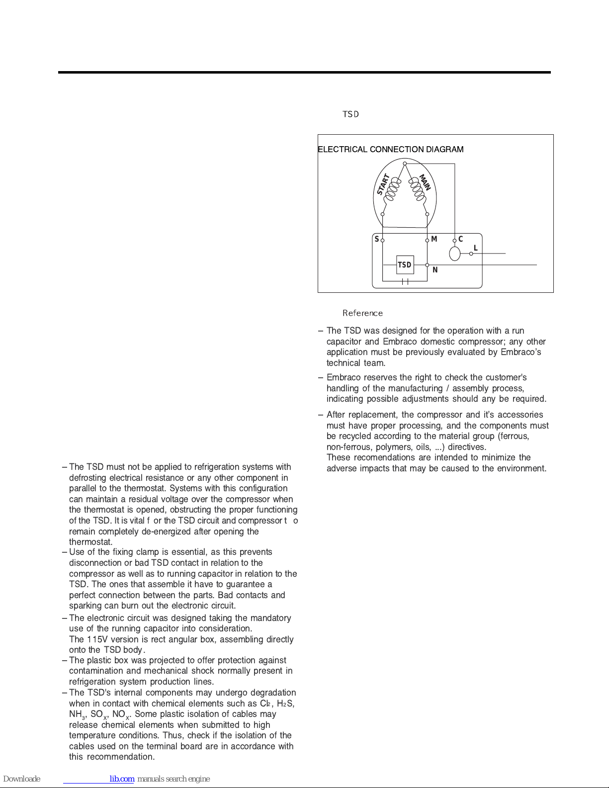
4-2 TSD STARTER
4-2-3
-Applied circuit diagram
● Starting method for the motor
4-2-4
ELECTRICAL AND DIMENSION DIAGRAM
ELECTRICAL CONNECTION DIAGRAM
SM
TSD
START
MAIN
N
C
L
Ð The TSD must not be applied to refrigeration systems with
defrosting electrical resistance or any other component in
parallel to the thermostat. Systems with this configuration
can maintain a residual voltage over the compressor when
the thermostat is opened, obstructing the proper functioning
of the TSD. It is vital f or the TSD circuit and compressor t o
remain completely de-energized after opening the
thermostat.
Ð Use of the fixing clamp is essential, as this prevents
disconnection or bad TSD contact in relation to the
compressor as well as to running capacitor in relation to the
TSD. The ones that assemble it have to guarantee a
perfect connection between the parts. Bad contacts and
sparking can burn out the electronic circuit.
Ð The electronic circuit was designed taking the mandatory
use of the running capacitor into consideration.
The 115V version is rect angular box, assembling directly
onto the TSD body .
Ð The plastic box was projected to offer protection against
contamination and mechanical shock normally present in
refrigeration system production lines.
Ð The TSD's internal components may undergo degradation
when in contact with chemical elements such as CI
2
,H2S,
NH
3
,SOX,NOX. Some plastic isolation of cables may
release chemical elements when submitted to high
temperature conditions. Thus, check if the isolation of the
cables used on the terminal board are in accordance with
this recommendation.
Ð
The TSD was designed for the operation with a run
capacitor and Embraco domestic compressor; any other
application must be previously evaluated by EmbracoÕs
technical team.
Ð
Embraco reserves the right to check the customer's
handling of the manufacturing / assembly process,
indicating possible adjustments should any be required.
Ð
After replacement, the compressor and itÕs accessories
must have proper processing, and the components must
be recycled according to the material group (ferrous,
non-ferrous, polymers, oils, ...) directives.
These recomendations are intended to minimize the
adverse impacts that may be caused to the environment.
- 19 -
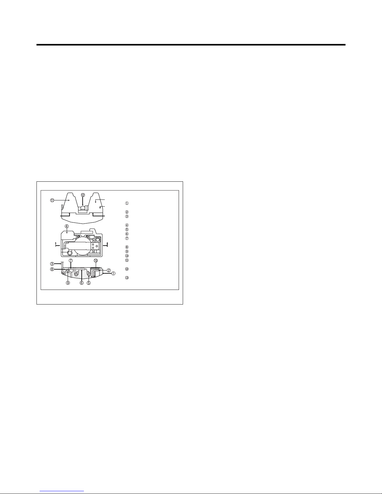
4-3 OLP (OVERLOAD PROTECTOR)
4-3-1 Definition of OLP
(1) OLP (OVERLOAD PROTECTOR) is attached to the
Compressor and protects the Motor by opening the
circuit to the Motor if the temperature rises and
activating the bimetal spring in the OLP.
(2) When high current flows to the Compressor motor, the
Bimetal works by heating the heater inside the OLP,
and the OLP protects the Motor by cutting off the
current flowing to the Compressor Motor.
4-3-2 Role of the OLP
(1) The OLP is attached to the Sealed Compressor used
for the Refrigerator. It prevents the Motor Coil from
being started in the Compressor.
(2) For normal operation of the OLP, do not turn the Adjust
Screw of the OLP in any way.
Part
Customer part
number
Lot code/
date code
330 FBYY -S1 BOX98
12345678
Physical
termination
part number
Electrical
characteristics
part number
No. Name
Base, phenolic
(UL 94 V-0 rated)
Movable arm support, plated steel
Stationary contact support,
plated steel
Heater support, plated steel
Heater, resistance alloy
Disc, thermostatic alloy
Movable arm, spring temper
copper alloy
Contact, movable, silver on copper
Contact, stationary, silver on copper
Slug, plated steel
Cover, polyester
(UL 94 V -0 rated)
Pin connector, plated copper alloy
(To engage 2.33/2.66 mm dia. pin)
Quick-connect terminal, brass,
conforms to UL 310, MEMA
DC-2, DIN 46344
(OVERLOAD PROTECTOR cross section)
Figure 19
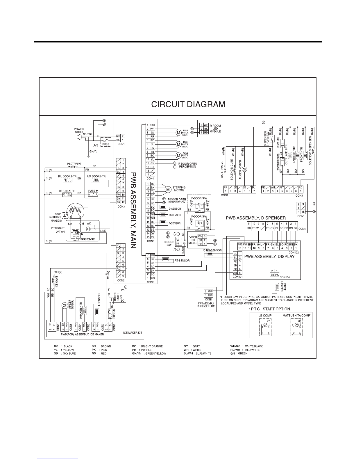
5. CIRCUIT DIAGRAM
- 20 -
- 21 -
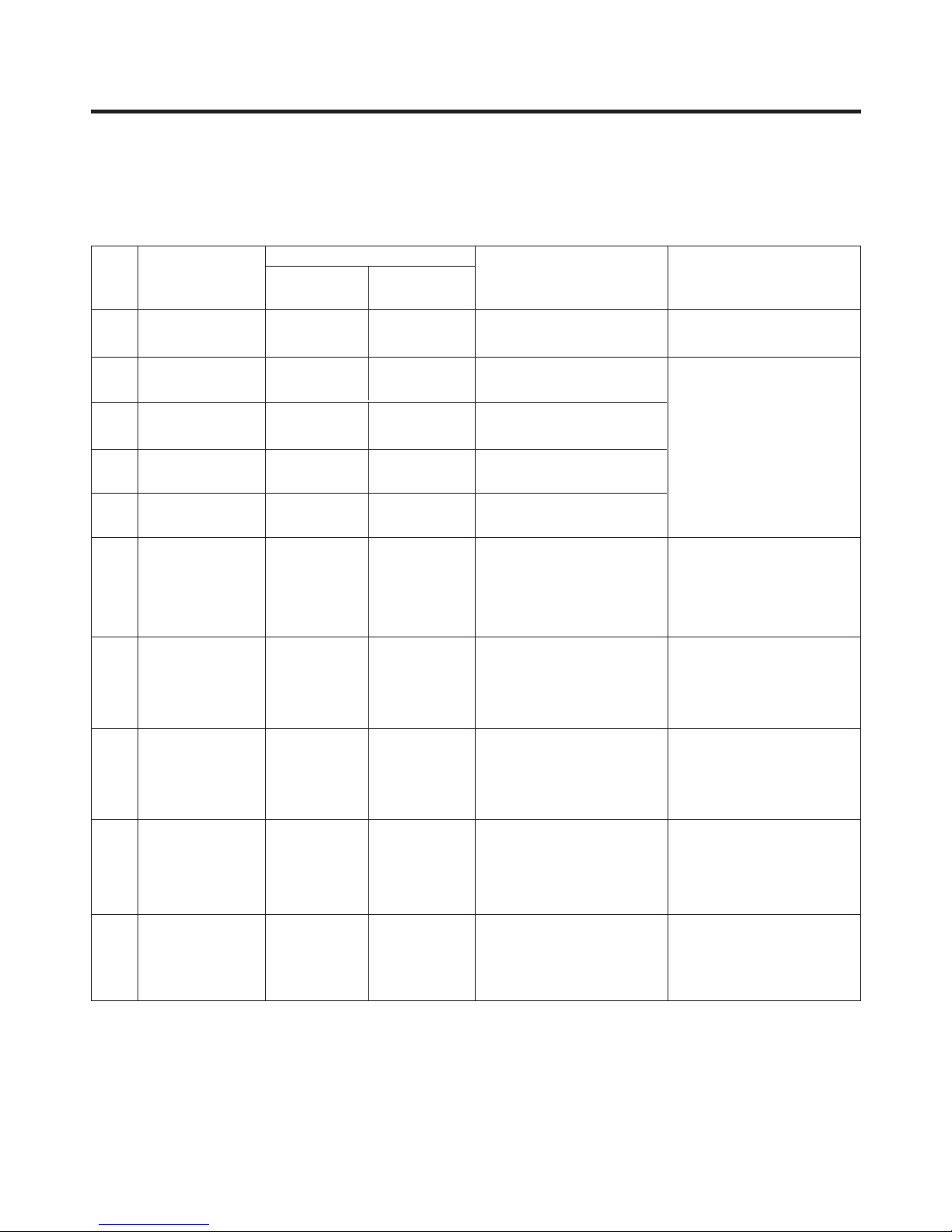
6-1. Error Code Summary
ww
WARNING : When you check the Resistance values, be sure to turn off the power.
And wait for the voltage-discharge sufficiently.
6. TROUBLESHOOTING
1
2
3
4
5
6
7
8
9
10
Normality
Freezer Sensor
Error
Refrigerator
Sensor Error
Defrosting
Sensor Error
Icing Sensor
Error
Poor Defrosting
Abnormality of
BLDC FAN Motor
for Ice Making
Abnormality of
BLDC FAN Motor
for Freezer
Abnormality of
BLDC FAN Motor
for Mechanic Room
Communication
Error
None
Short or Disconnection
of Freezer Sensor
Short or Disconnection
of Refrigerator Sensor
Short or Disconnection
of Defrosting Sensor
Short or Disconnection
of Icing Sensor
Even though it is passed
1 hour since then
Defrosting , if Defrosting
sensor is not over 8°C, it
is caused
It is caused when
feedback signal isn’ t
over 65
seconds during BLDC
FAN motor operating
It is caused when
feedback
signal isn ’ t over 65
seconds during BLDC
FAN motor operating
Communication Error
between Micom of Main
PCB and Display Micom
It is caused when
feedback
signal isn’ t over 65
seconds during BLDC
FAN motor operating
Normal operation of Display
Check each sensor and its
connector.
Temperature Fuse
Disconnection, Heater
disconnection, DRAIN Jam,
Poor Relay for Heater
Poor BLDC Motor
connection, DRIVE IC,
and TR
Poor BLDC Motor
connection, DRIVE IC,
and TR
Poor BLDC Motor
connection, DRIVE IC,
and TR
Poor Communication
connection,Poor TR of
Transmitter and Receiver
Tx/Rx between display
and main board.
Er
Er
Er
Er
Er
Er
Er
Er
Er
FS
rS
dS
IS
dH
IF
FF
CF
CO
NO
Error Detection
Category
Error Generation Factors Remark
Freezer
Temperature
Ref.
Temperature
Error Display
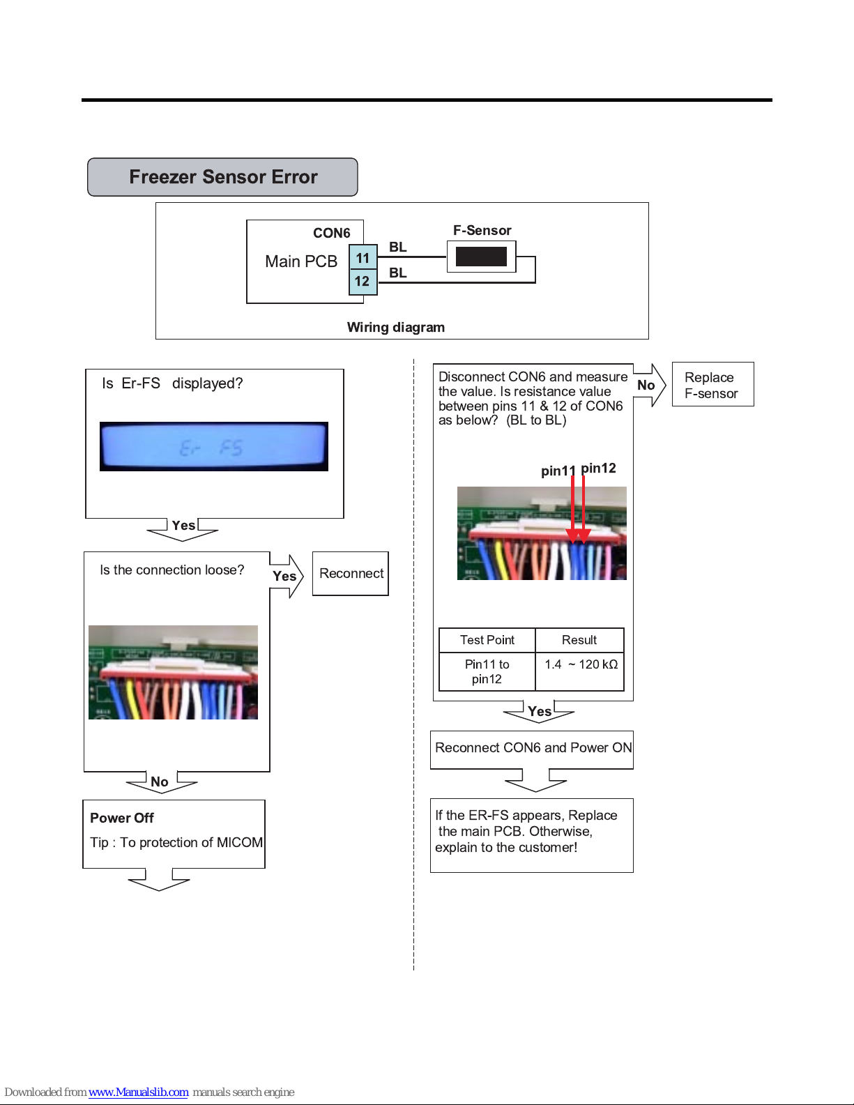
6-2. Troubleshooting With Error
- 22 -
Disconnect CON6 and measure
the value. Is resistance value
between pins 11 & 12 of CON6
as below? (BL to BL)
Freezer Sensor Error
Is the connection loose?
Main PCB
BL
BL
F-Sensor
CON6
11
12
If the ER-FS appears, Replace
the main PCB. Otherwise,
explain to the customer!
Replace
F-sensor
No
pin12
pin11
Wiring diagram
Yes
1.4 ~ 120 k½Pin11 to
pin12
ResultTest Point
Reconnect
Reconnect CON6 and Power ON
Power Off
Tip : To protection of MICOM
No
Yes
Is Er-FS displayed?
Yes
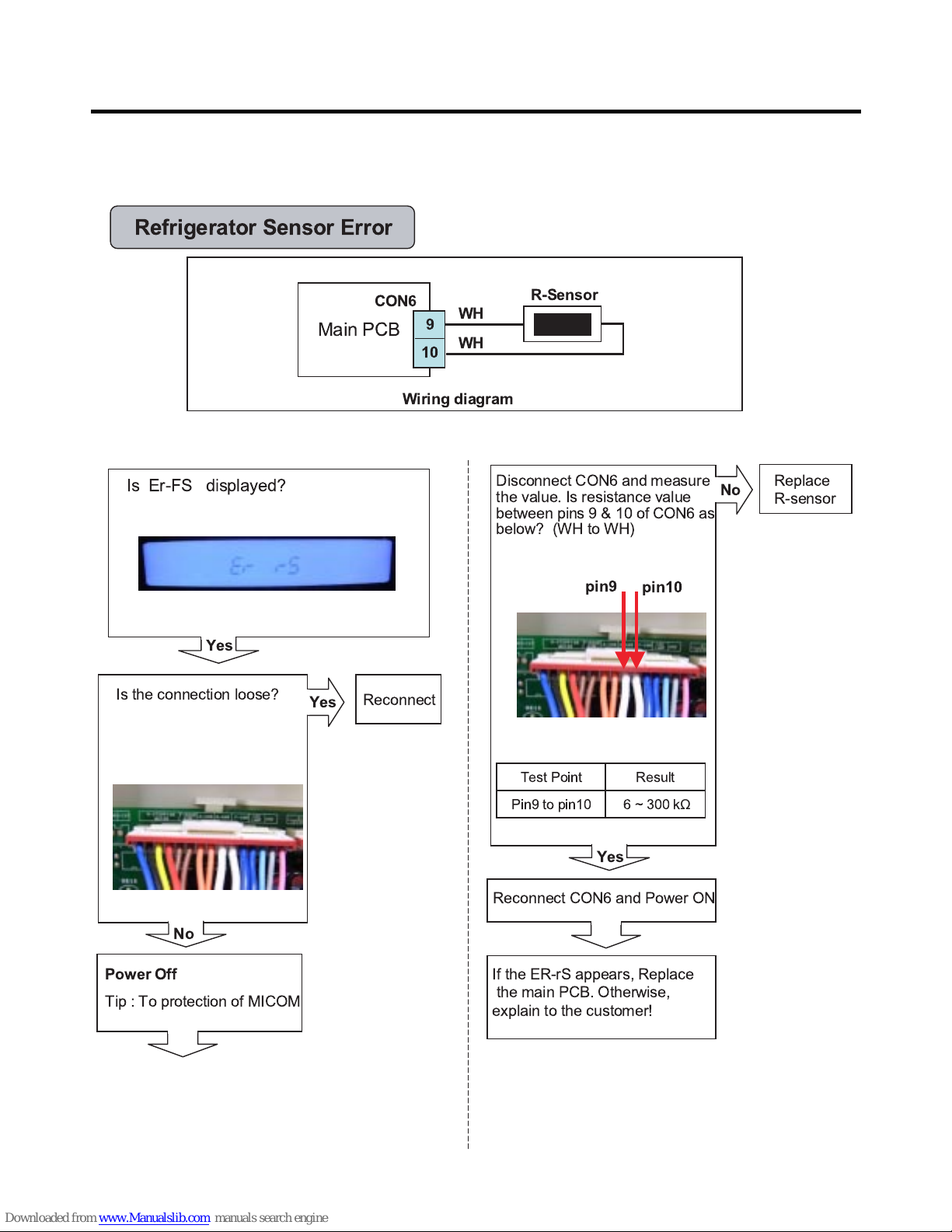
- 23 -
Main PCB
WH
WH
R-Sensor
CON6
9
10
Refrigerator Sensor Error
Wiring diagram
Disconnect CON6 and measure
the value. Is resistance value
between pins9&10ofCON6 as
below? (WH to WH)
Is the connection loose?
If the ER-rS appears, Replace
the main PCB. Otherwise,
explain to the customer!
Replace
R-sensor
No
pin10
pin9
Yes
6~300kΩ
Pin9 to pin10
ResultTest Point
Reconnect
Reconnect CON6 and Power ON
Power Off
Tip : To protection of MICOM
No
Yes
Is Er-FS displayed?
Yes
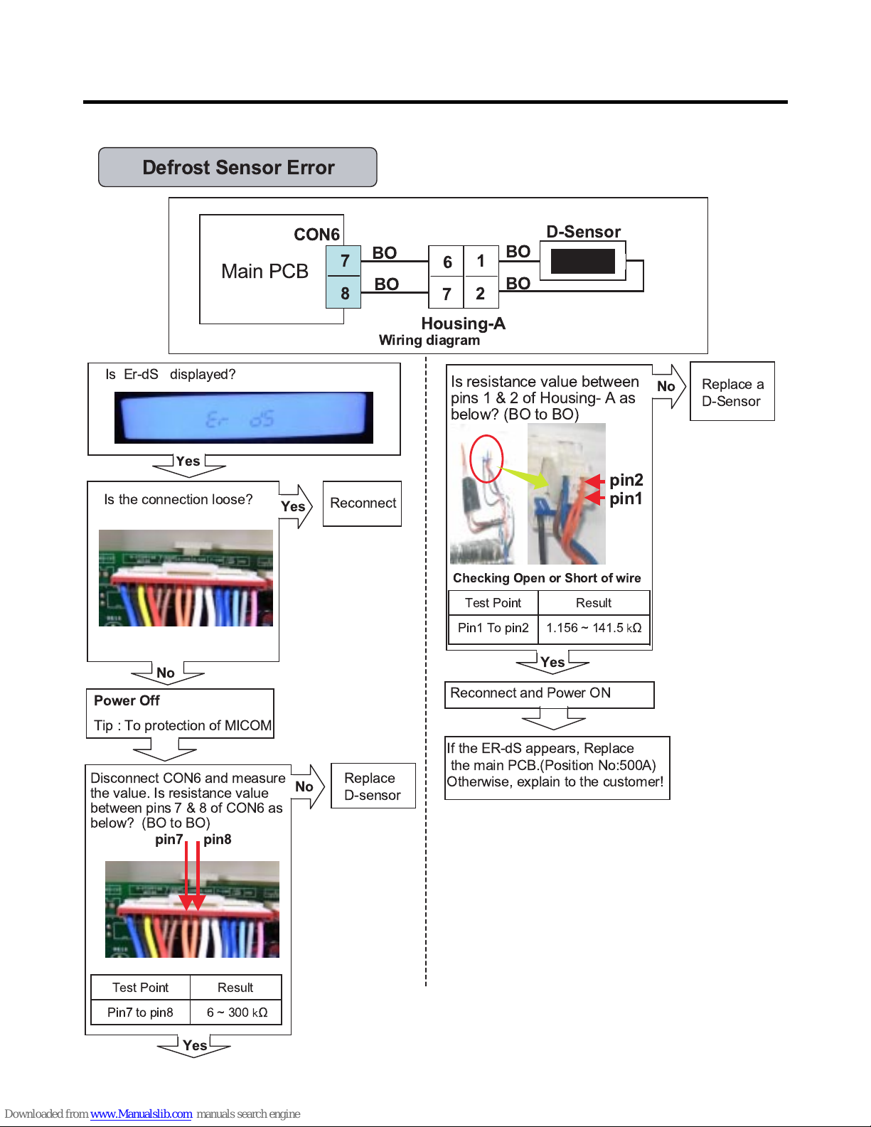
- 24 -
Housing-A
Main PCB
BO
BO
BO
BO
D-Sensor
7
8
2
1
CON6
7
6
Defrost Sensor Error
Wiring diagram
Is Er-dS displayed?
Disconnect CON6 and measure
the value. Is resistance value
between pins 7&8ofCON6as
below? (BO to BO)
Yes
Is the connection loose?
If the ER-dS appears, Replace
the main PCB.(Position No:500A)
Otherwise, explain to the customer!
Replace
D-sensor
No
pin8
pin7
Yes
6~300 ½Pin7 to pin8
ResultTest Point
Reconnect
Reconnect and Power ON
Power Off
Tip : To protection of MICOM
No
Yes
Is resistance value between
pins 1 & 2 of Housing- A as
below? (BO to BO)
Replace a
D-Sensor
pin1
pin2
1.156 ~ 141.5 ½Pin1 To pin2
ResultTest Point
Checking Open or Short of wire
No
Yes
- 25 -
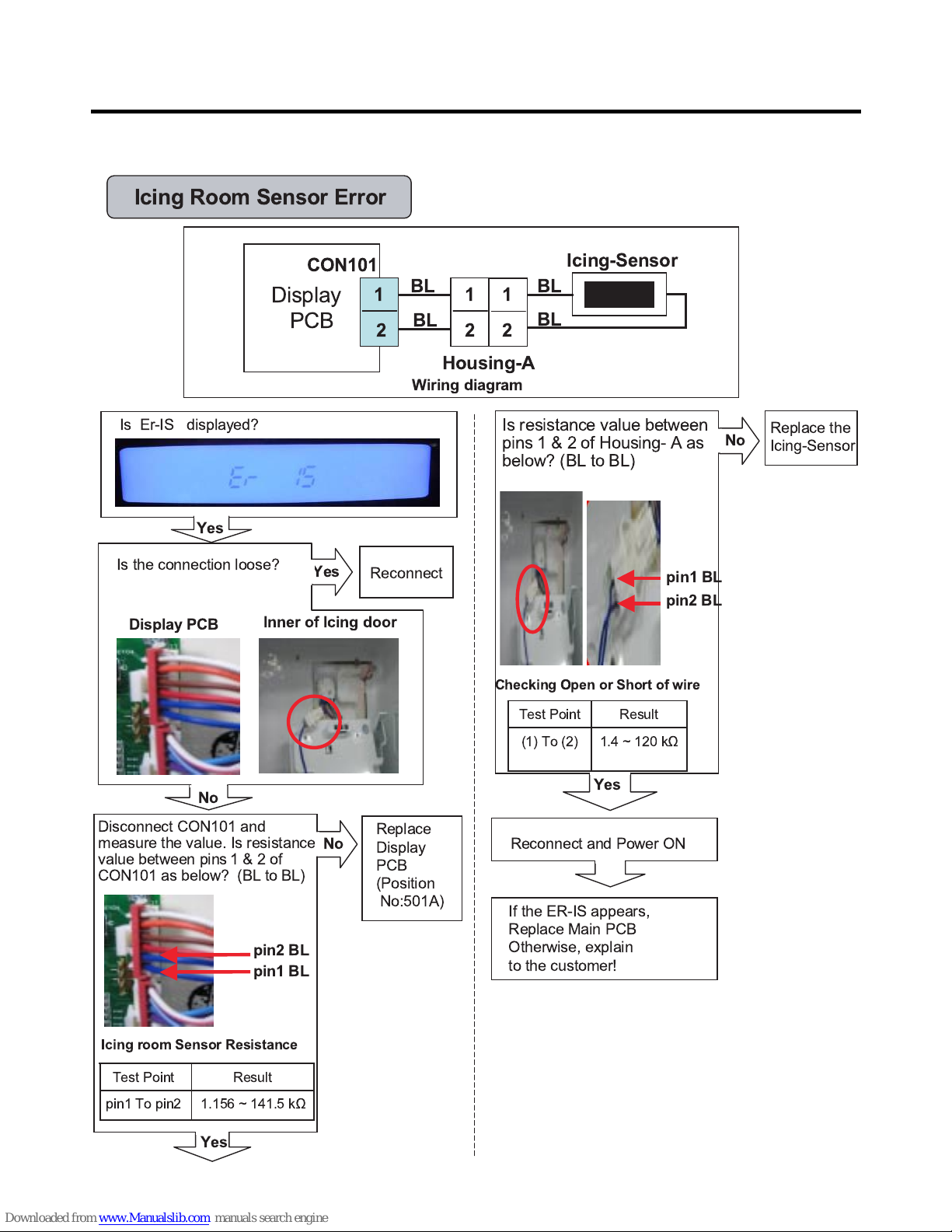
Housing-A
Display
PCB
BL
BL
BL
BL
Icing-Sensor
CON101
1
2
1
2
1
2
Icing Room Sensor Error
Wiring diagram
Is Er-IS displayed?
Yes
Yes
No
Is the connection loose?
Reconnect
pin1 BL
pin2 BL
1.156 ~ 141.5 k½pin1 To pin2
ResultTest Point
Icing room Sensor Resistance
Replace the
Icing-Sensor
Yes
1.4 ~ 120 k½(1) To (2)
ResultTest Point
Checking Open or Short of wire
pin2 BL
pin1 BL
Replace
Display
PCB
(Position
No:501A)
If the ER-IS appears,
Replace Main PCB
Otherwise, explain
to the customer!
Reconnect and Power ON
Display PCB
Inner of Icing door
Yes
Disconnect CON101 and
measure the value. Is resistance
value between pins 1&2of
CON101 as below? (BL to BL)
No
Is resistance value between
pins 1 & 2 of Housing- A as
below? (BL to BL)
No
- 26 -
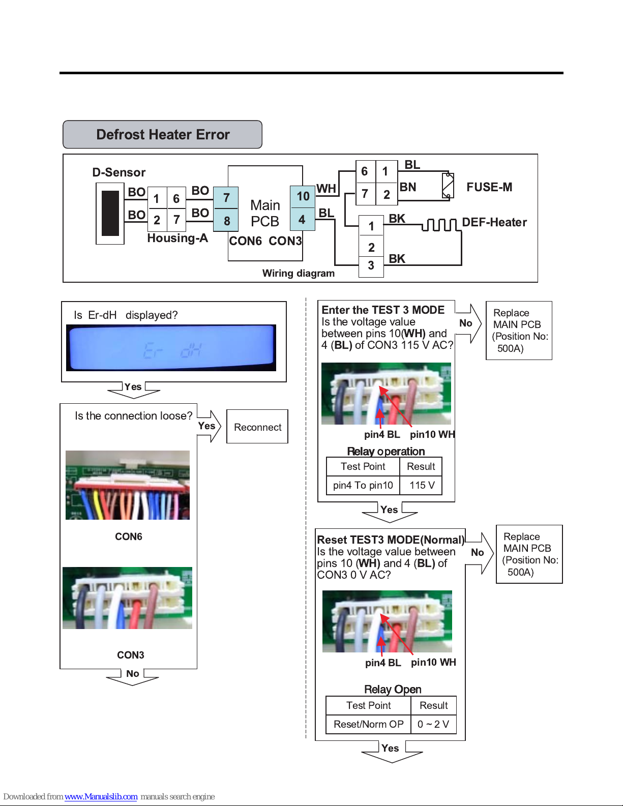
Enter the TEST 3 MODE
Is the voltage value
between pins 10(
WH)
and
4(
BL)
of CON3 115 V AC?
Is Er-dH displayed?
Yes
CON6
CON3
Replace
MAIN PCB
Yes
No
Main
PCB
WH
BL
FUSE-M
CON3
10
4
DEF-Heater
Housing-A
BO
D-Sensor
7
8
BO
2
CON6
BO
BO
7
6
BL
BN
BK
2
1
7
6
1
3
1
2
BK
Is the connection loose?
pin4 BL
pin10 WH
No
Yes
115 Vpin4 To pin10
ResultTest Point
Reset TEST3 MODE(Normal)
Is the voltage value between
pins 10 (
WH)
and 4 (
BL)
of
CON3 0 V AC?
No
Yes
0~2VReset/Norm OP
ResultTest Point
Defrost Heater Error
Wiring diagram
Relay Open
Relay OpenRelay Open
Relay Open
Reconnect
Relay o peration
Relay o perationRelay o peration
Relay o peration
pin4 BL
pin10 WH
(Position No:
500A)
Replace
MAIN PCB
(Position No:
500A)
- 27 -
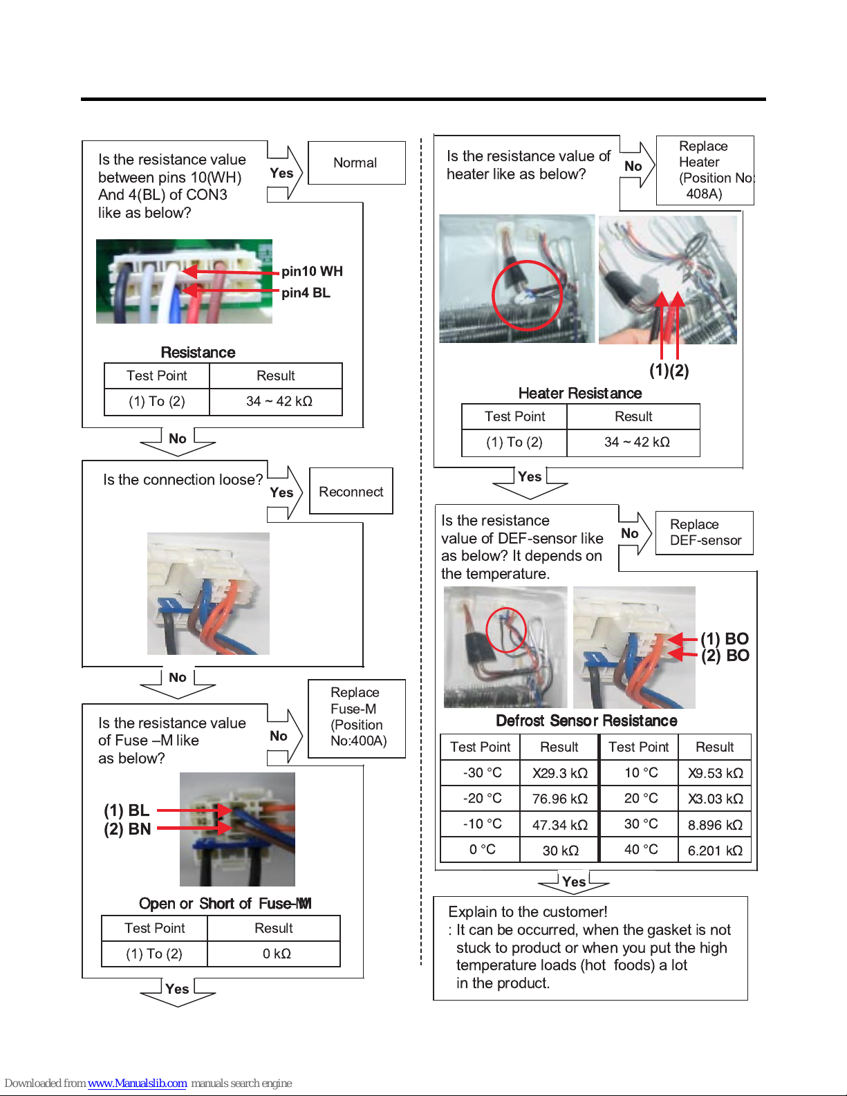
Explain to the customer!
: It can be occurred, when the gasket is not
stuck to product or when you put the high
temperature loads (hot foods) a lot
in the product.
Normal
Is the resistance value
between pins 10(WH)
And 4(BL) of CON3
like as below?
Replace
DEF-sensor
No
Yes
Yes
No
Yes
34~42k½(1) To (2)
ResultTest Point
Is the resistance value of
heater like as below?
(2)
(1)
Replace
Heater
(Position No:
408A)
0¡C
-10 ¡C
-20 ¡C
-30 ¡C
Test Point
30 k½
47.34 k½
76.96 k½
X29.3 k½
Result
X9.53 k½
10 ¡C
X3.03 k½
20 ¡C
8.896 k½
30 ¡C
6.201 k½
40 ¡C
ResultTest Point
(2) BO
(1) BO
Heater Resistance
Heater ResistanceHeater Resistance
Heater Resistance
No
Defrost Sensor Resistance
Defrost Sensor ResistanceDefrost Sensor Resistance
Defrost Sensor Resistance
Is the resistance
value of DEF-sensor like
as below? It depends on
the temperature.
Replace
Fuse-M
(Position
No:400A)
Is the resistance value
of Fuse ÐM like
as below?
No
(2) BN
(1) BL
0k½(1) To (2)
ResultTest Point
Open or Short of Fuse
Open or Short of FuseOpen or Short of Fuse
Open or Short of Fuse----MMMM
Yes
pin4 BL
pin10 WH
34~42k½(1) To (2)
ResultTest Point
Resistance
ResistanceResistance
Resistance
Yes
No
Is the connection loose?
Reconnect
- 28 -
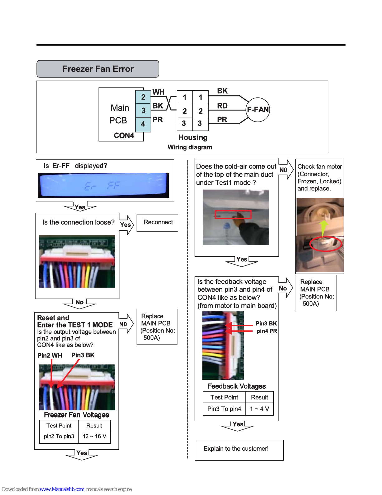
Is Er-FF displayed?
Yes
Is the connection loose?
Reconnect
Housing
Main
PCB
WH
CON4
2
3
4
1
2
3
BK
PR
F-FAN
1
2
3
BK
RD
PR
Check fan motor
(Connector,
Frozen, Locked)
and replace.
No
Yes
Is the feedback voltage
between pin3 and pin4 of
CON4 like as below?
(from motor to main board)
N0
Yes
No
pin4 PR
Pin3 BK
1~4VPin3 To pin4
ResultTest Point
Wiring diagram
Feedback
FeedbackFeedback
FVoltages
Voltagesltages
ltages
Yes
Freezer Fan Error
N0
12 ~ 16 Vpin2 To pin3
ResultTest Point
Pin3 BK
Pin2 WH
Freezer Fan Voltages
Freezer Fan VoltagesFreezer Fan Voltages
Freezer Fan Voltages
Yes
Reset and
Enter the TEST 1 MODE
Is the output voltage between
pin2 and pin3 of
CON4 like as below?
Does thecold-air come out
of the top of the main duct
under Test1 mode ?
Explain to the customer!
Replace
MAIN PCB
(Position No:
500A)
Replace
MAIN PCB
(Position No:
500A)
Is Er-FF displayed?
Yes
Is the connection loose?
Reconnect
Housing
Main
PCB
WH
CON4
2
3
4
1
2
3
BK
PR
F-FAN
1
2
3
BK
RD
PR
Check fan motor
(Connector,
Frozen, Locked)
and replace.
No
Yes
Is the feedback voltage
between pin3 and pin4 of
CON4 like as below?
(from motor to main board)
N0
Yes
No
pin4 PR
Pin3 BK
1~4VPin3 To pin4
ResultTest Point
Wiring diagram
Fee k
Fee kFee k
Fltages
ltagesltages
ltages
Yes
Freezer Fan Error
N0
12 ~ 16 Vpin2 To pin3
ResultTest Point
Pin3 BK
Pin2 WH
Freezer Fan Voltages
Freezer Fan VoltagesFreezer Fan Voltages
Freezer Fan Voltages
Yes
Reset and
Enter the TEST 1 MODE
Is the output voltage between
pin2 and pin3 of
CON4 like as below?
Does thecold-air come out
of the top of the main duct
under Test1 mode ?
Explain to the customer!
Replace
MAIN PCB
(Position No:
500A)
Replace
MAIN PCB
(Position No:
500A)
- 29 -
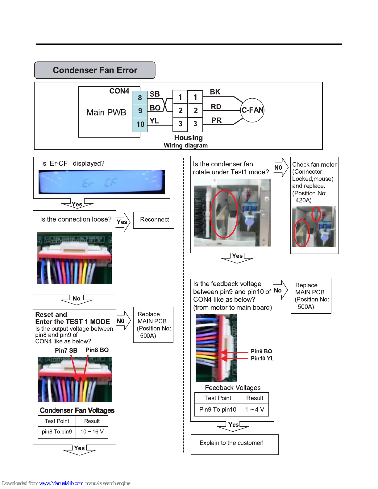
Housing
Main PWB
SB
CON4
8
9
10
1
2
3
BO
YL
C-FAN
1
2
3
BK
RD
PR
Condenser Fan Error
Wiring diagram
Is Er-CF displayed?
Yes
Is the connection loose?
Reconnect
No
Yes
Is the feedback voltage
between pin9 and pin10 of
CON4 like as below?
(from motor to main board)
Yes
No
1~4VPin9 To pin10
ResultTest Point
Feedback Voltages
N0
10 ~ 16 Vpin8 To pin9
ResultTest Point
Pin8 BO
Pin7 SB
Condenser
CondenserCondenser
Condenser Fan Voltages
Fan VoltagesFan Voltages
Fan Voltages
Yes
Reset and
Enter the TEST 1 MODE
Is the output voltage between
pin8 and pin9 of
CON4 like as below?
Explain to the customer!
Check fan motor
(Connector,
Locked,mouse)
and replace.
(Position No:
420A)
N0
Yes
Is the condenser fan
rotate under Test1 mode?
Replace
MAIN PCB
(Position No:
500A)
Replace
MAIN PCB
(Position No:
500A)
Pin10 YL
Pin9 BO
 Loading...