

Kenmore 795.78546800, 795.78543800, 795.78552800, 795.78544800, 795.78553800 Service Manual
...
CAUTION
BEFORE SERVICING THE UNIT,
READ THE SAFETY PRECAUTIONS IN THIS MANUAL.
REFRIGERATOR
SERVICE MANUAL
R
795.78542800
795.78543800
795.78544800
795.78546800
795.78549800
795.78552800
795.78553800
795.78554800
795.78556800
795.78559800
795.78712800
795.78713800
795.78719800
795.78722800
795.78723800
795.78729800
P/No. MFL47912401 (Last Revision: March. 10. 2008)
Model #s:

- 2 -
SAFETY PRECAUTIONS....................................................................................................................................................... 2
1. SPECIFICATIONS............................................................................................................................................................... 3
2. PARTS IDENTIFICATION................................................................................................................................................... 4
3. DISASSEMBLY.............................................................................................................................................................. 5-12
DOOR.............................................................................................................................................................................. 5-8
TO REMOVE THE DISPENSER .........................................................................................................................................8
FAN AND FAN MOTOR...................................................................................................................................................... 8
DEFROST CONTROL ASSEMBLY.................................................................................................................................... 9
LAMP.................................................................................................................................................................................. 9
CONTROL BOX-REFRIGERATOR.................................................................................................................................... 9
MULTI DUCT...................................................................................................................................................................... 9
HOW TO REMOVE AND REINSTALL THE PULLOUT DRAWER.............................................................................. 10-15
4. ADJUSTMENT............................................................................................................................................................. 16-18
COMPRESSOR................................................................................................................................................................ 16
PTC-STARTER................................................................................................................................................................. 16
OLP (OVERLOAD PROTECTOR).................................................................................................................................... 17
TO REMOVE THE COVER PTC.......................................................................................................................................17
5. CIRCUIT DIAGRAM.......................................................................................................................................................... 18
6. TROUBLESHOOTING................................................................................................................................................. 19-23
COMPRESSOR AND ELECTRIC COMPONENTS.......................................................................................................... 19
PTC AND OLP.................................................................................................................................................................. 21
OTHER ELECTRICAL COMPONENTS ........................................................................................................................... 21
SERVICE DIAGNOSIS CHART........................................................................................................................................ 22
REFRIGERATION CYCLE.......................................................................................................................................... 26-27
7. OPERATION PRINCIPLE & REPAIR METHOD OF ICEMAKER .............................................................................. 25-28
8. DESCRIPTION OF FUNCTION & CIRCUIT OF MICOM ........................................................................................... 29-40
CONTENTS
Please read the following instructions before servicing your refrigerator.
1. Unplug the power before handling any elctrical componets.
2. Check the rated current, voltage, and capacity.
3. Take caution not to get water near any electrical components.
4. Use exact replacement parts.
5. Remove any objects from the top prior to tilting the product.
SAFETY PRECAUTIONS
1-1 DISCONNECT POWER CORD BEFORE
SERVICING
IMPORTANT – RECONNECT ALL
GROUNDING DEVICES
All parts of this appliance capable of conducting electrical
current are grounded. If grounding wires, screws, straps,
clips, nuts or washers used to complete a path to ground
are removed for service, they must be returned to their
original position and properly fastened.
1-2 IMPORTANT NOTICE
This information is intended for use by individuals
possessing adequate backgrounds of electrical, electronic
and mechanical experience. Any attempt to repair a major
appliance may result in personal injury and property
damage. The manufacturer or seller cannot be responsible
for the interpretation of this information, nor can it assume
any liability in connection with its use.
1-3 ELECTRICAL SPECIFICATIONS
Temperature Control (Freezer Compartment)...-6°F to +8°F
Defrost Control.................Total Comp Running Time : 7 hrs
Defrost Thermostat.......................................................46°F
Electrical Rating : 115VAC, 60Hz.................................1-5 A
Maximum Current Leakage.......................................0.5 mA
Maximum Ground Path Resistance....................0.14 Ohms
Energy Consumption .....21 cu.ft. 484 kWh/yr (Energy Star)
.......................................25 cu.ft. 499 kWh/yr (Energy Star)
1-4 NO LOAD PERFORMANCE
CONTROL POSITION: MID/MID
And Ambient of: ..................70°F..................................90°F
Fresh Food, °F....................33°F to 41°F.........33°F to 41°F
Frozen Food, °F..................-4°F to +4°F..........-4°F to +4°F
Percent Running Time........35%-45%.................50°F-70°F
1-5 REFRIGERA TION SYSTEM
Minimum Compressor Capacity Vacuum ............... 20 MIN.
Minimum Equalized Pressure
@ 70°F ....................................................... 49 PSIG
@ 90°F ....................................................... 56 PSIG
Refrigerant R134a ................................................. 4.06 oz.
Compressor ..................................................... 830 BTU/hr
1-6 INSTALLATION
Clearance must be provided at top, sides and rear of the
refrigerator for air circulation.
AT TOP ......................................................................... 1 in
AT SIDES ...................................................................... 1 in
AT REAR ...................................................................... 2 in
1-7 REPLACEMENT PARTS
Relay............................................................. 6748C-0004D
Overload ....................................................... 6750C-0005P
Defrost Thermostat ...................................... 6615JB2005H
Defrost Heater ............................................. 5300JK1005D
Evaporator Fan Motor ......... 4681JK1004D(4681JK1004A)
Capacitor .............................. 0CZZJB2014G(Combo PTC)
Compressor (Hi-Side) .................................. 2521C-A5719
Evaporator (Lo-Side) .................................... 5421JJ0006A
*5421JJ0007A
Condenser .................................................... 5403JJ1004B
Dryer ............................................................ 5851JA2008A
Condenser Fan Motor .................................. 4681JB1029D
Temperature Control .................................... 6871JB1439A
Main Control.................................................. 6871JB1423B
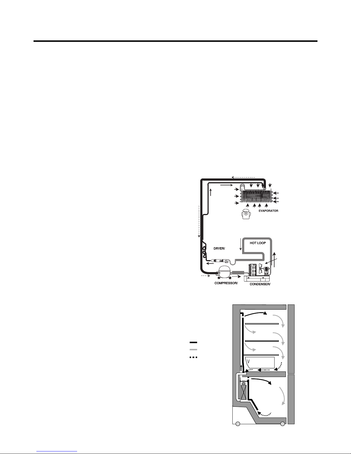
1-8 AIR FLOW / CIRCULATION D’AIR
1. SPECIFICATIONS
- 3 -
EVAPORATOR
COLD AIR
MIXED AIR
AIR RETURN TO
EVAPORATOR
FRESH FOOD
FREEZER
Ò
Vegetable box
EVAPORTOR FAN MOTOR
CONDENSER FAN MOTOR
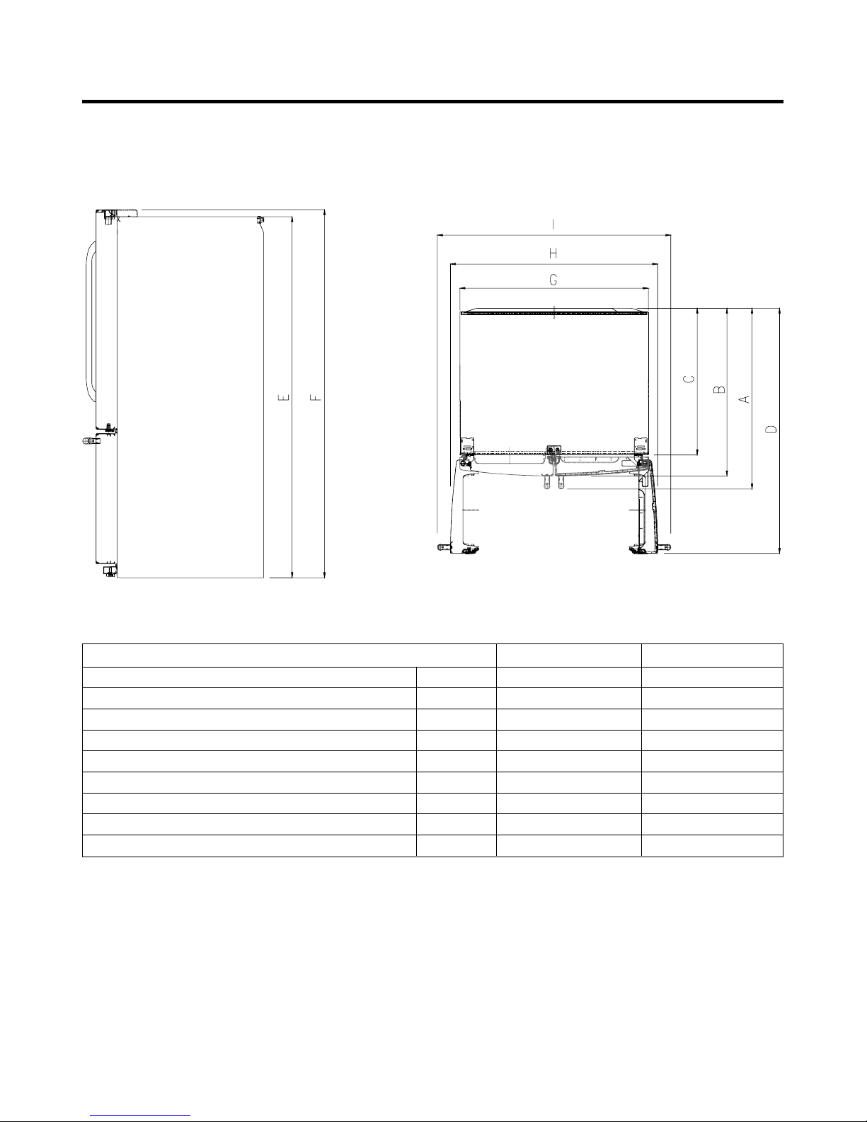
1-9 DIMENSIONS
- 4 -
Description 795.787** 795.785**
Depth w/ Handles A 30 in. 34 1/4 in.
Depth w/o Handles B 27 1/2 in. 31 3/4 in.
Depth w/o Door C 23 5/8 in. 27 7/8 in.
Depth (Total with Door Open) D 42 1/4 in. 46 1 /2 in.
Height to Top of Case E 68 3/8 in. 68 3/8 in.
Height to Top of Door Hinge F 69 3/4 in. 69 3/4 in.
Width G 35 3/4 in. 35 3/4 in.
Width (door open 90 deg. w/o handle) H 39 1/4 in. 39/1/4 in.
Width (door open 90 deg. w/ handle) I 44 1/4 in. 44 1/4 in.
- 5 -
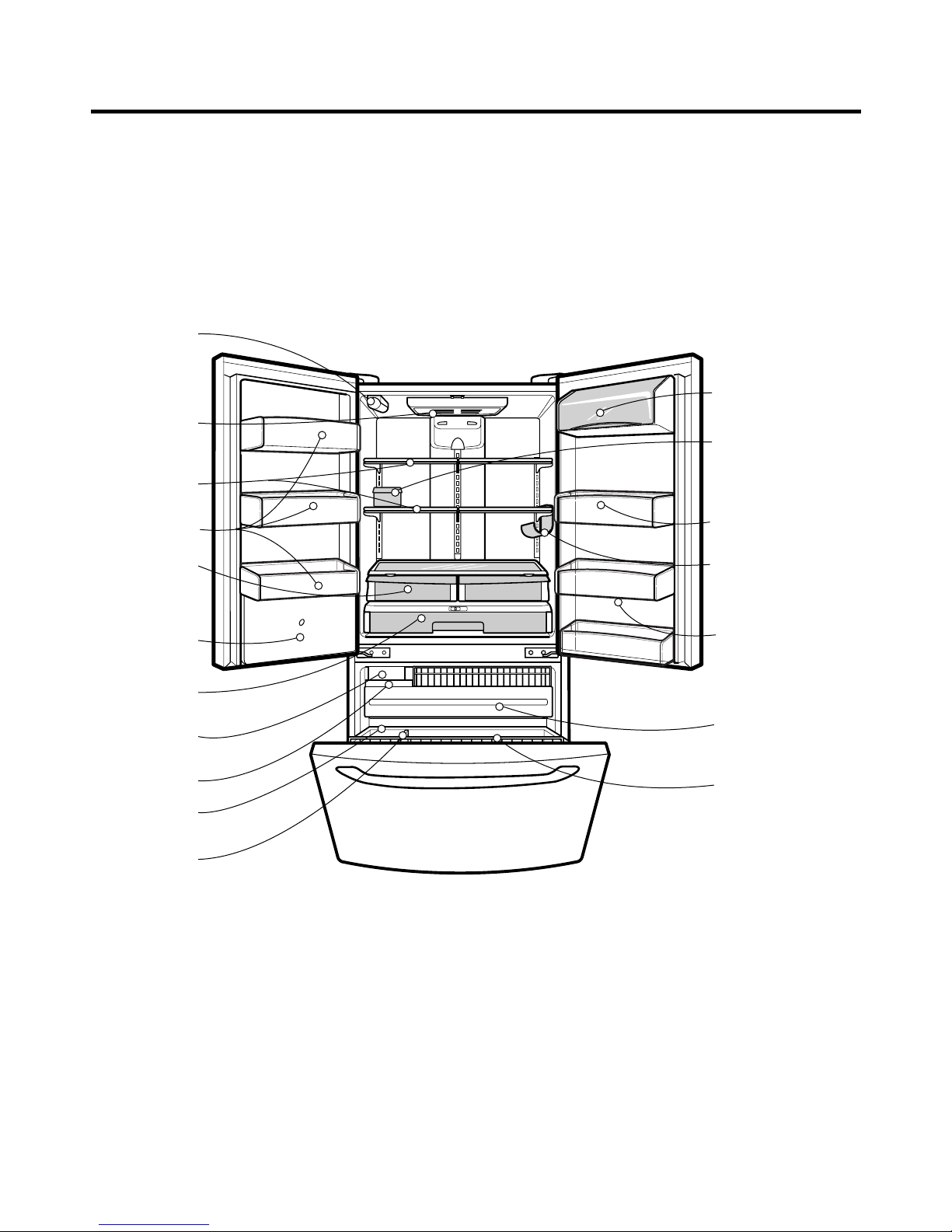
2. PARTS IDENTIFICATION
Refrigerator
Light
Refrigerator
Shelves
Humidity
Controlled
Crisper
Adjusta Cube
Ice Maker
Wide Pantry
Drawer
Ice Bin
Freezer
Drawer Bin
Divider
Pull out Drawer
Tilt-Out
Door Basket
Modular
Door Bins
Modular
Door Bins
Bottle Holder
(795.7855**
Models Only)
Dairy Bin
Utility/Egg Box
Door Bins
Water Filter
Water Tank
Cover
3-1 REMOVING AND REPLACING REFRIGERATOR DOORS
- 6 -
3. DISASSEMBLY
(1)
(2)
(4)
(5)
(6)
(3)
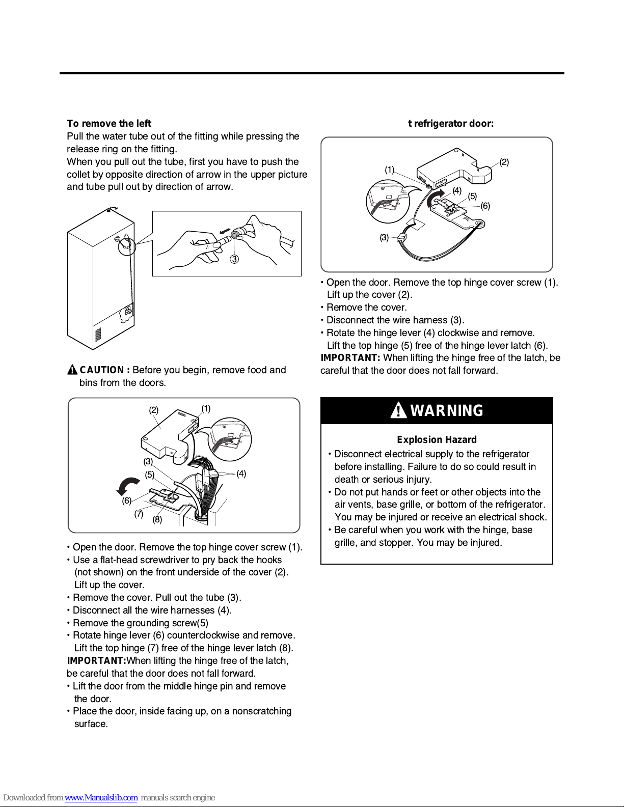
To remove the left refrigerator door:
Pull the water tube out of the fitting while pressing the
release ring on the fitting.
When you pull out the tube, first you have to push the
collet by opposite direction of arrow in the upper picture
and tube pull out by direction of arrow.
To remove the right refrigerator door:
¥ Open the door. Remove the top hinge cover screw (1).
Lift up the cover (2).
¥ Remove the cover.
¥ Disconnect the wire harness (3).
¥ Rotate the hinge lever (4) clockwise and remove.
Lift the top hinge (5) free of the hinge lever latch (6).
IMPORTANT:
When lifting the hinge free of the latch, be
careful that the door does not fall forward.
Explosion Hazard
WARNING
¥ Disconnect electrical supply to the refrigerator
before installing. Failure to do so could result in
death or serious injury.
¥ Do not put hands or feet or other objects into the
air vents, base grille, or bottom of the refrigerator.
You may be injured or receive an electrical shock.
¥ Be careful when you work with the hinge, base
grille, and stopper. You may be injured.
¥ Open the door. Remove the top hinge cover screw (1).
¥ Use a flat-head screwdriver to pry back the hooks
(not shown) on the front underside of the cover (2).
Lift up the cover.
¥ Remove the cover. Pull out the tube (3).
¥ Disconnect all the wire harnesses (4).
¥ Remove the grounding screw(5)
¥ Rotate hinge lever (6) counterclockwise and remove.
Lift the top hinge (7) free of the hinge lever latch (8).
IMPORTANT:
When lifting the hinge free of the latch,
be careful that the door does not fall forward.
¥ Lift the door from the middle hinge pin and remove
the door.
¥ Place the door, inside facing up, on a nonscratching
surface.
3
(1)
(2)
(4)
(3)
(6)
(7)
(8)
(5)
CAUTION :
Before you begin, remove food and
bins from the doors.
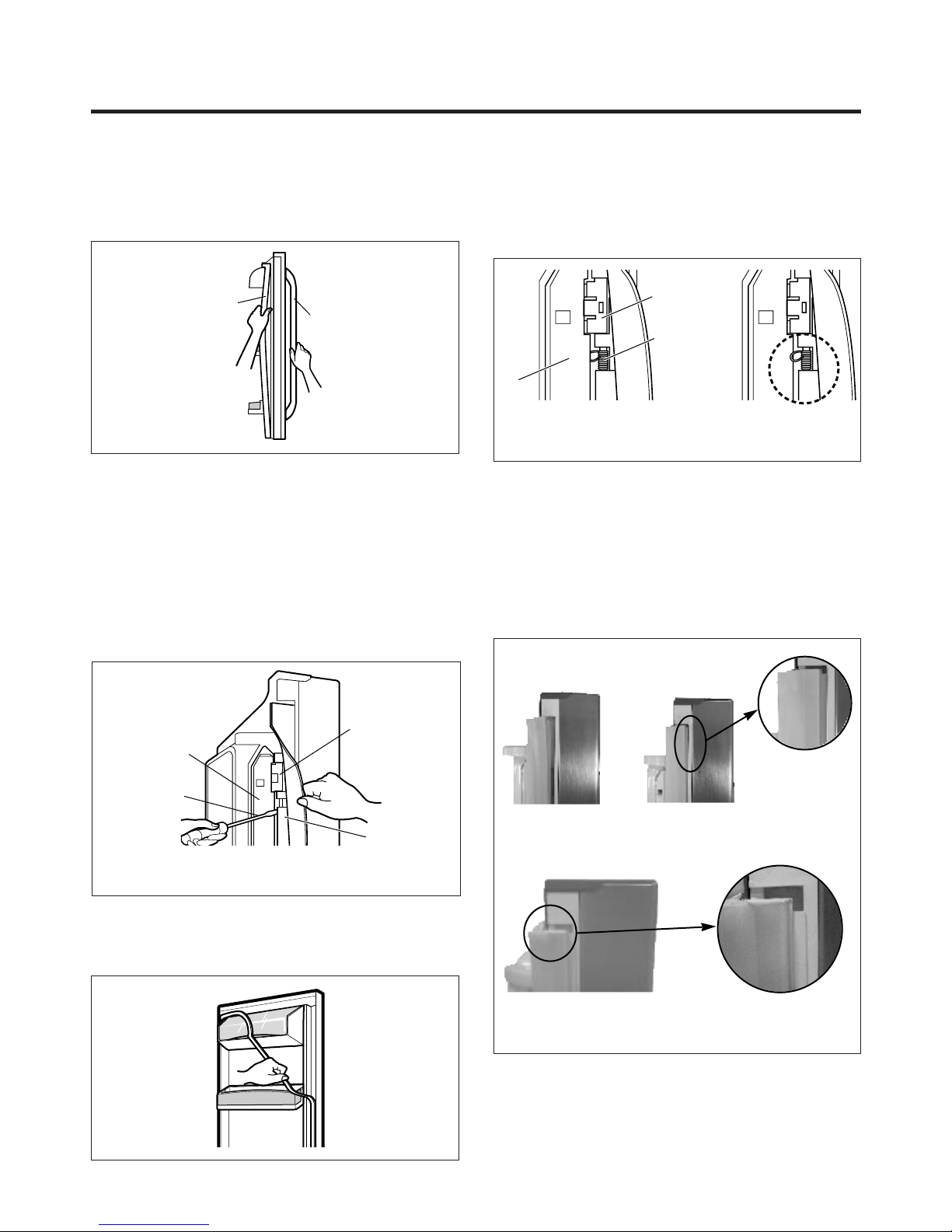
3-2 DOOR
● Door Gasket Removal
1. Remove door frame cover
Starting at top of cover and working down, snap cover
out and away from door.
2. Remove gasket bracket clips
There are two clips on each door. Start bracket removal
near one of the middle clips.
1) Pull gasket back to expose gasket bracket clip and
door frame.
2) Insert a flat tip screwdriver into seam between gasket
bracket and door frame and pry back until clips snaps
out.
3) Continue prying back along seam until all clips snap
out.
3. Remove gasket
Pull gasket free from gasket channel on the three
remaining sides of door.
● Door Gasket Replacement
1. Insert gasket bracket clips
1) Insert gasket bracket edge beneath door frame edge.
2) Turn upper gasket bracket spring so that the spring
ends are in the door channel.
3) Push in clip until you hear it snap securely into place.
4) Push in remaining two clips until you hear each snap
securely into place.
Note: Make sure that no part of gasket bracket edge
protrudes from beneath door frame edge.
2. Insert gasket into channel
1) Snap gasket assembly into the door bracket.
<Inserting the Gasket Assembly into the Bracket Door>
- 7 -
Frame Cover
Handle
Door
Frame
Gasket
Bracket Clip
Flat Tip
Screwdriver
Gasket
Bracket
Figure 1
Figure 2
Figure 3
Door
Frame
Gasket
Bracket Clip
Spring
IncorrectCorrect
Figure 4
Figure 5
Correct
Incorrect
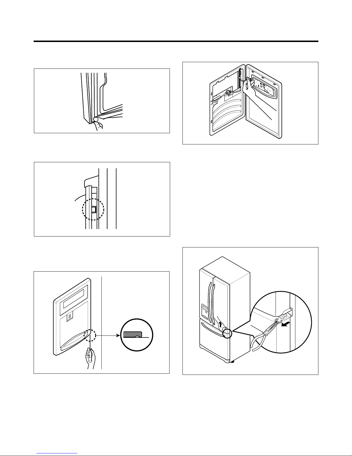
2) Press gasket into channels on the three remaining
sides of door.
3. Replace door frame cover
Starting at top of cover and working down, snap cover
back into door.
3-3 TO REMOVE THE DISPENSER
1. Use fiat tip screwdriver to pry back hooks on botton
underside of cover dispenser.
2. Pry off cover dispenser.
Disconnect wire harness.
3. Replace cover dispenser in opposite manner and order
of removal.
3-4 DOOR ALIGNMENT
If the space between your doors is uneven, follow the
instructions below to align the doors:
1. With one hand, lift up the door you want to raise at
middle hinge.
2. With other hand, use pliers to insert snap ring as shown.
3. Insert additional snap rings until the doors are aligned.
(Three snap rings are provided with unit.)
- 8 -
Figure 6
Figure 8
Figure 9
Figure 7
Figure 10
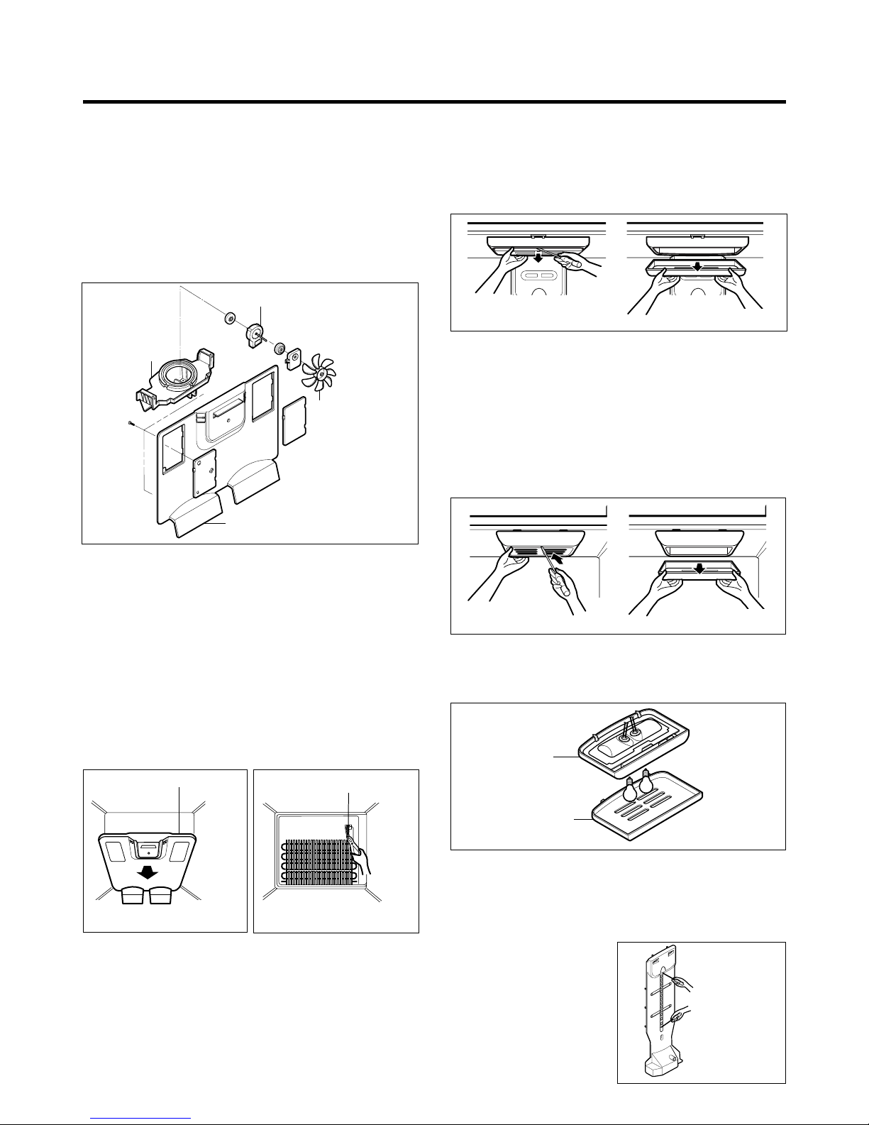
3-5 FAN AND FAN MOTOR
1. Remove the freezer shelf. (If your refrigerator has an
icemaker, remove the icemaker first)
2. Remove the plastic guide for slides on left side by
unscrewing phillips head screws.
3. Remove the grille by pulling it out and by loosening a screw.
4. Remove the Fan Motor assembly by loosening 2 screws
and disassemble the shroud.
5. Pull out the fan and separate the Fan Motor and Bracket.
3-6 DEFROST CONTROL ASSEMBLY
Defrost Control assembly consists of Defrost Sensor and
FUSE–M.
The Defrost Sensor works to defrost automatically . It is
attached to the metal side of the Evaporator and senses its
temperature. At 46°F(8°C), it turns the Defrost Heater off.
Fuse-M is a safety device for preventing over-heating of
the Heater when defrosting. At 172.8°F(77°C), it turns the
Defrost Heater off. It is attached to the between Eva pipe in
the middle Evaporator.
1. Pull out the grille assembly. (Figure 12)
2. Separate the connector with the Defrost Control
assembly and replace the Defrost Control assembly
after cutting the Tie Wrap. (Figure 13)
3-7 LAMP
3-7-1 Refrigerator Compartment Lamp
1. Unplug Refrigerator, or disconnect power at the circuit
breaker.
2. If necessary, remove top shelf or shelves.
3. Using a flat instrument, gently pry the cover loose in the
front as shown. Rotate downward to remove rear tabs.
4. Make sure the bulbs are cool to the touch.
Turn bulbs counterclockwise to remove.
5. Assemble in reverse order by snapping the Lamp Cover
in, engaging the rear tabs followed by the front tabs.
(Max. 60 W-2EA)
3-7-2 Freezer Compartment Lamp
1. Unplug refrigerator power cord form outlet.
2. Using a flat instrument, gently pry the lamp cover loose
in the front as shown. Rotate downward to remove the
rear tabs.
3. Make sure the bulb is cool to the touch. Turn the bulb
counterclockwise to remove.
4. Replace with a new 60-watt appliance bulb.
5. Insert tabs on back of cover into slots in freezer ceiling.
Push cover up to snap front into place.
3-8 CONTROL BOX-REFRIGERATOR
1. First, remove all shelves in the refrigerator, than remove
the Refrigerator control Box by loosening 2 screws.
2. Remove the Refrigerator Control Box by pulling it
downward.
3. Disconnect the lead wire on the right position and
separate the lamp sockets.
3-9 MULTI DUCT
1. Remove an upper and
lower Cap by using a flat
screwdriver, and loosen 2
screws. (Figure 17)
2. Disconnect the lead wire
on the bottom position.
- 9 -
BRACKET
MOTOR
GRILLE
FAN MOTOR
FAN
Figure 11
GRILLE ASSEMBLY
Figure 12
DEFROST-CONTROL
ASSEMBLY
Figure 13
Figure 14
Figure 15
CONTROL BOX
COVER LAMP
Figure 16
Figure 17
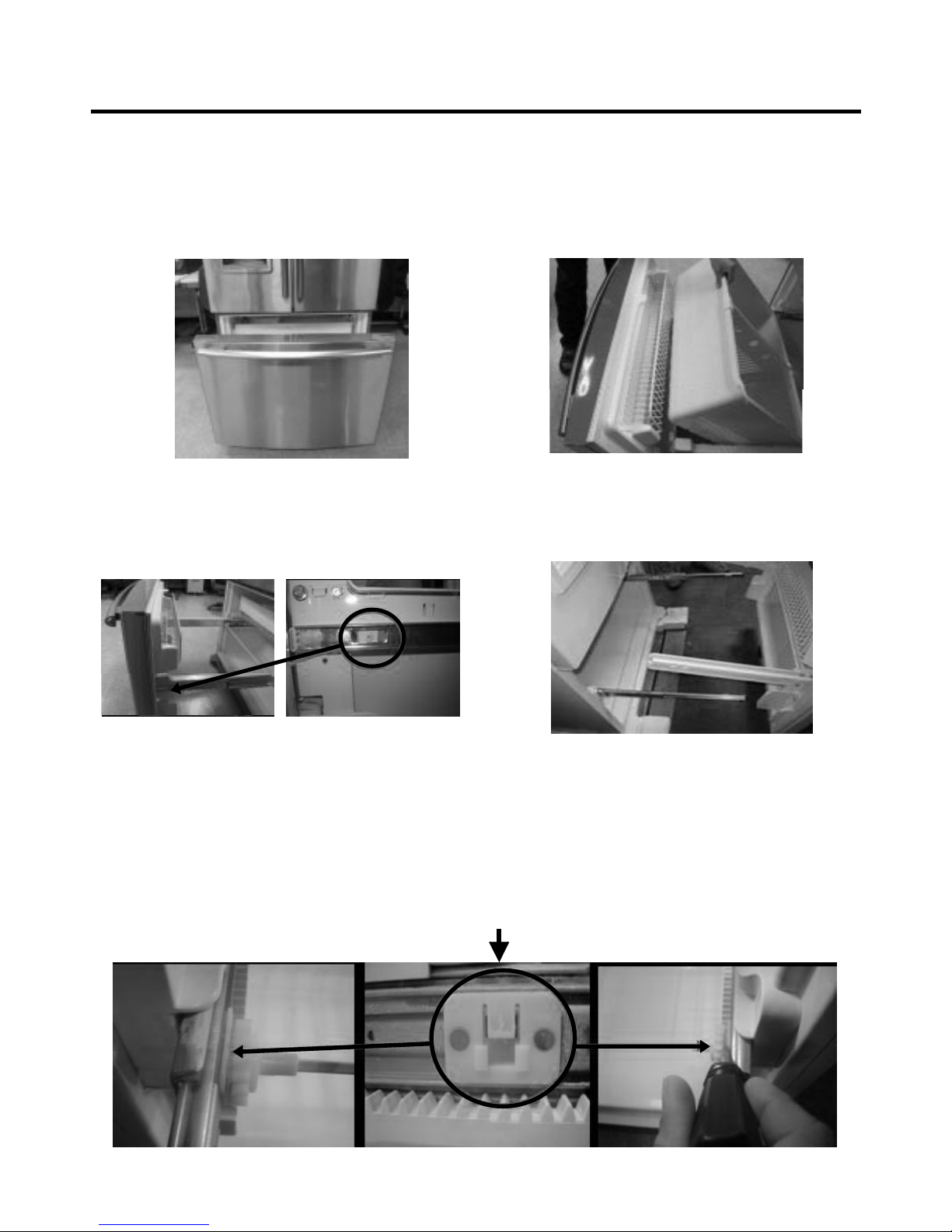
3-10 HOW TO REMOVE AND REINSTALL THE PULLOUT DRAWER
3-10-1 FOLLOW STEPS TO REMOVE
- 10 -
Step 1) Open the freezer door.
Step 3) Remove the two screws from the guide rails (one
from each side).
Step 2) Remove the lower basket.
Step 4) Lift the freezer door up to unhook it from the rail
support and remove.
Pull both rails to full extension.
Step 5) First: Remove the gear from the left side first by releasing the tab behind the gear, place a screwdriver between the
gear and the tab and pull up on the gear.
Second: Remove the center rail.
Third: Remove the gear from the right side by following the same steps for the left side.
NOTE: THIS TAB MUST BE PUSHED IN TO RELEASE THE GEAR.
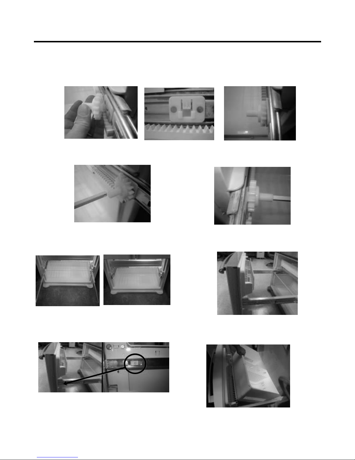
3-10-2 FOLLOW STEPS TO REINSTALL
Step 1) Reinstall the right side gear into the clip.
Step 2) Insert the rail into the right side gear. Gears do not
need to be perpendicular to each other.
Step 4) The rail system will align itself by pushing the rails
all the way into the freezer section.
Pull the rails back out to full extension.
Step 6) Reinstall the two screws into the guide rails
(one from each side).
Step 3) Insert the rail into the left side gear, and insert the
gear into the clip.
Step 5) Reinstall the freezer door by inserting the rail tabs
into the guide rail.
Step 7) Reinstall the lower basket, and close the freezer
door.
- 11 -
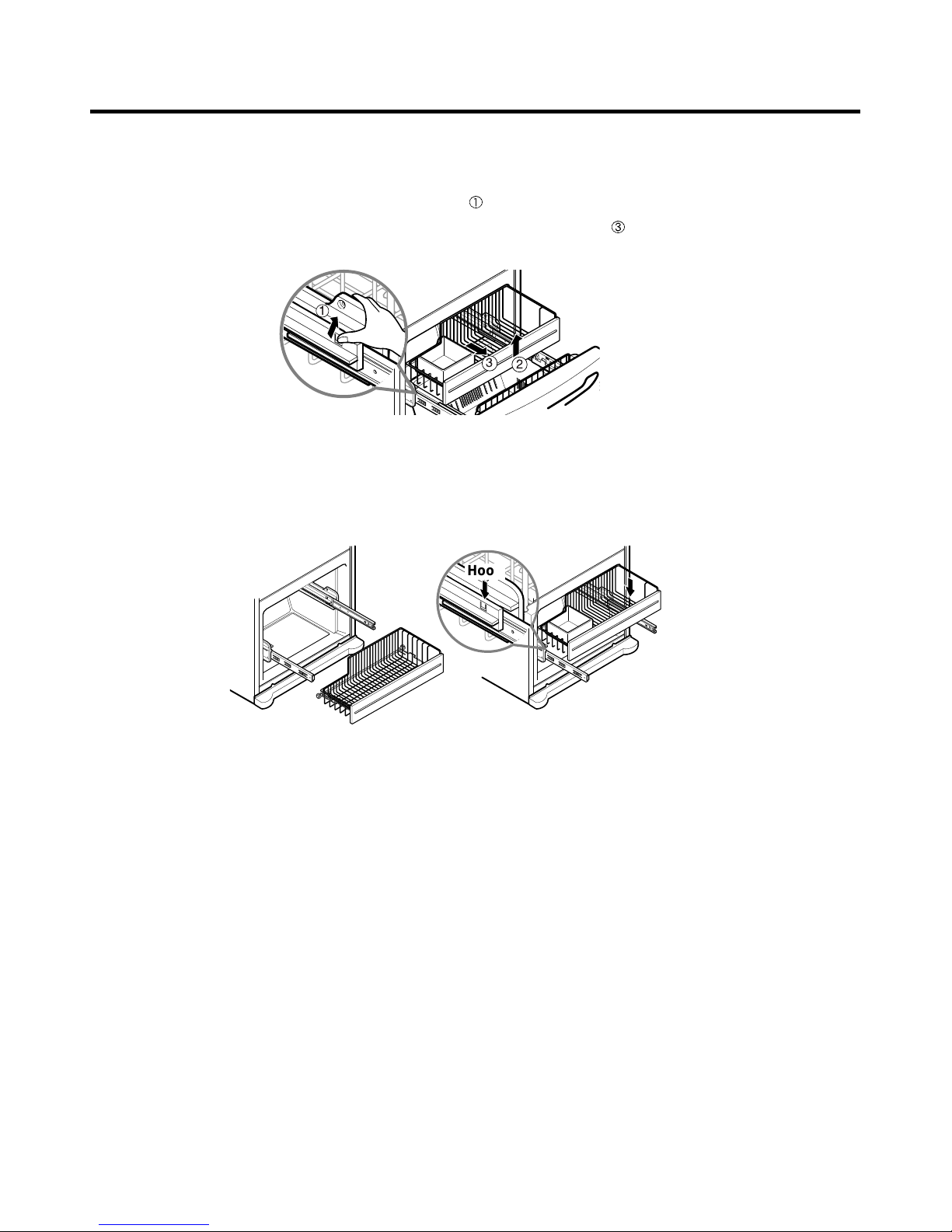
3-10-3 PULL OUT DRAWER
To separate the drawer, push the front left and right hooks in
direction to pull up and remove.
Then gently lift the gear part of rear left and right side of the drawer and pull it out in
direction.
To install, reposition the gear part of rear left and right side of the drawer after pulling out both rails as much as possible,
and gently push down both left and right side while checking the hook on the front part.
- 12 -
1
3
2
Hook
- 13 -
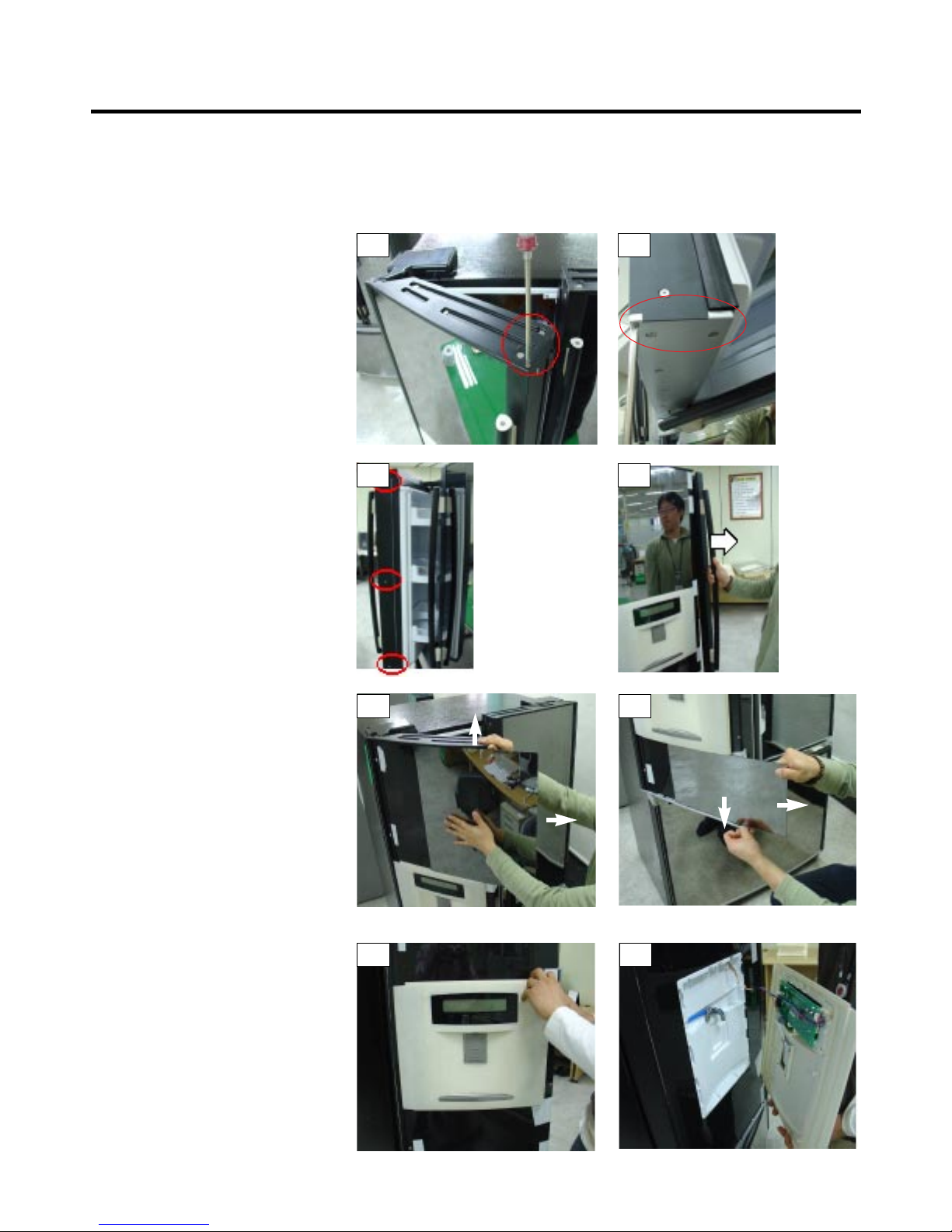
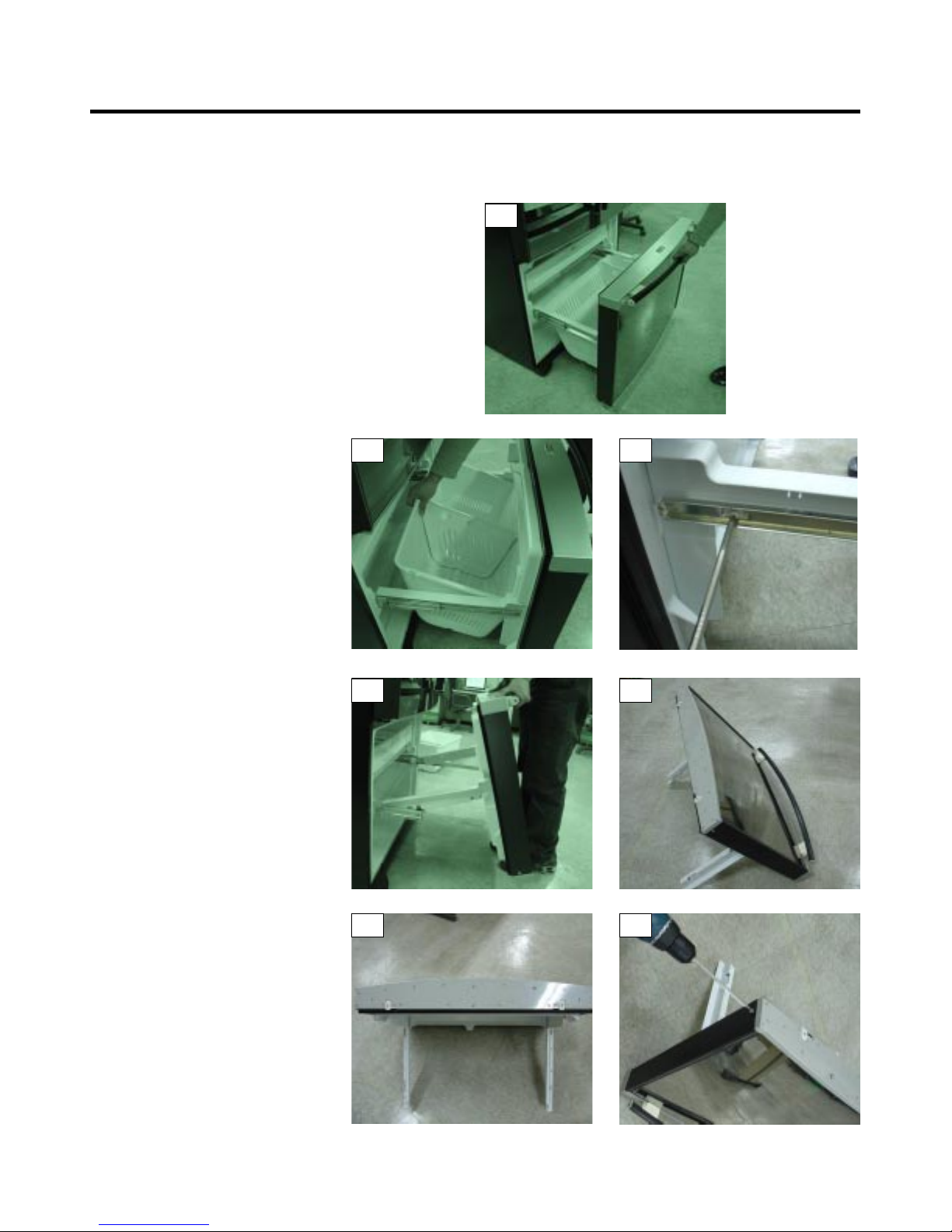
3-11 TRIM KIT ASSEMBLY AND AISASSEMBLY METHOD (795.77719,77729 MODELS ONLY)
3-11-1 ASSEMBLY AND DISASSEMBLY METHOD OF LEFT DOOR GLASS AND DISPLAY OF THE REFRIGERATOR
1. Remove the 2 screws on the top refrigerator door trim, circled in Photo
# 1.
2. Remove the 2 screws on the bottom
refrigerator door trim, circled in photo
# 2.
3. While holding the door handle (to
prevent it from falling) remove the 3
screws on the side trim that holds the
handle on.(see photo # 3)
4. Remove the door handle. (see photo
# 4)
5. While lifting up on the top door trim,
slide the glass front (above the
dispenser) to the right to remove it.
(see photo # 5)
6. While pulling down on the bottom door
trim, slide the glass front (below the
dispenser) to the right to remove it.
(see photo # 6)
7. Once the glass is removed, the
dispenser cover can be removed by
pulling it out by the right side and gently
pulling out of the left door trim slot. (see
photos 7 & 8)
8. The right side door glass is removed
in the same manner as the left.
However because it will not have the
dispenser the glass will be one
piece.
9. Reassemble in reverse order.
1
3
5
7 8
6
4
2
- 14 -
3-11-2 ASSEMBLY AND DISASSEMBLY METHOD OF FREEZER DOOR AND GLASS
1. Fully open the freezer drawer
as shown in photo # 1.
2. Lift out the freezer basket as
shown in photo # 2.
3. Remove the 2 screws
(one on each side shown in photo # 3.
4. Hold the freezer handle and pull
up to remove the door assembly,
as shown in photo # 4.
5. Put the freezer door facing down
(on a clean soft surface to prevent
scratching the top trim) as shown in photo # 5.
6. Remove all the screws hold the bottom
door trim in place. (be careful not to
remove the 2 screws circled in
photo # 6).
7. Remove the screw at the bottom of
each side trim shown in photo # 7.
(continued on the next page)
1
2 3
4 5
6 7
- 15 -
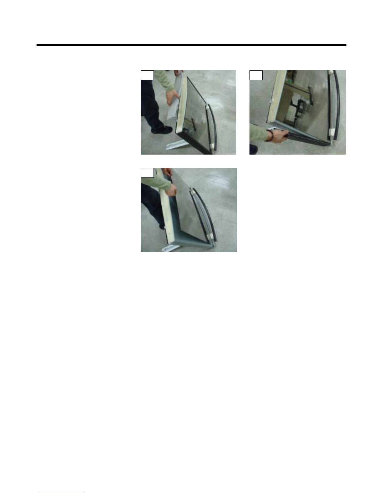
3-11-2 ASSEMBLY AND DISASSEMBLY METHOD OF FREEZER DOOR AND GLASS
8. Pull off the bottom cover as shown in
photo # 8.
9. Remove one of the side trim pieces by
pulling it out slightly the up to remove
it from the top door trim. As shown in
photo # 9.
10. Carefully pull out the freezer door
glass as shown in photo # 10.
11. Reassemble in reverse order.
8
10
9
4. ADJUSTMENT
- 16 -
4-1 COMPRESSOR
4-1-1 Role
The compressor intakes low temperature and low pressure
gas from the evaporator of the refrigerator and compresses
this gas to high-temperature and high-pressure gas. It then
delivers the gas to the condenser.
4-1-2 Composition
The compressor includes overload protection. The PTC
starter and OLP (overload protector) are attached to the
outside of the compressor. Since the compressor is
manufactured to tolerances of 1 micron and is hermetically
sealed in a dust and moisture-free environment, use
extreme caution when repairing it.
4-1-3 Note for usage
(1) Be careful not to allow over-voltage and over-current.
(2) If compressor is dropped or handled carelessly, poor
operation and noise may result.
(3) Use proper electric components appropriate to the
particular compressor in your product.
(4) Keep compressor dry.
If the compressor gets wet (in the rain or a damp
environment) and rust forms in the pin of the Hermetic
Terminal, poor operation and contact may result.
If the hermetic connector rusts out or fails, refrigerant
and oil will be expelled into the contact area, probably
resulting in smoke and fire.
(5) When replacing the compressor, be careful that dust,
humidity, and soldering flux don’t contaminate the inside
of the compressor. Contamination in the cylinder may
cause noise, improper operation or even cause it to
lock up.
4-2 TSD STARTER
4-2-3 TSD-Applied circuit diagram
● Starting method for the motor
4-2-4
ELECTRICAL AND DIMENSION DIAGRAM
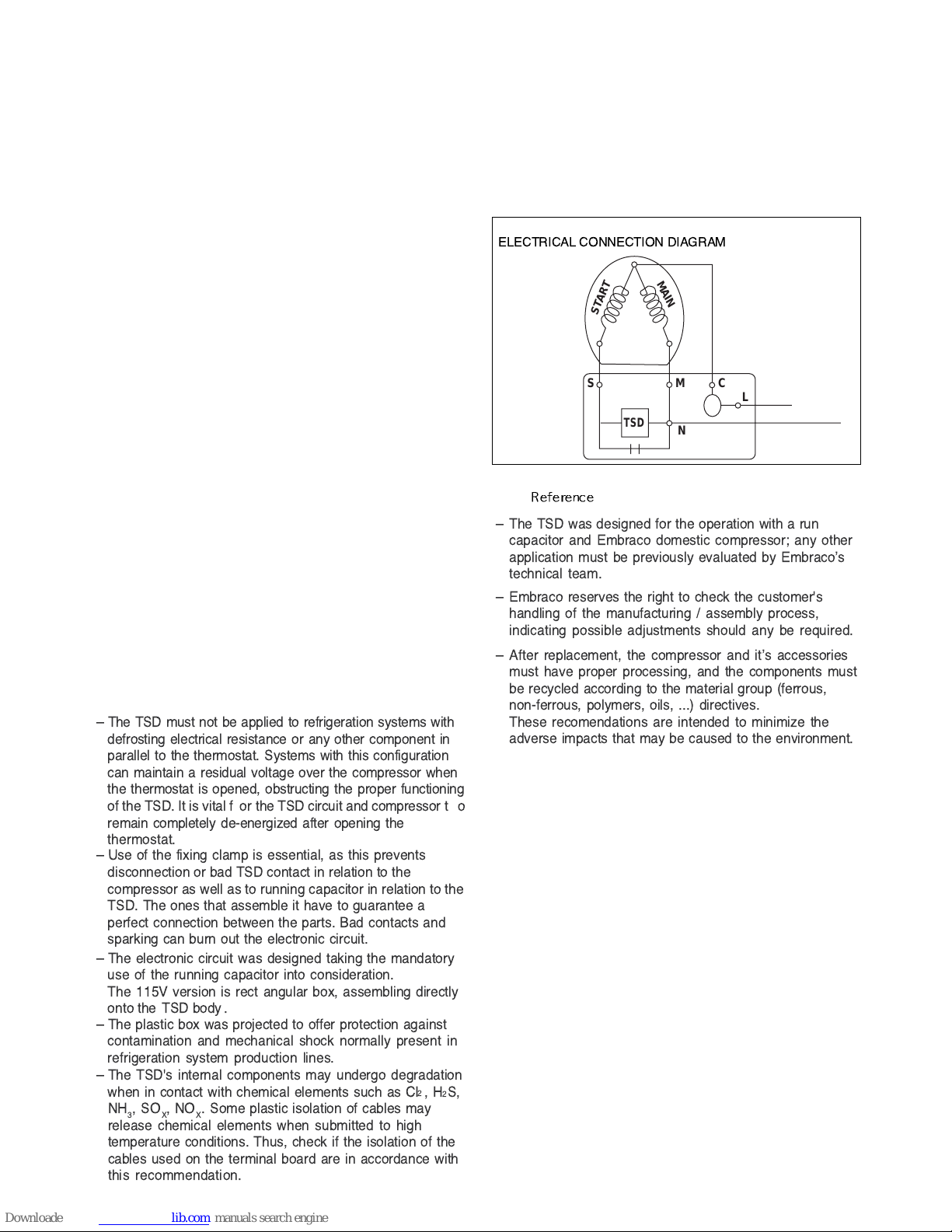
ELECTRICAL CONNECTION DIAGRAM
SM
TSD
START
MAIN
N
C
L
Ð The TSD must not be applied to refrigeration systems with
defrosting electrical resistance or any other component in
parallel to the thermostat. Systems with this configuration
can maintain a residual voltage over the compressor when
the thermostat is opened, obstructing the proper functioning
of the TSD. It is vital f or the TSD circuit and compressor t o
remain completely de-energized after opening the
thermostat.
Ð Use of the fixing clamp is essential, as this prevents
disconnection or bad TSD contact in relation to the
compressor as well as to running capacitor in relation to the
TSD. The ones that assemble it have to guarantee a
perfect connection between the parts. Bad contacts and
sparking can burn out the electronic circuit.
Ð The electronic circuit was designed taking the mandatory
use of the running capacitor into consideration.
The 115V version is rect angular box, assembling directly
onto the TSD body.
Ð The plastic box was projected to offer protection against
contamination and mechanical shock normally present in
refrigeration system production lines.
Ð The TSD's internal components may undergo degradation
when in contact with chemical elements such as CI
2
,H2S,
NH
3
,SOX,NOX. Some plastic isolation of cables may
release chemical elements when submitted to high
temperature conditions. Thus, check if the isolation of the
cables used on the terminal board are in accordance with
this recommendation.
Ð The TSD was designed for the operation with a run
capacitor and Embraco domestic compressor; any other
application must be previously evaluated by EmbracoÕs
technical team.
Ð Embraco reserves the right to check the customer's
handling of the manufacturing / assembly process,
indicating possible adjustments should any be required.
Ð After replacement, the compressor and itÕs accessories
must have proper processing, and the components must
be recycled according to the material group (ferrous,
non-ferrous, polymers, oils, ...) directives.
These recomendations are intended to minimize the
adverse impacts that may be caused to the environment.
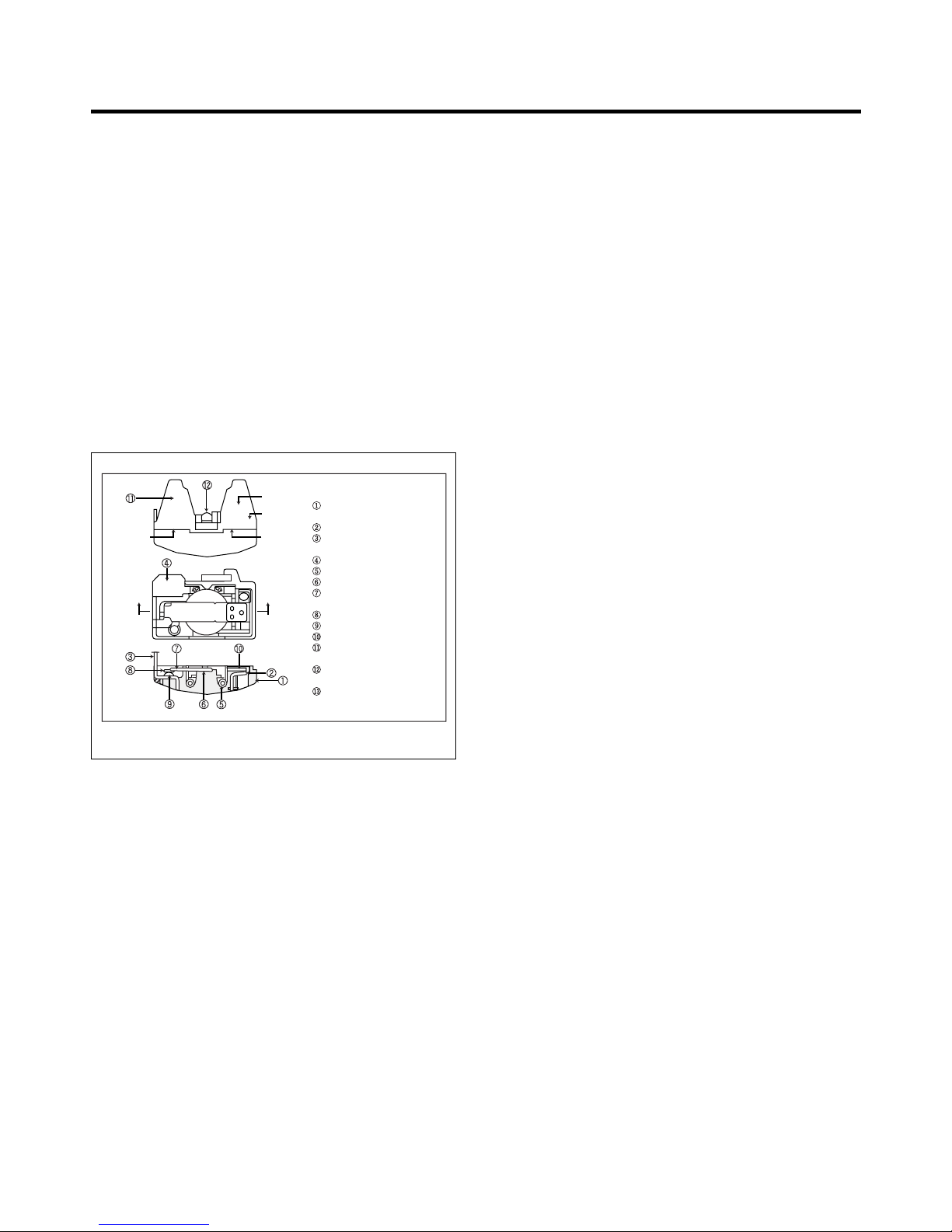
4-3 OLP (OVERLOAD PROTECTOR)
4-3-1 Definition of OLP
(1) OLP (OVERLOAD PROTECTOR) is attached to the
Compressor and protects the Motor by opening the
circuit to the Motor if the temperature rises and
activating the bimetal spring in the OLP.
(2) When high current flows to the Compressor motor, the
Bimetal works by heating the heater inside the OLP,
and the OLP protects the Motor by cutting off the
current flowing to the Compressor Motor.
4-3-2 Role of the OLP
(1) The OLP is attached to the Sealed Compressor used
for the Refrigerator. It prevents the Motor Coil from
being started in the Compressor.
(2) For normal operation of the OLP, do not turn the Adjust
Screw of the OLP in any way.
- 17 -
Part
Customer part
number
Lot code/
date code
330 FBYY -S1 BOX98
12345678
Physical
termination
part number
Electrical
characteristics
part number
No. Name
Base, phenolic
(UL 94 V-0 rated)
Movable arm support, plated steel
Stationary contact support,
plated steel
Heater support, plated steel
Heater, resistance alloy
Disc, thermostatic alloy
Movable arm, spring temper
copper alloy
Contact, movable, silver on copper
Contact, stationary, silver on copper
Slug, plated steel
Cover, polyester
(UL 94 V -0 rated)
Pin connector, plated copper alloy
(To engage 2.33/2.66 mm dia. pin)
Quick-connect terminal, brass,
conforms to UL 310, MEMA
DC-2, DIN 46344
(OVERLOAD PROTECTOR cross section)
Figure 19
 Loading...