

Kenmore 795.71089.01, 795.71083.01, 795.71082.01 Service Manual
REFRIGERATOR
SERVICE MANUAL
CAUTION
BEFORE SERVICING THE UNIT,
READ THE SAFETY PRECAUTIONS IN THIS MANUAL.
Model #s:
P/No. MFL48179017 (Last Revision: January. 18. 2010)
795.71082.01*
795.71083.01*
795.71089.01*

CONTENTS
SAFETY PRECAUTIONS ....................................................................................................................................................... 2
1. SPECIFICATIONS ........................................................................................................................................................... 3-4
2. PARTS IDENTIFICATION .................................................................................................................................................. 5
3. DISASSEMBLY ............................................................................................................................................................. 6-14
REMOVING AND REPLACING REFRIGERATOR DOORS .............................................................................................. 6
DOOR ................................................................................................................................................................................. 7
DOOR ALIGNMENT ........................................................................................................................................................... 8
FAN AND FAN MOTOR(Evaporator) .................................................................................................................................. 8
DEFROST CONTROL ASSEMBLY .................................................................................................................................... 9
LAMP .................................................................................................................................................................................. 9
MULTI DUCT .................................................................................................................................................................... 10
MAIN PWB ........................................................................................................................................................................ 10
DISPENSER ..................................................................................................................................................................... 10
DISPLAY PWB REPLACEMENT ...................................................................................................................................... 10
FUNNEL REPLACEMENT ................................................................................................................................................ 10
SUB PWB FOR DISPENSER ........................................................................................................................................... 11
DUCT DOOR REPLACEMENT ........................................................................................................................................ 11
ICE CORNER DOOR REPLACEMENT ............................................................................................................................ 11
ICEMAKER ASSEMBLY ................................................................................................................................................... 11
AUGER MOTOR COVER ................................................................................................................................................. 12
HOW TO REMOVE A DOOR ICE BIN .............................................................................................................................. 13
HOW TO INSERT A DOOR ICE BIN ................................................................................................................................ 13
HOW TO REMOVE AND REINSTALL THE PULLOUT DRAWER .............................................................................. 14-15
WATER VALVE DISASSEMBLY METHOD ...................................................................................................................... 16
FAN AND FAN MOTOR DISASSEMBLY METHOD ......................................................................................................... 16
PULL OUT DRAWER ........................................................................................................................................................ 17
4. ADJUSTMENT ............................................................................................................................................................ 18-19
COMPRESSOR ................................................................................................................................................................ 18
PTC-STARTER ................................................................................................................................................................. 18
OLP(OVERLOAD PROTECTOR) ..................................................................................................................................... 19
TO REMOVE THE COVER PTC ...................................................................................................................................... 19
5. CIRCUIT DIAGRAM ......................................................................................................................................................... 20
6. TROUBLESHOOTING ................................................................................................................................................ 21-25
7. OPERATION PRINCIPLE AND REPAIR METHOD OF ICEMAKER ......................................................................... 26-28
8. DESCRIPTION OF FUNCTION & CIRCUIT OF MICOM ............................................................................................ 29-45
SAFETY PRECAUTIONS
Please read the following instructions before servicing your
refrigerator.
1. Unplug the power before handling any elctrical componets.
2. Check the rated current, voltage, and capacity.
3. Take caution not to get water near any electrical
components.
4. Use exact replacement parts.
5. Remove any objects from the top prior to tilting the
product.
- 2 -
1. SPECIFICATIONS
1-1 DISCONNECT POWER CORD BEFORE
SERVICING
IMPORTANT - RECONNECT ALL
GROUNDING DEVICES
All parts of this appliance capable of conducting electrical
current are grounded. If grounding wires, screws, straps,
clips, nuts or washers used to complete a path to ground
are removed for service, they must be returned to their
original position and properly fastened.
1-2 IMPORTANT NOTICE
This information is intended for use by individuals
possessing adequate backgrounds of electrical, electronic
and mechanical experience. Any attempt to repair a major
appliance may result in personal injury and property
damage. The manufacturer or seller cannot be responsible
for the interpretation of this information, nor can it assume
any liability in connection with its use.
1-3 ELECTRICAL SPECIFICATIONS
Temperature Control (Freezer Compartment) .. -6°F to +8°F
Defrost Control .....Total Comp Running Time: 7 hrs~50 hrs
Defrost Thermostat ...................................................... 46°F
Electrical Rating : 115VAC, 60Hz ................................ 7.2 A
Maximum Current Leakage ...................................... 0.5 mA
Maximum Ground Path Resistance ................... 0.14 Ohms
Energy Consumption ....................... 21 cu.ft. 527 (E/STAR)
.......................................................... 25 cu.ft. 547 (E/STAR)
1-7 REPLACEMENT PARTS
21 cuft
795.71082.01*
795.71083.01*
795.71089.01*
Relay ............................................................ EBG60658602
Overload ........................................................ 6750C-0004U
Defrost Thermostat ....................................... 6615JB2005H
Defrost Heater ............................................... 5300JK1005D
Evaporator Fan Motor ................................... 4681JB1027C
(4681JK1004E)
Capacitor (Running) ..................................... 0CZZJB2014K
(0CZZJB2012K)
Compressor (Hi-Side) ................................... TCA34632301
Evaporator (Lo-Side) ..................................... 5421JJ1003B
Condenser ................................................... ACG72915201
Dryer ............................................................. 5851JA2007E
Condenser Fan Motor ................................... 4681JB1029D
Temperature Control ............................ ACQ36820506(SW)
ACQ36820507(WB)
ACQ36820508(BI)
ACQ36820509(STS)
ACQ36820510(BS)
Main Control ................................................. EBR41956436
Ice Fan Motor ................................................ 4681JB1027E
1-4 NO LOAD PERFORMANCE
CONTROL POSITION : MID/MID
And Ambient of : ................ 70°F ................................. 90°F
Fresh Food, °F .................. 33°F to 41°F ........ 33°F to 41°F
Frozen Food, °F ................ -4°F to +4°F ......... -4°F to +4°F
Percent Running Time ...... 35%-45% ................. 50°F-70°F
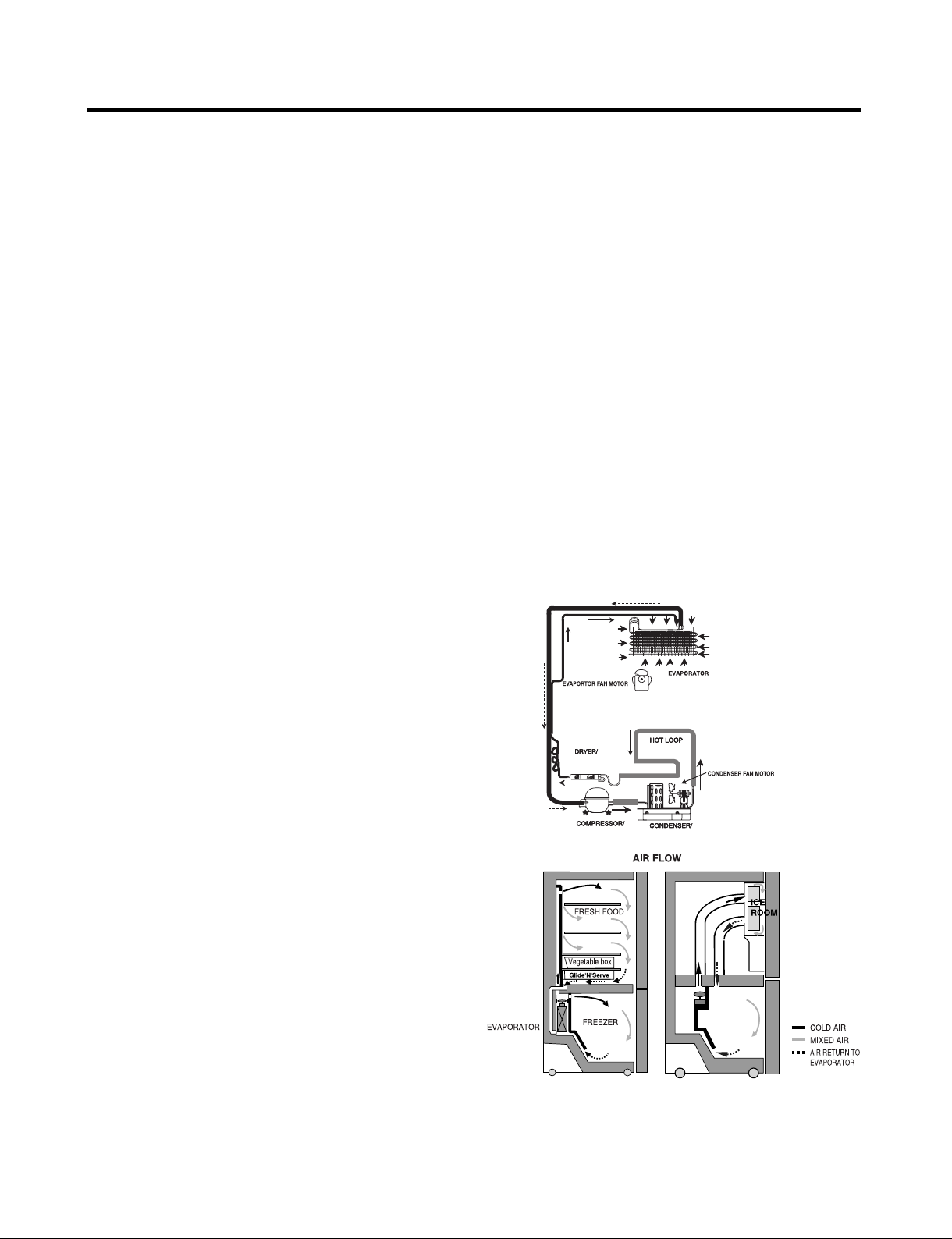
1-5 REFRIGERATION SYSTEM
Minimum Compressor Capacity Vacuum ................ 21 MIN.
Minimum Equalized Pressure
@ 70°F ............................................................ 49 PSIG
@ 90°F ............................................................ 56 PSIG
Refrigerant R134a ................................................... 5.11 oz.
Compressor ....................................................... 956 BTU/hr
1-6 INSTALLATION
Clearance must be provided at top, sides and rear of the
refrigerator for air circulation.
AT REAR ....................................................................... 1 in
1-8 AIR FLOW / CIRCULATION D’AIR
- 3 -
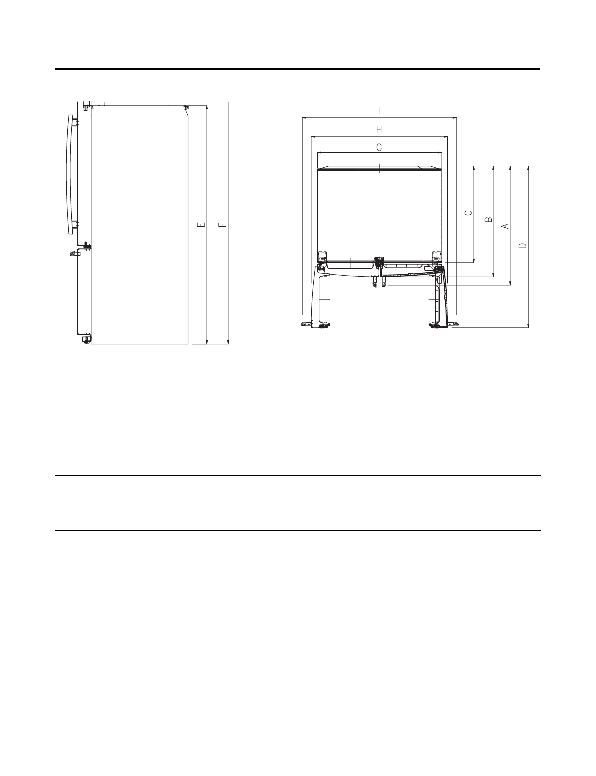
Depth w/ Handles
Description 795.71082.01*
A
30 in.
Depth w/ o Handles
Depth w/ o Door
Depth (Total with Door Open)
Height to Top of Case
Height to Top of Door Hinge
Width
Width (door open 90 deg. w/o handle)
Width (door open 90 deg. w/ handle)
B
C
D
E
F
G
H
I
27 1/2 in.
23 5/8 in.
42 1/4 in.
68 3/8 in.
69 3/4 in.
35 3/4 in.
39 1/4 in.
44 1/4 in.
- 4 -
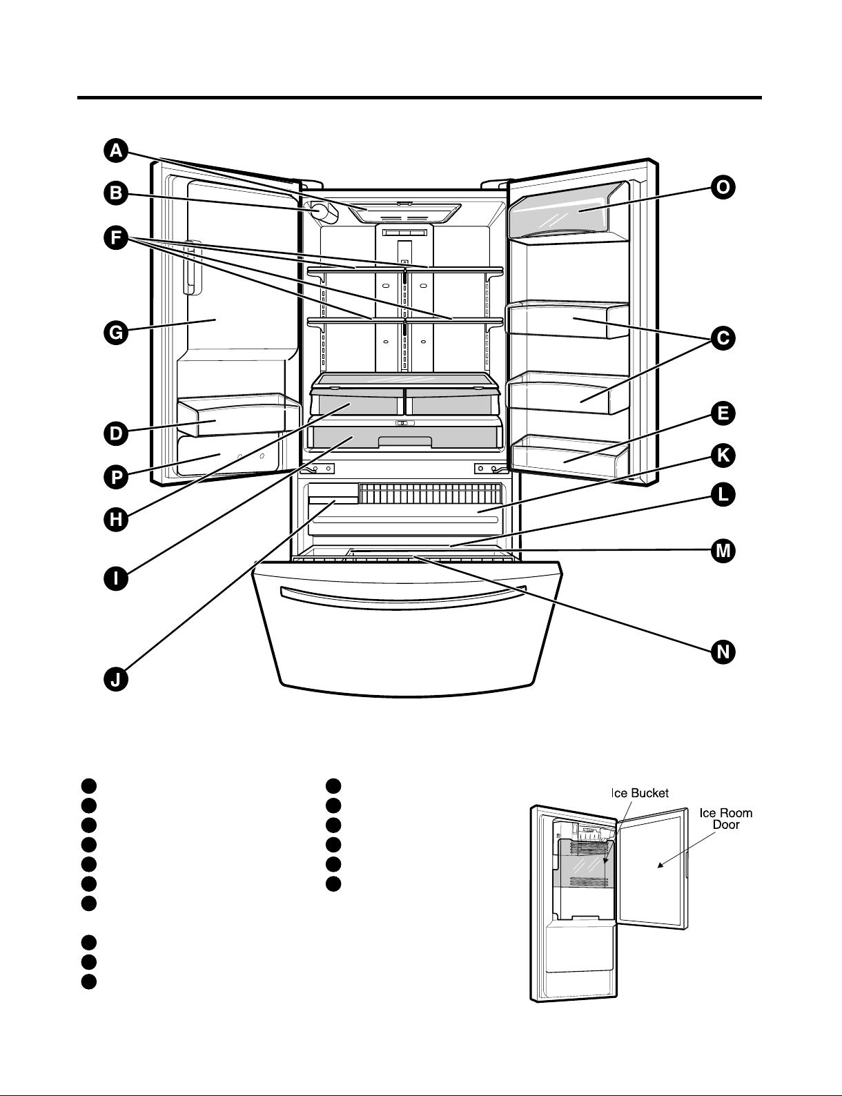
2. PARTS IDENTIFICATION
Use this page to become more familiar with the parts and features. Page references are included for your convenience.
NOTE : This guide covers several different models. The refrigerator you have purchased may have some or all of the items
listed below. The locations of the features shown below may not match your model.
Refrigerator Light
A
Filter (Inside)
B
Modular Door Bins
C
Fixed door bin
D
E
Fixed door bin
F
Refrigerator Shelves
G
Ice Room
Pull out Drawer
K
Durabase
L
Divider
M
Tilt-Out Door Basket
N
O
Dairy Bin
P
Water Tank Cover
(Ice Maker and Ice Bucket)
H
Humidity Controlled Crisper
I
Glide‘N’Serve
J
Extra Ice Bin
- 5 -
3. DISASSEMBLY
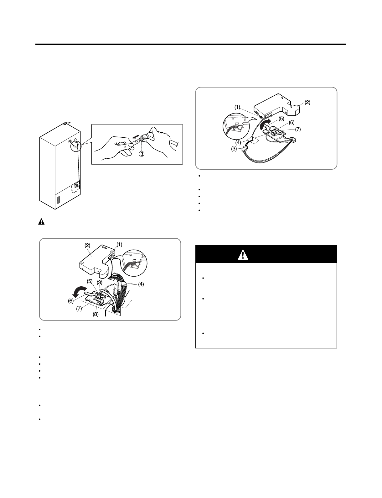
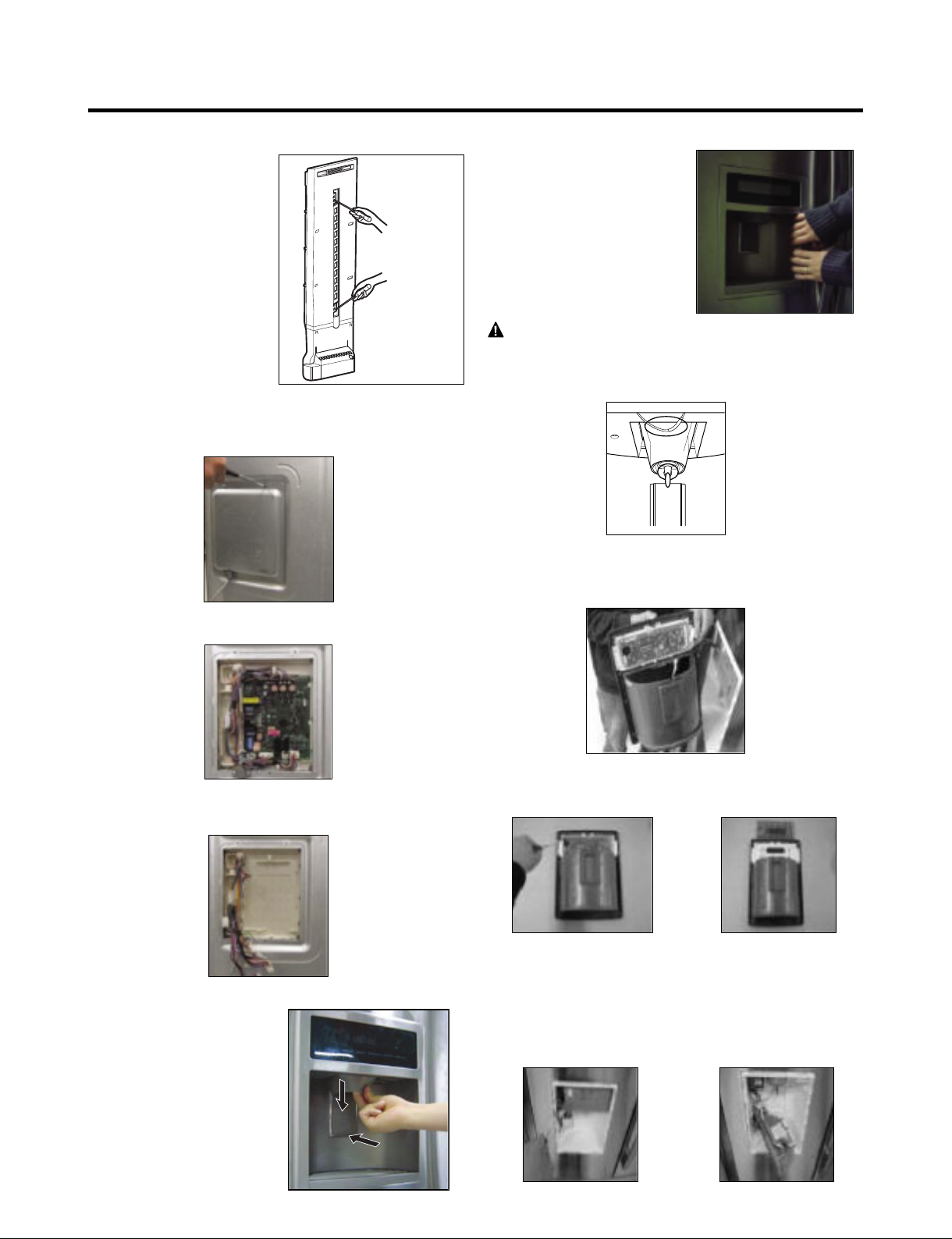
3-1 REMOVING AND REPLACING REFRIGERATOR DOORS
To remove the left refrigerator door:
Pull the water tube out of the fitting while pressing the
release ring on the fitting.
When you pull out the tube, first you have to push the collet
by opposite direction of arrow in the upper picture and tube
pull out by direction of arrow.
CAUTION : Before you begin, remove food and
bins from the doors.
To remove the right refrigerator door:
Open the door. Remove the top hinge cover screw (1).
Lift up the cover (2).
Remove the cover.
Disconnect the wire harness (3).
Remove the grounding screw (4).
Rotate the hinge lever (5) clockwise and remove.
Lift the top hinge (6) free of the hinge lever latch (7).
IMPORTANT : When lifting the hinge free of the latch, be
careful that the door does not fall forward.
WARNING
Open the door. Remove the top hinge cover screw (1).
Use a flat-head screwdriver to pry back the hooks
(not shown) on the front underside of the cover (2).
Lift up the cover.
Remove the cover. Pull out the tube (3).
Disconnect all the wire harnesses (4).
Remove the grounding screw(5)
Rotate hinge lever (6) counterclockwise and remove.
Lift the top hinge (7) free of the hinge lever latch (8).
IMPORTANT : When lifting the hinge free of the latch, be
careful that the door does not fall forward.
Lift the door from the middle hinge pin and remove the
door.
Place the door, inside facing up, on a nonscratching
surface.
Explosion Hazard
Disconnect electrical supply to the refrigerator
before installing. Failure to do so could result in
death or serious injury.
Do not put hands or feet or other objects into
the air vents, base grille, or bottom of the
refrigerator.
You may be injured or receive an electrical
shock.
Be careful when you work with the hinge, base
grille, and stopper. You may be injured.
- 6 -
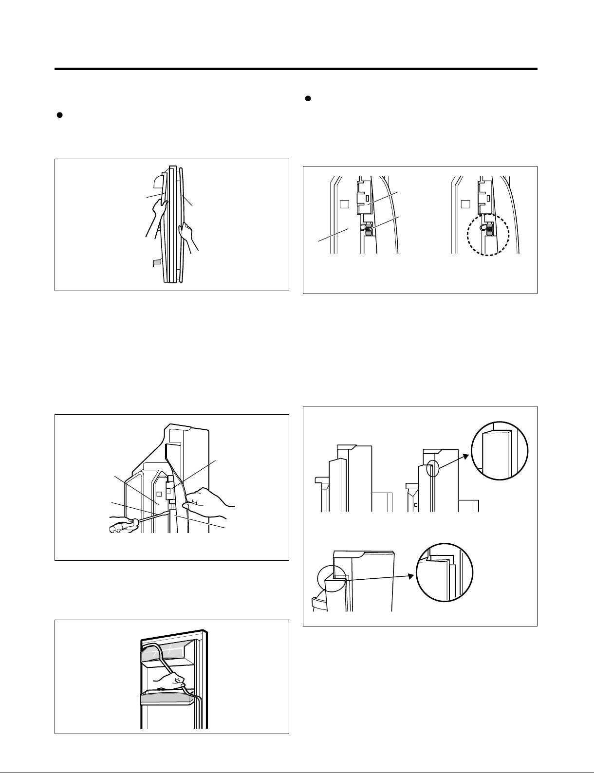
3-2 DOOR
Door Gasket Removal
1. Remove door frame cover
Starting at top of cover and working down, snap cover
out and away from door.
Door Gasket Replacement
1. Insert gasket bracket clips
1) Insert gasket bracket edge beneath door frame edge.
2) Turn upper gasket bracket spring so that the spring
ends are in the door channel.
3) Push in clip until you hear it snap securely into place.
Frame Cover
Handle
Figure 1
2. Remove gasket bracket clips
There are two clips on each door. Start bracket removal
near one of the middle clips.
1)Pull gasket back to expose gasket bracket clip and
door frame.
2)Insert a flat tip screwdriver into seam between gasket
bracket and door frame and pry back until clips snap
out.
3)Continue prying back along seam until all clips snap
out.
Gasket
Door
Frame
Bracket Clip
Gasket
Bracket Clip
Spring
Door
Frame
4) Push in remaining clip until you hear it snap securely
Note : Make sure that no part of gasket bracket edge
2. Insert gasket into channel
1) Snap gasket assembly into the door bracket.
<Inserting the Gasket Assembly into the Bracket Door>
Correct
into place.
protrudes from beneath door frame edge.
Incorrect
Figure 4
Flat Tip
Screwdriver
3. Remove gasket
Pull gasket free from gasket channel on the three
remaining sides of door.
Gasket
Bracket
Figure 2
Figure 3
- 7 -
Incorrect
Correct
Figure 5
2) Press gasket into channels on the three remaining
sides of door.
Figure 6
3. Replace door frame cover
Starting at top of cover and working down, snap cover
back into door.
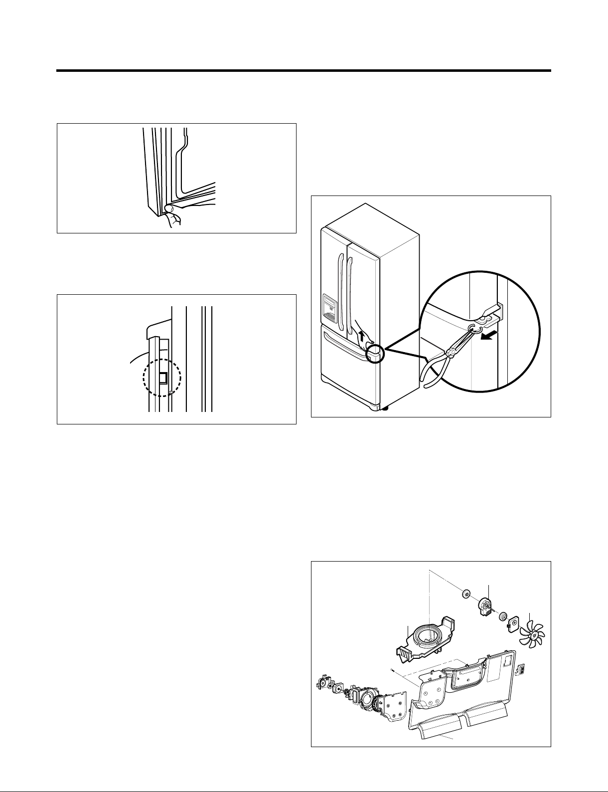
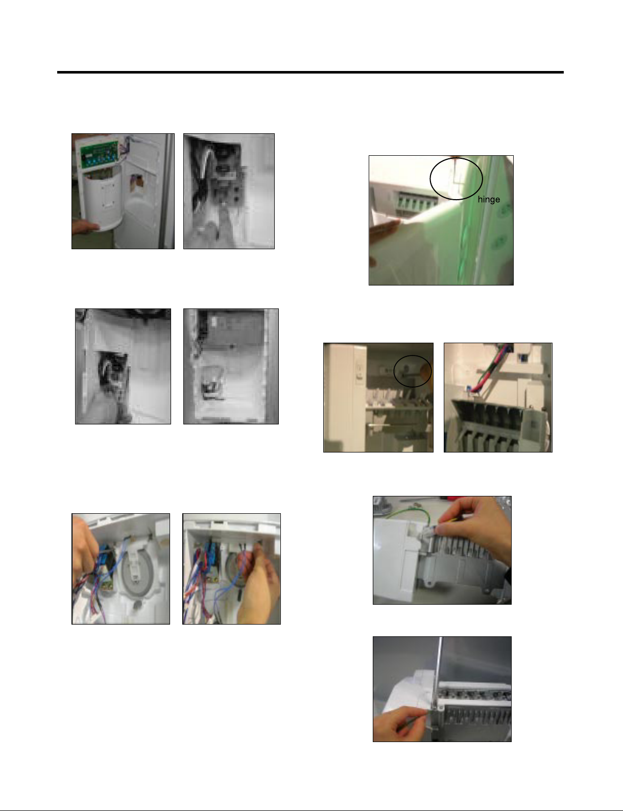
3-3 DOOR ALIGNMENT
If the space between your doors is uneven, follow the
instructions below to align the doors :
1. With one hand, lift up the door you want to raise at
middle hinge.
2. With other hand, use pliers to insert snap ring as shown.
3. Insert additional snap rings until the doors are aligned.
(Three snap rings are provided with unit.)
Figure 7
Figure 10
3-4 FAN AND FAN MOTOR(EVAPORATOR)
1. Remove the freezer shelf. (If your refrigerator has an
icemaker, remove the icemaker first)
2. Remove the plastic guide for slides on left side by
unscrewing phillips head screws.
3. Remove the grille by removing one screw and pulling the
grille forward.
4. Remove the Fan Motor assembly by loosening 2 screws
and disassembling the shroud.
5. Pull out the fan and separate the Fan Motor and Bracket.
FAN MOTOR
BRACKET
MOTOR
FAN
- 8 -
GRILLE
Figure 11
* Ice Fan Scroll Assembly Replacement
1) Remove the plastic guide for slides on left side by
unscrewing phillips head screws.
2) Pull the grille forward as shown in the second picture.
3) Disconnect wire harness of the grille.
4) Remove the scroll assembly by loosening all screws.
(1) (2)
(3) (4)
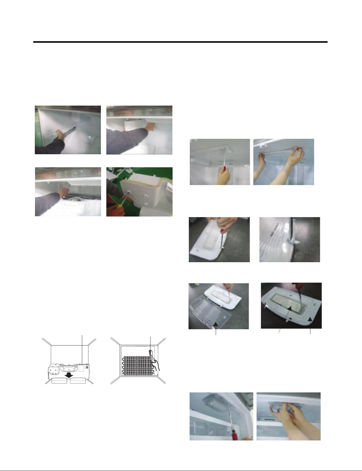
3-6 LAMP
Unplug Refrigerator, or disconnect power at the circuit
breaker.
If necessary, remove top shelf or shelves.
3-6-1 Refrigerator Compartment Lamp
1) Release 2 screws.
2) Hold both ends with your both hands and pull it
downward to remove it.
3) Use a flat tool as shown below to remove the cover
lamp.
Figure 12
4) As shown below, use a flat tool to remove the cover
lamp.
3-5 DEFROST CONTROL ASSEMBLY
Defrost Control assembly consists of Defrost Sensor and
FUSE-M.
The Defrost Sensor works to defrost automatically. It is
attached to the metal side of the Evaporator and senses its
temperature. At 46°F (8°C), it turns the Defrost Heater off.
Fuse-M is a safety device for preventing over-heating of the
Heater when defrosting.
1. Pull out the grille assembly. (Figure 10)
2. Separate the connector with the Defrost Control
assembly and replace the Defrost Control assembly after
cutting the Tie Wrap. (Figure 11)
GRILLE ASSEMBLY
Figure 10 Figure 11
DEFROST-CONTROL
ASSEMBLY
Figure 13
Cover, Lamp
3-6-2 Freezer Compartment Lamp
1. Unplug refrigerator power cord form outlet.
2. Remove screw with direver.
3. Grasp the cover Lamp, pull the cover downward.
LED, Assembly Case Lamp
Figure 14
- 9 -
Figure 15
3-7 MULTI DUCT
1. Remove the upper and
lower Caps by using a
flat screwdriver, and
remove 2 screws.
(Figure 17)
2. Disconnect the lead wire
on the bottom position.
3-8 MAIN PWB
1) Loosen the 4 screws on the PWB cover.
Figure 17
2) Hold the left and right side
of the “Cover Assembly,
dispenser” as shown in the
picture, and pull and
remove it. The cover
dispenser is attached with a
hook.
CAUTION : When replacing the dispenser cover in the
reverse order of removal, be careful that the lead wire
does not come out and the water tube is not pinched by
the dispenser cover, as shown in the picture below.
3-10 DISPLAY PWB REPLACEMENT
1) Pull up and out on the dispenser cover to remove.
2) Remove the PWB cover
3) Disconnect wire harness and replace the main PWB in
the reverse order of removal.
3-9 DISPENSER
1) Disconnect funnel and
button assembly by
pulling down and
forward.
2) Follow the steps in the pictures
3-11 FUNNEL REPLACEMENT
1) Pull up and out on the dispenser cover to remove.
2) Disconnect the wire harness.
3) Replace in reverse order.
- 10 -
3-12 SUB PWB FOR WORKING DISPENSER 3-14 ICE CORNER DOOR REPLACEMENT
1) Loosen the screw on the sub PWB. 1) Loosen the front screw as shown in the picture.
2) Lift up the hinge with one hand.
3) Pull out the Ice Corner Door with the other hand.
2) Pull the sub PWB down.
3) Disconnect the wire harness and replace the sub PWB in
the reverse order of removal.
3-15 ICEMAKER ASSEMBLY
1) Loosen two screws as shown in the first picture.
3-13 DUCT DOOR REPLACEMENT
1) Pull up and out on the dispenser cover to remove.
2) Disconnect the wire harness.
3) Remove the funnel
4) Replace in reverse order.
2) Disconnect the wire harness & ground screw replace
theIcemaker assembly in the reverse order of removal.
3) It separates a ground connection screw.
- 11 -
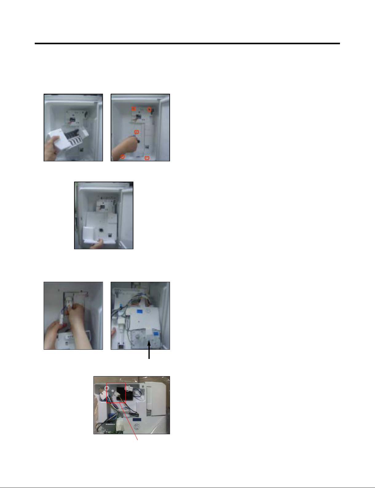
3-16 AUGER MOTOR COVER
1) After removing the icemaker remove the (5) stainless
screws holding the auger motor cover, shown in the
picutres below.
2) Grip the bottom of motor cover assembly and pull out it.
3) Disconnect wire harness of motor cover assembly.
There is a auger motor on the back, as shown in the
picture.
Auger Motor
Icemaker Power &
Full detection Signal
- 12 -
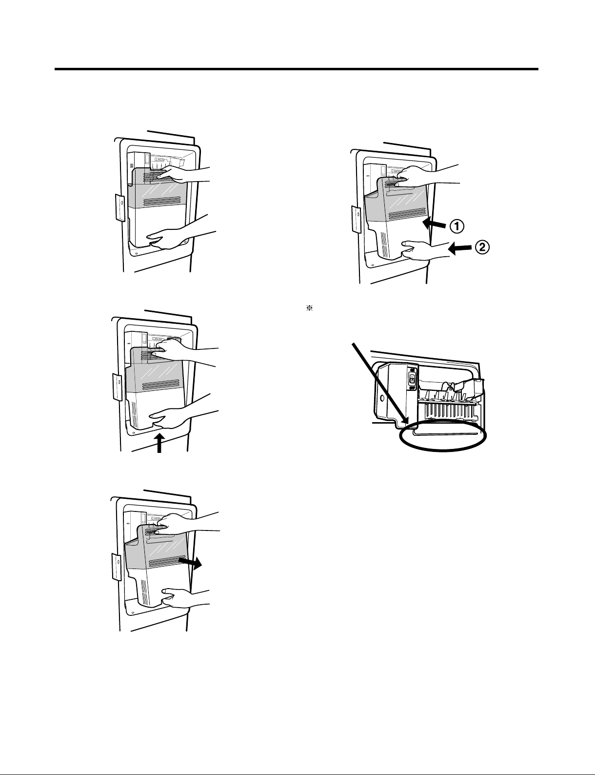
3-17 HOW TO REMOVE A DOOR ICE BIN
1) Grip the handles, as shown in the picture.
2) Lift the lower part slightly.
3-18 HOW TO INSERT A DOOR ICE BIN
1) Insert the Ice Bin, slightly tilting it to avoid touching the
Icemaker. (especially, ice maker lever)
Insert the ice bucket carefully avoid contacing the
automatic shut off arm.
3) Take the Ice Bin out slowly.
- 13 -
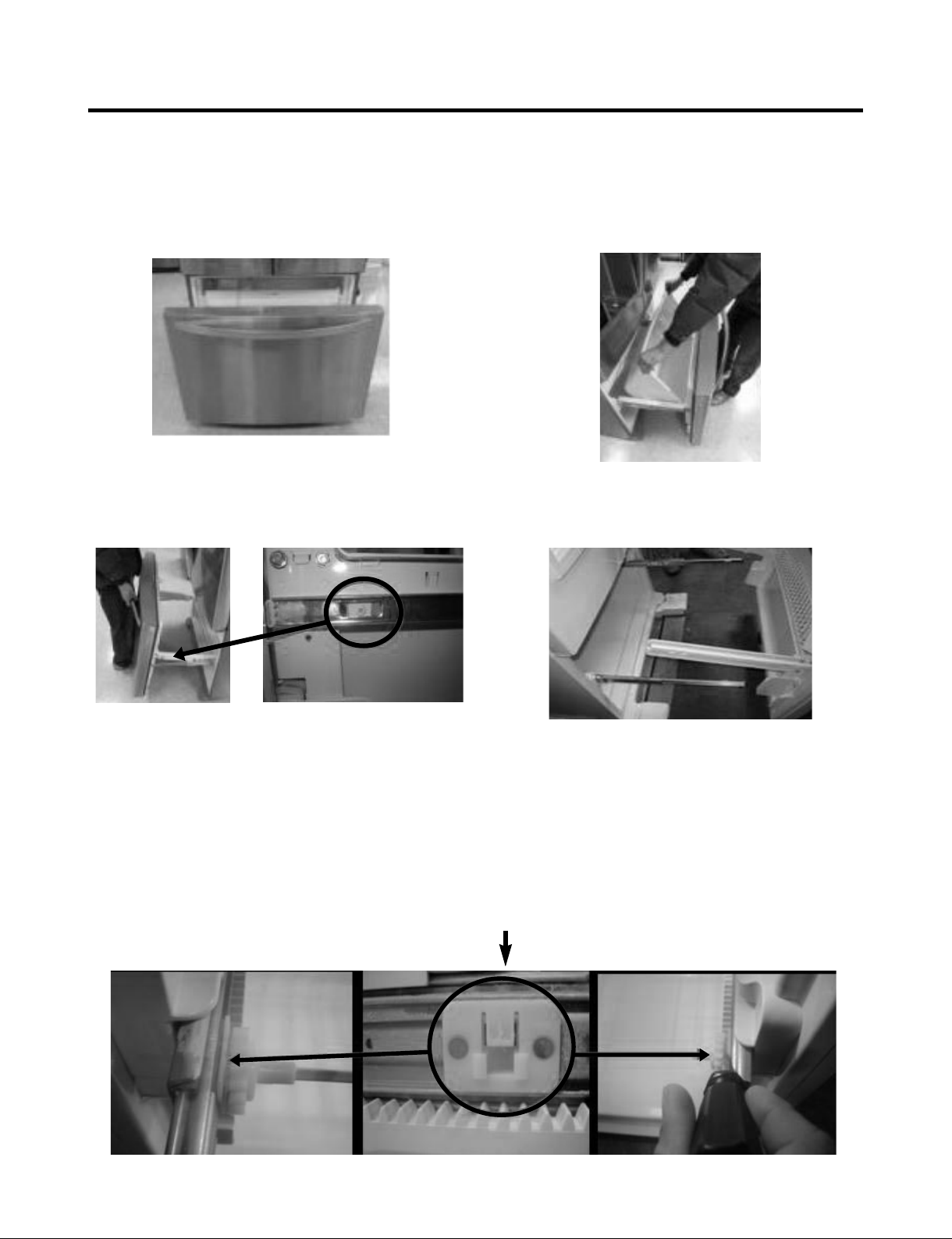
3-19 HOW TO REMOVE AND REINSTALL THE PULLOUT DRAWER
3-19-1 Follow Steps to Remove
Step 1) Open the freezer door.
Step 3) Remove the two screws from the guide rails (one
from each side).
Step 2) Remove the lower basket.
Step 4) Lift the freezer door up to unhook it from the rail
support and remove.
Pull both rails to full extension.
Step 5) First: Remove the gear from the left side first by releasing the tab behind the gear, place a screwdriver between the
gear and the tab and pull up on the gear.
Second: Remove the center rail.
Third: Remove the gear from the right side by following the same steps for the left side.
NOTE : THIS TAB MUST BE PUSHED IN TO RELEASE THE GEAR.
- 14 -
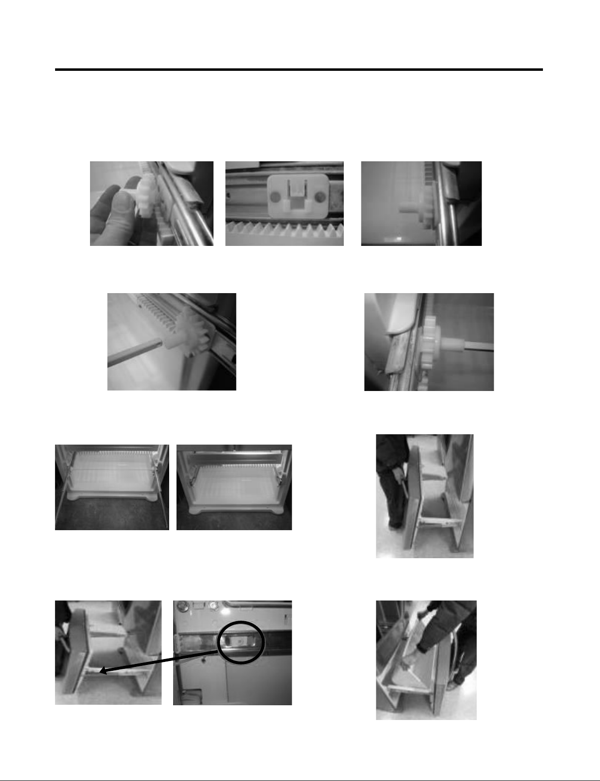
3-19-2 Follow Steps to Reinstall
Step 1) Reinstall the right side gear into the clip.
Step 2) Insert the rail into the right side gear. Gears do not
need to be perpendicular to each other.
Step 4) The rail system will align itself by pushing the rails
all the way into the freezer section.
Pull the rails back out to full extension.
Step 3) Insert the rail into the left side gear, and insert the
gear into the clip.
Step 5) Reinstall the freezer door by inserting the rail tabs
into the guide rail.
Step 6) Reinstall the two screws into the guide rails
(one from each side).
Step 7) Reinstall the lower basket, and close the freezer
door.
- 15 -
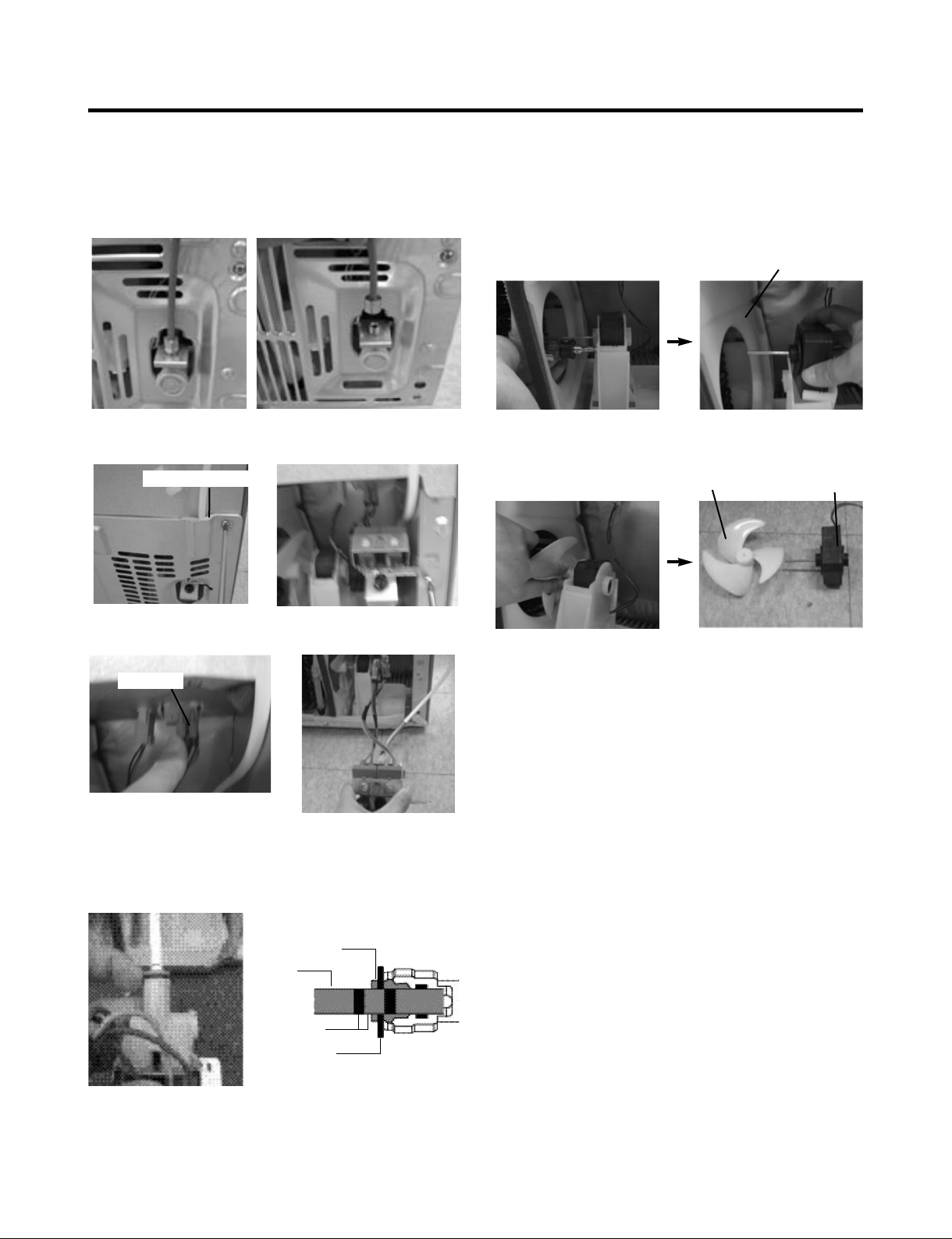
3-20 WATER VALVE DISASSEMBLY METHOD
1) Turn off the water. Then separate the water line from the
valve.
3-21 FAN AND FAN MOTOR DISASSEMBLY
METHOD
1) Using a short screwdriver, loosen one SCREW in DRAIN
PIPE ASSEMBLY and one connected to the MOTOR
COVER.
MOTOR COVER
2) Separate the Mechanical Cover and Valve Screw.
Mechanical Cover
3) Separate the housing and pull out the valve.
Housing
4) Lay a dry towel on the floor and get ready to spill water
from the water filter. Pull out the Cilp. Then press te
collet to separate the tube from the connector and pour
out the water until emptied.
2) Pull and separate the FAN ASSEMBLY and MOTOR
turning counterclockwise based on the MOTOR SHAFT.
FAN ASSEMBLY
The assembly is in the reverse order of the disassembly
and take special care for the following details.
1. Be careful not to bend the tube during assembly.
2. Press the WATER DISPENSER button until water pours
out and check for leakage in the CONNECTOR TUBE (It
differs by the water pressure but usually takes about 2
minutes until water pours out.)
MOTOR
Collet
Tube
Insert Line
Clip
- 16 -
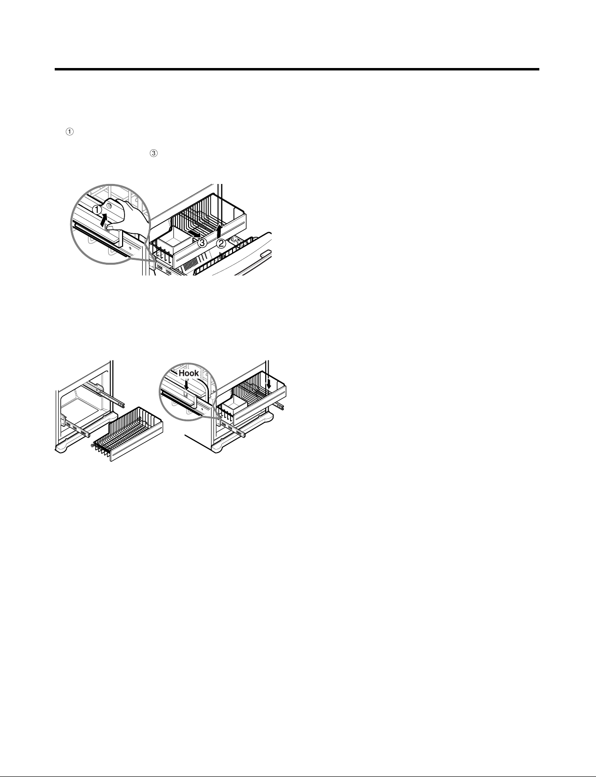
3-22 PULL OUT DRAWER
To separate the drawer, push the front left and right hooks
in
direction to pull up and remove.
Then gently lift the gear part of rear left and right side of the
drawer and pull it out in
To install, reposition the gear part of rear left and right side
of the drawer after pulling out both rails as much as
possible, and gently push down both left and right side
while checking the hook on the front part.
direction.
- 17 -
 Loading...