

Kenmore 790.7937 User Manual
Gas Range
3 c; ijL \.j i
ÜUICI€
Estufa a gas
Models, Modelos 790.7936*, 7937*
* = color number, número de color
.. ...
I##
_
www.sears.com Sears Roebuck and Co., Hoffman Estates, IL 60179 U.S.A. p/n 316417309(0408)

Table of Contents
Freestanding Range Warranty..............................................................2
IMPORTANT SAFETY INSTRUCTIONS
Protection Agreements..........................................................................6
Before Using Your Range
• Assembly of Burner Heads, Caps & Grates
Range Features
Before Setting Oven Controls..........................................................9-10
Before Setting Surface Controls
Surface Cooking..............................................................................11-13
• Operating Gas Surface Burners.................................................11
• Operating the Bridge Burner (some models)............................ 12
• Using the Griddle........................................................................ 13
Setting Warmer Drawer & Controls...............................................13-15
• Arranging Warmer Drawer Racks.............................................. 13
• Operating & Setting Warmer Drawer & Bread Proofing ... 14
• Removing & Replacing Warmer Drawer
Electronic Oven Control Pad Features
Minimum & Maximum Control Pad Settings
Setting Oven Controls
Setting the Clock......................................................................... 17
Changing between 12 or 24 Hour Display
Continuous Bake or 12 Hour Energy Saving Mode
Kitchen Timer.............................................................................. 18
Oven Lockout
Changing Temperature Display................................................. 19
Silent Control Operation..............................................................20
....
....
..............................................................
........................................................................... 8
....
...........................................................
..............................................................................
............................................
................................
.......................................................
...................................
..............................................
....................................
17-31
................................
.................
3-5
10
15
16
16
17
18
19
Saving & Recalling Recipe Settings...........................................20
Setting Preheat............................................................................21
Setting Bake
7
7
Setting Timed Bake......................................................................23
Setting Delay Start (Delayed Timed Bake).................................24
Setting Broil & Searing Grill .......................................................25
Setting Food Categories (Meats, Cakes & Breads)
Setting Convection Bake.............................................................27
Setting Convection Convert........................................................28
Setting Add 1 Minute Feature
Setting Slow Cook........................................................................29
Setting the Sabbath Feature
Setting Warm & Hold...................................................................31
Self-Cleaning...................................................................................32-34
Preparing for the Self-Clean Cycle
Setting Flex Clean (including Delay Flex Clean)..................33-34
Adjusting Oven Temperature..............................................................35
General Care & Cleaning................................................................36-40
• Cleaning Table..............................................................................36
• Oven Door Removal & Care
• Cleaning the Cooktop, Burner Heads, Caps & Grates 38-40
• Operating & Changing the Oven Light(s)
Before You Call for Service .....
Recipes for Slow Cook
Sears Service
.................................................................................
...................
.....................................................
.................................................
...........................................
........................................................
................................
....................................................
........................................................................
....
..................................................................back cover
22
26
28
30-31
32
37
40
41 -42
43
Free-Standing Range Warranty
FULL ONE YEAR WARRANTY ON ALL PARTS
For one yearfrom the date of purchase, when installed and operated according to the Installation Instructions and Use &
Care Guide, if any part of this range fails due to a defect in material or workmanship, Sears will repair or replace it, at our
option, free of charge.
ADDITIONAL FOUR-YEAR LIMITED WARRANTY ON RANGE PARTS
For the second through the fifth year from the date of purchase, when installed and operated according to the
Installation Instructions and Use & Care Guide, Sears will supply the following range parts free of charge if they
fail for the reasons listed below. Customer must pay labor cost of installation.
• Cooktop glass if it fails due to thermal shock
• Cooktop elements if they are defective
• Rubber seal if it cracks between the cooktop glass and the porcelain edge.
What Sears will not cover;
• Failure of the product if it is abused, misused, or used for other than the intended purpose,
• Damage to the cooktop glass caused by the use of cleaners or utensils other than the recommended cleaning cream
and tools.
• Damage to the cooktop glass caused by hardened spills of sugary materials (including starches from vegetables or
pastas) or melted plastic that are not cleaned according to the directions in the Use & Care Guide.
• Repairs to parts or systems resulting from unauthorized modifications made to the appliance.
If this product is subjected toother than private residential use, all warranty coverage is effective for only 90 days,
WARRANTY SERVICE IS AVAILABLE BY CONTACTING SEARS AT
1-800-4-MY-HOME®.
This warranty gives you specific legal rights, and you may also have other rights which vary from state to state.
Sears, Roebuck and Co., Dept. 817WA, Hoffman Estates, IL 60179
Important Safety Instructions
Read all instructions before using this appliance. Save these instructions for future reference.
This manual contains important safety symbols and instructions. Please pay attention to these symbols and follow all instructions given.
À WARNING
iOk CAUTION
À WARNING
I This symbol will: help alert you to situations that may cause serious bodily harm, death or property damage.
This symbol will help alert you to situations that may cause bodily injury or property damage.........................
If the information in this manual is not
followed exactly, a fire or explosion may resuit
causing property damage, personal injury or death.
FOR YOUR SAFETY;
— Do not store or use gasoline or other fiammabie
vapors and liquids in the vicinity of this or any
otherappliance.
— WHAT TO DO IF YOU SMELL GAS:
• Do nottryto lightanyappilance.
• Do not touch any electrical switch; do not use
any phone in your building.
• Immediately call your gas supplier from a
neighbor's phone. Follow the gas supplier’s
instructions.
• If you cannot reach your gas supplier, cal! the
fire department.
— Installation and service must be performed by a
qualified installer, servicer or the gas supplier.
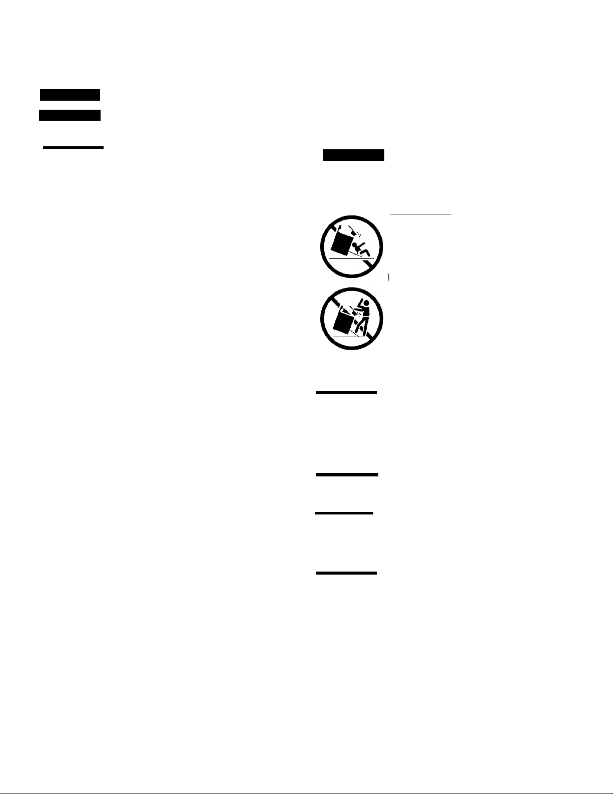
^WARNING
All ranges can tip.
Injury to persons could result.
Install anti-tip device packed with range.
See Installation Instructions.
Awarning
To reduce the risk of
tipping, the rangemust be secured by
properly installed anti-tip bracket provided
with the range. To check if the bracket is
installed properly, visually check that rear
eveling leg is inserted into and fully
secured by the anti-tip bracket by
removing lower panel or storage drawer.
For models with a warmer drawer, grasp
the top rear edge of the range and
carefully attempt to tilt it forward. Refer to
the installation instructions for proper anti
tip bracket installation.
• Remove all tape and packaging before using the range.
Destroy the carton and plastic bags after unpacking the range.
Never allow children to play with packaging material.
• Proper Installation—Be sure your appliance is properly
installed and grounded by a qualified technician in
accordance with the National Fuel Gas Code ANSI Z223.latest edition, or in Canada CAN/CGA B149.1, and CAN/CGA
B149.2, and the the National Electrical Code ANSI/NFPA
No.70-latest edition, or in Canada CSA Standard C22.1,
Canadian Electrical Code, Part 1, and local code
requirements. Install only per installation instructions
provided in the literature package for this range.
Ask your Sears dealer to recommend a qualified technician
and an authorized Sears repair service. Know how to
disconnect the power to the range at the circuit breaker or
fuse box in case of an emergency.
• User servicing—Do not repair or replace any part of the
appliance unless specifically recommended in the manuals.
All other servicing should be done only by a qualified
technician, This may reduce the risk of personal injury and
damage to the range.
• Never modify or alter the construction of a range by
removing leveling legs, panels, wire covers, anti-tip brackets/
screws, or any other part of the product.
À WARNING
drawers of this range can result in serious injuries and also
cause damage to the range. Do not allow children to climb or
play around the range. The weight of a child on an open door
may cause the range to tip, resulting in serious burns or other
injury.
WARNING
equipped) for storage.
^CAUTION
the cabinets above a range or on the backguard of a range.
Children climbing on the range to reach items could be
seriously injured.
À WARNING
Heating the Room.
• Storage in or on Appliance—Flammable materials should
not be stored in an oven, warmer drawer, near surface
burners or in the storage drawer. This includes paper, plastic
and cloth items, such as cookbooks, plasticware and towels,
as well as flammable liquids. Do not store explosives, such as
aerosol cans, on or near the range.
I Stepping, leaning or sitting on the doors or
Do not use the oven or warmer drawer (if
Do not store items of interest to children in
Never Use Your Appliance for Warming or

Important Safety Instructions
• Do Not Leave Children Alone—Children should not be left
alone or unattended in the area where appliance is in use.
They should never be allowed to sit or stand on any part of the
appliance.
• DO NOTTOUCH SURFACE BURNERS, AREAS NEARTHESE
BURNERS,OVEN BURNERSORINTERIORSURFACESOFTHE
OVEN. Both surface and oven burners may be hot even though
flames are not visible. Areas near surface burners may
become hot enough to cause burns. During and after use, do
not touch, or let clothing or other flammable materials touch
these areas until they have had sufficient time to cool. Among
these areas are the cook top, surfaces facing the cook top, the
oven vent openings and surfaces near these openings, oven
door and window.
• Wear Proper Apparel—Loose-fitting or hanging garments
should never be worn while using the appliance. Do not let
clothing or other flammable materials contact hot surfaces.
• Do Not Use Water or Flour on Grease Fires—Smother the
fire with a pan lid, or use baking soda, a dry chemical or
foam-type extinguisher.
• When heating fat or grease, watch it closely. Fat or grease
may catch fire if allowed to become too hot.
• Use Only Dry Potholders—Moist or damp potholders on hot
surfaces may result in burns from steam. Do not let
potholders touch hot heating burners. Do not use a towel or
other bulky cloth instead of a potholder.
• Do Not Heat Unopened Food Containers—Buildup of
pressure may cause container to burst and result in injury.
• Remove the oven door from any unused range if it is to be
stored or discarded.
IMPORTANT—ELECTRIC IGNITION MODELS ONLY: Do not
attempt to operate the oven during a power failure. If the power
fails, always turn off the oven. If the oven is not turned off and
the power resumes, the oven will begin to operate again. Once
the power resumes, reset the clock and oven function.
• Protective Liners—Do not use aluminum foil to line surface
burner pans, or oven bottom, except as suggested in this
manual. Improper installation of these liners may result in risk
of electric shock, or fire.
• Glazed Cooking Utensils—Only certain types of glass, glass/
ceramic, ceramic, earthenware, or other glazed utensils are
suitable for cooktop service without breaking due to sudden
change in temperatures. Check the manufacturer’s
recommendations for cooktop use.
IMPORTANT INSTRUCTIONS FOR USING YOUROVEN
• Use Care When Opening Oven Door or Warmer Drawer—
Stand to the side of the range when opening the door of a hot
oven. Let hot air or steam escape before you remove or
replace food in the oven.
• Keep Oven Vent Ducts Unobstructed. The oven vent is
located below the backguard. Touching the surfaces in this
area when the oven is operating may cause severe burns.
Also, do not place plastic or heat-sensitive items on or near
the oven vent. These items could melt or ignite.
• Placement of Oven Racks, Always place oven racks in
desired location while oven is cool. If rack must be moved
while oven is hot use extreme caution. Use potholders and
grasp the rack with both hands to reposition. Do not let
potholders contact the hot heating elements in the oven.
Remove all utensils from the rack before moving.
• Do not use the broiler pan without its insert. The broiler pan
and its insert allow dripping fat to drain and be kept away from
the high heat of the broiler.
• Do not cover the broiler insert with aluminum foil. Exposed
fat and grease could ignite.
• Cold temperatures can damage the electronic control. When
using the appliance for the first time, or when the appliance
has not been used for an extended period of time, be certain
the unit has been in temperatures above 32°F (0°C) for at
least 3 hours before turning on the power to the appliance.
IMPORTANT INSTRUCTIONS FOR USING
YOUR COOKTOP
^WARNING
it does not extend beyond the edge of the utensil. The use of
undersized utensils will expose a portion of the burner flame to
direct contact and may result in ignition of clothing. Proper
relationship of utensil to flame will also improve efficiency.
• Know which knob controls each surface burner. Place a
pan of food on the burner before turning it on, and turn the
burner off before removing the pan.
•Always turn knob to the full LITE position when igniting top
burners. Visually check that burner has lit. Then adjust the flame
so it does not extend beyond the edge of the utensil.
• Utensil Handles Should Be Turned Inward and Not Extend Over
Adjacent Surface Burners—To reduce the risk of burns, ignition
of flammable materials, and spillage due to unintentional contact
with the utensil, the handle of the utensil should be positioned so
that it is turned inward, and does not extend over adjacent surface
burners.
• Never Leave Surface Burners Unattended at High Heat
Settings—Boilovers cause smoking and greasy spillovers that
may ignite, or a pan that has boiled dry may melt.
Use Proper Flame Size—Adjust flame size so
IMPORTANT INSTRUCTIONS FOR CLEANING
YOUR RANGE
• Clean the range regularly to keep all parts free of grease
that could catch fire. Pay particular attention to the area
underneath each surface element. Do not allow grease to
accumulate. Refer to the range manufacturer’s instructions for
cleaning.
• Kitchen cleaners and aerosols—Always follow the
manufacturer’s recommended directions for use. Be aware
that excess residue from cleaners and aerosols may ignite
causing damage and injury.
SELF CLEANING OVENS
• Clean in the self-cleaning cycle only the parts listed in this
Use & Care Guide. Before self cleaning the oven, remove the
broiler pan and any utensils or foods from the oven.
• Do Not Use Oven Cleaners—No commercial oven cleaner or
oven liner protective coating of any kind should be used in or
around any part of the oven.
• Do Not Clean Door Gasket—The door gasket is essential for
a good seal. Care should be taken not to rub, damage or
move the gasket.
Important Safety Instructions
FOR CERAMIC-GLASS COOK TOP MODELS (some models)
• Do Not Cook on Broken Cook Top—If cook top should break, cleaning solutions and spillovers may penetrate the broken cook top
and create a risk of electric shock. Contact a qualified technician immediately.
• Clean Cook Top with Caution—If a wet sponge or cloth is used to wipe spills on a hot cooking area, be careful to avoid a steam burn.
Some cleaners can produce noxious fumes if applied to a hot surface.
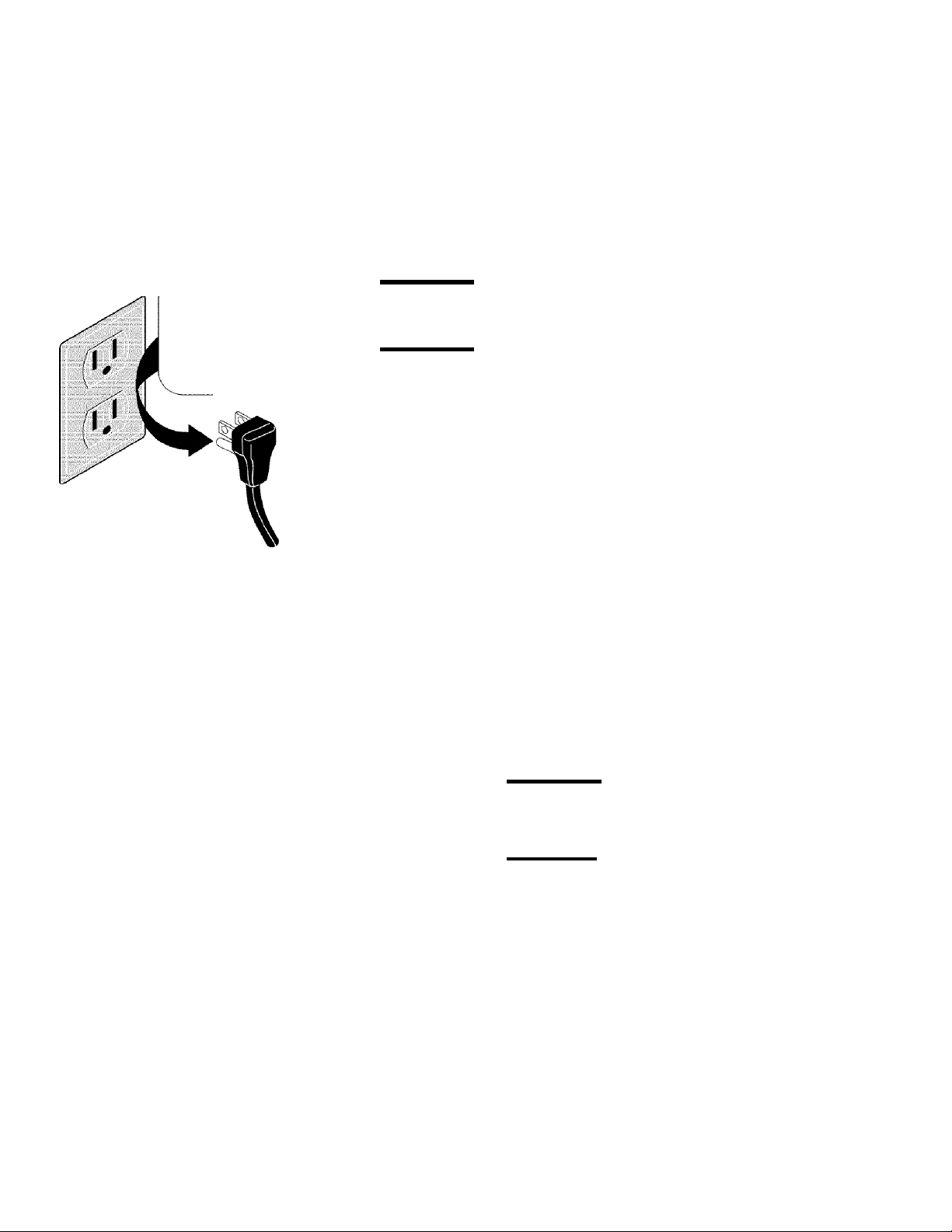
Grounding type
wall receptacle
Do not, under any
circumstance, cut,
remove, or bypass
the grounding prong.
Power supply cord
with 3-prong
grounding plug
Grounding Instructions
{electric ignition models only)
A WARNING
an extension cord, or remove grounding prong from electrical power cord.
Failure to follow this warning can cause serious injury, fire or death.
A WARNING
your protection against shock hazard and should be plugged directly into a
properly grounded receptacle. DO NOT cut or remove the grounding prong from
this plug.
For personal safety, the range must be properly grounded. For maximum safety,
the power cord must be plugged into an electrical outlet that is correctly polarized
and properly grounded.
If a 2-prong wall receptacle is the only available outlet, it is the personal
responsibility of the consumer to have it replaced with a properly grounded 3prong wall receptacle installed by a qualified electrician.
See the INSTALLATION INSTRUCTIONS packaged with this range for complete
installation and grounding instructions.
Avoid fire hazard or electrical shock. Do not use an adapter plug,
This appliance is equipped with a 3-prong grounding plug for
Important Safety Notice
The California Safe Drinking Water and Toxic Enforcement Act requires the Governor of California to publish a list of substances
known to the state to cause cancer, birth defects or other reproductive harm, and requires businesses to warn customers of
potential exposure to such substances.
Conversion to Liquefied Petroleum Gas (or L.P. Gas)
The natural gas range is designed to allow for conversion to
Liquefied Petroleum (L.P.) Gas.
If L.P. conversion is needed, contact 1 -800-4-MY-HOME®for
assistance. The L.P. Conversion Kit is provided with this range
and is located on the left lower REAR (back side) panel of the
range. Before installing the kit be sure to follow the L.P.
Installation Instructions carefully.
Awarning
shock may occur if the range is not installed by a
qualified installer or electrician.
AWARNtNG
required in order for this appliance to satisfactorily meet
the application needs must be made by Sears Service.
Personal injury or death from electrical
I Any additions, changes or conversions

PROTECTION AGREEMENTS
In the U.S.A.
Master Protection Agreements
Congratulations on making a smart purchase. Your
new Kenmore® product is designed and manufactured
for years of dependable operation. But like all products,
it may require preventive maintenance or repair from
time to time. That’s when having a Master Protection
Agreement can save you money and aggravation.
Purchase a Master Protection Agreement now and
protect yourself from unexpected hassle and
expense.
The Master Protection Agreement also helps extend
the life of your new product. Here’s what’s included in
the Agreement:
0 Expert service by our 12,000 professional repair
specialists
0 Unlimited service and no charge for parts and
labor on all covered repairs
0 “No-lemon” guarantee - replacement
of your covered product if four or more product
failures occur within twelve months
0 Product replacement if your covered product
can’t be fixed
0 Annual Preventive Maintenance Check at your
request - no extra charge
0 Fast help by phone - phone support from a Sears
technician on products requiring in-home repair, plus
convenient repair scheduling
0 Power surge protection against electrical
damage due to power fluctuations
0 Rental reimbursement if repair of your covered
product takes longer than promised
In Canada
Maintenance Agreements
Your purchase has added value because you
can depend on Sears HomeCentral®for service.
With over 2400 Service Technicians and more than a
million parts and accessories, we have the tools,
parts, knowledge and skills to ensure our pledge:
We Service What We Sell.
Your Kenmore® product is designed, manufactured
and tested to provide years of dependable operation.
But like all products, it may require service from time to
time. The Sears Maintenance Agreement offers you an
outstanding service program, affordably priced.
The Sears Maintenance Agreement:
• Is your way to buy tomorrow’s service at today’s
price
• Eliminates repair bills resulting from normal wear
and tear
• Provides phone support from a Sears technician on
products requiring in-home repair
• Even if you don’t need repairs, provides an annual
Preventive Maintenance Check, at your request, to
ensure that your product is in proper running condition.
Some limitations apply. For more Information
about Sears Canada Maintenance Agreements,
call 1-800-361-6665
Once you purchase the Agreement, a simple phone
call is all that it takes for you to schedule service. You
can call anytime day or night, or schedule a service
appointment online.
Sears has over 12,000 professional repair specialists,
who have access to over 4.5 million quality parts and
accessories. That’s the kind of professionalism you
can count on to help prolong the life of your new
purchase for years to come. Purchase your Master
Protection Agreement today!
Some limitations and exclusions apply.
For prices and additional information call
1-800-827-6655.
Sears Installation Service
For Sears professional installation of home
appliances, garage door openers, water heaters,
and other major home items, in the U.S.A. call
1-800-4-MY-HOME®
REV. 030509
Before Using Your Range
Assembly of Burner Heads & Burner Caps (for Deep Well Cooktop models only)
Your range is shipped with the Burner Heads and Burner Caps in the correct locations. Packing material is located between
the Burner Heads and Burner Skirts.
1. Be sure to follow the Installation Instructions before
installing and using your new range.
2. Remove all packing tape from cooktop area. Remove all
Burner Caps and Burner Heads.
3. Discard all packing material located under Burner Heads.
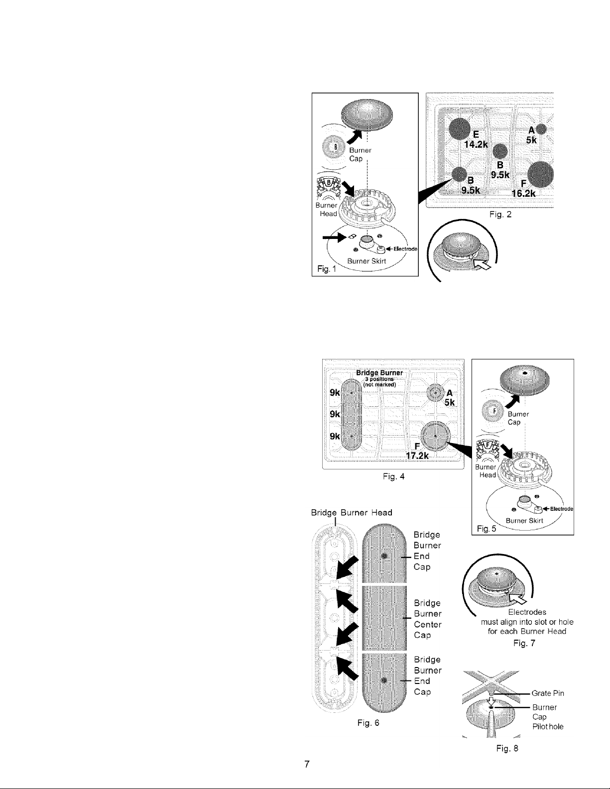
4. To replace Burner Heads & Caps, match the letters
located under center of Burner Caps with the letters
located inside Burner Heads (Fig. 1).
5. Match the letters stamped on Burner Skirts with Burner
Heads and Burner Caps (See Fig. 1). Replace the Burner
Heads and Caps on cooktop (See Fig. 2). Carefully align
the Electrodes into slot or hole of each Burner Head (Fig,
3). Note: The Burner Heads should sit flat on Cooktop
Burner Skirts.
6. Unpack Burner Grates and position on the cooktop.
Fig. 3 Burner Head
Assembly of Burner Heads & Burner Caps (for Ceramic Glass Cooktop models only)
Your range is shipped with the Burner Heads and Burner Caps in the correct locations. Packing material is located between
the Burner Heads and Burner Skirts.
Electrodes must
align into slot or hole for each
ffl
1. Be sure to follow the Installation Instructions before
installing and using your new range.
2. Remove all packing tape from cooktop. Remove Burner
Caps and Burner Heads (See Fig. 4),
3. Discard all packing material located under all Burner
Heads.
4. To replace Burner Heads & Caps, match the letters
located under center of Burner Caps with the letters
located inside Burner Head (only positions A & F are
marked with letters - See Fig. 5). Place all Burner Heads
& Caps on the cooktop (See Fig, 4) while carefully
aligning the Electrodes into slots or holes of the Burner
Heads (Fig. 7). Note: The Burner Heads should sit flat on
Cooktop Burner Skirts.
5. Replace Bridge Burner Caps. These include one Bridge
Burner Center Cap (rectangular shaped) and the two
Bridge Burner End Caps (The Bridge Burner End Caps will
fit either the front or rear Bridge Burner Head locations).
Make sure that the tabs located under the Bridge Burner
Caps fall into the slots located in the Bridge Burner Head
(See arrows in Fig. 6) and that all the Bridge Burner Caps
lie flat and evenly on the Bridge Burner Head,
6. Unpack Burner Grates. NOTE: Do not force End Burner
Grates down on cooktop. Be careful to line up the 2 Grate
Pins located on each of the 2 End Burner Grates into the
Pilot holes located on top of the Burner Caps (See Fig. 8).
Position Burner Grates on cooktop and check that all the
Burner Grate legs lie on the glass surface.
7. Place Center Burner Grate between the end Burner
Grates.

Range Features
Your Elite Gas Range Features Include:
1. Electronic Oven Control with Kitchen Timer.
2. Glass Touch Sensitive Control Panel.
3. Left Front Burner Valve & Knob.
4. Left Rear Burner Valve & Knob or Bridge Burner Valve & Knob
{some models).
5. Center Burner Valve & Knob (some models).
6. Right Rear Burner Valve & Knob.
7. Right Front Burner Valve & Knob.
8. Easy to clean Deep Weil Cooktop (some models) or Ceramic
Gas through Glass Cooktop (some models).
9. Dishwasher safe Burner Grates (colors vary).
10. Dishwasher safe Center Burner Grate (colors vary).
11. Warmer Drawer Control & Indicator Light.
12. Seif-Clean Oven Door Latch.
13. Automatic Oven Door Light Switch.
14. Dual Oven Interior Lights with Shields.
15. Self-Cleaning Oven interior.
16. Convection Bake Fan & Cover.
17. Adjustable Porcelain Coated Oven Racks (includes Handle &
Half Oven Racks).
Large 1 piece Oven Door Handle (styles & colors vary with
18.
model).
Full width Oven Door (styles & colors vary with model).
19.
Warmer Drawer with Handle & Warmer Drawer Rack.
20.
21.
5,000 BTU Simmer Burner.
22. 9,500 BTU Center Burner (some models).
23. 9,500 BTU Power Burner.
14.200 BTU Power Burner.
24.
16.200 BTU Power Burner.
25.
*9,000 BTU Burners ( When used as a Bridge Burner with all 3
26.
burners combined is 27,000 BTU).
27. 17,200 BTU Power Burner
(some models).
28. Broil Pan. ^
29. Broil Pan Insert.
30. Searing Grill.
31. Roasting Rack.
32. Griddle.
31. Leveling Legs and Anti-tip
Bracket (included).
© '■ - 0 ' 0©L '■ ©
; , . @® ■
NOTES: Thefeaturesofyourrange
may vary according to model type &
color.
‘Bridge Burnerfeatured on Glass
Cooktop models only.
Vi
Deep Well Cooktop style
‘Ceramic Glass Cooktop style

Before Setting Oven Controls
OVEN VENT
Fig, 1
Fig, 2
^6
©
@
®
®
Oven Vent Location
The oven vent is located below the backguard (See Fig. 1). When the oven is on,
warm air is released through this vent. This venting is necessaryfor proper air
circulation in the oven and good baking results. DO NOT BLOCK THE VENT,
^CAUTION
Wait until the oven has completely cooled if possible. Oven racks may be HOT and
may cause burns.
I Always use pot holders or oven mitts when adjusting the oven racks.
Removing & Replacing Oven Racks
To remove, pull the rack forward until it stops. Lift up front of rack and slide out.
To replace, fit the rack onto the guides on the oven walls. Tilt the front of the rack
upward and slide the rack back into place.
Recommended Rack Positions for Broiling, Baking & Roasting:
Food Rack Position
Broiling hamburgers & steaks 1
Broiling meats, chicken or fish 1,2 or 3
Cookies, cakes, pies, biscuits
& Muffins
Frozen pies, angel food cake,
yeast, bread, casseroles, small
cuts of meat or poultry
Turkey, roast or ham 5 or 6
3 or 4
5 or 6
m
Types of Oven Racks
Flat Handle Oven Rack
Fig. 3
Your range may be equipped with one or more
of the oven rack types shown; a Porcelain
coated Flat Handle Oven Rack (Fig. 3) ora
Porcelain coated Flat Oven Half Rack (Fig.
4). The Flat Oven Half Rack has a removable
insert that can provide extra space for larger
food items. The right half rack portion may still
be used for other food items like a casserole
dish (See Fig. 4).
To remove the Half Oven Rack insert, squeeze on the left front insert side (See Fig. 5) of the rack and tilt out clockwise . To
reinstall insert rear hooks at back of insert (See 1 -Fig, 6) and lay insert down. Make sure both insert front hooks snap into
rack (See 2-Fig. 6).
Do not use cookware that extends beyond the edge of the Oven Flat Half Rack. For best results, allow 2 inches between
the pan placed on the rack and oven side or rear walls.
Before Setting Oven Controls
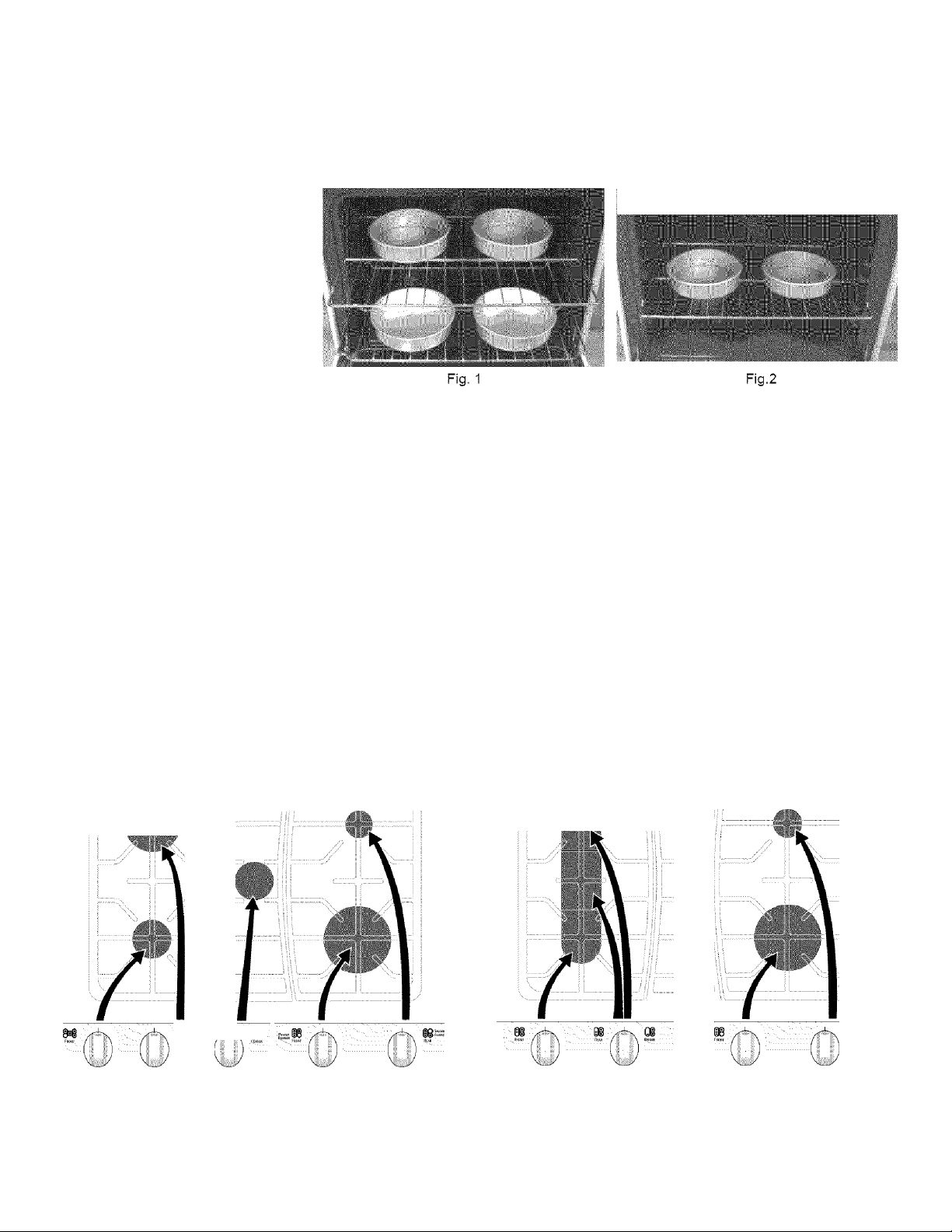
Baking Layer Cakes with 1 or 2 Oven Racks
For best results when baking cakes using 2 oven racks, place cookware on oven rack positions 2 & 5 (See Fig. 1 and Fig.
2 on page 9). For best results when using a single oven rack, place cookware on oven rack position 4 (See Fig. 2 and Fig.
2 on page page 9).
Air Circulation in the Oven
For best air circulation and baking
results allow 2-4" (5-10 cm) around
the cookware for properaircirculation
and be sure pansand cookware do not
touch each other, the oven door, sides
or back of the oven cavity. The hot air
must be able to circulate around the
pans and cookware in the oven for
even heat to reach around the food.
Before Setting Surface Controls
Control Locations of the Gas Surface Burners
(For models with a Deep Well Cooktop-See Fig. 3)
Ther SIMMER Burner is best used for simmering delicate
sauces, etc. This burner is located at the right rear burner
position on the cooktop.
The STANDARD Burners can be used for most surface
cooking needs. These burners are located at the left front
and center positions on the cooktop.
The POWER Burners are best used for bringing large
quantities of liquid rapidly up to temperature or when
preparing larger quantities of food. These burner are
located at the right front and left rear positions on the
cooktop.
■ ii i I i W111 i I 1111111
(For models with a Ceramic Cooktop-See Fig. 4)
Ther SIMMER Burner is best used for simmering delicate sauces,
etc. This burner is located at the right rear burner position on the
cooktop.
The STANDARD sized burners are used for most surface cooking
needs. These burners are located at the left front and left rear
positions on the cooktop.
The POWER Burner is best used for bringing large quantities of
liquid rapidly up to temperature or when preparing larger quantities
of food. This burner is located at the right front position on the
cooktop.
The BRIDGE Burner is best suited when using rectangular or long
shaped cookware. The left rear and left middle positions are
combined. The left front Burner may also be added for a total of 3
burners.
Q / 0 & Power
FRONT Rear CENTER Front Reas
Left Left Center Right Right Left Left Rear & Right Right
Front Rear Burner Front Rear Front Bridge Burner Front Rear
Burner Burner Burner Burner Burner , Burner Burner
Fig, 3 Fig, 4
POWER ^8^
BtlRMER
Simmer
^8^ Burner
m
Iront REAR BREORE ' FRONT
§1 n
Power ^IO
Burner
rear
Burner
10
I3ÎSS
Simmer
Surface Cooking
• Operating Gas Surface Burners
• Setting Proper Burner Flame Size
^CAUTION
items such as salt and pepper
shakers, spoon holders or plastic
wrappings on top of the range when
it is in use. These items could melt or
Do not place plastic
ignite. Potholders, towels orwood
spoons could catch fire if placed too
close to a flame.
In the event of an electrical power
outage, the surface burners can be lit
manually. To light a surface burner, hold
a lit match to the burner head, then
slowly turn the surface control knob to
LITE. After burner lights push in and turn
knob to desired setting. Use caution
when lighting surface burners manually.
/if
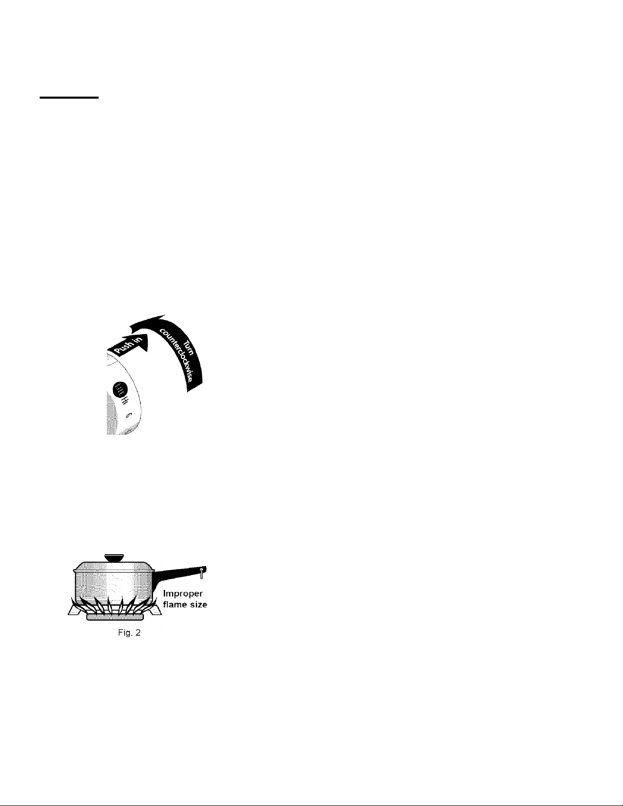
Operating the Gas Surface Burners:
1. Place cooking utensil on surface burner.
2. Push the surface control knob in and turn counterclockwise out of the
OFF position (See Fig. 1).
3. Release the knob and rotate to the LITE position. Note: All four electronic
surface ignitors will spark at the same time. However, only the burner you
are turning on will ignite.
4. Visually check that the burner has lit.
5. Push the control knob in and turn counterclockwise to the desired flame
size. The control knobs do not have to be set at a particular setting. Use
the guides and adjust the flame as needed. DO NOT cook with the surface
control knob in the LITE position (The electronic ignitor will continue to
spark if the knob is left in the LITE position).
Setting Proper Surface Burner Flame Size
For most cooking, start on the highest control setting and then turn to a
lower one to complete the process. Use the recommendations below as a
guide for determining properflame size for various types of cooking. The size
and type of utensil used and the amount of food being cooked will influence
the setting needed for cooking.
*Flame Size
High Flame
Medium Flame
Low Flame
Type of Cooking
Start most foods; bring water to a boil; pan broiling.
Maintain a slow boil; thicken sauces, gravies; steaming.
Keep foods cooking; poach; stewing.
.. ...
I##
_
Fig. 1
flame size
*These settings are based on using medium-weight metal or aluminum
pans with lids. Settings may vary when using other types of pans. The
color of the flame is the key to proper burner adjustment. A good flame is
clear, blue and hardly visible in a well-lighted room. Each cone of flame should
be steady and sharp. Adjust or clean burner ifflame is yellow-orange.
Regardless of size, always select cookware that is suitable for the amount and
type of food being prepared. Select a burner and flame size appropriate to the
pan. Never allow flames to extend beyond the outer edge of the pan.
Never extend the flame beyond the outer edge of the utensil. A higher flame
wastes heat and energy and increases your risk of being burned by the
flame (Fig. 2).
For deep fat frying, use a thermometer and adjust the surface control knob
accordingly. If the fat is too cool, the food will absorb the fat and be greasy. If
the fat is too hot, the food will brown so quickly that the center will be
undercooked. Do not attempt to deep fat fry too much food at once as the food
will neither brown nor cook properly.
11
Surface Cooking
• Setting Bridge Burner Control (some models)
• Operating the Bridge Burner (some models)
Setting the Bridge Burner (for Bridge Burner models only):
The Bridge Burner should be used with rectangular shaped cookware. Cookware
like the cast-iron Griddle that is supplied with your range is designed specifically for
best results with the Bridge Burner.
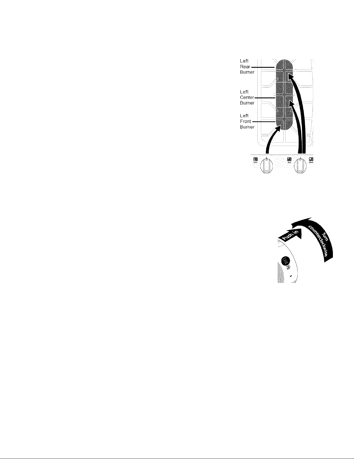
The Bridge Burner feature may be used to combine the cooking power of 2 or if
needed 3 gas surface Burners located along the left-hand side of the glass
cooktop.The left rear and left center Burners are controlled by the left rear surface
Control Knob. In addition the left front Burner may be added to the Bridge Burner
with the left front gas Control Knob (See Fig. 1).
Operating the Bridge Burner (for Bridge Burner models only):
Push the left rear surface control knob in and turn counterclockwise out of the
1.
OFF position (See Fig. 1).
Release the knob and rotate to the LITE position (See Figs. 1 & 2). Note: All
3.
electronic surface ignitors will spark at the same time, Flowever, only the
selected surface Burner will life.
Visually check that the left rear Burner has lit.
3.
Contine to rotate the gas control knob clockwise past the first LO setting to the
4.
arrowmarked BRIDGE.
Visually check that both the left rear and left center Burners are lit.
5.
When both burners are lit, continue to turn the control knob counterclockwise
6.
to adjust to the desired flame size for both burners together. Note: The
markings between the 2nd HI and LO settings on the left rear control knob
adjust the flame size for both burners. Use the guide marks between the 2nd HI
and LO settings and adjust the flame size as needed (Refer to Fig. 3).
Add the left front Burner if needed. Once lit, visually adjust the flame size of the
7.
left front Burner to match the flame size of the Bridge Burner.
Place cooking utensil centered over the left-hand cooktop surface Burner Grate.
8.
DO NOT cook with any of the surface control knobs in the LITE position (The
electronic ignitor will continue to spark if the knob is left in the LITE position).
01 mm
Front Rear Bridge
Fig. 1
Hi
Bridge
Burner
flame
adjustment
area
• •
Fig. 2
Left Rear Burner
Left Rear
Burner flame
LITE adjustment
position area
Off LO
Fig. 3 - Left Rear Bridge Burner Surface Control Knob markings
Bridge
Burner
LITE
position
Bridge
Note: If only the left rear surface Burner is needed, follow the instructions provided below.
Operating only the Left rear Gas Surface Burner (for models equipped with Bridge Burner):
1. Place cooking utensil centered overthe left-rear surface Burner Grate.
2. Push the left rear surface control knob in and turn counterclockwise out of the OFF position (See Fig. 2),
3. Release the knob and rotate to the LITE position. Note: All electronic surface ignitors will spark at the same time.
However, only the left rear Burner will ignite.
4. Visually check that the left-rear burner has lit. Adjust the flame size by turning the control knob between the first HI
and LO settings (See Fig. 3). DO NOT cook with the surface control knob in the LITE position (The electronic ignitor
will continue to spark if the knob is left in the LITE position).
12
Surface Cooking
• Care & Seasoning of the Griddle
• Using the Griddle
Care & Seasoning of the Griddle
Before first use:
• Wash Griddle in hot soapy water. Rinse and then dry completely.
• Apply a thin coat of vegetable oil to the entire surface (front and back of griddle).
• Preheat your oven to 350°F , Place the griddle on the upper rack in your oven.
• Bake griddle for 1 hour at 350°F, then turn oven OFF and let cool before removing.
• The surface may appear to have a tacky feel to it from the seasoning process. If
desired, wash the griddle in hot soapy water, rinse well, and dry completely.
After each use:
• To prevent rusting, store in a dry place and keep uncovered.
• After each use, clean with a stiff brush and hot water only.
• DO NOT CLEAN GRIDDLE IN DISHWASHER.
• Dry Immediately and apply a light coating of vegetable oil to griddle before storing.
Using the Griddle:
• Place either side of the griddle centered over the left side gas burners or over the
Bridge Burner (some models). For location refer to Fig. 1.
• Preheat the griddie for 5 minutes on medium to medium low setting. Slow
preheat ensures even heat distribution during the cooking process.
• DO NOT preheat the griddle on HI setting. Preheating on HI may warp the griddle
and prevent even heat distribution.
Fig. 1
■ ■■
z
o
f
fl
Setting Warmer Drawer Controls
• Arranging Warmer Drawer Racks
• Using the Warmer Drawer
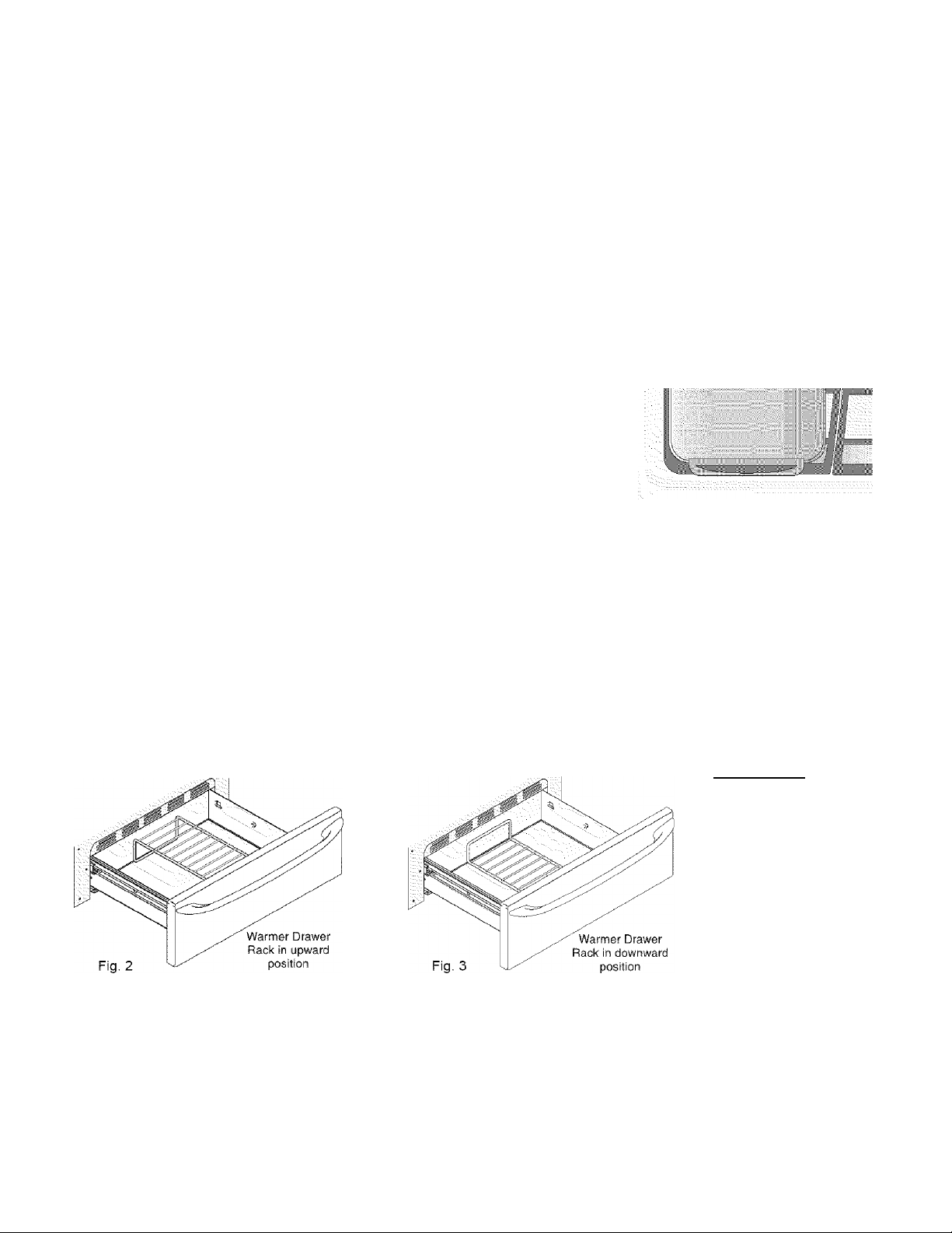
Arranging Warmer {Warm & Ready™) Drawer Rack Positions
The rack can be used in two ways:
• In the upward position (Fig, 2) to allow low profile food items to be placed both under and on top of the rack (for
example, rolls or biscuits on top of the rack and a casserole dish underneath).
• In the downward position (Fig. 3) to allow you to place light weight food items and empty dishware (for example, rolls
or pastries and dinner plates) on the rack.
^CAUTION
potholders or oven mitts
when removing food from
the Warmer Drawer as
cookware and plates will
be hot and you can be
burned.
Using the Warmer Drawer
The purpose of the Warmer Drawer is to keep hot cooked foods at serving temperature. Always start with hot food. It is not
recommended to heat cold food in the Warmer Drawer. All food placed in the Warmer Drawer should be covered with a lid
or aluminum foil to maintain quality.
Always use
Do not use plastic wrap to cover food. Plastic may melt onto the drawer and be very difficult to clean. Use only
utensils and cookware recommended for oven use in the Warmer Drawer.
Note: The Warmer Drawer wii! not operate during the Self-Clean cycle.
13

Setting Warmer Drawer Controls
• Warmer Drawers Bread Proofing Indicator Lights
• Setting Warmer Drawer S Bread Proofing Controls
• Warmer Drawer Food Temperature Settings
Warmer (Warm & Ready™) Drawer & Bread Proofing Indicator Lights
The control and indicator lights for the Warmer Drawer and Bread Proofing features are located on the control panel. The
indicator lights will turn ON when the control is set, and remain ON until the controls are turned OFF.
To Set the Warmer Drawer & Bread Proofing Controls:
1. Touch the pad at the Warmer Drawer control position. The Warmer
Drawer indicator light will flash. Note: If no further pads are touched within 25
seconds the request to power the Warmer Drawer ON will clear.
2. Set the desired power level. Touch Hi once to turn ON the power level for
HI (Fig. 2) or Lo to turn ON the power level for LO (Fig. 4). The Warmer
Drawer indicator light will glow steady indicating the Warmer Drawer is ON,
Each touch of the Lo or Hi pads will decrease or increase through
3.
6 power levels from HI (Fig, 2) to MED (Fig. 3) to LO (Fig. 4) and to the Bread
Proofing feature (Fig. 5). If the Warmer Drawer is set at the LO setting and the
Lo pad is touched again the Bread Proofing feature will be turned ON (The
Bread Proof indicator light will glow steady indicating the Bread Proofing feature
in ON (See Fig. 5 & bread dough preparation instructions on this page). To return
to standard Warmer Drawer settings touch Ht pad at least once. Note: For
best results, preheat the Warmer Drawer before adding the food or bread dough.
An empty drawer will preheat in approximately 15 minutes.
When the food or dough is ready for removal, touch the pad once to turn
the Warmer Drawer or Bread Proof feature OFF. The Warmer Drawer indicator
light will turn OFF.
Hl<
MED
Lo <
Warmer
Drawer
Hi «>
On/Oi I
Fig. 1
I
Proof
Bread
o
Hi
o
m I ^
MED® I Med®
Proof | ®
lo& o I Lo • o
Bread I i „ „ Bread
Fig. 2
Fig.3
Warmer Drawer Food
Temperature Settings
Use the recommended Warmer Drawer
food temperature settings table (See Fig,
6). If a particular food is not listed, start
with the MED setting. If more crispness is
desired, remove the lid or aluminum foil
from the food.
Most foods can be kept at serving
temperatures on the MED setting. When a
combination of foods are to be kept warm
(for instance, a meat with 2 vegetables and
rolls), use the HI setting. To avoid heat
loss, do not open the Warmer Drawer
repeatedly while in use.
Warmer Drawer Recommended
Food Settings Table
Food Item Setting
Bacon HI
Hamburger Patties HI
Poultry HI
Pork Chops HI
Fried Foods HI
Pizza HI
Gravies MED
Casseroles MED
Eggs
MED
Roasts (Beef, Pork, Lamb) MED
Vegetables MED
Biscuits MED
Rolls, hard MED
Pastries MED
Rolls (soft) LO
Empty Dinner Plates LO
Fig. 6
14
Hio
o
Medo
o
Lo ®
Fig,
Proof
Bread I
^ 1
4 <
Hi
1
I
I
o
Medo
o
Loo
Fig.
o
Proof
Bread
 Loading...