

Page 1
Owner’s Manual
KGiimorG
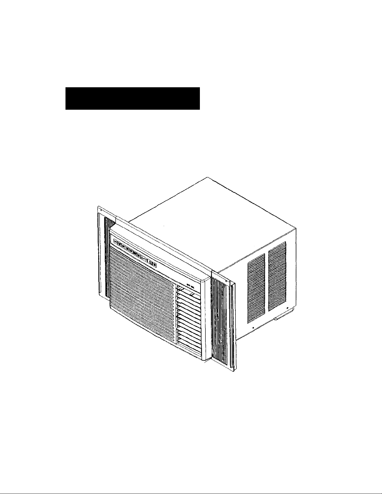
Room Air Conditioner
Model Numbers 78079,70089,70129,78189
A CAUTION
Read and follow all safety rules and
operating instructions before using
this product.
Sears, Roebuck and Co., Hoffman Estates, IL 60179 U.S.A.
Safety
Installation
Operation
Maintenance
Troubleshooting
Page 2

Contents
Warranty......................................................................... 2
Safety Instructions..........................................................3
Recognize Safety Symbols, Words, and Labels
Important Safety Information
Model Identification...................................................... 4
Parts and Feature Identification
Sizing Instructions..........................................................5
Installation.......................................................................6
Installing Room Air Conditioners
Electrical Requirements
Window Installation Instructions—7000 and 9000 Btu
Unit (Model 78079,70089).....................................7
Window Installation Instnjctions—12000, and 18000
Btu Units
(Models 70129,78189)
Through-tiie-Wall Installation—12000, and 18,000 Btu
Units
(Models 70129, and 78189)
Controls........................................................................ 20
Operating Instructions.................................................21
Before Turning Air Conditioner On........................21
....................................
...............................
.............................
...........................................
........................................
................................
......
12
17
Warranty
Normal Cooling Mode
Smart Set Mode
3
3
4
6
6
Power Saver Pius Mode...........................................21
Fan Only Mode (No Cooling)...................................21
Delay Start Operation
Adjusting Airflow Direction
Energy Saving Tips
Normal Operating Sounds
Care and Maintenance
Maintenance Schedule
Maintenance Procedures
Cleaning Air Discharge Louvers, Return Air Grille, and
Electronic Control
Evaporator Coil, Condenser Coil, and Base Pan
Maintenance
Outer Case Maintenance..........................................25
Troubleshooting
Accessories
Ordering Replacement Parts
Assistance and Service
Service
..............................................
......................................................
...............................................
.....................................22
..................................................
.......................................
..................................................
.............................................
.........................................
...............................................
........................................................
............................................................
.............................................................
...................................
................................................
.......................................................................27
21
21
22
22
23
23
23
24
24
25
26
27
27
27
Full One Year Warranty on Air Conditioner
For one year from the date of purchase, when this Kenmore Room Air Conditioner is operated and maintained
according to the instructions furnished with it. Sears will repair air conditioner free of charge if it is defective in
material or workmanship.
Full Five Year Warranty on Sealed Refrigeration System
For five years from the date of purchase, when this Kenmore Room Air Conditioner is operated and maintained
according to the instructions furnished with it. Sears will repair the air conditioner sealed system (consisting of
compressor motor, connecting tubing, evaporator coil tubing, and condenser coil tubing) free of charge, if
defective in material or workmanship.
Warranty Service
Warranty service is available by contacting the nearest Sears Service Center in the United States.
Warranty coverage applies oniy to air conditioners used for non-commercial, private household purposes.
This warranty applies only while this product is in use in the United States.
This warranty gives you specific legal rights, and you may also have other rights, which vary from state to state.
Sears, Roebuck and Co., Dept. 81 TWA, Hoffman Estates, IL 60179
Before continuing, please complete the information below. Model number and serial number information can be
found on identification plate located behind air filter. Should air conditioner ever require service, the following
information will speed the process.
Model Number: 596. ____________________________
Serial or S/N Number:________________________________
Date of purchase:
Store location: ^_______________________________
Keep this manual and your sales receipt together for future reference or if warranty service is required.
_______________________________
To prevent unnecessary service calls, review troubleshooting tips in this manual before calling for service.
_
_
Page 3
Safety Instructions
Recognize Safety Symbols, Words, and Labels
The following symbols and labels are used throughout this manual to indicate immediate or potential safety hazards.
Owner's responsibility is to read and comply with all safety information and instructions accompanying these
symbols. Failure to heed safety information increases risk of personal injury, property damage, and/or product
damage.
A DANGER
DANGER—Immediate hazards which WILL result in severe personal injury or death.
A WARNING
WARNING—Hazards or unsafe practices which COULD result in severe personal injury or death.
À CAUTION
CAUTION—Hazards or unsafe practices which COULD result in minor or moderate personal injury, product
damage, or property damage.
mportant Safety Information
A WARNING
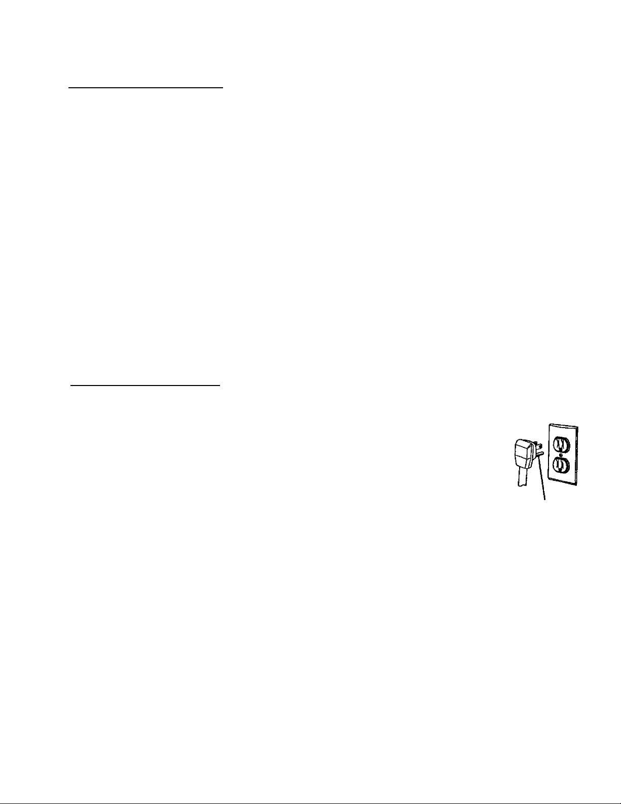
To avoid risk of personal injury or death due to electrical shock:
• Air conditioners covered in this manual are equipped with a three-prong grounding plug for
protection against possible shock hazards. DO NOT, under any circumstances, alter
grounding plug on air conditioner.
- If two-prong (non-grounding) wall receptacle is encountered, have qualified electrician
replace it with properly grounded wall receptacle meeting National Electrical Code and
all applicable local codes and ordinances.
- Airconditioner must be grounded at all times.
• Do not remove warning tag from power cord.
- Do not use a two-prong adapter with this air conditioner.
• Do not use an extension cord with this air conditioner.
A CAUTION
To avoid risk of personal injury, property damage, or product damage due to weight of air conditioner and sharp
edges that may be exposed:
- Air conditioners covered in this manual pose excessive weight hazard. Two or more people are needed to
move and install air conditioner. To prevent injury or strain, use proper lifting and carrying techniques when
moving air conditioner.
■ Carefully inspect location where air conditioner will be installed. Be sure it will support the weight of air
conditioner for extended period of time.
- Handle air conditioner with care. Wear protective gloves whenever lifting or carrying air conditioner. AVOID
sharp metal fins on evaporator and condenser coils.
Grounding
prong
Page 4
Model Identification
Every Kenmore Room Air Conditioner has an
identification plate showing model number, part number,
serial number, and power requirements of unit.
Identification plate is located behind air filter, attached to
the lower left hand side of base pan.
Parts and Feature Identification
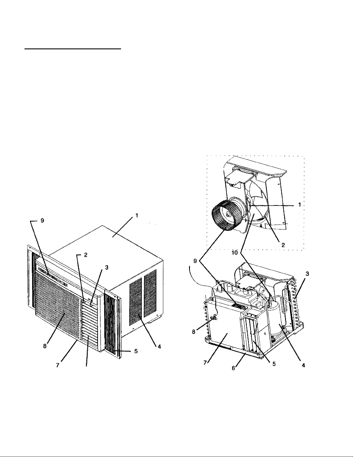
Figures 1 and 2 show location of air conditioner parts
and features described in this manual.
Figure 1 . Air Conditioner External Parts Identification
1. Outer case
2. Air discharge vent airflow direction control lever
3. Vent door control lever
4. Side air louvers
5. Curtain assembly
6. Air discharge vent
7. Front grille
8. Air return vent
9. Electronic control panel
Figure 2. Air Conditioner Internal Parts Identification
1. Fan motor
2. Slinger ring
3. Condenser coil and fins
4. Compressor
5. Vertical air discharge vent louvers
6. Identification plate
7. Evaporator coil and fins
8. Thermostat
9. Blower fan
10. Condenser fan
NOTE: In Figure 2, fan assembly (including blower fan,
condenser fan, fan motor, and slinger ring) is
shown removed for easier component
identification.
Page 5
Sizing Instructions
Many complaints about room air conditioners result
from units that are over-sized or under-sized for a given
area. Over-sized units cool an area before humidity can
be adequately removed, so air feels cold and clammy.
Under-sized units do not sufficiently cool an area.
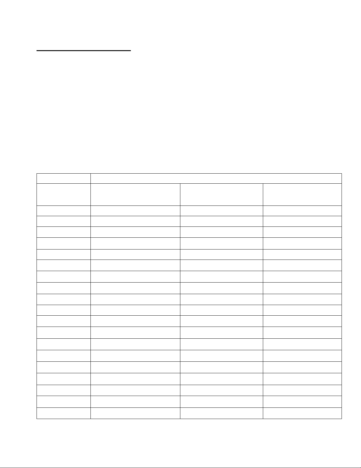
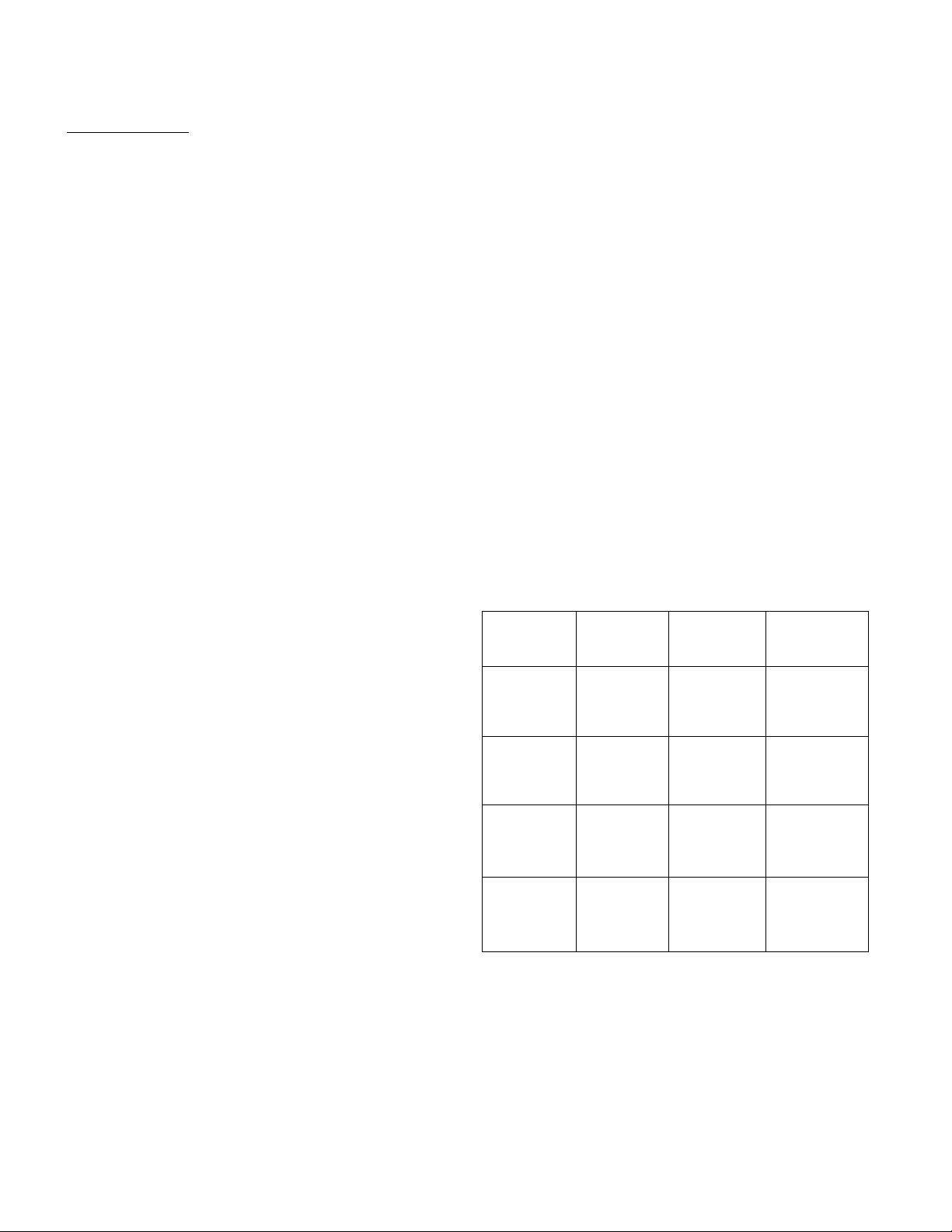
The following table contains guidelines for properly
sizing a room air conditioner for a given area.
To size unit;
1. Determine size (in square feet) of area to be cooled;
locate square footage In far left column of table
below.
Required Air Conditioner Cooiing Capacity—Btu/hour
Size of Area
to be Cooled
(in square feet)
100
150 4000 to 5000
Room below
attic; insulated 4^
ceiling above □□
3500 to 4000
2. Choose right-hand column showing location of room
in building:
• Room below attic; insulated ceiling above.
• Room with occupied room above.
■ Top floor under insulated roof.
3. Follow down right-hand column, reading horizontally
from square footage to find approximate air
conditioner capacity (in Btus per hour) required to
adequately cool designated area.
NOTE: When determining size of unit, also consider
conditions at bottom of table. For best results,
choose air conditioner with cooling capacity
(Btus per hour) closest to, but not exceeding,
estimated size.
Room with /\
occupied
room above EJ
4000 to 4500
4500 to 5000
Top floor under j ■
insulated roof
(no attic) Li—1
4500 to 5000
5500 to 6500
200
250
300
350 6500 to 7500
400 7000 to 8000
450 7500 to 8500
500 8000 to 9000
600
700 10500 to 11500
800
900 12500 to 14000
1000
1200
1400 18000 to 20000
1600 20000 to 22000
1800
4500 to 5500
5000 to 6000
6000 to 7000
9500 to 10500 11000 to 12000
11500 to 13000
13500 to 15000
16000 to 17500 18000 to 20000 26500 to 28500
22000 to 24000
5000 to 6000
5500 to 6500
6500 to 7500
7000 to 8000 10000 to 11000
8000 to 9000
8500 to 9500
9500 to 10500
12000 to 13000
13500 to 14500
14500 to 16000
15500 to 17000
21000 to 23000
23000 to 25000
25500 to 27500
6000 to 7000
7500 to 8500
8500 to 9500
11000 to 12000
11500 to 12500
13000 to 14000
15000 to 16000
17000 to 18000
19000 to 20000
21000 to 22000
23000 to 24500
30500 to 32500
2000
Additional conditions:
• If normal occupancy of area is more than two people, add 600 Btu/hour per person. If normal occupancy is one
person, subtract 600 Btu/hour.
• Add 1200 Btu/hour if area includes a kitchen.
• If room is heavily shaded, subtract 10 percent from total capacity. Increase by 10 percent if area is very sunny.
24000 to 26000
28000 to 30000
Page 6
Installation
installing Room Air Conditioners
Proper installation of a room air conditioner helps
ensure trouble-free operation. Improper installation can
result in problems ranging from excessive noise to
property or equipment damage.
Installation requires some mechanical experience and
aptitude. Depending upon installer’s knowledge and
skill, installation of a room air conditioner can take
between 1 and 3 hours. Professional installation,
performed by authorized Sears technicians, is available.
Contact a local Sears store or call 1-800-4-MY-HOME to
obtain an estimate and schedule an installation.
Before Beginning Any Installation
• Carefully read all installation instructions. Make sure
each step or procedure is understood and any special
considerations are taken into account.
• Before starting installation, assemble all tools,
hardware, and supplies needed. Some items may
need to be purchased locally.
• After deciding where to install unit, carefully examine
location—both inside and outside. Note any potential
obstacles or problems. Choose a more suitable
location, if necessary.
Electrical Requirements
Grounding Instructions
For safety, air conditioner must be grounded. All air
conditioners have power supply cord with three-prong
grounding plug. To minimize possible electrical shock
hazard, power cord must only be plugged into matching
grounding wall receptacle in accordance with National
Electrical Code (and any applicable local codes and
ordinances). If appropriate grounding-type wall
receptacle Is not available, have properly grounded wall
receptacle installed by qualified electrician.
If codes permit and separate grounding wire is used,
have qualified electrician determine if grounding path is
adequate and uninterrupted by plastic, non-metallic
gaskets, or other insulating (non-conductive) materials.
Electrical Connection
A separate (dedicated) circuit is required for units
labeled “Use on Single Outlet Circuit Only.” Devices
covered in this manual require a 60Hz supply. Refer to
unit nameplate for exact voltage requirements. Voltage
requirements can also be determined by type of plug on
ai r cond itioner. See Table 1.
Tablet. Air Conditioner Power Requirements
Unit Plug Receptacle
Type Required
NEMA No. 5-15P
NEMA No. 5-15R 125V-15AMP 115V
Circuit Rating,
Breaker, Time
Delay Fuse
Voltage
Rating On
Nameplate
A WARNING
To avoid risk of personal injury or death due to
electrical shock:
• DO NOT remove warning tag from power cord.
• Electrical grounding is required on all air
conditioners.
• Check with a qualified electrician if you are not
sure intended electrical outlet is properly
grounded.
- DO NOT ground to gas line.
- DO NOT ground to cold water pipe if pipe is
interrupted by plastic, non-metallic gaskets, or
other insulating (non-conducting) materials.
• DO NOT modify plug on power cord. If plug does
not fit electrical outlet, have a matching outlet
installed by a qualified electrician.
■ DO NOT have a fuse in the neutral or ground
circuit. A fuse in the neutral or ground circuit
could result in an electrical shock.
- DO NOT use an extension cord with this device.
• DO NOT use an adapter plug with this device.
• Observe all local codes and ordinances.
©
NEMA No. 6-1SP
(S)
NEMA No. 6-15R
250V-15AMP
23(V208V rated
at 12 amperes or
less
o
NEMA No. 6-20P
NEMA No. 6-30P NEMA No. 6-30R 250V-30AMP
( * )
Do not use an extension cord. If air conditioner power
supply cord does not reach intended wall receptacle,
have qualified electrician install or move appropriate
receptacle closer to unit.
Do not use an adapter plug. If intended wall receptacle
does not match plug on air conditioner, have qualified
electrician replace receptacle with correct type.
NEMA No. 6-aOR 250V-20AMP
f
23<V2oeVraled
over 12 amperes.
but not mora than
16 amperes
206V rated over
16 amperes, but
not more than
24 amperes
Page 7
Installation
Receptacle Wiring
Receptacle wiring must be of adequate size for unit.
Refer to unit identification plate for exact power
requirements. Power requirements can also be
determined by the type of plug on unit. See Table 1 on
preceding page. Minimum size of wiring, based on
power requirements, is:
Units up to 20 amps: 12 gauge
20-30 amp units; 10 gauge
Use copper wire only. It is owner’s responsibility to
provide proper and adequate receptacle wiring that
conforms to alt applicable codes. All wiring should be
installed by a qualified electrician.
Window installation—^7000 and 9000 Btu Units (Models 78079,70089)
______________
CAUTION
To avoid risk of personal injury, property damage, or
product damage due to weight of device and sharp
edges that may be exposed:
■ Air conditioners covered in this manual pose an
excessive weight hazard. Two or more people are
needed to move and install unit. To prevent injury
or strain, use proper lifting and carrying methods.
■ Carefully inspect location where air conditioner
will be installed. Be sure it will support weight of
unit for extended period of time.
• Handle air conditioner with care. Wear protective
gloves whenever lifting or carrying unit. AVOID
sharp metal fins on front and rear coils.
■ Make sure air conditioner does not fall during
installation.
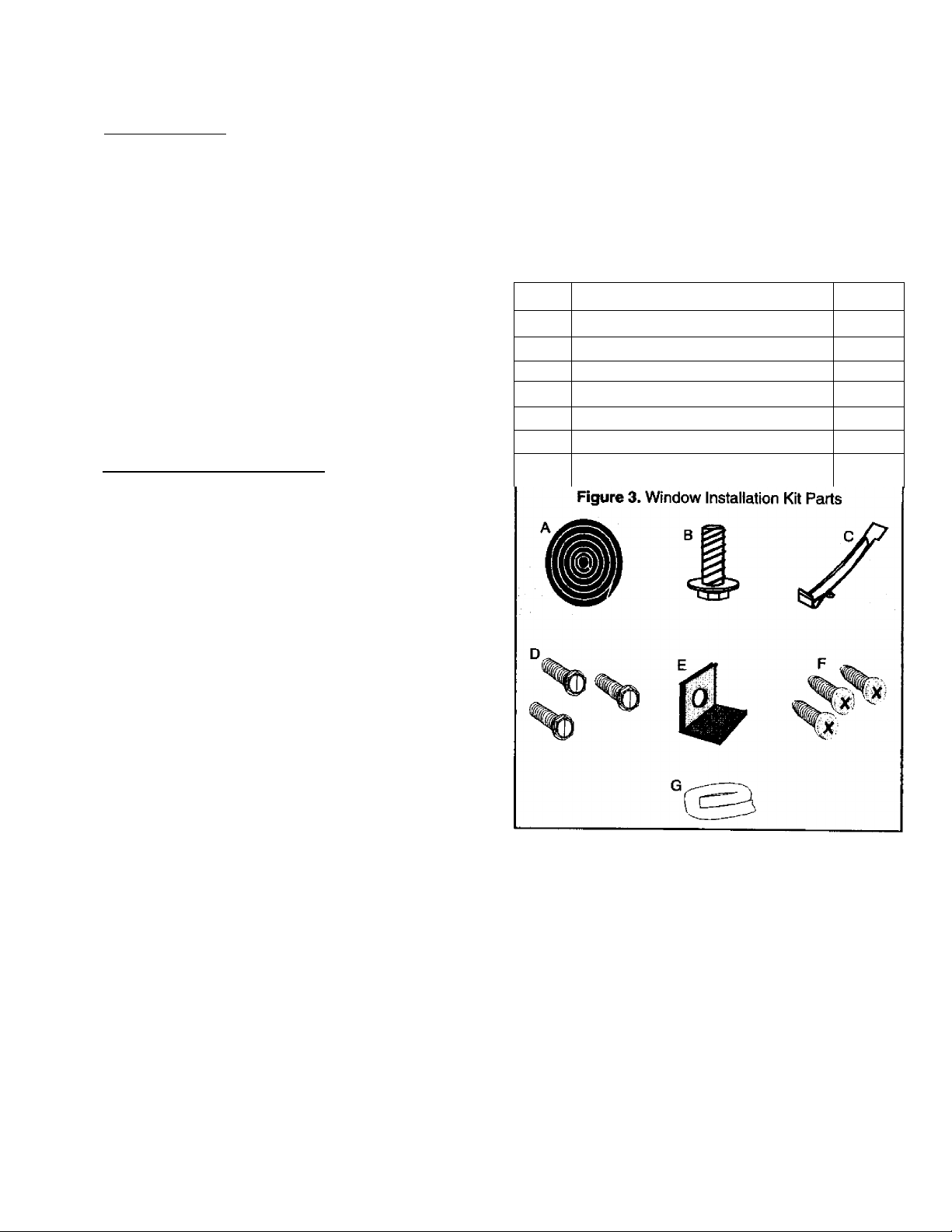
Installation Kit Parts
Window installation kit contains the following parts. Be
sure all parts are included before starting installation. If
parts are missing, contact Sears.
NOTE: Parts are listed in the order used and are
Item#
A
B
C
D
E
F
G
Window sill gasket (W x 14“)
Window seal strip (%" x ^W)
Description
1 adjusting foot
Support bracket
Vb“ hex-head screw
Sash bracket
®/b" Phillips screw
Quantity
40“
1
1
3
1
3
40“
Required Tools and Equipment
• Tight-fitting gloves
• Standard screwdriver
• Phillips screwdriver
• Pliers
• Sharp knife
• Carpenters’level
• ®/e" open-end wrench or adjustable wrench
• 1^" hex socket and ratchet
• Tape measure
• Electric drill
• Va" drill bit
Page 8
Installation
Installation Requirements
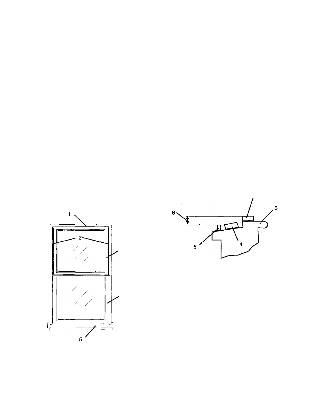
See Figure 4. Inspect window track, sash, and sill.
Ensure window will bear weight of air conditioner for
extended period of time. Measure width of window
opening to be sure air conditioner wiil fit. Air conditioner
is designed for windows 22W to 40" wide. Ensure lower
left inside corner of window is within 6' of an appropriate
electrical outlet,
NOTE: Installation kit is designed for most double-hung
windows that do not have storm windows
installed. If storm window is installed, or if
installation is in a mobile home, window sill may
need modification. See procedure for Storm
Window Modification or for Mobile Home
Window Modification.
Figure 4. Typical Double-Hung Window
1. Window frame
2. Window track
3. Outdoor sash
4. Indoor sash
5. Window sill (indoor)
Next, center 6“ x 4t4" wood block on outside of window
sill between sides of window frame. Wood block must be
same thickness as wood strip installed on indoor sill.
Attach block to outside sill using 3 countersunk screws.
Mounting kit can now be installed.
Figure 5. Window Frame Modification
1. Indoor sash (shown open)
2. Wood strip (1^" wide)
3. Indoor sill
4. Woodblock
5. Storm window frame
6. At least 1" clearance between top of window sill and
top of storm window frame
7. Outdoor sash
’HI
Storm Window Modification
See Figure 5. If storm window frame does not allow
adequate clearance (1" required), remove frame or
create clearance by adding wood strip at least 1W wide
and 1" thick along entire width of sill. Fasten wood strip
to sill with three countersunk wood screws (not
provided) to ensure smooth surface for mounting kit.
Mobile Home Window Modification
See Figure 6. Mobile home window modification
requires adding wood strip at least 1W wide along entire
width of window sill. Thickness of wood strip should
match height of front lip of window frame. Fasten wood
strip to sill with 3 countersunk wood screws (not
provided) to ensure smooth surface for mounting kit.
Mounting kit can now be installed.
Page 9
Installation
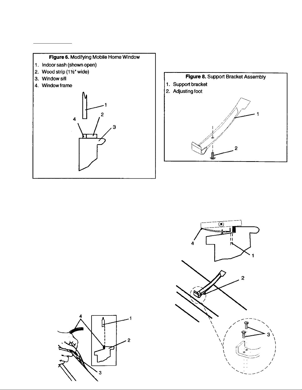
2. See Figure 8. Thread adjusting foot (Item B) through
bottom of support bracket (Item C). Measure width
of window and mark center point of outside silt.
3. See Figure 9. Center support bracket on outside sill,
from rear edge of indoor sill. Secure bracket to
outdoor sill with 2 hex-head screws (Item D).
Installation Procedure
1. See Figure 7. Raise indoor sash and measure sash
width, including portion in window track. Cut window
sill gasket (Installation Kit Item A) to length of indoor
sash and apply to rear of indoor window sill. To
apply gasket, peel back about 2" of paper covering
gasket adhesive, and carefully press exposed
adhesive to one end of window sill. Slowly peel away
remaining paper cover from gasket adhesive, and
press gasket to sill as paper is pulled away.
If window has been modified for installed storm
window, apply gasket to wood strip added to sill.
For mobile home installation, apply gasket to
outdoor side of window frame txittom lip.
Figure 7. Applying Window Sill Gasket
1. Indoor sash
2. Indoor sill
3. Paper covering gasket adhesive
4. Gasket
Figure 9. Installing Support Bracket
1. 1^/ie"gap
2. Center of window
3. Hex-head screws
4. Bubble level
Page 10
Installation
4. See Figure 9. Place bubble level between indoor silt
and outdoor end of support bracket. Turn adjusting
foot on support until level tilts Va bubble toward
outdoor side.
NOTE: Adjusting support bracket for 14 bubble outdoor
slope should result in V*“ backward slope on
installed air conditioner, required for proper water
(condensate) drainage.
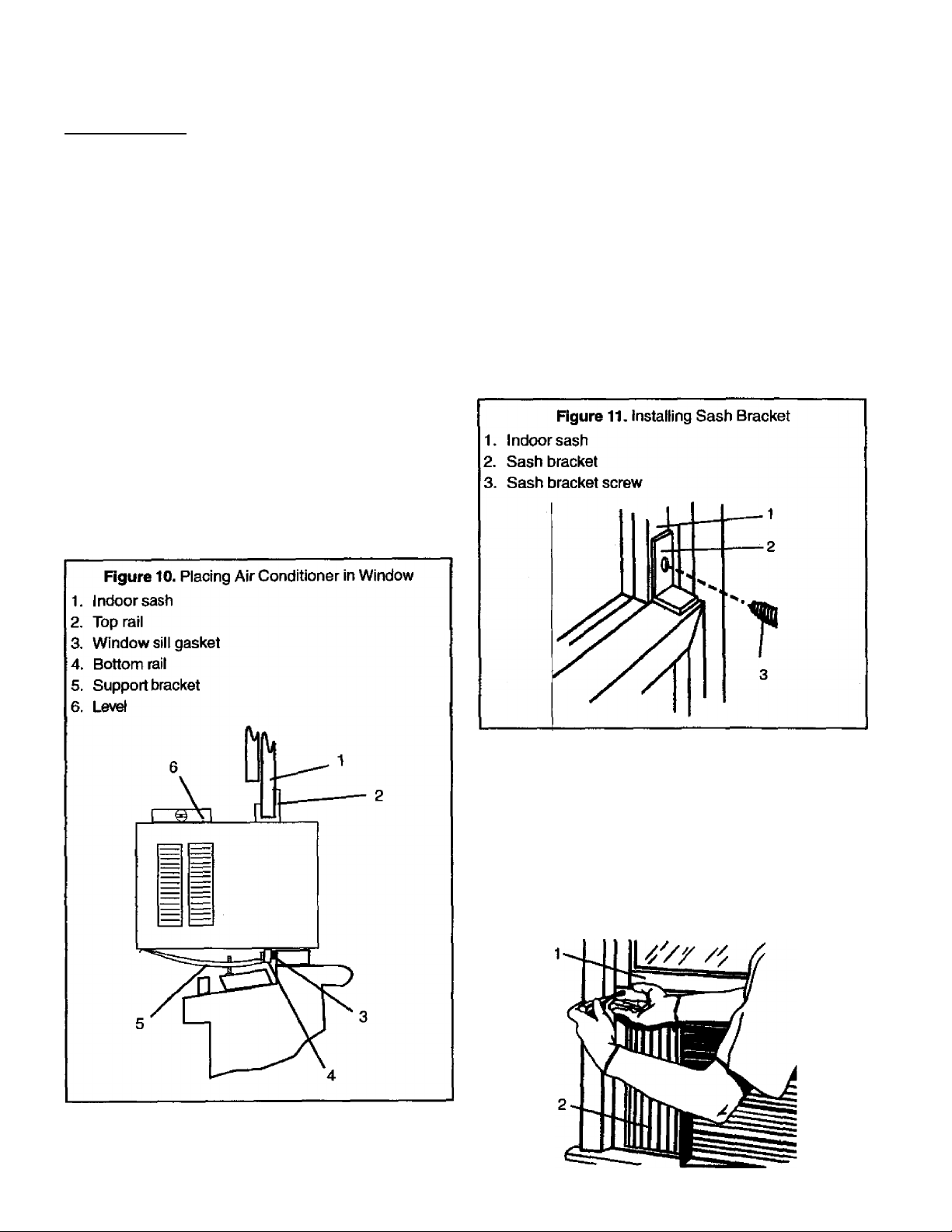
5. See Figure 10. Place air conditioner in window,
centered over support bracket, with bottom raii on
case seated in gap between support bracket and
rear of indoor sill. Lower indoor sash to fit into air
conditioner top rail.
A CAUTION
To avoid risk of personal injury, property damage, or
damage to air conditioner if unit falls, hold air condi
tioner securely in place until indoor window sash is
securely seated in lop rail on outer case.
7. See Figure 11. Position sash bracket (Item E) on top
of indoor sash, flush with outdoor sash. Secure
bracket to outside sash using hex-head screw
(Item D), Drill Ve" pilot hole to make screw easier to
install.
A CAUTION
To prevent damage to window locking or lifting
mechanisms from improperly placed sash bracket
screw, inspect window carefully before drilling or
installing screw in sash.
6. Use carpenters’ level and ensure installed air
conditioner slopes approximately toward outdoor
side. If necessary, remove unit from window and
turn adjusting foot to obtain proper slope.
8. See figure 12. Expand right side curtain on air
conditioner until curtain is tight against window
frame. With curtain tight against frame, find top hole
and mark location on indoor sash. Drill Va” pilot hole
into window sash, and secure curtain to sash using
Phillips screw (Item F). Repeat for left side curtain.
Figure 12. Securing Side Curtain
1. Indoor sash
2. Side curtain
Page 11
Installation
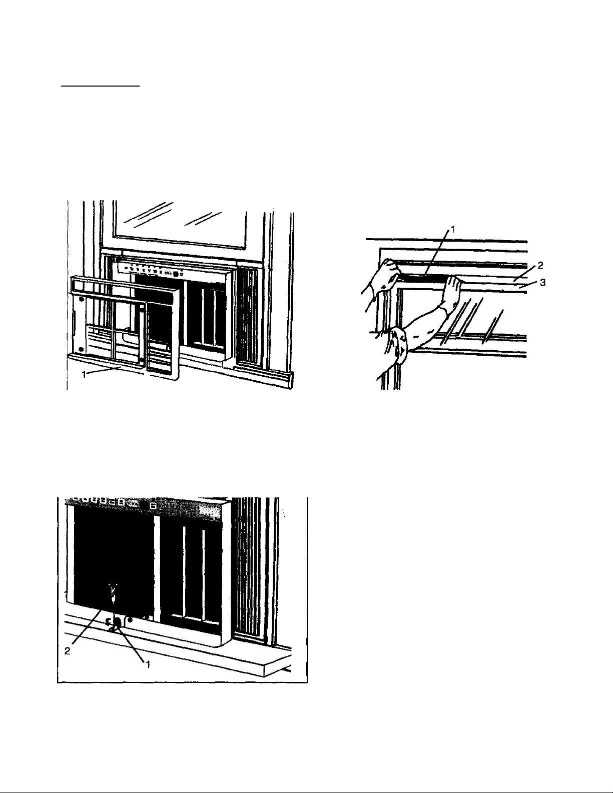
9. See Figure 13. Slide front grille to left; pull out to
remove. Slide air filter to left; pull out to remove.
Remove 4 screws securing front frame to chassis;
pull out on front frame to remove.
Figure 13. Removing Front Frame
1. Front frame
12. See Figure 15. Measure and cut window seal strip
(Item G) to width of window. Stuff window seal strip
between outdoor glass and top of indoor sash for
tight seal to keep out heat and insects.
Figure 15. Installing Seal Strip
1. Window seal strip
2. Outdoor sash
3. Indoorsash
10. See Figure 14. On front rail, bend tab with hole
down toward window sill. Secure tab to sill with Va"
Phillips screw (Item F).
Figure 14. Installing Bottom Rail Screw
1. Front rail tab
2. Bottom rail screw
11. Replace front frame, filter, and grille.
13. To be sure air conditioner installation is correct,
review all steps and ensure all parts are securely
fastened, as outlined in instructions. If final
inspection shows installation is solid and complete,
air conditioner can be operated safely.
To begin operation, plug unit into electrical outlet.
Page 12
Installation
Window Installation—12000, and 18000 Btu
Units
Models 70129,78189)
___________________
A CAUTION
To avoid risk of personal injury, property damage, or
product damage due to weight of device and sharp
edges that may be exposed:
• Air conditioners covered in this manual pose an
excessive weight hazard. Two or more people are
needed to move and install unit. To prevent injury
or strain, use proper lifting and carrying methods.
• Carefully inspect location where air conditioner
will be installed. Be sure it will support weight of
unit for extended period of time.
- Handle air conditioner with care. Wear protective
gloves whenever lifting or carrying unit. AVOID
sharp metal fins on front and rear coils.
- Make sure air conditioner does not fall during
installation.
Required Tools and Equipment
• Tight-fitting gloves
• Standard screwdriver
• Phillips screwdriver
• Pliers
• Sharp knife
• Carpenters’level
• W open-end wrench or adjustable wrench
• hex socket and ratchet
• Tape measure
• Electric drill
• Vs" drill bit
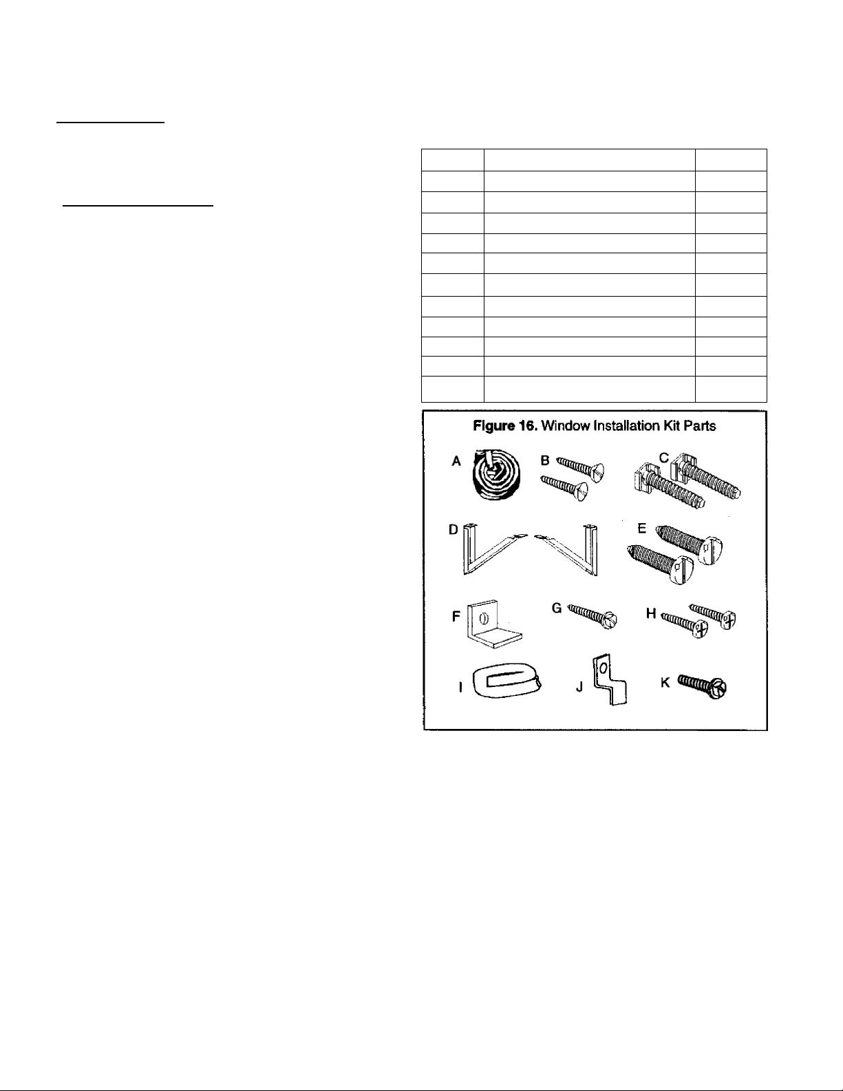
Installation Kit Parts
Window installation kits contain the following parts. Be
sure all parts are included before starting installation. If
parts are missing, contact Sears.
NOTE: Parts are listed in the order used and are
illustrated in Figure 16.
Item #
A Window sill gasket {W x 14") 44"
B Vb" countersunk wood screw
C 4" adjusting foot 2
D Outside support
E yz" screw
F
G 7e" sash bracket screw 1
H ®/b" Phillips screw
I
J Basepan Clip
K
Window seal strip (%" x 1W)
Description
Sash bracket 1
14" screw 1
Quantity
2
2
2
2
48“
1
Page 13
Installation
Installation Requirements
See Figure 17. Inspect window track, sash, and sill.
Ensure window will bear weight of air conditioner for
extended period of time. Measure width of window
opening to be sure installation kit will fit. Air conditioner
is designed for windows 28“ to 42“ wide. Ensure lower
left inside corner of window is within 6‘ of appropriate
electrical outlet.
NOTE: Installation kit is designed for most double-hung
windows that do not have storm windows
installed. If stoim window is installed or if
installation is in mobile home, window sill may
need modification. See procedure for Storm
Window Modification or for Mobile Home
Window Modification.
Figure 17. Typical Double-Hung Window
1. Window frame
2. Window track
3. Outdoor sash
4. Indoor sash
5. Windowsill (indoor)
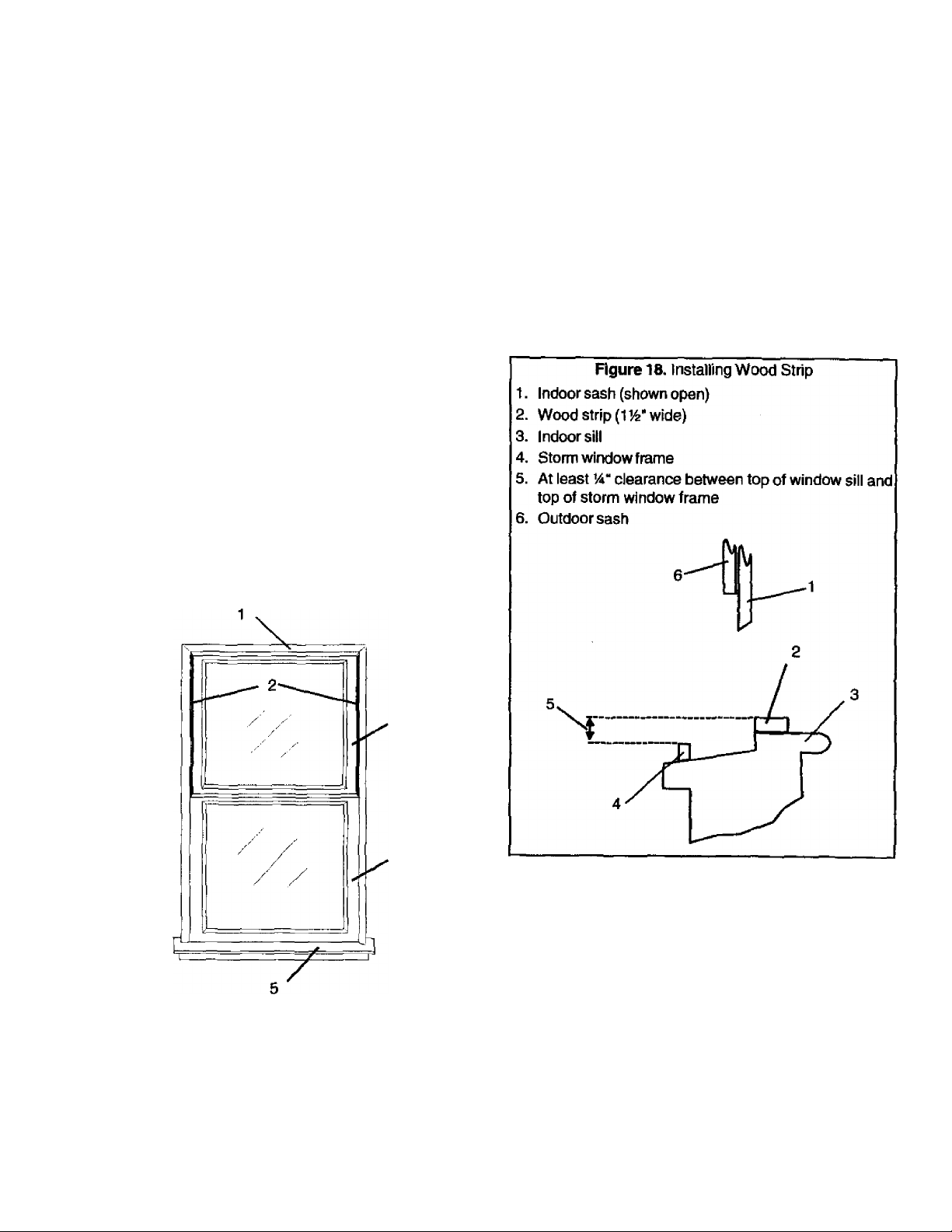
Storm Window Modification
See Figure 18. If storm window frame does not allow
adequate clearance (V4" required) to window sill, remove
frame or create clearance by adding wood strip at 1
wide along entire width of sill. Fasten wood strip to sill
with 3 countersunk wood screws (not provided). Use
countersunk screws to ensure a smooth surface for
mounting kit.
Mounting kit can now be installed.
Page 14
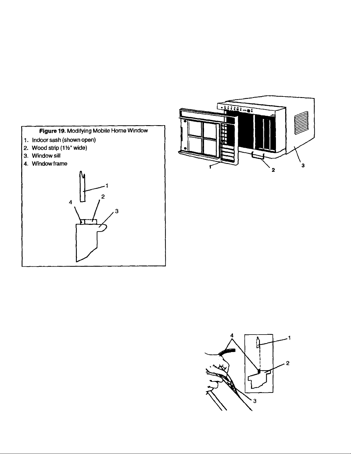
Installatoti
Mobile Home Window Modification
See Figure 19. Mobile home window modification requires
adding wood strip at least 1wide along entire width of
window sill. Thickness of wood strip should match height
of front lip on window frame. Fasten wood strip to sill with
3 countersunk wood screws {not provided) to ensure a
smooth surface for mounting kit.
Mounting kit can now be installed.
Installation Procedure
1. See Figure 20. Slide front grille to left; pull out to
remove. Slide air filter to left: pull out to remove.
Remove 4 screws securing front frame to chassis:
pull out on front frame to remove. Using base pan
handle, remove chassis from outer case. Set
chassis aside.
NOTE: Pull chassis from case slowly and evenly. When
chassis has been pulled out 9” to 12", have two
people (one on either side of case) grasp base pan
and pull chassis completely out of case.
Figure 20. Removing Chassis From Outer case
1. Front frame
2. Base pan handle
3. Chassis
2. See Figure 21. Raise indoor sash and measure
sash width, including portion in window track. Cut
window sill gasket (Installation Kit Item A) to length
of indoor sash and apply to rear of indoor window
sill. To apply gasket, peel back about 2" of paper
covering gasket adhesive, and carefully press
exposed adhesive to one end of window sill. Slowly
peel away remaining paper cover from gasket
adhesive, and press gasket to sill as paper is pulled
away.
If window has been modified for installed storm
window, apply gasket to wood strip added to sill.
For mobile home installation, apply gasket to
outdoor side of window frame bottom lip.
Figure 21. Applying Window Sill Gasket
1. Indoor sash
2. Indoor sill
3. Paper covering gasket adhesive
4. Gasket
3. See Figure 22. Place outer case in window. Lower
indoor sash to fit into top rail on case. Bottom rail on
case must sit behind window sill and against
window sill gasket.
Page 15
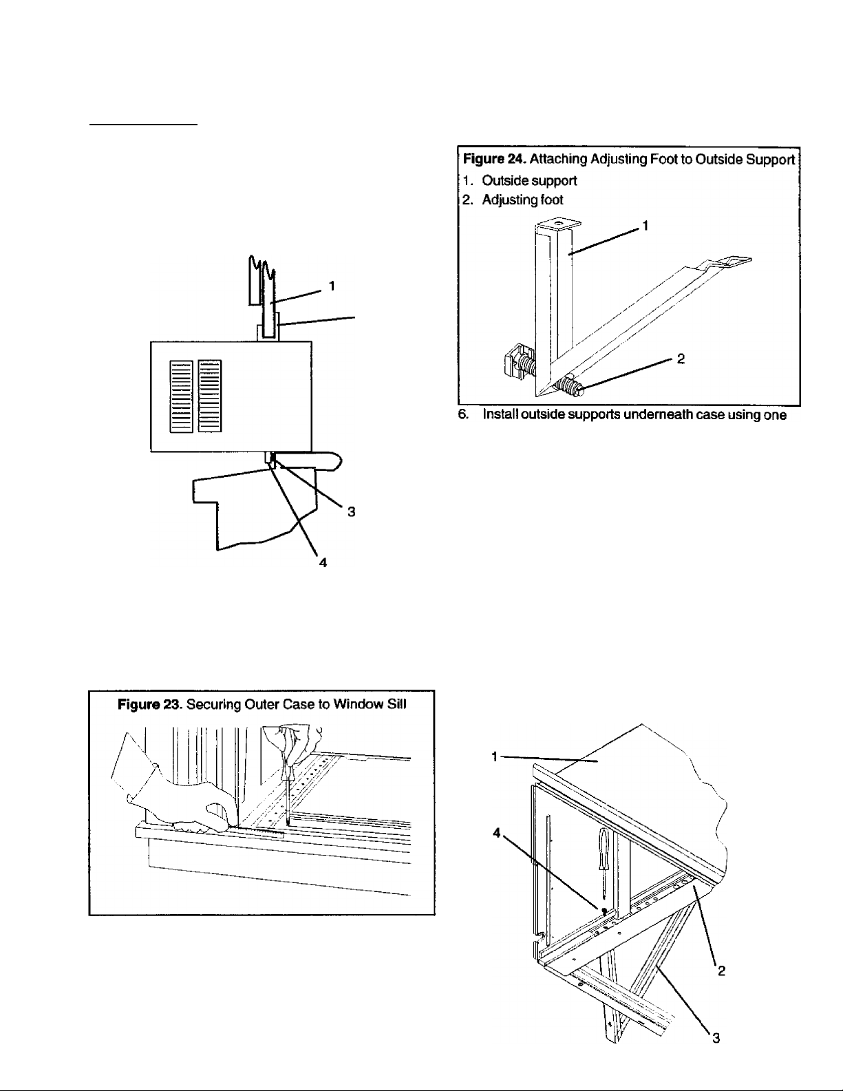
Installation
Figure 22. Installing Outer Case in Window
1. Indoor sash
2. Top rail
3. Window sill gasket
4. Bottom rail
1^" screw (Item E) for each support. Mount vertical
arms (tab with hole) as close as possible to sill.
When properly positioned, adjusting foot faces
house.
7. See Figure 25. Insert tabs on angled support arms
into nearest large holes along bottom of outer case,
one side at a time. Align hole in vertical support arm
tabs with small holes in bottom of case and drive
screws (Item E) into front tabs.
4. See Figure 23. Secure case to window sill by
screwing two 7e" countersunk screws (Item B) into
sill through holes located in front support rail.
NOTE: Drill Va" pilot holes in window sill to make screws
easier to drive.
5. See Figure 24. Screw one Л' adjusting foot into
each outside support (Item D) as far as it will go.
(Adjustments can be made more easily after unit is
in place.) Do not attempt to straighten outside
supports or structural integrity of support may be
compromised.
Rgure 25. Attaching Outside Supports to Outer Case
1. Outer case
2. Insert back support arm tab in large hole
3. Support bracket
4. Attach front support arm with screw through small
hole
Page 16
Installation
A CAUTION
To avoid damage to outside wall of house, especially
if wall is weak or outside supports sit between studs
in wall, place wood blocks (not provided) between
wall and each adjusting foot.
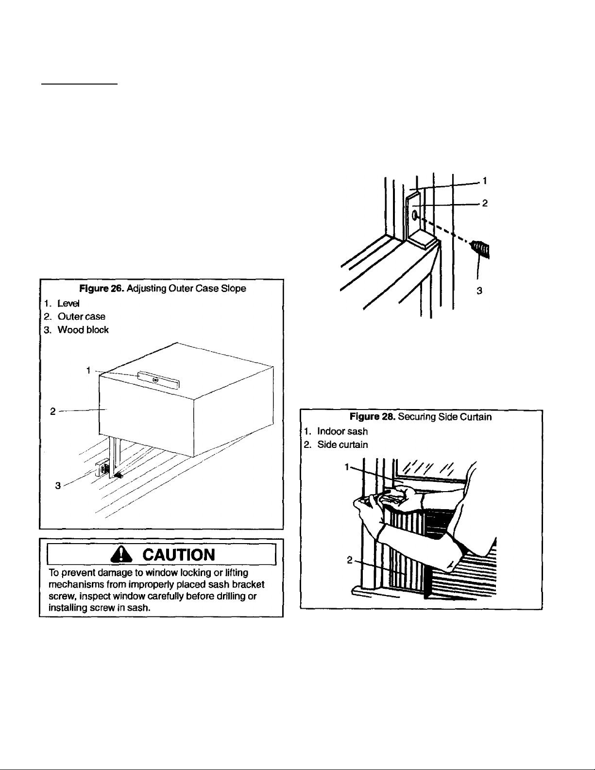
8. See Figure 26. Place carpenters’ level on outer
case. Rear of case should be 14“ to %" lower than
front of case (about bubble on level). Turn each
adjusting foot on outside supports in or out until It
begins to contact wall. Adjust position to achieve
proper slope for case.
Figure 27. Installing Sash Bracket
1. Indoorsash
2. Sash bracket
3. Sash bracket screw
10. See Figure 28, Expand right side curtain on air
conditioner until curtain is tight against window
frame. With curtain tight against frame, find top hole
on curtain and mark location on indoor sash. Drill
Ve“ pilot hole into window sash, and secure curtain
to sash with Phillips screw (Item H). Repeat for left
side curtain.
9. See Figure 27. Position sash bracket (Item F) on top
of indoor sash, flush with outdoor sash. Secure
bracket to outside sash using Va" sash bracket
screw (Item G). Drill a Ve’ pilot hole so screw is
easier to install.
11. See Figure 29. Measure and cut window seal strip
(Item)) to width of window. Stuff window seal strip
between outdoor glass and top of indoor sash for
tight seal to keep out heat and insects.
Page 17
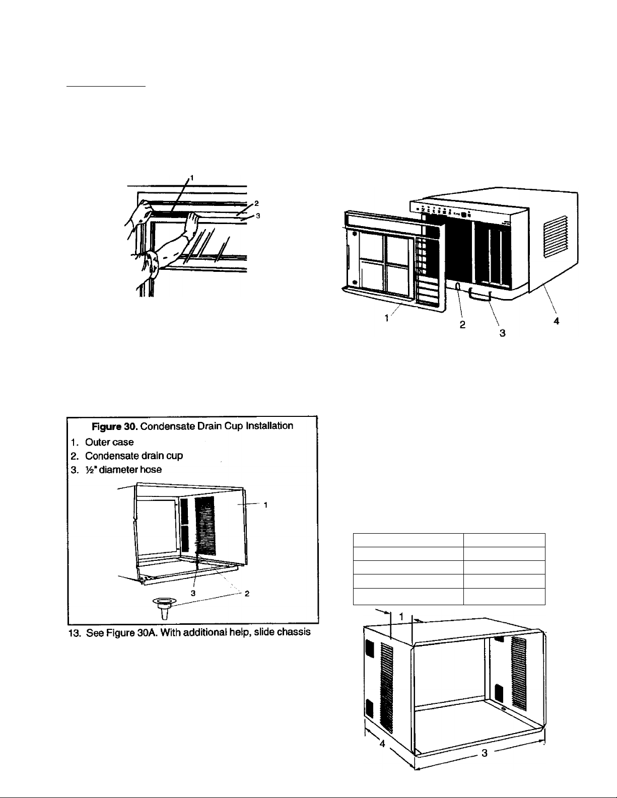
Installation
Figure 29. Installing Seal Strip
1. Seal strip
2. Outdoor sash
3. Indoorsash
12. See Figure 30. Under normal conditions, unit can
evaporate water as fast as it is removed from indoor
air. In very humid conditions, however, excess water
may drip off chassis. To avoid dripping, instail
condensate drain cup (included with unit). Insert
condensate drain cup through Va" hole recessed in
flange on right side of outer case bottom. Then
place Vi" diameter hose or tube on bottom spout of
drain cup.
Figure 30A. Attaching Chassis To Outer Case
1. Front frame
2. Base pan clip
3. Base pan handle
4. Chassis
Through-the-Wall Installation—12000, and
18000 Btu Units (Models 70129, and 78189)
Kenmore Room Air Conditioners with slide-out chassis
cases (models 70129, and 78189) are designed to be
install^ in a window or through a wall. Following are
instructions are for wall installation.
NOTE: Kenmore Room Air Conditioner Models 78079 and
70089 (7000 and 9000 Btu) are designed for
window installation only. See instructions
beginning on page 7.
Typical Cabinet Dimensions
Figure 31. Slide-Out Chassis Outer Case Dimensions
12000 Btu
1. 9 inches
16Vi inches 19Vfe inches
2.
23% inches
3.
23Vi6 inches 28 V^ inches
4.
18000 Btu
14Vfe inches
25% inches
into outer case. Attach base pan retaining clip to
chassis with V4" screw. Reinstall front frame, air
filter, and front grille. Because window sash helps
keep unit in window, make sure sash contacts case
before reinstalling chassis.
14. To be sure air conditioner installation is correct,
review all steps and ensure all parts are securely
fastened, as outlined in instructions. If final
inspection shows installation is solid and complete,
air conditioner can be operated safely.
To begin operation, plug unit into electrical outlet.
Page 18
Installation
General Instructions
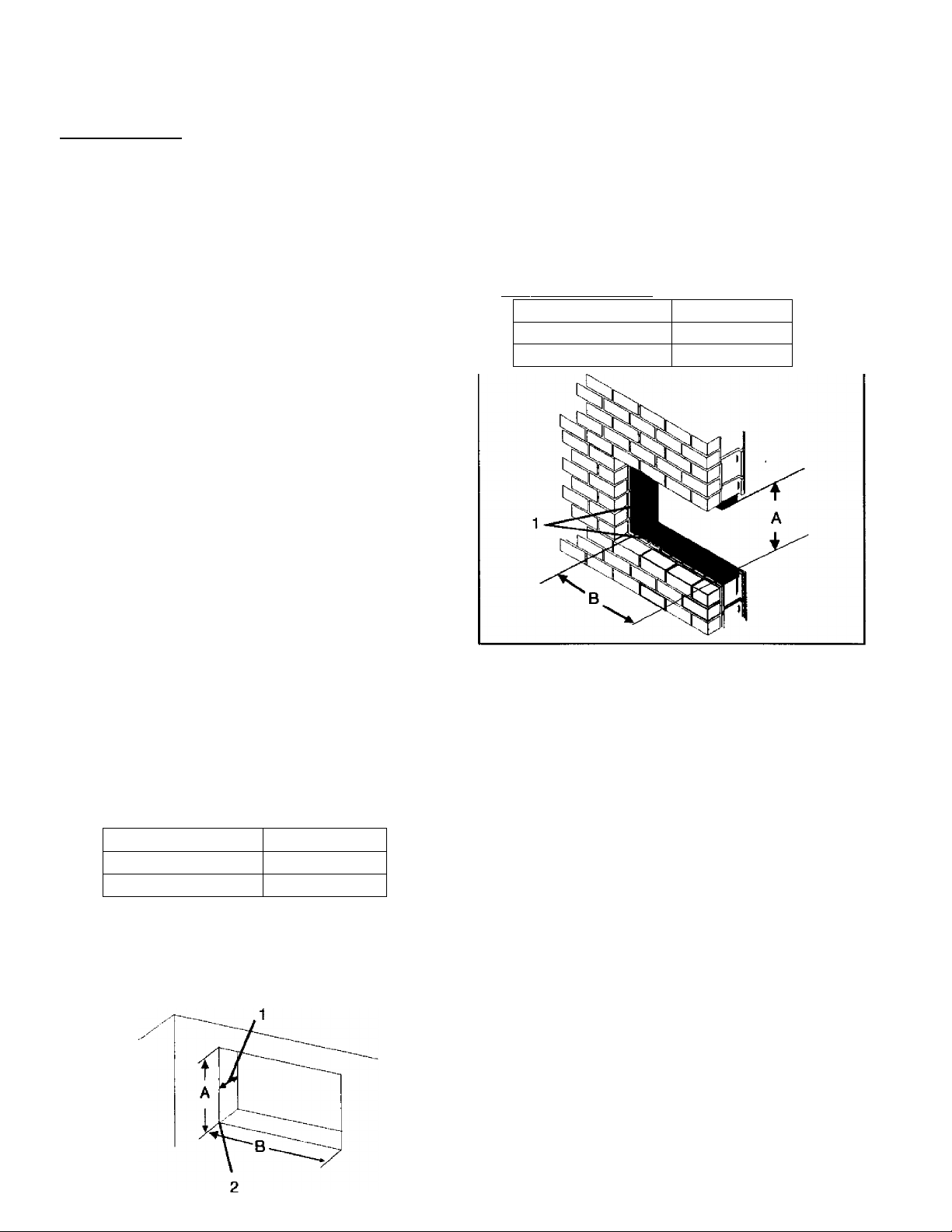
See Figure 32. Dimensions of finished opening (required)
in wali are:
• 24%” wide by 16%" high (12000 Btu model).
• 19%" high by 257s" wide (18000 Btu model)
Lower left inside comer of opening must be within 6' of
appropriate electrical outlet.
For proper condensate drainage when installed, back of
case should be W lower than front of case. Inside edge
of case must extend W beyond inside wall to properly
seat air conditioner front cover. After installation, caulk
completely around outside of unit to ensure proper seal.
Depending upon wall construction and opening location,
a lintel (not provided) may be required.
A CAUTION
To reinstall chassis and reattach front cover, outer
case must be square and level from side to side.
Use wood shims between sides of case and
finished opening—especially where case is secured
to opening—^to prevent warping or distorting case.
Check installation with carpenters' square.
Brick Veneer or Frame Walt Construction
See Figure 33. A framed, finished opening of proper
dimensions should be cut out or built into wall. Frame
opening with 2" x 4" lumber.
Figure 33. Brick Veneer Wall Opening
1. 2* X 4" framing lumber
12000 Btu
A = 16% inches 19% inches
B = 24% inches 257b inches
18000 Btu
To improve appearance, framing inside opening with
decorative molding (not provided) may be desired. If
molding is used, mount case in opening so inside edge
of case extends %" beyond molding.
When installing unit through thick walls (12000 Btu unit
in walls thicker than 9’; 18000 Btu unit in walls thicker
than 14Vè"), be sure air flows freely through side louvers
on outer case. See Installation in Walls Exceeding Outer
Case Dimensions.
Figure 32. Typical Wall Opening
12000 Btu
A = 16% inches
B = 24% inches
1. See Installation in Walls Exceeding Outer Case
Dimensions.
2. Appropriate electrical outlet must be within 6' of this
point.
18000 Blu
19% inches
25Vb inches
To install outer case in opening:
1. See Step 1 under Window Installation—12000, and
18000 Btu Units to remove air conditioner chassis
from outer case.
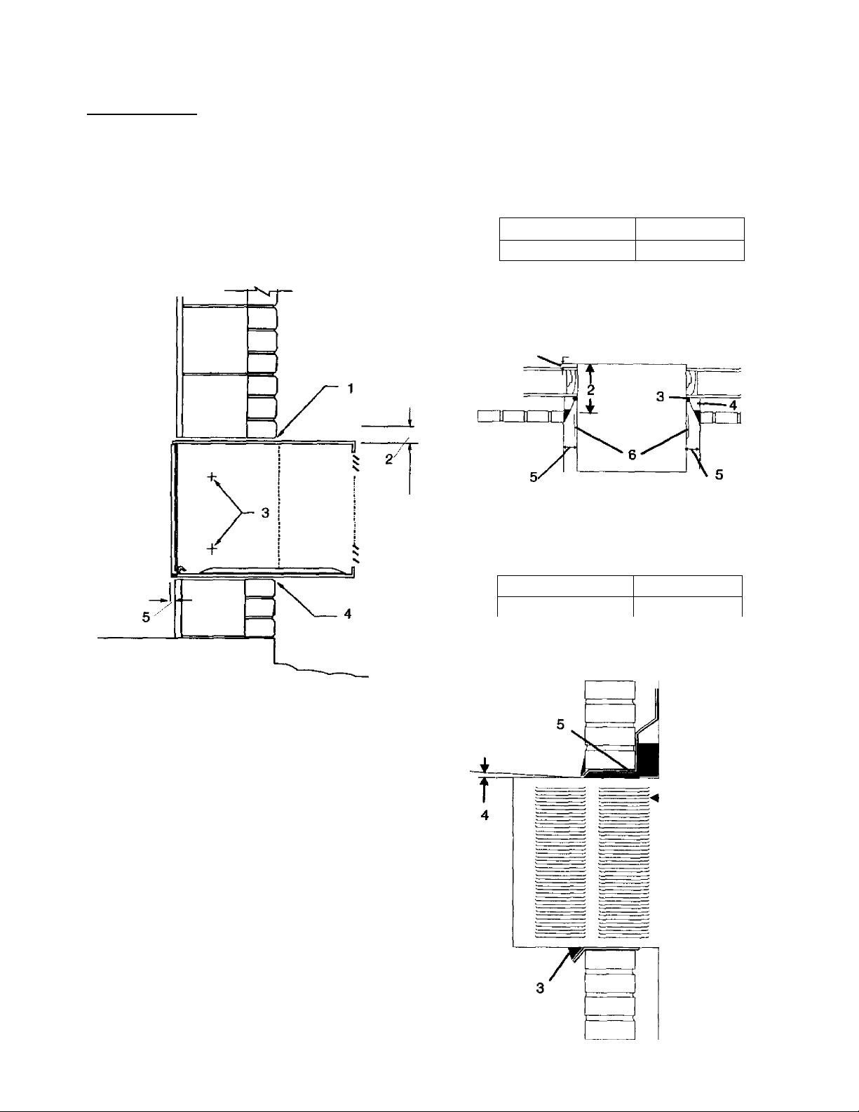
2. See Figure 34. Place outer case in wall opening.
Adjust case so front extends into room %" and case
has a W back slope (lay carpenters’ level inside
case and adjust case to % bubble on level).
NOTE: If air conditioner will be framed by decorative
molding, extend case into room %“ beyond molding.
3. Pre-drill holes in each side of case at approximate
locations shown in Figure 34. Use wood shims to fill
gaps between case and finished opening, especially
where case will be secured to wall. DO NOT WARP
or distort case when installing shims.
When properly positioned, secure case in opening
with four #10x1" (25mm) wood screws (not
provided).
4. Caulk all four sides of case to seat case in place.
Page 19
Installation
Figure 34. Securing Outer Case in Wall Opening
1. Lintel and flashing (if required)
2. Provide W slope to outside for condensate drainage
3. Attach outer case to framing in two places on each
side of case
4. Completely caulk or seal all four sides of outer case
5. Outer case extends into room W
Figure 35. Chamfering Walls That Exceed Outer Case
Dimensions (Top View)
1. Outer case extends into room
2.
12000 Btu
9 inches
3. Caulk around outer case to seat in place
4. Mortar
5. 4" clearance required for unrestricted air flow
6. Side louvers
18000 Btu
141^ inches
1
Figure 36. Chamfering Walls That Exceed Outer Case
Dimensions (Side View)
1. Outer case extends into room
2. Distance from front of outer case to side louvers
12000 Btu
9 inches
3. Caulk around outer case to seal in place
4. Install outer case with W slope to outdoor side
5.
Install lintel and/or flashing, if necessary
18000 Btu
inches
Masonry Construction
See Figure 32 for dimensions of finished opening to cut
out or build into masonry wait. Seal outer case in place
with mortar or secure to wall with concrete nails driven
through sides of case.
NOTH: If securing case with concrete nails, pre-drill
holes in case before driving nails into wall.
Installation in Walls Exceeding Outer Case Dimensions
Air conditioner must be installed so air flows freely
through side louvers to prevent overheating of
compressor and fan motor. If dimensions of wall restrict
airflow to louvers, wall opening must be modified by
chamfering vertical portions of outside opening, as
shown in Figures 35 and 36.
Page 20
Controls
Figure 37. Touch Control Panel
•
• m
SET
LOW
COOL
MED
COOL
MODE
HIGH
COOL
SMARf
(off)
.
. -
power),
'^ll
SET
See Figure 37. Kenmore room air conditioners have an
electronic touch control panel located across top front of
unit. Functions and operation of each control are
explained below.
Touch Panel Controls
To operate touch controls, press control pad until
indicator above pad lights (does not apply to OFF or
VIA P^ds).
OFF—Turns air conditioner off.
SMART SET—Places air conditioner in "smart” cooling
mode. SMART SET uses computer logic to cool area
quickly and quietly. When unit first turns on, fan starts at
high speed. As room temperature nears set
temperature, fan automatically switches to medium
speed, then low speed. When room cools to set
temperature, fan continues to run at tow speed and
compressor cycles on and off to maintain room
temperature.
LOW COOL—Fan operates continuously at low speed,
except in power saver mode. If unit is in a cooling mode,
compressor cycles on and off as required to maintain
set temperature. Select this setting for quietest
operation.
MED COOL—Fan operates continuously at medium
speed, except in power saver mode. If unit is in a
cooling mode, compressor cycles on and off as required
to maintain set temperature. Select this setting for
reduced air circulation and quieter operation.
HIGH COOL—Fan operates continuously at high speed,
except in power saver mode. If unit is in a cooling mode,
compressor cycles on and off as required to maintain
set temperature. Use this setting for maximum air
circulation and faster cool-down during initial start up.
POWER SAVER PLUS—Places air conditioner in
energy-saving mode. Energy-saving mode works in
conjunction with SMART SET mode and low, medium,
or high fan speeds. In energy-saving mode, air
conditioner maintains room temperature within 1.5° F of
programmed temperature setting. When POWER
SAVER PLUS is selected, fan cycles on and off with
compressor, instead of running continuously as in other
modes. During compressor off cycle, fan automatically
turns on for about 2 minutes at 5 minute intenrals to
sample room air temperature. If room temperature is
within 1.5°F of programmed temperature, time between
sampling increases to a maximum of 15 minutes.
m
ÍDELAY)
(sTARTj ■DBBBIBB
EXHAUST CLOSED
It room temperature is more than 1,5°F above
programmed setting, fan continues to run and
compressor cycles on to coot room. When room cools
to set temperature, compressor and fan turn off and
time between air sampling cycles decreases to a
minimum of 5 minutes.
FAN ONLY—Fan operates continuously at set speed
(high, medium, or low) and compressor remains off..
Use this setting to circulate air without cooling and, with
VENT CONTROL in EXHAUST position, to vent room
of stale air, odors, smoke, etc. Displays actual room
temperature.
V I A —decrease (“down” arrow) or increase
(“up" arrow) set temperature. When used with DELAY
START function, arrow keys adjust delay start or stop
time.
DELAY START—^Allows programming a delay of up to
24 hours before air conditioner starts, or programming
air conditioner to automatically stop after up to 24 hours
of operation. Automatic start or stop is programmable
from 1 hour (minimum) up to 24 hours (maximum), in
one hour increments. See Operation Instructions for
information on programming air conditioner for delay
start or automatic stop.
Vent Control
Vent control lever, located on lower right corner of front
panel, controls a damper that recirculates or exhausts
room air.
With control in CLOSED position, damper is closed and
air in area being cooled is recirculated through air
conditioner, filtered, cooled, and returned to room. No air
is exhausted (vented) outside.
NOTE: For maximum efficiency and cooling, vent
control should remain closed any time air
conditioner is cooling.
With control in EXHAUST position, damper is open.
When open, room air is exhausted (vented) outside.
Use exhaust position to remove stale or smoky air.
NOTE: To conserve energy, use FAN ONLY position
with EXHAUST feature.
Brightness Adjust Feature (some models)
Display brightness can be changed using V | A
To decrease brightness, simultaneously press and hold
OFF pad with “down" arrow. To increase brightness,
press and hold OFF pad with “up" arrow key.
Page 21
Operating Instructions
Before Turning Air Conditioner On
To operate air conditioner efficiently and ensure it
provides maximum comfort;
• Tightly close all doors and windows in area being
cooied.
• Keep air flow to or from unit free of obstructions. Do
not place plants, furniture, lamps, etc., in front of air
conditioner return air vent or air discharge vent.
• Keep outdoor louvers free of obstructions. Keep fins
on evaporator and condenser coils free of dirt and
debris.
• Clean air filter regularly.
NOTE: Clean air filter at least once a week during
continuous operation. More frequent cleaning may be
required in extremely dusty environments. NEVER
operate air conditioner with air filter removed.
• Plug power cord into appropriate receptacle only. See
Electrical Requirements on pages 6 and 7.
When area cools to desired temperature, fan speed can
be reduced for quieter operation. Compressor will
periodically cycle on and off to maintain room
temperature at selected level.
Smart Set Mode
To operate air conditioner in Smart Set mode:
1. Press SMART SET pad on control panel. Fan begins
operating at high speed and automatically switches
to medium, then low, speed as room air nears
desired temperature.
NOTE: Compressor lockout feature delays start of
compressor for 3 minutes after unit is plugged in,
or if restarted less than 3 minutes after last
compressor cycle.
2.
Press \/ I pad to set temperature at desired
level of cooling.
After room reaches set temperature, fan continues to
run at low speed and compressor cycles on and off to
Normal Cooling Mode
Air conditioner is in “norma!” cooling mode whenever
LOW COOL, MED COOL, or HIGH COOL pads are
pressed and no other pad is pressed at same time. To
run air conditioner in normal cooling mode:
1. Press HIGH COOL pad on control panel. High fan
speed will cool area to desired temperature quicker
than slower speeds.
NOTE: Compressor lockout feature delays start of
compressor for 3 minutes after unit is plugged in,
or if restarted less than 3 minutes after last
compressor cycle.
2. Press \/ I /\ pad to set temperature at desired
level of cooling.
After room reaches set temperature, fan cycles on and
off with compressor. See POWER SAVER PLUS
description on previous page.
Fan Only Mode (No Cooling)
Use Fan Only mode for venting area of stale or smoky
air, removing odors, or simply circulating air without
cooling. Displays actual room temperature. To operate
air conditioner in Fan Only mode;
1. Open vent door by placing vent control in EXHAUST
position. Opening vent door allows indoor air to be
exhausted outside.
2. Select desired fan speed (low, medium, or high) by
pressing appropriate pad on control panel (LOW
COOL, MED COOL, or HIGH COOL).
3. Press FAN ONLY pad.
Page 22
Operating Instructions
Delay Start Operation
To program delay start:
1. Turn unitoff (press OFF pad).
2. Press DELAY START pad. Display flashes currently
programmed temperature setting.
3. Program new temperature setting (if desired) using
VI Apad-
NOTE: Current temperature setting is used if not
changed within 5 seconds.
4. Select desired operating mode and fan speed.
5. Press DELAY START pad. Display flashes currently
programmed delay time—1 through 24 (hours).
6. Program new delay time (if desired) using \/ |
pad.
NOTE: Current delay time is used if not changed within
5 seconds.
7. Press DELAY START pad to start timer. Display
shows time remaining until unit automatically starts.
At programmed time, unit automatically starts in
programmed operating mode.
NOTE: Timer automatically starts after 5 seconds if
DELAY START pad is not pressed.
To program automatic stop:
1. Start air conditioner in desired operating mode. If
unit is already in desired mode, go to step 2.
Press DELAY START pad. Display flashes currently
2.
programmed time—1 through 24 (hours).
Program new time (if desired) using \/ | ^ pad.
3.
NOTE: Current time is used if not changed within 5
seconds.
4. Press DELAY START pad to start timer. Display
shows time remaining until unit stops. When
programmed time elapses, unit automatically stops.
NOTE: Timer automatically starts after 5 seconds if
DELAY START pad is not pressed.
To cancel delay stop program, press DELAY START pad
after timer starts counting down, or turn unit off (press
OFF pad).
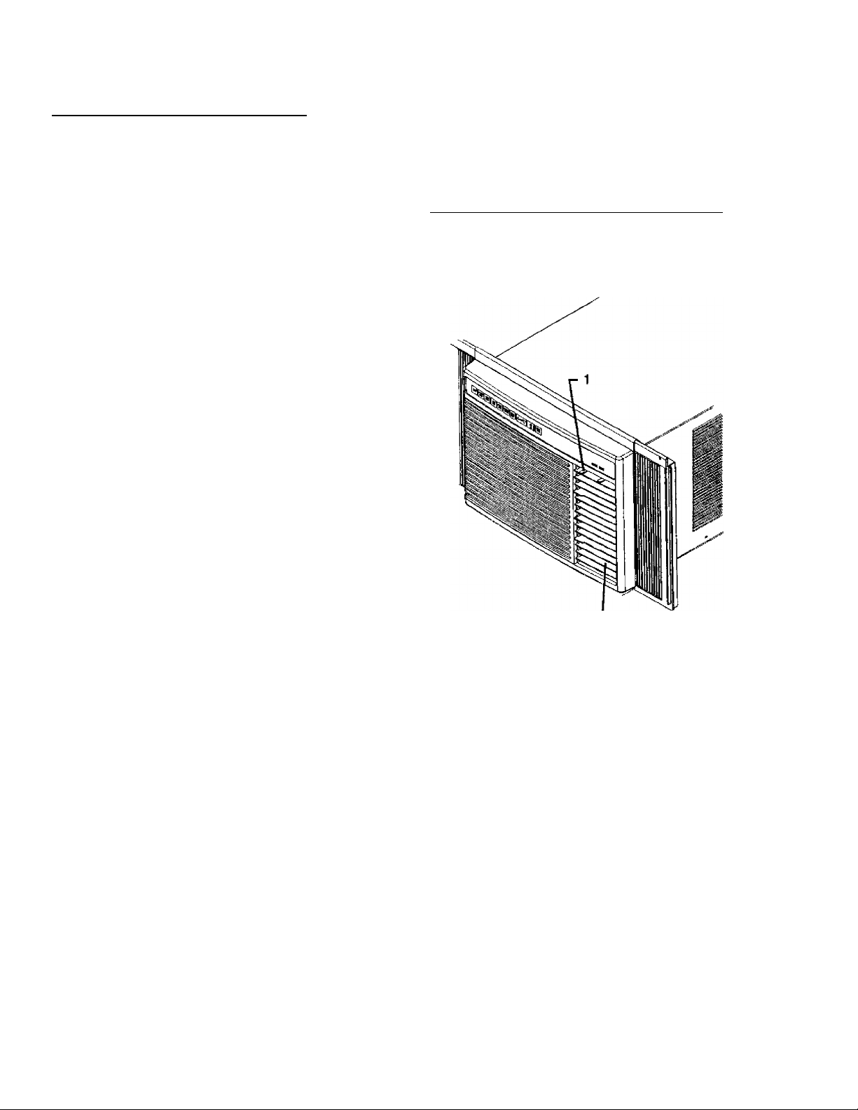
Adjusting Airflow Direction
See Figure 38. Position of air discharge vent louvers
determines direction of airflow from vent. Direction can
36 adjusted upward, downward, left, and right.
______
Figure 38. Airflow from Air Discharge Vent
1. Airflow direction control lever
2. Air discharge vent horizontal louvers
To adjust airflow upward or downward, move horizontal
louvers on outside of air discharge vent up or down.
To adjust airflow left or right, move airflow direction control
lever left or right.
Energy Saving Tips
In addition to operating air conditioner in energy-saving
mode, savings of energy and money can be realized by:
• Increasing insulation in walls and ceilings.
■ Closing all heating and ventilation diffusers or vents
(including furnace cold air return vent) in area being
cooled.
• Closing drapes or blinds on windows that receive
direct sunlight. Install window coverings or awnings
on windows not currently covered.
• Adequately ventilating attic. Heat build-up in attic adds
to air conditioner cooling load.
• Avoiding use of heat-producing appliances during
hottest parts of day.
• Turning off lights and appliances when not needed.
• For maximum efficiency and cooling, vent door should
be closed whenever air conditioner is cooling.
Page 23
Operating Instructions
Normal Operating Sounds
Certain sounds may be made when air conditioner runs,
especially in a cooling mode. Sounds may include:
• Water splashing onto condenser; caused by slinger
ring attached to condenser fan. Slinger ring picks up
water (condensate) in base pan and sprays it on
condenser to increase efficiency of unit.
Care and Maintenance
A WARNING
To avoid death or personal injury due to electrical
shock, turn off fan control and unplug power cord
before cleaning or performing maintenance on this
device.
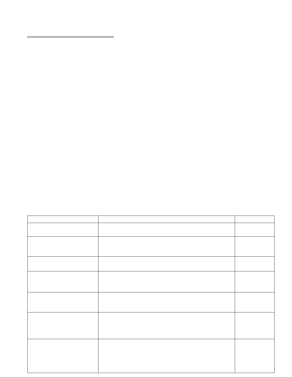
Maintenance Schedule
Kenmore Room Air Conditioners are designed and
manufactured to provide years of dependable service
when properly cared for and maintained.
Compressor cycles frequently. High efficiency
compressors used in new Kenmore Room
AirConditioners run more frequently but for shorter
periods and consume less energy than older, less
efficient compressors.
Airflow from air discharge vent. If sound is distracting,
try adjusting louvers on discharge vent, moving objects
that may be obstructing airflow, or reducing fan speed.
Maintenance Schedule (below) shows maintenance
required to keep unit operating at peak efficiency. Most
maintenance can be performed using common tools,
equipment, and products. See Maintenance Procedures
(beginning on page 24).
Large maintenance tasks, such as washing condenser
and evaporator coils, should performed by an authorized
Sears servicer (at owner’s expense). Call 1 -800-4-88
1222 for location of a local authorized Sears Service
Center.
Maintenance Required
Inspect/clean air filter.
Inspect/clean air discharge
louvers, return air grille, and
electronic control.
Inspect louvers on outer case
for obstructions.
1 nspect condenser coil.
Inspect evaporator coil.
Inspect outer case for
signs of damage.
Inspect/clean base pan.
Table 2. Maintenance Schedule
Procedure
Remove air fitter and inspect. Clean if required; replace.
NOTE: Never operate air conditioner with filter removed.
Inspect air discharge louvers, return air grille, and electronic
control for dust and dirt accumulation. Clean, if necessary.
NOTE: Inspect more often in dusty environments.
inspect louvers on outer case and remove any obstructions.
Inspect condenser coil for dirt, bent fins, and other
obstructions. Clean/repair, if necessary.
NOTE: Inspect more often in dusty environments.
Inspect evaporator coil for dirt, bent fins, and other
obstmctions. Clean/repair, if necessary.
NOTE: Inspect more often in dusty environments.
Inspect interior and exterior of outer case for scratches,
paint blisters, rust, and other damage. Repair as necessary.
NOTE: Inspect more often in salty or other corrosive
environments.
Inspect base pan for scratches, blisters, rust, dents, and other
damage. Repair as necessary. Clean condensate drain
passages of any accumulated material.
NOTE: In areas of excessive humidity, use algicide (algae
inhibitor) in base pan to help reduce algae build-up.
Frequency
Weekly
Weekly
Monthly
Annually
Annually
Annually
Annually
Page 24
Care and Maintenance
Maintenance Procedures
Л WARNING
To avoid death or personal injury due to electrical
shock, turn off fan control and unplug power cord
before cleaning or perfonning maintenance on this
device.
Air Filter Removal and Cleaning
NOTE: Never operate air conditioner with filter
removed.
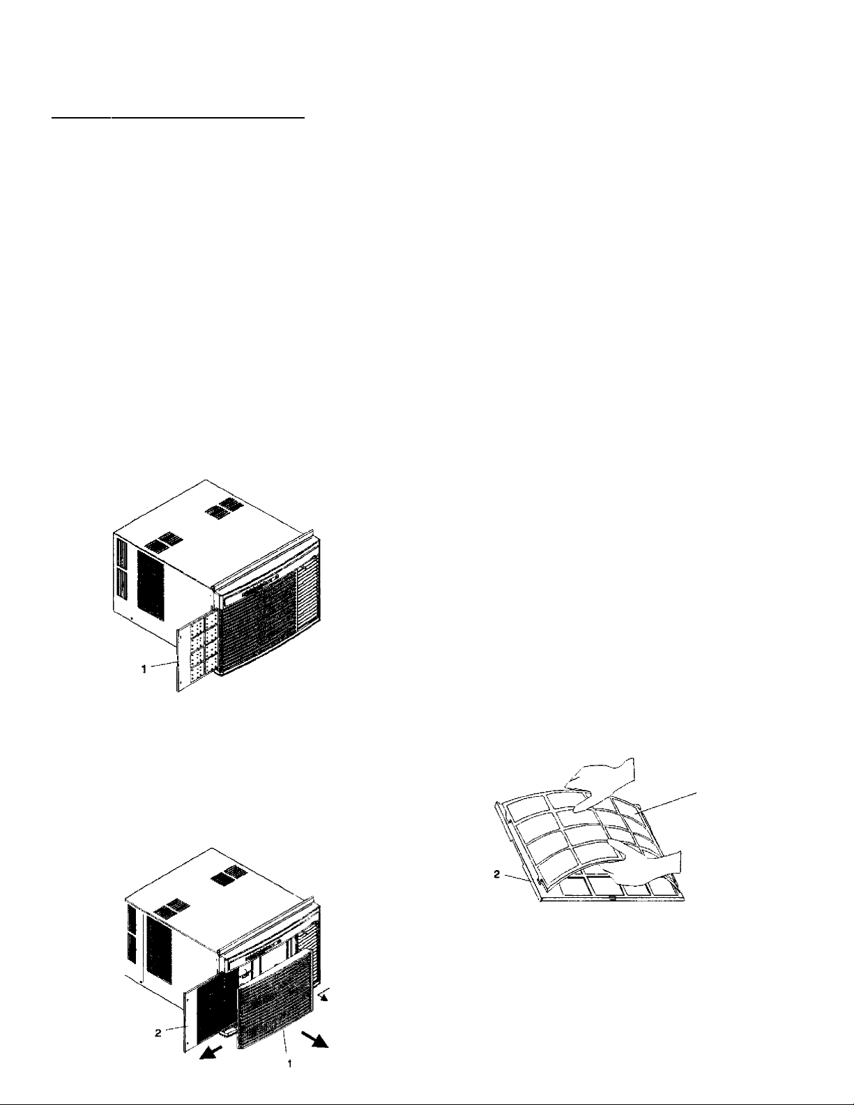
Air filter can be removed in two ways:
• See Figure 39. Grasp filter handle and pull to the left.
When filter clears return air grille, pull out and away
from air conditioner.
Figure 39. Removing Air Filter, Method One
1. Air filter
Clean air filter by vacuuming. If filter is especially dirty,
clean with mild solution of warm soapy water. Rinse filter
of all soap residue and dry completely before
reinstalling.
Air Purification Filter
Optional, disposable air purification filter can be mounted
behind permanent fitter to reduce smoke, odor, pollen,
and dust from area being cooled. After approximately 3
months of use, charcoal-impregnated air purification filter
should be discarded. New air purification filters are
available fmm Sears. Order part number
• 20056001 (7000 and 9000 Btu air conditioners)
• 20064601 (12000 Btu air conditioners)
• 20075401 (18000 Btu air conditioners)
Optional Air Purification Filter instaliation and
Removai
1. Remove permanent air filter from air conditioner.
2. See Figure 41. Insert 3 tabs on right side of air
purification filter into 3 matching slots on back of
permanent air filter frame.
3. Carefully bow center of air purification filter and
insert 2 tabs on left side into matching slots on
permanent filter frame.
4. Relcix bow. Air purification filter should rest against
rear of permanent air filter.
5. Reinstall permanent air filter in air conditioner.
NOTE: Remove air purification filter by reversing
installation procedure.
See Figure 40. Slide return air grille left until insert
guides are free of guide rails, then pull insert out and
away from front frame. Slide filter left until free of
retaining clips.
Figure 40. Air Filter Removal, Method Two
1. Return air grille
2. Air filter
Figure 41. Air Purification Filter Installation and
Removal
Air purification filter
Permanent air filter
Cleaning Air Discharge Louvers, Return Air Griile, and Electronic Control
Clean air discharge louvers, return air grilie, and
electronic control with sponge or cloth dampened with
mild soap or detergent and water. After cleaning, wipe
off soap residue with clean damp cloth and dry. Do not
use cleaners with abrasives or polishing compounds;
they may damage air conditioner surfaces.
Page 25

Care and Maintenance
Evaporator Coil, Condenser Coil, and
Base Pan Maintenance
NOTE: See Figures 1 and 2 on page 4 for location of air
conditioner components described below.
Outer Case Removal
To inspect and clean base pan, condenser coil, and
evaporator coil, air conditioner chassis must be
removed from outer case. For slide-out chassis models
(12000, and 18000 Btu units), remove front grille, air filter,
and front frame. Slide chassis out of outer case. Refer to
Window Installation instructions for detailed directions.
To remove outer case on 7000 and 9000 Btu models;
1. Remove unit from window.
2. Remove front grille by sliding grille left and pulling
- out. Remove air fitter by sliding left and pulling out.
3. Remove six 5/16 “ screws securing expandable
curtains to outer case. Three screws are located on
each side of outer case. Slide curtain frames away
from outer case until they disengage the top and
bottom rails.
4. Remove 4 screws securing front frame to chassis.
Pull front frame away.
5. Remove six 1/4“ screws securing outer case to air
conditioner base pan. Three screws are located on
each side of case.
6. Remove 1/4" screw securing powersupply cord to
outer case.
7. Remove two 1 /4" screws securing case to control
assembly. One screw is located on each side of
case.
8. Remove two 1 /4" sc rews securi ng back of case to
condenser assembly.
9. Lift outer case off chassis.
Inspecting and Cleaning Coils
Inspect evaporator and condenser coils. Check for bent
fins and accumulations of dirt or other debris that may
reduce or block air flow through coils. Reduced or
blocked air flow affects air conditioner efficiency and can
lead to premature compressor failure.
Attempt to straighten bent fins by "combing” fins with a
fine tooth comb. Vacuum (or blow) dirt and debris from
coils. Use brush to loosen difficult accumulations of dirt.
Inspecting and Cleaning Base Pan
Inspect base pan. Check for dirt, debris, algae build-up in
condensate drain channels, scratches, paint blisters, and
rust spots.
• Vacuum or blow dirt and debris from base pan. Use
brush to loosen difficult accumulations of dirt.
• If algae build-up is present, clean with sponge or cloth
dampened with warm soapy water.
NOTE: Placing algicide in outdoor side of base pan may
reduce or eliminate problem of algae build-up.
For best results, thoroughly clean base pan of
old algae before using algicide.
• Use wire brush to remove any rust and loose paint in
base pan. Prime rust spots and bare metal with
quality metal primer before repainting areas with
quality enamel paint.
Outer Case Maintenance
Inspect outer case. Check for scratches, paint blisters,
and rust on both inside and outside of case.
NOTE: Remove chassis from outer case to inspect
case interior.
Repair scratches, rust, and paint blisters using quality
enamel paint. Before painting, remove loose paint and
rust with wire brush. Prime rust spots and bare metal
with quality metal primer before repainting.
NOTE: Especially dirty coils may require professional
cleaning. Contact a local Sears Service Center
for professional cleaning.
Page 26

Troubleshooting
The following table describes some common problems that may be encountered with a room air conditioner. Each
problem is accompanied by several possible causes and solutions.
Problem
Unit will not turn on.
Unit repeatedly blows
fuse or trips breaker.
Possible Cause
• Power cord unplugged.
• Blown fuse or tripped breaker.
• Electrical power low (“brown out").
• Electrical power outage.
• Compressor in 3-minute lock-out.
• Other devices sharing circuit results in
circuit overload.
• Incorrect fuse size or type.
• Incorrect circuit breaker size.
• Extension cord used to provide power.
Solution
• Ensure power cord is firmly plugged
into outlet.
■ Replace blown fuse; reset tripped
breaker.
• Low voltage protection prevents
operation if supply voltage drops
below 90 VAC for 115 volt units;
171 VAC for 230 volt units. Contact
local electric utility if voltage is tow.
• Contact local electric utility.
• Wait 3 minutes for compressor start.
• Disconnect other devices or move
devices to different circuit.
NOTE: Air conditioners labeled “Use
on Single Outlet Circuit Only” require
separate, dedicated, circuit.
• Ensure fuse is correct size. Unit
requires time-delay fuses.
• Ensure circuit breaker is correct size.
• Do not use an extension cord with
this air conditioner. If power cord on
air conditioner does not reach outlet,
have qualified electrician move out
let or install new outlet closer to unit.
Unit does not
adequately cool room
or area.
• Dirty air fiiter.
• Optional charcoal air filter (if used) clogged.
• Room or area not sealed.
•
• Vent Control in EXHAUST position.
• Airflow to or from unit blocked.
• Unit improperly sized for room or area.
• Remove and clean air filter.
NOTE: Do not operate air conditioner
with filter removed.
• Replace charcoal filter (if desired).
NOTE: Optional charcoal filter can
not be cleaned. Fitter must be
replaced after three months use.
• Close all doors and windows in
cooling area. Close all air vents and
ducts in area.
• Vent Control should be in CLOSED
position whenever air conditioner is
in cooling mode.
• Remove any obstruction to airflow
from air discharge vent or return air
vent on unit.
• Reduce cooling area (close doors or
othenvise isolate area).
NOTE: See Sizing Instructions
for information on correctly sizing
room air conditioners.
Page 27

Troubleshooting
Problem
Unit does not
adequately cool room
or area.
Unit mns excessively
long.
Water (condensate) in
base pan drips into
room.
Unit noisy.
Possible Cause Solution
• Desired temperature set too high.
• Excessive heat or moisture in area.
• Dirty condenser or evaporator coils.
• Unit replaces older model.
• Unit improperly installed. • Depending on model, unit must be
• Unit improperly installed, causing vibration
when operating.
• Water noise whenever fan mns.
• Loose screws or parts.
• Reduce temperature setting to more
comfortable level.
• Close blinds or curtains on windows
exposed to direct sunlight. Vent
steam from open cooking
containers, showers, etc., from
cooling area. Avoid use of heatproducing appliances during hottest
part of day.
• Clean coils. See Maintenance
Procedures.
• New high-efficiency compressor runs
more frequently, but uses less
energy, than older, less efficient
models.
installed with slope of %" to %" to
outside. See Installation Instructions.
• Review installation procedures.
Ensure alt mounting hardware is
tight and secure.
• Normal, especially during periods of
high humidity.
• Remove chassis from outer case.
Check for loose or missing screws.
Tighten and replace as required.
Assistance and Service
Accessories
Charcoai Air Purification Fitter—Used with permanent air
filter, disposable charcoal air purification filter further
reduces smoke, pollen, dust, pet dander, and odors in
cooled area. Order part number 20056001 (7000 and
9000 Btu units), 20064601 (12000 Btu units), or
20075401 (18000 Btu units). Accessories for Kenmore
Room Air Conditioners are available at local Sears stores
or can be ordered by calling 1 -800-366-PART (1 -800-366
7278) any time between 7 am and 7 pm, 7 days a week.
Ordering Replacement Parts
Replacement parts are available at many local Sears
stores or can be ordered by calling 1 -800-366-PART
(1-800-366-7278) any time between 7 am and 7 pm,
7 days a week.
Service
Authorized Sears service is available nationwide.
Professional technicians, trained by Sears, ensure any
required sen/ice is performed quickly and correctly,
using only authorized replacement parts.
For additional protection, considera Sears maintenance
agreement. Like all Sears appliances, Kenmore Room Air
Conditioners are designed and manufactured to provide
years of dependable operation. Every unit is tested—
during manufacturing and before shipping—^to ensure it
works properly. But, tike all mechanical devices, some
service may be required over the life of the unit. A Sears
maintenance agreement, in conjunction with the Sears
warranty, provides the best insurance available against
unexpected repair bills. Call 1 -800-827-6655 for
informatran.
Page 28

For in-home major brand repair service:
Call 24 hours a day, 7 days a week
1-800-4-MY-HOME“ (1 -800-469-4663)
Para pedir servicio de reparación - 1-800-676-5811
Au Canada pour tout le service - 1-877-LE FOYEFP* (1-877-533-6937)
For the repair or replacement parts you need:
Call 6 a.m. -11 p.m. CST, 7 days a week
PartsDirect"
1-800-366-PART (1-800-366-7278)
www.sears.com /partsdirect
Para ordenar plezas - 1 -800-659-7084
For a Sears Service Center location in your area:
Call 24 hours a day, 7 days a week
1-800-488-1222
For a Sears Maintenance Agreement purchase or inquiry:
Call 7 a.m-5 p.m. CST, Monday-Saturday
1-800-827-6655
HomeCentrar
Part No. 20101102
Printed in U.S.A.
 Loading...