

TECH SHEET - DO NOT DISCARD PAGE 1
Models:
665.61682101
Electrical Shock Hazard
Disconnect power before servicing.
665.61683101
665.61684101
665.61689101
Replace all panels before operating.
Failure todo so can result in death orelectrical shock.
PRECAUTIONS TO BE OBSERVED BEFORE
AND DURING SERVICING TO AVOID POSSIBLE
EXPOSURE TO EXCESSIVE MICROWAVE ENERGY
a. Do not operate or allow the oven to be operated with the
door open.
b.
Make the following safety checks on all ovens to be
serviced before activating the magnetron or other
microwave source, and make repairs as necessary:
1. Interlock Operation
2. Proper Door Closing
3. Seal and Sealing Surfaces (Arcing,Wear & Other
Damage)
4. Damage to or Loosening ofHinges &Latches
5. Evidence of Dropping or Abuse
c. Before turning on microwave power for any service
test or inspection within the microwave generating
compartments, check the magnetron, waveguide or
POWER OUTPUT MEASUREMENT
The power output of the magnetron can be measured by
the following tap water temperature rise test:
✔
Be sure oven cavity is clean and cool (not used recently).
✔
Check the line voltage during this test. Low voltage will
lower the magnetron output.
1. Fill a glass beaker with 1000 ml (32 oz.) of tap water. Stir
the water with a thermometer (digital recommended) and
record the temperature. This starting temperature should
be between 10°C (50°F) to 24°C (75°F).
transmission line and cavity for proper alignment,
integrity and connections.
d. Any defective or misadjusted components in the
interlock, monitor, door seal, and microwave
generation, and transmission systems shall be
repaired, replaced, or adjusted by procedures
described in service manual before the oven is
released to the owner.
e. A microwave leakage check to verify compliance
with the Federal performance standard should
be performed on each oven prior to release to
the owner.
f. Do not attempt to operate the oven if the window
area of the door is broken.
2. Place the beaker in the center of the oven. Operate on
HIGH power level for 60 seconds.
3. When done, stir the thermometer through the water and
record the temperature.
4. Subtract the cold water temperature from the warm water
temperature to get the temperature rise. Normal range is
as shown in the following table:
Voltage
(VACunder load)
120V 11 - 14 19.8 - 25.2
108V 9.5 - 12.5 17.1 - 22.5
TemperatureRise
°C °F
FAILURE CODES/INDICATIONS
Display
Flashing
colon “:”
NOTE: If lights work, but cooling fan does not, 40W inverter may have failed. See “Checking Inverters” on page 11.
Likely Failure
Condition
Power Failure
-F2-
Keyboard Failure Replace membrane switch. If problem persists, replace control system assembly.
Humidity Sensor
-F3H-
-F3T-
-F7-
Failure
Temperature
Sensor Failure
1100W Inverter
Failure
After a power failure, the colon “:” will be flashing. Press any key to end this indication.
The colon will then be steady when in standby.
Connect a new sensor to the board (at P5). If no failure code appears when starting sensor
function, replace old sensor. Otherwise, replace control system assembly.
1. Check that the oven temperature is not below 5°C (41°F) or above 60°C (140°F).
2. If problem persists, replace the control system assembly.
1. Unplug the oven for at least 40 seconds. Check to see if this solves the problem.
(Possible reason: Over temperature protection for the magnetron operated earlier.)
2. Check the resistance of the magnetron thermostat. It should be close to 0 ohms.
3. Check wiring to the 1100W inverter and control system.
4. Replace 1100W inverter.
5. If problem persists, replace control system assembly.
Recommended Repair Procedure
FOR SERVICE TECHNICIAN'S USE ONLY PART NO. 4619-651-97964/8184640
PAGE 2 TECH SHEET - DO NOT DISCARD
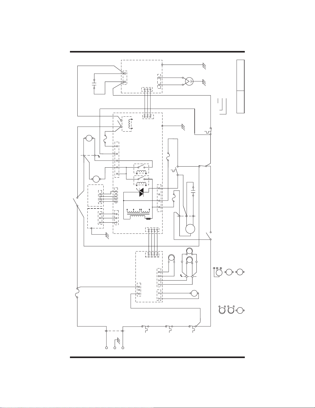
SCHEMATIC
DIAGRAM
37 R16
Filter Capacitor
TT
26 BL22
25 BL22
5P11
29 R16
28 W22
27 B22
External
Keyboard
Interlock
Secondary
8 OR16
FUSE
1 BR16
9 Y16
20 Amp.
Sensor
Humidity
43 Y/G18
38 R22
31 BL22
6P11
SM
7 R22
49 GR22
30 OR22
FUSE
53 OR22
34 R22
35 GR22
P7
1
B
120V / 60Hz
L
0.25 Amp.
47 26AWG/4C
BRW
2P0
50 GR16
P14
1
1
1
G
E
Door
NFS
TT
SM
CL
P7
P5
1P0
W
N
CN702
12
TR1-5101
19 BL22
2 BL16
1100W
4903
4906
4901
L.V.T.
INVERTER
1
46 26AWG/3C
MW Relay
DISPLAY PCB
7103
Sec.
Prim.
40W
1
CN1
Cavity
Thermostat-1
CN701
P2
& POWER PCB
1
45 26AWG/4C
1
INVERTER
1
P3
CN151
CN152
CN153
3 BL16
E701
CN703
GND
HF
HL
L1
1
N1
P12
1
1
41 Y/G18
40 W18
39 W18
42 Y/G18
11 BR22
4 Amp.
FUSE
52 BR22
FUSE
51 G22
17 B22
CL
P22
P22
21 W22
22 Y22
R24
B24
Cavity
Thermostat-2
MAGNETRON
Exhaust Fan
Thermostat
10 BR22
12 Y22
13 W22
14 W22
4 Amp.
16 G22
1P10
W20
B20
TR22
TR22
23 W22
4 BL16
31 BL22
15 R22
3P10
2P10
R20
HF
HL
Y22
HL
Y22
24 W22
2P11
1P11
CF
Cavity
Thermostat-3
Magnetron
Thermostat
Interlock
Motor Capacitor
9 Y16
WIRE SIZE - AWG16
WIRE COLOR - BROWN
WIRE NO. - 1
50 GR16
1 BR16
PINK
BROWN
ORANGE
GRAY
P:
BR:
OR:
GR:
32 BL16
WHITE
GREEN
YELLOW
Y:
G:
W:
TRANSPARENT
BLACK
BLUE
RED
B:
Monitor
33 W16
Primary
Interlock
18 BL16
R:
BL:
TR:
P0/P10/P11:
P2/P3/P5/P7/P12/P14/CN1/CN151/
HOOD EXHAUST
SYMBOL NOTES
WIRE TO WIRE CONNECTORS
CN152/CN153/CN701/CN702/CN703:
WIRE TO PCB CONNECTORS
FAN MOTOR
TURNTABLE
MOTOR
TT
HF
HOOD LAMP
(COOKTOP LAMP)
CAVITY LAMP
HL
CL
CONDITION:
DOOR OPEN
DWG. NO. MU-062 Rev.B
26AWG/3C(4C): RIBBON CABLE/3C(4C)
D.C. COOLING
FAN MOTOR
CF
STIRRER MOTOR
SM
PART NO. 4619-651-97964/8184640 FOR SERVICE TECHNICIAN'S USE ONLY
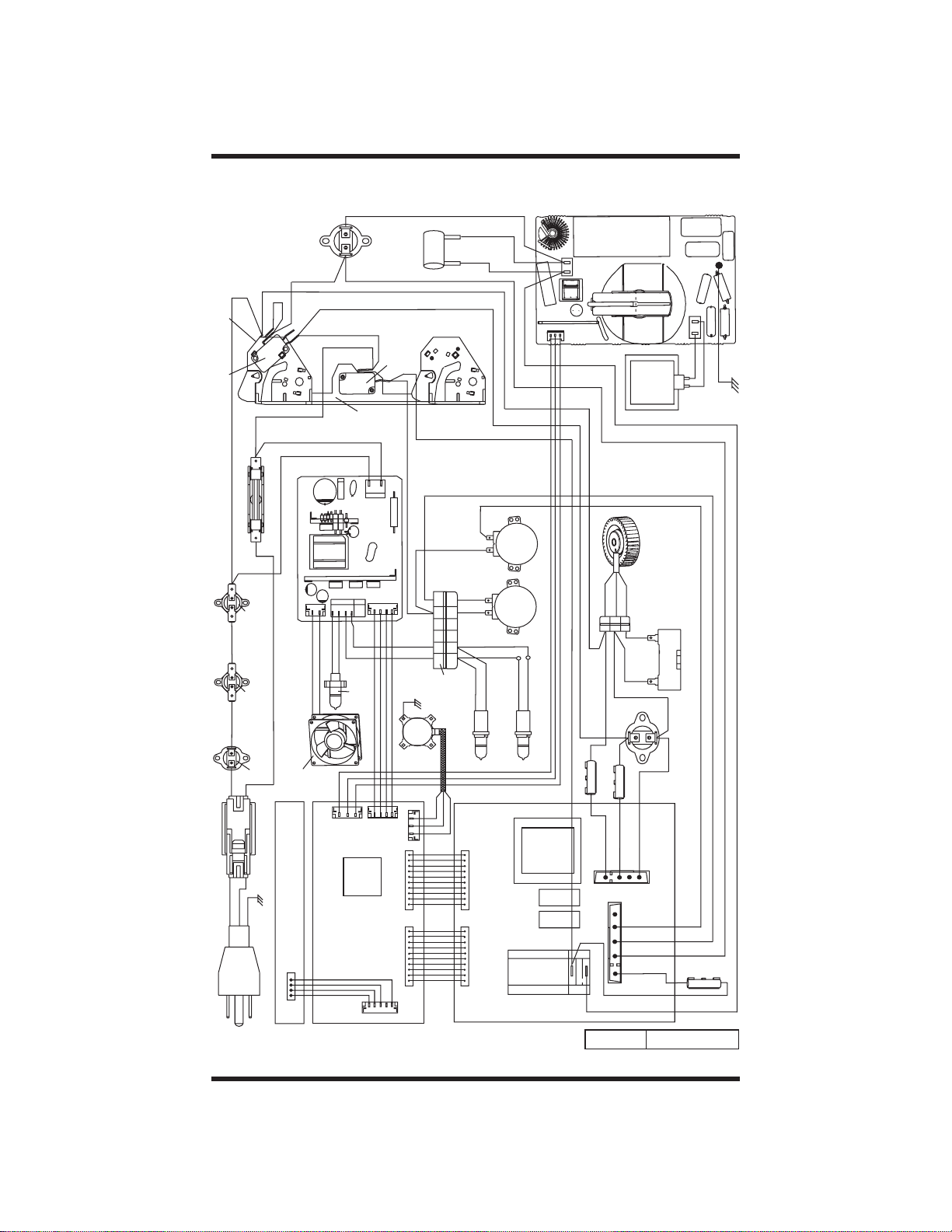
TECH SHEET - DO NOT DISCARD PAGE 3
PICTORIAL DIAGRAM
GRAY
1
CN701
INVERTER
CN702
BLUE
BLACK
1100W
RED
MAGNETRON
CN703
WHITE
WHITE
Y/G
BLUE
INTERLOCK
PRIMARY SWITCH
INTERLOCK
MONITOR SWITCH
BLACK
ORANGE
WHITE
BLUE
RED
MAGNETRON
THERMOSTAT
BLUE BLUE
BROWN
YELLOW
ORANGE
INTERLOCK
SUPPORT
RED
BLUE
FILTER
CAPACITOR
INTERLOCK
SECONDARY
SWITCH
RED
WHITE
GRAY
RED
BLACK
BROWN
BLUE
RED
BLUE
BLUE
BLUE
BLUE
WHITE
FUSE & FUSE SADDLE
BLACK
BROWN
CAVITY
THERMOSTAT-3
CAVITY
THERMOSTAT-2
CAVITY
TWO POLES
GREEN
BROWN
THERMOSTAT-1
CONNECTOR
POWER CORD
BLUE
DC COOLING
EXTERNAL KEYBOARD
P7
40W INVERTER
1
CN153
FAN MOTOR
1
RED
CN152
1
PINK
WHITE
PINK
YELLOW
BLACK
CAVITY LAMP
CAVITY LAMP &
1
P2
MCU
DISPLAY PCB
RIBBON CABLE/4C
P7
CN1
CN151
1
HOLDER
RIBBON CABLE/4C
1
RIBBON CABLE/3C
L.V.T.
MW
4903
TR1 -5101
4901
4906
RELAY
RED
RED
BROWN
BROWN
FUSE &
FUSE SADDLE
2
RED
BLACK
1
BLACK
1
1
GREEN
FUSE &
FUSE SADDLE
GREEN
1
P14
ORANGE
WHITE
2
2
WHITE
WHITE
BROWN
BROWN
1
RED
3
3
RED
P12
ORANGE
HOOD EXHAUST
THREE POLES
CONNECTOR
YELLOW
FAN MOTOR
MOTOR
WHITE
GRAY
CAPACITOR
THERMOSTAT
EXHAUST FAN
GRAY
RED
BLUE
FUSE &
FUSE SADDLE
RED
BLUE
RED
RED
1
GRAY
P3
BLACK
WHITE
YELLOW
WHITE
Y/G
HUMIDITY
SENSOR
1
P5
P21
BLACK
RED
6
5
4
123
SIX POLES
CONNECTOR
BLACK
RED
WHITE
6
5
4
123
BLUE
BLUE
TRANSPARENT
STIRRER
TURNTABLE
WHITE
WHITE
YELLOW
TRANSPARENT
HOLDERS
HOOD LAMP
HOOD LAMPS &
RIBBON CABLE/3C
P21
MOTOR
MOTOR
YELLOW
POWER PCB
P11
1
P11
DWG. NO. L-M1-052 Rev. A
FOR SERVICE TECHNICIAN'S USE ONLY PART NO. 4619-651-97964/8184640
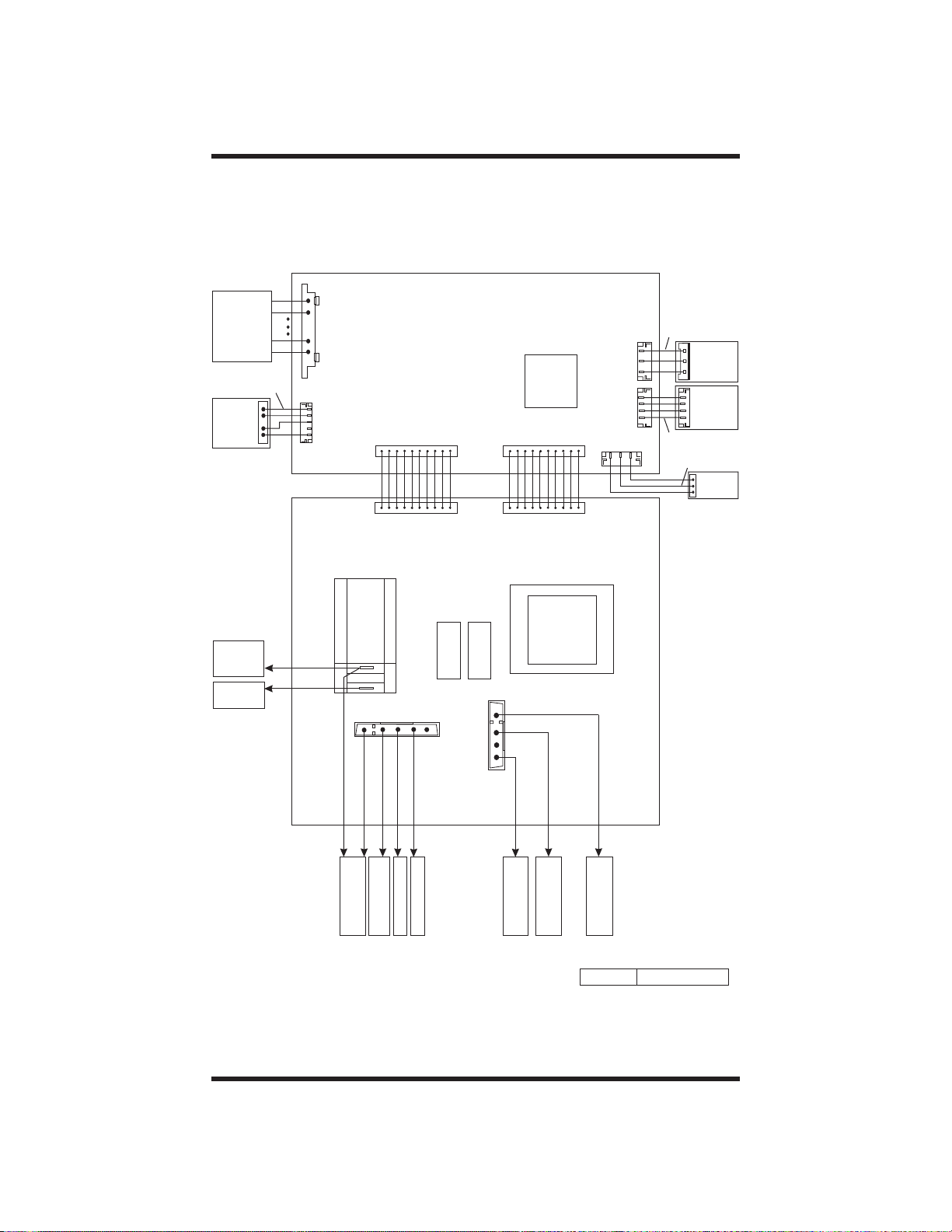
PAGE 4 TECH SHEET - DO NOT DISCARD
PICTORIAL DIAGRAM
Touch Panel
(Membrane
Switch)
Ribbon
Cable/4C
P7
External
Keyboard
Interlock
Secondary
Switch
1100W
Inverter
DISPLAY PCB
P6
1
MCU
P7
1
1
P11 P21
P5
P11 P21
Ribbon
Cable/3C
1
P2
1
P3
1
1
Ribbon
Cable/4C
Red
Black
White
CN701
1
CN151
Humidity
1100W
Inverter
40W
Inverter
Sensor
POWER PCB
Red
Red
4903
MW
RELAY
1
4906
4901
2
1
1
P14
P12
L.V.T.
TR1 -5101
Blue
Red
TT Motor
Magnetron
Thermostat
Gray
Stirrer Motor
Yellow
Thermostat
Exhaust fan
Brown
Fuse
4Amp.
Green
Fuse
4Amp.
Orange
Fuse
Orange
0.25 Amp.
DWG. No. L-M1-054 Rev. A
PART NO. 4619-651-97964/8184640 FOR SERVICE TECHNICIAN'S USE ONLY

TECH SHEET - DO NOT DISCARD PAGE 5
PART S LAYOUT
Not to Scale
Cavity
Thermostat 1
Opens at 165°C (329°F)
Closes at-35°C (-31°F)
(8183999)
Cavity Lamp
(8169418)
Turntable Motor
(4393755)
Hood (Cooktop)
Lamp
(8169418)
Primary Interlock
Switch
(4393599)
Monitor Interlock Switch
(4393697)
Secondary Interlock Switch
(4393599)
Control System Assembly
(Microcomputer)
(8184030)
Membrane Switch/
Control Panel/
Display Lens
(WT 8184228)
(BK 8184231)
(BI 8184230)
(SS 8184229)
Humidity Sensor
(4393808)
Hood (Cooktop)
Stirrer Fan Motor
Lamp
(8169418)
Fuse (0.25 Amp.)
(4393746)
(8184580)
Cavity Thermostat 2
Assembly
Opens at 125°C (257°F)
Closes at-35°C (-31°F)
(8184585)
Filter Capacitor
Fuse (4 Amp.)
(8184579)
Exhaust Fan Thermostat
(8184093)
Opens at 40°C (104°F)
Closes at60°C(140°F)
Hood (Exhaust)
Fan Motor (8183992)
Motor Capacitor
(8184092)
Cavity Thermostat 3
Assembly
Opens at 125°C (257°F)
Closes at -35°C (-31°F)
(8184586)
Magnetron
(8183990)
Magnetron
Thermostat
Opens at 145°C (293°F)
Closes at 105°C (221°F)
(8183994)
Fuse Holder
(4393538)
Line Fuse
(4393308)
110 0W I nverter
(8183997)
40W Inverter
(8184090)
12V Cooling Fan
Motor (8183995)
(8183998)
PRIMARY, MONITOR, AND SECONDARY SWITCH CHECKOUT PROCEDURE
Switch Check By
Primary
Interlock
Secondary
Interlock
1. Disconnect the wires at the Primary Interlock Switch.
2. Check from the common terminal (Blue/Black wires)
to the normally open terminal (White wire).
1. Disconnect the wires at the Secondary Interlock Switch.
2. Check from the common terminal (Orange/Yellow wires)
to the normally open terminal (White/Red wires).
Door
Open
−
−
Door
Closed
+
+
1. Disconnect the wires at the Monitor Switch.
Monitor
2. Check from the common terminal (White/Blue wires)
+
−
to the normally closed terminal (Yellow/Brown wires).
(+) Continuity (–) No Continuity
NOTE: These diagrams are not intended to show a complete circuit; they represent the position
of switches during “DOOR OPEN” and “DOOR CLOSED” (continuity checks only).
DOOR CLOSED
LN
(NC) (NO) (NC)
(NO) (NC) (NO)
SECONDARY
INTERLOCK
SWITCH
MONITOR
SWITCH
PRIMARY
INTERLOCK
SWITCH
FOR SERVICE TECHNICIAN'S USE ONLY PART NO. 4619-651-97964/8184640
DOOR OPEN
LN
(NC) (NO) (NC)
(NO) (NC) (NO)
SECONDARY
INTERLOCK
SWITCH
MONITOR
SWITCH
PRIMARY
INTERLOCK
SWITCH

PAGE 6 TECH SHEET - DO NOT DISCARD
TOUCH PANEL CONTINUITY
DIAGRAM
Example of use: When BEVERAGE is
selected, a resistance of less than 200 ohms
will be observed between 10 and 3 on the flex
circuit connector. See diagram below.
PIN #
7
8
9
10
11
12
13
14
15
16
17
18
1
2
3456
AUTO
DINNER
PLATE
BEVERAGE
FRESH
VEGETABLE
HOLD
WARM
ADD ONE
MINUTE
1
4
COOK
AUTO
REHEAT
FROZEN
VEGETABLE
BREAD
DEFROST
SOFTEN
CLOCK
KITCHEN
2
7
POPCORN
SOUP
MELT
TIMER
5
8
0
TURNTABLE
COOK
TIME
ESD GROUND PLANE
ON/OFF
START
ENTER
ULTRA
DEFROST
FROZEN
ENTREE
BAKED
POTATO
SURE
SIMMER
POWER
OFF
CANCEL
3
6
9
TOUCH PANEL AND
MICROCOMPUTER BOARD TEST
The microwave hood combination is
provided with a self-diagnostic routine that
can be accessed through the touch key
pad. To initiate this routine:
1. Depress the OFF/CANCEL button while
opening the door, and while still
depressing the OFF/CANCEL button,
unplug the microwave oven for two
seconds and plug it back in.
2. Release the OFF/CANCEL button and
then close the door.
3. Now, by pressing each button on the
control panel, “8” will appear in the
display to indicate that the circuits are
complete and all relays are working.
Refer to “Key Table for Test Mode” at
right.
NOTE: If the OFF/CANCEL button is
pressed during this diagnostic routine, you
will exit the test mode.
18 PIN FLEX CIRCUIT CONNECTOR
15 16
18
17 18
1
1234 56 78
91
11 12 13 14
0
KEY TABLE FOR TEST MODE
NOTE: Display position 1 is farthest to the right;
display position 5 is farthest to the left.
Key Name Function
Display
Position*
DINNER PLATE – 5
AUTO REHEAT – 4
AUTO COOK Humidity Sensor ♦
POPCORN – 1
BEVERAGE – 5
ULTRA DEFROST – 4
BREAD DEFROST – 2
SOUP – 1
FROZEN ENTREE – 5
FROZEN VEGETABLE – 4
FRESH VEGETABLE – 2
BAKED POTATO – 1
HOLD WARM – 5
SOFTEN – 4
MELT – 2
SURE SIMMER – 1
ADD ONE MINUTE – 5
(CLOCK) Buzzer 3
KITCHEN TIMER – 1
1 Relay 4901 5
2–3
3 Relay 4903 1
4–5
5–3
6 Relay 4906 1
7–5
8–3
9 Hood Fan Triac 1
COOK TIME – 5
0–3
POWER – 1
TURNTABLE ON/OFF – 5
START/ENTER – 3
(FAN) ON/OFF – 5
(FAN) 5 SPEEDS – 3
(LIGHT)
HIGH/MED/NIGHT/OFF
–1
OFF/CANCEL Exit Test Mode –
* “8” will appear in the display position indicated
in the table.
♦ Eight seconds after pressing AUTO COOK,
“Hmxxx” will appear in the display.
PART NO. 4619-651-97964/8184640 FOR SERVICE TECHNICIAN'S USE ONLY

TECH SHEET - DO NOT DISCARD PAGE 7
TROUBLESHOOTING GUIDE
Complete the following steps before checking
microwave circuitry:
1. Check the line voltage, household fuses or
circuit breakers.
2. Check for loose wiring or miswiring within
microwave.
3. Disconnect white wire from power
transformer and discharge high-voltage
capacitor.
4. All testing must be done with an
ohmmeter having a sensitivity of 20,000
ohms per volt or greater, and powered by
at least a 9-volt battery.
5. All operational checks using microwave
energy must be done with the microwave
oven loaded with a minimum of 300 ml
(10 oz.) of water in a microwave safe
container.
MICROWAVE COOKING
MICROCOMPUTER BOARD
LOW VOLTA GE
TRANSFORMER
BR
BL
P
P
GR
OR
OR
2P12
R
4P14
1P14
TTM RELAY
3P14
DOOR RELAY
MW RELAY
2
1
2
P3
3
DISPLAY PCB
4
POWER PCB
CAVITY LAMP
TR1-5101
4906
4901
4903
&
1P12
2P14
CAPACITOR
R
1
3
1
2
2
P2
3
1
RIBBON CABLE/3C
BL
G
BL
FILTER
RGR
CN702
1100W
INVERTER
CN701
FUSE
4 Amp.
MAGNETRON
THERMOSTAT
GR
CN703
G
BL
W
W
MAGNETRON
B
W
INTERLOCK
PRIMARY
SWITCH
CAVITY
THERMOSTAT
3
BL
BL
CAVITY
THERMOSTAT
BL BL
CAVITY
THERMOSTAT
1
BL
2
W
L1
INTERLOCK
SECONDARY
BR
B
SWITCH
FUSE
20 Amp.
BL
R
Y
OR
1
2
INVERTER
FUSE
4 Amp.
BR
BR
TURNTABLE MOTOR
2.7-3.8K
BL
STIRRER MOTOR
3.3-4.2K
B
FUSE
0.25 Amp.
W
R
1
2
3
4
CN1
1
2
40W
CN153 CN151
1
2
CN152
RIBBON
CABLE/4C
R
D.C. COOLING
FAN MOTOR
B
N
BLOWER FAN TURNS ON AUTOMATICALLY
L1
FUSE
20 Amp.
BBR BROR
EXHAUST FAN
THERMOSTAT
Y
CAPACITOR
WW
W
R
MOTOR
HOOD EXHAUST
FAN MOTOR
R
BB
CAVITY
THERMOSTAT
BL
3
BL
CAVITY
THERMOSTAT
2
CAVITY
THERMOSTAT
1
BL
BL
BLOWER FAN ON (VARIABLE SPEED)
MICROCOMPUTER BOARD
POWER PCB
LOW VOLTAGE
TRANSFORMER
TR1-5101
FUSE
L1
20 Amp.
B
OR
BR
FUSE
4Amp.
Y
BR
BR
BR
2P12
1P12
TRIAC
4P12
7103
B: Black W: White BR: Brown
BL: Blue G: Green OR: Orange
R: Red Y: Yellow GR: Gray
TR: Transparent P: Pink
FOR SERVICE TECHNICIAN'S USE ONLY PART NO. 4619-651-97964/8184640
G
YW
W
R
MOTOR
CAPACITOR
FUSE
4 Amp.
HOOD EXHAUST
FAN M OTOR
W
R
G
CAVITY
THERMOSTAT
3
BL
B
B
BL
THERMOSTAT
CAVITY
2
CAVITY
THERMOSTAT
1
BL
BL
W
N
W
N

PAGE 8 TECH SHEET - DO NOT DISCARD
MICROWAVE PLUGGED IN - TIME OF DAY DISPLAYED
MICROCOMPUTER BOARD
L1
BBR
FUSE
20 Amp.
OR
FUSE
4 Amp.
Y
BR
BR
BR
2P12
DOOR OPEN - CAVITY LAMP IS ON
MICROCOMPUTER BOARD
FUSE
L1
20 Amp.
BBR BR
OR
R
FUSE
4 Amp.
Y
BR
BR
2P12
TRANSFORMER
DISPLAY PCB
&POWER PCB
POWER PCB
LOW VOLTAGE
TRANSFORMER
TR1-5101
LOW VOLTAGE
TR1-5101
CAVITY
LAMP
1P12
1P12
P3
CABLE/4C
1
2
3
4
RIBBON
P
P
R
G
G
1
2
3
4
1
2
FUSE
4 Amp.
FUSE
4 Amp.
G
G
CN151
40W
INVERTER
CN152
CN1
2
1
B
B
CAVITY
THERMOSTAT
3
BL
CAVITY
THERMOSTAT
BL
BL
BL
3
CAVITY
THERMOSTAT
2
BL
CAVITY
THERMOSTAT
2
CAVITY
THERMOSTAT
1
BL
CAVITY
THERMOSTAT
1
BL
N
W
BL
N
BL
W
COOKTOP LAMP ON (VARIABLE LIGHT)
L1
FUSE
20 Amp.
OR
BBR BR
Y
R
BR
FUSE
4 Amp.
BR
2P12
HOOD LAMPS
(COOKTOP LAMPS)
MICROCOMPUTER BOARD
LOW VOLTAGE
TRANSFORMER
TR1-5101
DISPLAY PCB
&POWER PCB
TR
Y
1P12
W
TR
Y
W
1
2
P3
3
4
RIBBON
CABLE/4C
W
Y
G
1
2
3
4
3
4
R
FUSE
4 Amp.
CN151
40W
INVERTER
CN152
CN1
1
G
2
B
BL
CAVITY
THERMOSTAT
3
BL
BL
THERMOSTAT
B: Black W: White BR: Brown
BL: Blue G: Green OR: Orange
R: Red Y: Yellow GR: Gray
TR: Transparent P: Pink
PART NO. 4619-651-97964/8184640 FOR SERVICE TECHNICIAN'S USE ONLY
CAVITY
2
CAVITY
THERMOSTAT
1
BL
BL
N
W

TECH SHEET - DO NOT DISCARD PAGE 9
COMPONENT TESTS
Remove the lead wires from the related
component before conducting any of the
following tests.
All operational checks using microwave
energy must be done with the microwave
oven loaded with a minimum of 300 ml
(10 oz.) of water in a microwave safe
Conduct a microwave energy test after
performing any tests or repairs to the
microwave.
Check that all wire leads are in the
correct position before operating the
microwave oven.
Grasp wire connectors when removing
the wire leads from microwave parts.
container.
COMPONENT / TEST RESULTS
Magnetron
1. Remove wire leads. Check
that the seal is in good
condition.
2. Measure resistance
(ohmmeter scale: Rx1):
Filament terminal - - Normal: Less than 1 ohm
3. Measure resistance
(ohmmeter scale: Rx1000):
Filament to chassis - - Normal: Infinite
D.C. Cooling Fan Motor
1. Remove wire leads.
2. Using an external 9 or
12 DC voltage source,
connect to fan wires:
red wire to ‘+’ and black
Black
Red
wire to ‘–’.
- Fan should work. If not,
replace fan.
Turntable Motor/
Stirrer Motor
1. Remove wire leads.
2. Measure resistance
Digital
Meter
(ohmmeter scale:
Rx1000): Turntable Motor
- Normal: 2700-3800 ohms
(approx.)
COM
- Abnormal: Infinite
Stirrer Motor
- Normal: 3300-4200 ohms
(approx.)
- Abnormal: Infinite
Hood Exhaust Fan
Motor
1. Remove wire leads.
2. Measure resistance
(ohmmeter scale: Rx1): - Normal:
Black - White: 30 - 60 ohms
(approx.)
White
Red
Black - Red: 40 - 80 ohms
(approx.)
- Abnormal: Infinite
Black
FOR SERVICE TECHNICIAN'S USE ONLY PART NO. 4619-651-97964/8184640

PAGE 10 TECH SHEET - DO NOT DISCARD
COMPONENT / TEST RESULTS
Humidity Sensor
White
Red
Black
Resistor
3
2
1
1. Remove the 3-pin connector from PCBA (P5).
Note: Do not remove the attached resistor which is used
for internal resistance calibration.
2. Measure resistance across pins1&3
(ohmmeter scale:Rx1K): - Normal: 2.8K ohms (approx.)
at 25°±10°C (77°±18°F)
- Abnormal: Infinite
3. Measure resistance across pins2&3
(ohmmeter scale:Rx1K): - Normal: 2.8K ohms (approx.)
at 25°±10°C (77°±18°F)
- Abnormal: Infinite
Thermostats
Note: Refer to Parts Layout on page 5 for opening and
closing temperatures.
Cavity
Thermostat
1. Remove wire leads.
2. Cavity and Magnetron
Thermostats:
Measure continuity
(ohmmeter scale: Rx1): - Normal: Continuity
Magnetron
Thermostat
- Abnormal: Infinite
3. Exhaust Fan Thermostat:
Exhaust Fan
Thermostat
Measure continuity
(ohmmeter scale: Rx1): - Normal: Infinite
- Abnormal: Continuity
PART NO. 4619-651-97964/8184640 FOR SERVICE TECHNICIAN'S USE ONLY

TECH SHEET - DO NOT DISCARD PAGE 11
CHECKING INVERTERS
Measure Oven Input Current
Connect an ampmeter to measure the input
current of microwave oven when the power
level is set to Level 10 at the touch panel:
If more than 0.5A, the 1100W inverter
■
is probably okay. Check the magnetron
using test on page 9, and wiring.
If less than 0.5A, there is no input to the 1100W inverter.
■
Check for the following:
No AC voltage supply. Check Control System Assembly PCB and wiring.
–
No control signal. Check Control System Assembly PCB and wiring.
–
15A
Amps
Checking the 1100W Inverter
Note: Do not try to repair the
inverter board, nor try to make
any adjustments to the board.
Check wiring to 1100W
inverter:
120V AC
1. Unplug the oven’s main
power supply.
2. Visually inspect 4 connectors
CN701
on the 1100W inverter board:
CN701, CN702, CN703, E701
to see whether there are any
signs of failure due to loose
wires, bad crimping, signs of
overheating, etc.
Checking the 40W Inverter
Note: Do not try to repair the inverter
board, nor try to make any adjustments
to the board.
Check wiring to 40W
inverter:
1. Unplug the oven’s
main power supply.
2. Visually inspect 4
120V Mains
Input
connectors on the
40W inverter board:
CN1, CN151, CN152,
CN153 to see whether
there are any signs of
failure due to loose wires,
bad crimping, signs of overheating, etc.
CN702
Heat Sink
Control Signal
In/Out
CN1 CN152 CN151
Heat Sink
CN153
CN703
Control Signal Input
12V Halogen Lamps
and Cavity Lamps Output
12V Cooling Fan Output
E701
High Voltage
Output to
Magnetron
FOR SERVICE TECHNICIAN'S USE ONLY PART NO. 4619-651-97964/8184640

PAGE 12 TECH SHEET - DO NOT DISCARD
This page is intentionally blank.
PART NO. 4619-651-97964/8184640 FOR SERVICE TECHNICIAN'S USE ONLY
 Loading...