

Kenmore 650-30643-0 Owner's Manual
Cover
Owner’s Manual
Liquid Propane Gas Grill
Sears Model No.:650-30643-0
400
300
500
600
200
100
700
800
WARNING:
!
Read this Owner’s manual carefully and be
sure your gas grill is properly assembled,
installed and maintained. Failure to follow
these instructions could result in serious injury
and/or property damage. This gas grill is
intended for outdoor use only and is not
intended to be installed in or on recreational
vehicles or boats.
Note to Installer
Leave this Owner’s Manual with the customer
after delivery and/or installation.
Note to Consumer
Leave this Owner’s Manual in a convenient
place for future reference and keep receipt as
proof of purchase to validate the warranty.
Customer Service Helpline:
For questions and warranty parts, call helpline
8 AM to 5 PM EST at:
1-800-469-4663
Date: 2006/02/22
Sears Model No.:650-30643-0
Manufacturer model No: 720-0286
P1
vicinity of this or any other appliance.
Burners:
5 Years
Table of Contents
Warranty------------------------------------------------1
Safety Precautions--------------------------------1~2
Pre-assembly Instructions--------------------------3
Hardware List------------------------------------------4
Parts Diagram -----------------------------------------5
Parts List------------------------------------------------6
Assembly Instructions---------------------------7~10
Lighting Instructions----------------------------11~12
Cleaning and Maintenance-------------------13~14
Trouble Shooting-------------------------------------15
Getting Started With Your Grill-------------------16
Rotisserie Kit Assembly/Use instruction--------17
Cooking Chart-----------------------------------18~20
Recipes Suggestions--------------------------21~23
Kenmore Elite Warranty
Limited Warranty on Grill Parts
Sears will replace the following grill parts at no
charge if they are defective in material or
workmanship and if the parts are still under
warranty. You will be charged for labour.
Component Warranty Period
PRECAUTIONS
WARNING
!
Combustion by products produced when using
this product contain chemicals known to the
State of California to cause cancer, birth defects,
or other reproductive harm.
WARNING
!
Failure to comply with these instructions could
result in a fire or explosion that could cause
serious bodily injury, death, or property damage.
WARNING
!
Your grill will get very hot. Never lean over the
cooking area while using your grill. Do not touch
cooking surfaces, grill housing, lid or any other
grill parts while the grill is in operation, or until the
gas grill has cooked down after use.
Failure to comply with these instructions may
result in serious bodily injury.
WARNING
1. Do not store or use gasoline or other
flammable material and liquids in the
!
Flame Tamers: 3 Years
Cast Iron Cooking Grids: 3 Years
Valves: 1 Year
Frame, Housing, Cart, Control Panel, Igniter, and
Related Parts to Above: 1 Year
All Stainless Steel Parts: 3 Years
All other parts 1 Year
Warranty Service
• Warranty service is available by contacting your
nearest Sears Service Center.
• Warranty Restrictions
This warranty is void if grill is to be used for
commercial or rental purposes.
• This grill is for use with Liquid Propane (LP) gas
only. Any attempt to convert this grill to natural
gas is dangerous and will void your product
warranty.
• This warranty applies only when the grill is used
in Canada.
• This warranty gives you specific legal rights,
and you may also have other rights which vary
from province to province.
Sears Canada Inc.,
Toronto, Ontario
M5B 2B8
2. A LP cylinder not connected for use must
not be stored in the vicinity of this or any
other appliance.
DANGER
If you smell gas:
1. Shut off gas to the appliance.
2. Extinguish any open flame.
3. Open Lid.
4. If odour continues, keep away from the
appliance and immediately call your gas
supplier or your fire department .
Grill Installation Codes
A statement that the installation must conform with
local codes or,in the absence of local codes ,with
either the national fuel gas code ,ANSIZ
223.1/NFPA S4,Natural gas and propane
installation code,CSA B149.1,or propane storage
and handling code,B149.2, or the standard for
Recreational vehicles,ANSI A 119.2,and CSA
Z240 RV series Recreational vehicle code,as
applicable.
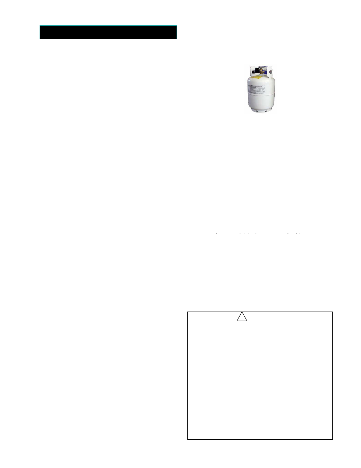
Correct LP Gas Tank Use
LP gas grill models are designed for use with a
standard 20 lb. Liquid Propane Gas tank, not
included with grill. Never connect your gas grill to
an LP gas tank that exceeds this capacity.
!
PRECAUTIONS
not be used under overhead combustible construction . Do
surfaces and dripping grease. Avoid
A tank of approximately 12 inches in diameter by 18-1/2
inches high is the maximum size LP gas tank to use. You
must use an OPD gas tank which offers an Overfill
Prevention Device.
This safety feature prevents the tank from being overfilled
which can cause malfunction of the LP gas tank, regulator
and/or grill.
The LP gas tank must be constructed and marked in
accordance with specifications of the U.S. Dept. of
Transportation (DOT). In Canada, the LP gas tank must
meet the National Standard of Canada ,Can CSA –B339 ,
Cylinders , spheres and Tubes for Transportation of
Dangerous Goods and Commission .
1. The LP gas tank must have a shutoff valve, terminating
in an LP gas supply tank valve outlet, that is compatible
with a Type 1 tank connection device. The LP gas tank
must also have a safety relief device that has a direct
connection with the vapor space of the tank.
2. The tank supply system must be arranged for vapor
withdraw.
3. The LP gas tank used must have a collar to protect the
tank valve.
Proper Placement and Clearance of Grill
Never use your gas grill in a garage, porch, shed,
breezeway or any other enclosed area. Your gas grill is to
be used outdoors only, at least 24 inches from the back
and side of any combustible surface. Your gas grill should
P2
• Never store an LP gas tank indoors. If you store
your gas grill in the garage or other indoor
location, always disconnect the LP gas tank first
and store it safely outside.
• Place dust cap on cylinder valve outlet whenever
the cylinder is not in use. Only install the type of
dust cap on the cylinder valve outlet that is
provided with the cylinder valve. Other types of
caps or plugs may result in leakage of propane.
• LP gas tanks must be stored outdoors in a wellventilated area and out of reach of children.
Disconnected LP gas tanks must not be stored in
a building, garage or any other enclosed area.
• When your gas grill is not in use the gas must be
turned off at the LP gas tank.
• The regulator and hose assembly must be
inspected before each use of the grill. If there is
excessive abrasion or wear or if the hose is cut,
it must be replaced prior to the grill being used
again.
• Keep the gas regulator hose away from hot grill
not obstruct the flow of ventilation air around the gas grill
housing.
This outdoor gas grill is not intended to be installed in or on
recreational vehicles and/or boats.
• Never connect an unregulated LP gas tank to your gas
• grill. The gas regulator assembly supplied with your gas
• grill is adjusted to have an outlet pressure of 11” water
• column (W.C.) for connection to an LP gas tank.
• Only use the regulator and the hose assembly supplied
with your gas grill. Replacement regulators and hose
assemblies must be those specified in this manual.
• Have your LP gas tank filled by a reputable propane gas
• dealer and visually inspected and re-qualified at each
• filling.
• a ) Do not store a spare LP gas cylinder under or
near this appliance.
• b) Never fill the cylinder beyond 80 percent full .
• c) If the information in a) and b) is not followed
exactly a fire causing death or serious injury may
occur.
• Always keep LP gas tanks in an upright position.
• Do not store (or) or use gasoline or other flammable
• vapors and liquids in the vicinity of this gas grill.
•Do not subject the LP gas tank to excessive heat.
unnecessary twisting of hose. Visually inspect
the hose prior to each use for cuts, cracks,
excessive wear or other damage. If the hose
appears damaged do not use the gas grill. Call 1800-361-6665 for a Sears authorized
replacement hose.
• Never light your gas grill with the lid closed or
before checking to ensure the burner tubes are
fully seated over the gas valve orifices.
• Never allow children to operate your grill.
WARNING
A strong gas smell, or the hissing sound of gas
!
indicates a serious problem with your gas grill or the
LP gas tank. Failure to immediately follow the steps
listed below could result in a fire or explosion that
could cause serious bodily injury, death, or property
damage.
• Shut off gas supply to the gas grill.
• Turn the control knobs to OFF position.
• Put out any flame with a proper fire extinguisher.
• Open Grill Lid.
• Get away from the LP gas tank.
• Do not try to fix the problem yourself.
• If odour continues or you have a fire you can not
extinguish, call your fire department. Do not call
from near the LP gas tank because your telephone
is a form of electrical device and could create a
spark resulting in fire and/or explosion.
P3
NOTE: The normal flow of gas through the
regulator and hose assembly can create a
humming noise. A low volume of noise is
perfectly normal and will not interfere with
operation of the grill. If humming noise is loud
and excessive you may need to purge air from
the gas line or reset the regulator excess gas
flow device. This purging procedure should be
done every time a new LP gas tank is
connected to your grill. For help with this
procedure refer to page 13, step 4, or call the
Customer Service Helpline 8 AM to 5 PM EST
at: 1-800-469-4663
CAUTION: Beware of Flash-back
CAUTION: Spiders and small insects
occasionally spin webs or make nests in the grill
burner tubes during transit and warehousing.
These webs can lead to gas flow obstruction
which could result in a fire in and around burner
tubes. This type of fire is known as “FLASHBACK” and can cause serious damage to your
grill and create an unsafe operating condition for
the user.
Although an obstructed burner tube is not the
only cause of “FLASH-BACK”, it is the most
common cause.
To reduce the chance of “FLASH-BACK”, you
must clean the burner tubes before assembling
your grill, and at least once a month in late
summer or early fall when spiders are most
active. Also perform this burner tube cleaning
procedure if your grill has not been used for an
extended period of time.
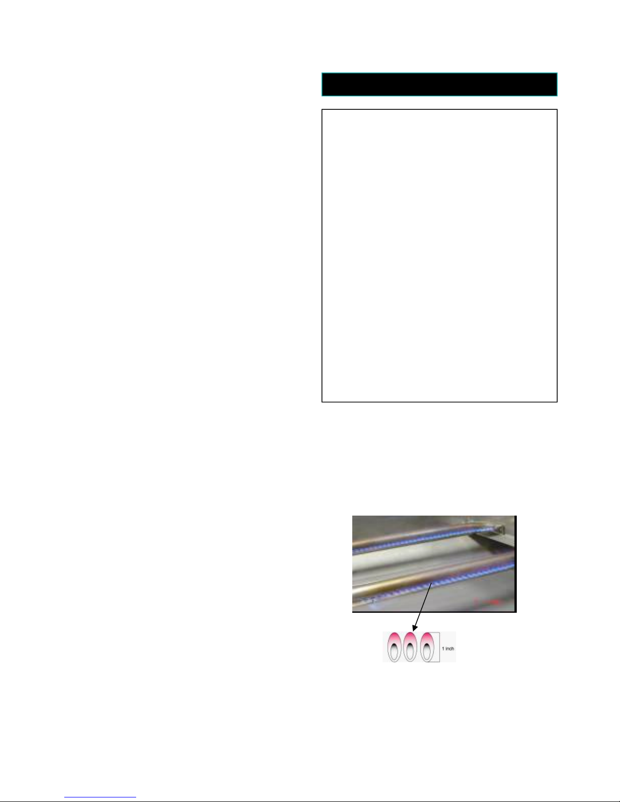
Visually check the burner flames prior to each
use,The flames should look like this picture,if they do
not ,refer to the burner main tenance part of this manual
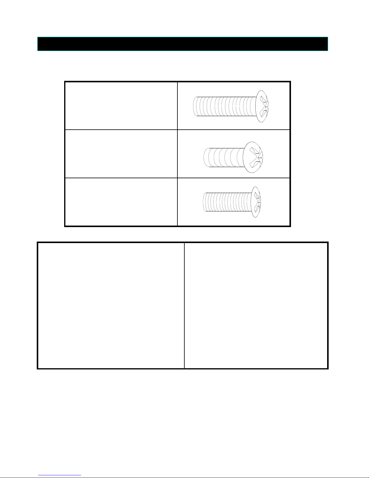
Contents for Hardware Pack (part #643-072)
The following table illustrates a breakdown of the hardware pack. It highlights what components are used in
the various stages of assembly.
¼” x 15mm Philips Head Screw
¼” x 10mm Philips Head Screw
5/32” x 10mm Philips Head Screw
P4
Component Q’ty
¼” x 10mm Philips Head Screw 3
¼” x 10mm Philips Head Screw 3
¼” x 15mm Philips Head Screw 2
¼” x 10mm Philips Head Screw 2
¼” x 15mm Philips Head Screw 2
¼” x 10mm Philips Head Screw 2
5/32” x 10mm Philips Head Screw 1
5/32” x 10mm Philips Head Screw 1
5/32” x 10mm Philips Head Screw 2
¼” x 10mm Philips Head Screw 2
AA Battery 1
Allen Wrench 1
Purpose of Components
Attach Condiment Holder to Left Side Shelf
Attach Side Control Panel to Side Burner Shelf
Attach Left Side Shelf to Fire Box
Attach Right Side Burner to Fire Box
Attach Condiment Holder to Main Control Panel
Attach Side Control Panel to Main Control Panel
Attach Side Valve to Side Control Panel
Attach Side Handle to Left Side Shelf
Powers the Electric Ignitor
Secures Knobs to Valve Heads
03
16
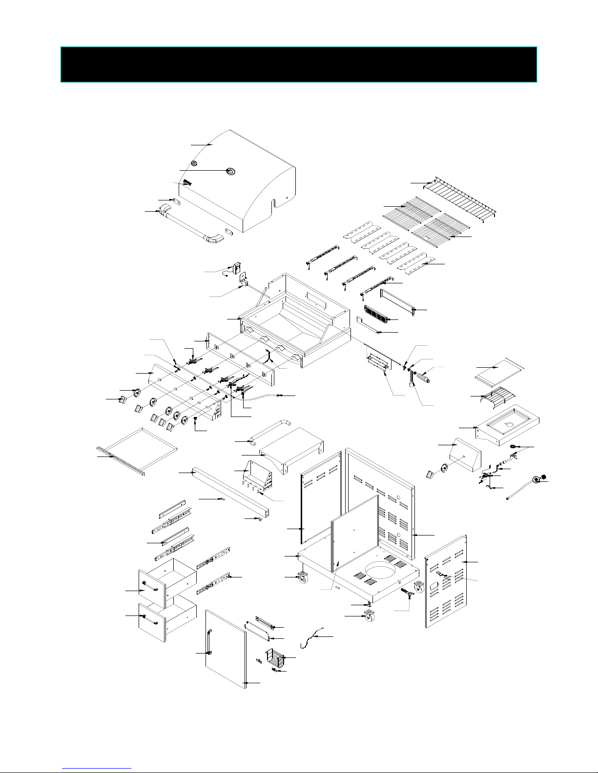
Sears Model 30643 Parts Diagram
P5
(Manufacturer model #: 720-0286)
01
02
44
19
17
15
05
12
11
04
20
09
08
21
71
18
70
06
26
28
27
13
14
29
07
10
45
46
47
48
49
50
51
69
68
67
65
66
52
53
54
55
58
59
56
57
60
22
23
24
25
30
34
43
32
33
31
39
40
42
41
35
37
38
36
61
62
63
64
Sears Model 30643 Parts List
1
(Manufacturer model #: 720-0286)
P6
KEY #
01
02
03
04
05
06
07
08
09
10
11
12
13
14
15
16
17
18
19
20
21
22
23
24
25
26
27
28
29
30
31
32
33
34
35
36
37
PART # DESCRIPTION Q’TY
653-001 Stainless Steel Main Lid 1
653-002 Temperature Gauge 1
653-003 Name Plate 1
653-004 Heat Gasket 2
653-005 Main Lid Handle 1
653-006 Bow l Assembly 1
653-007 Flex Pipe for Rear Burner 1
653-008 Front Baff le 1
653-009 Main Valve 4
653-010 Side Burner Hose 1
653-011 Manifold 1
653-012 Valve clip 5
653-013 Ignitor Wire 1
653-014 Rear Burner Valve 1
653-015 Main Control Panel 1
653-016 Knob Bezel 6
653-017 Knob 6
653-018 Ignitor Button 1
653-019 Grease Tray 1
653-020 Door Support Beam 1
653-021 Door Magnet 1
653-022 Draw er Slider 4
653-023 Draw er 2
653-024 Draw er Handle 2
653-025 Door Handle 1
653-026 Side Push Bar 1
653-027 Left Side Shelf 1
653-028 Condiment Tray 1
653-029 S Hook 4
653-030 Top Door Hinge Bracket 1
653-031 Left Side Panel 1
653-032 Bottom Panel 1
653-033 Caster w ith Brake 2
653-034 Draw er Glide 4
653-035 Center Cart Panel 1
653-036 Bottom Door Hinge Bracket 1
653-037 Caster w ithput Brake 2
KEY #
38
39
40
41
42
43
44
45
46
47
48
49
50
51
52
53
54
55
56
57
58
59
60
61
62
63
64
65
66
67
68
69
70
71
72
73
PART # DESCRIPTION Q’TY
653-038 Lighting Rod 1
653-039 Tow el Holder Bracket 1
653-040 Tow el Holder Hook 1
653-041 Condiment Rack 1
653-042 Condiment Rack bracket 2
653-043 Door 1
643-044 Warming Rack 1
643-045 Left Cooking Grid 1
643-046 Right Cooking Grid 1
643-047 Flame Tamer 4
643-048 Stainless Steel Burner 4
643-049 Rear Casing for Rear Burner 1
643-050 Rear Burner 1
643-051 Gas Collector 1
643-052 Side Burner Lid 1
643-053 Side Burner Cooking Grid 1
643-054 Side Burner Shelf 1
643-055 Side Control Panel 1
643-056 Side Burner 1
643-057 Gas Line 1
643-058 Side Burner Valve 1
643-059 Side Manifold 1
643-060 Regulator and hose 1
643-061 Back Panel 1
643-062 Right Side Panel 1
643-063
643-064 Tank Retention Bolt 1
643-065
643-066
643-067
643-068
643-069
643-070
643-071
643-072
643-073
LP hose retention kit
Spit Fork 2
Counter Balance
Rotisserie Handle
Key Washer
Shaft Collar
Motor Bracket
Rotisserie Motor
Ow ner's Manual
Hardw are Pack
1
1
2
1
1
1
1
1
If you have question about assembly, call the
Customer Service Helpline 8am – 5pm EST,
Monday through Friday at: 1-800-469-4663
For repair and replacement parts you need: 24
hours a day, 7 days a week at:
1-800-4-MY-HOME (1-800-469-4663)
To make sure you obtain the correct replacement
parts for your Kenmore gas grill, please refer to
the part numbers on this page. The following
information is required to assure you receive the
correct parts:
1. Part Number (see REF# in chart)
2. Part Description
3. Quantity of parts needed
Example: 643-001 stainless steel main lid – 1 pc
Important: Keep this Owner’s Manual for convenient
reference and for part replacement.
Important: Use only Sears authorized parts. The use
of any part that is not Sears authorized can be
dangerous and will also void your product warranty.
Sears Model No.:669-30643-0
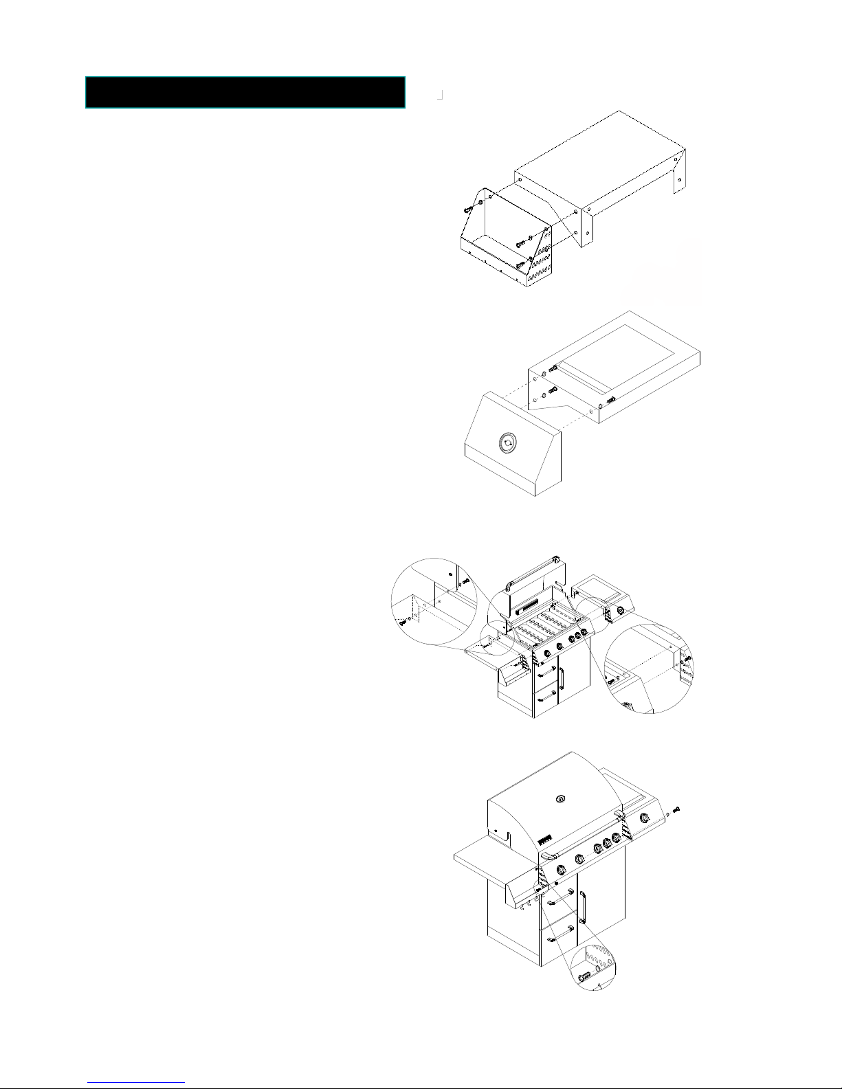
Assembly Instructions
(Fig.1)
Caution: While it is possible for one person to
assemble this grill, obtain assistance from another
person when handling some of the larger, heavier
pieces.
1. Open lid of shipping carton and remove top
sheet of cardboard. Lay cardboard sheet on floor
and use as a work surface to protect floor and grill
parts from scratches.
2. Remove packing materials from shipping carton.
3. You may slice the carton front corners with a
utility knife to lay open the carton front panel. This
will allow you to raise the grill head lid and remove
the components packed inside the head.
4. Use the parts list to check that all parts have
been included.
5. Inspect the grill for damage as you assemble it.
Do not assemble or operate the grill if it appears
damaged. If there are damaged or missing parts
when you unpack the shipping box, or you have
questions during the assembly process, call:
1-800-469-4663
8am – 5pm EST, Monday through Friday.
P7
Figure 1
Figure 2
Installing Side Shelves
1. Attach side condiment holder to left side shelf
by using ¼” x 15mm Philips head screws.
2. Attach side control panel to side burner shelf by
using ¼” x 15mm Philips head screws.
(Fig.2)
3. Attach side shelves to both sides of grill by
using ¼” x 15mm Philips head screws.
(Fig.3)
4. Secure condiment holder to the left of main
control panel by using ¼” x 10mm Philips
head screw. Secure side control panel to the
right of main control panel by using ¼” x
10mm Philips head screw. (Fig.4)
Figure 3
500
600
400
300
700
800
200
100
Figure 4
 Loading...