

Kenmore 625.75130, 625.75230 Use & Care Manual
Use & Care Guide
®
Guide de l’utilisation et d’entretien
English / Français
Models / Modèles 625.75130
625.75230
Kenmore®
Systems tested and certified by NSF
International against NSF/ANSI Standard 44
for hardness reduction, efficiency and the
reduction of barium and radium 226/228,
and certified to NSF/ANSI Standard 372.
Systèmes évalués et certifiés par NSF Inter-
national selon la norme NSF/ANSI 44 pour la
réduction de la dureté de l’eau, l’efficacité et
la réduction de baryum et radium 226/228,
et certifiés selon la norme NSF/ANSI 372.
Systems tested and certified by the Water
Quality Association against CSA B483.1.
Systèmes évalués et certifiés par Water Quality
C
USA
Association selon la norme CSA B483.1.
Water Softener
with Ultra Flow Valve
Adoucisseur d’eau
avec soupape à ultra débit
Sears Canada Inc.
290 Yonge Street
Toronto, Ontario M5B 2C3 Canada
www.kenmorewater.com
www.kenmore.com
www.sears.ca
P/N 7341106 (Rev. D 5/13/14)

Warranty
WARRANTY ON KENMORE WATER SOFTENER
ONE YEAR LIMITED WARRANTY ON WATER SOFTENER
When installed, operated and maintained according to all instructions supplied with the product, if this
Kenmore appliance fails due to a defect in material and workmanship within one year from the date of purchase, call 1-800-4-MY-HOME®to arrange for free repair.
TEN YEAR LIMITED WARRANTY AGAINST LEAKS
When installed, operated and maintained according to all instructions supplied with the product, if the water
softener tank or salt storage drum develops a leak within ten years from the date of purchase,
call 1-800-4-MY-HOME®to arrange for free tank or drum replacement. After the first year you must pay an
initial trip charge.
All warranty coverage does not include water softener resin, which is an expendable item.
If this appliance is used for other than private family purposes, this warranty applies for only 90 days from
the date of purchase.
This warranty covers only defects in material and workmanship. Sears will NOT pay for:
1. A service technician to instruct the user in correct product installation, operation or maintenance.
2. A service technician to clean or maintain this product.
3. Damage to or failure of this product if it is not installed, operated or maintained according to the all
instructions supplied with the product.
4. Damage to or failure of this product resulting from accident, abuse, misuse or use for other than its intend-
ed purpose.
5. Damage to or failure of this product caused by the use of detergents, cleaners, chemicals or utensils other
than those recommended in all instructions supplied with the product.
6. Damage to or failure of parts or systems resulting from unauthorized modifications made to this product.
Disclaimer of implied warranties; limitation of remedies
Customer’s sole and exclusive remedy under this limited warranty shall be product repair as provided herein.
Implied warranties, including warranties of merchantability or fitness for a particular purpose, are limited to
one year or the shortest period allowed by law. Sears shall not be liable for incidental or consequential damages. Some states and provinces do not allow the exclusion or limitation of incidental or consequential damages, or limitation on the duration of implied warranties of merchantability or fitness, so these exclusions or
limitations may not apply to you.
This warranty applies only while this appliance is used in the United States or Canada.
This warranty gives you specific legal rights, and you may also have other rights which vary from state to
state.
Sears Canada Inc., 290 Yonge Street, Toronto, Ontario M5B 2C3 Canada
Questions? Call the Kenmore Water Line 1-800-426-9345 or visit www.kenmorewater.com
2

Table of Contents
Warranty . . . . . . . . . . . . . . . . . . . . . . . . . . . . . . . . . . . . . . . . . . . . . . . . . . . . . . . . . . . . . . . . . . . . . . . . . . . . . . . . . . . . . 2
Safety Guides . . . . . . . . . . . . . . . . . . . . . . . . . . . . . . . . . . . . . . . . . . . . . . . . . . . . . . . . . . . . . . . . . . . . . . . . . . . . . . . . . . 3
Specifications & Performance Claims . . . . . . . . . . . . . . . . . . . . . . . . . . . . . . . . . . . . . . . . . . . . . . . . . . . . . . . . . . . . . . . 4
Dimensions . . . . . . . . . . . . . . . . . . . . . . . . . . . . . . . . . . . . . . . . . . . . . . . . . . . . . . . . . . . . . . . . . . . . . . . . . . . . . . . . . . . . 5
Packing List . . . . . . . . . . . . . . . . . . . . . . . . . . . . . . . . . . . . . . . . . . . . . . . . . . . . . . . . . . . . . . . . . . . . . . . . . . . . . . . . . . . 6
Plan Your Installation . . . . . . . . . . . . . . . . . . . . . . . . . . . . . . . . . . . . . . . . . . . . . . . . . . . . . . . . . . . . . . . . . . . . . . . . . . 6-8
Installation . . . . . . . . . . . . . . . . . . . . . . . . . . . . . . . . . . . . . . . . . . . . . . . . . . . . . . . . . . . . . . . . . . . . . . . . . . . . . . . . . . 8-12
Programming the Softener . . . . . . . . . . . . . . . . . . . . . . . . . . . . . . . . . . . . . . . . . . . . . . . . . . . . . . . . . . . . . . . . . . . . . 13-14
Sanitizing the Water Softener . . . . . . . . . . . . . . . . . . . . . . . . . . . . . . . . . . . . . . . . . . . . . . . . . . . . . . . . . . . . . . . . . . . . 15
Adding Salt to the Storage Tank . . . . . . . . . . . . . . . . . . . . . . . . . . . . . . . . . . . . . . . . . . . . . . . . . . . . . . . . . . . . . . . . . . 15
Controller Features . . . . . . . . . . . . . . . . . . . . . . . . . . . . . . . . . . . . . . . . . . . . . . . . . . . . . . . . . . . . . . . . . . . . . . . . . . . 16-19
Care of Your Water Softener . . . . . . . . . . . . . . . . . . . . . . . . . . . . . . . . . . . . . . . . . . . . . . . . . . . . . . . . . . . . . . . . . . . . . 20
Service Information . . . . . . . . . . . . . . . . . . . . . . . . . . . . . . . . . . . . . . . . . . . . . . . . . . . . . . . . . . . . . . . . . . . . . . . . . . 20-23
Exploded View & Parts List . . . . . . . . . . . . . . . . . . . . . . . . . . . . . . . . . . . . . . . . . . . . . . . . . . . . . . . . . . . . . . . . . . . 24-27
Safety Guides
p Read all steps and guides carefully before installing
and using your new water softener. Follow all steps
exactly to correctly install. Failure to follow them
could cause personal injury or property damage.
Reading this manual will also help you to get all the
benefits from your water softener.
p Your Kenmore water softener will remove hardness
minerals from water. This is measured in grains per
gallon (gpg). It will also remove some clear water
iron*. This is measured in parts per million (ppm).
See the specifications page for the maximum limits
of hardness and iron removal.
p A water softener will not improve other water prob-
lems such as acidity, tastes and odors, or iron other
than clear water iron.
p Do not attempt to use this product to make safe
drinking water from non-potable water sources. Do
not use the system on microbiologically unsafe water,
or water of unknown quality without adequate disinfection before or after the system.
p Check with your local public works department for
plumbing and sanitation codes. You must follow
their guides as you install the system. Follow your
local and provinical codes if they differ with guides
in this manual.
p Use only lead-free solder and flux for all sweat-sol-
der connections, as required by federal codes, when
installing soldered copper plumbing.
p Use care when handling the water softener. Do not
turn upside down or drop.
p Avoid installing in direct sunlight. Excessive heat may
cause distortion or other damage to non-metallic parts.
p This water softener works on water pressures of 20 psi
(minimum) to 100 psi (maximum). If your house water
pressure is over the maximum, install a pressure reducing valve in the water supply pipe to the softener.
p Temperature of the water supply to the softener must be
between 5°C and 49°C. Do not install on hot water.
p If installing the water softener outdoors, do not locate
where it will be exposed to wet weather, direct sunlight
or extreme hot or cold temperatures.
p This softener works on 24 volt, 60 Hz electrical power
only, supplied by a direct plug-in transformer (included). Be sure to use the included transformer and plug
it into a nominal 120V, 60 cycle household outlet that
is properly protected by an overcurrent device such as
a circuit breaker or fuse. If transformer is replaced,
use only the authorized service, Class II, 24V 10VA
transformer.
p This water softener has a non-metallic valve system.
Installing it on metal plumbing will break electrical
continuity, which may interrupt grounding for the
home. You must restore electrical continuity in your
metal plumbing system (See Page 12).
* The capacity to reduce clear water iron is substantiated
by Water Quality Association test data.
European Directive 2002/96/EC requires all electrical and electronic
equipment to be disposed of according to Waste Electrical and Electronic
Equipment (WEEE) requirements. This directive or similar laws are in
place nationally and can vary from region to region. Please refer to your
state and local laws for proper disposal of this equipment.
Questions? Call the Kenmore Water Line 1-800-426-9345 or visit www.kenmorewater.com
3
Specifications & Performance Claims
These models are efficiency rated. The efficiency rating is valid only at the minimum salt dose. These softeners have
a demand initiated regeneration (D.I.R) feature that complies with specific performance specifications intended to
minimize the amount of regenerant brine and water used in their operation.
These softeners have a rated softener efficiency of not less than 3,350 grains of total hardness exchange per pound of
salt (based on sodium chloride) and shall not deliver more salt than their listed rating or be operated at a sustained
maximum service flow rate greater than their listed rating. These softeners have been proven to deliver soft water for
at least ten continuous minutes at the rated service flow rate. The rated salt efficiency is measured by laboratory tests
described in NSF/ANSI Standard 44. These tests represent the maximum possible efficiency that the system can
achieve. Operational efficiency is the actual efficiency after the system has been installed. It is typically less than the
rated efficiency, due to individual application factors including water hardness, water usage, and other contaminants
that reduce a softener's capacity.
SPECIFICATIONS
Model Nos. 625.75130 & 625.75230
Model Code hF32
Rated Softening Capacity (Grains @ Salt Dose)
Rated Efficiency (Grains/Pound of Salt @ Minimum Salt Dose) 4,565 @ 2.3 lbs.
Water Used During Regeneration @ Minimum Salt Dose 3.6 gallons / 1,000 grains
Total Water Used Per Regeneration @ Maximum Salt Dose 38.1 gallons
Rated Service Flow Rate 10.0 gpm
Amount of High Capacity Ion Exchange Resin 1.08 cu. ft.
Pressure Drop at Rated Service Flow 11 psig
Water Supply Max. Hardness 95 gpg
Water Supply Max. Clear Water Iron 8 ppm
Water Pressure Limits (minimum / maximum) 20 - 100 psi
Water Temperature Limits (minimum / maximum) 5 - 49 °C
Minimum Water Supply Flow Rate 3 gpm
Intermittent Flow @ 15 psi 10.0 gpm*
Maximum Drain Flow Rate 2.0 gpm
10,500 @ 2.3 lbs.
27,600 @ 8.5 lbs.
35,000 @ 14.7 lbs.
* Intermittent flow rate does not represent the maximum service flow rate used for deter -
mining the softener’s rated capacity and efficiency. Continuous operation at flow rates
greater than the service flow rate may affect capacity and efficiency performance.
These systems conform to NSF/ANSI Standard 44 for the specific performance claims as
verified and substantiated by test data.
Variable Salt Dose: The salt dose is selected by the electronic controls at regeneration
time based on the amount needed.
Contaminant Influent Challenge Level
Barium 10 ±10% mg/L 2.0 mg/L
Radium 226/228 25 pCi/L 5 pCi/L
Questions? Call the Kenmore Water Line 1-800-426-9345 or visit www.kenmorewater.com
4
PERFORMANCE CLAIMS
Maximum Allowable
Product Water Level
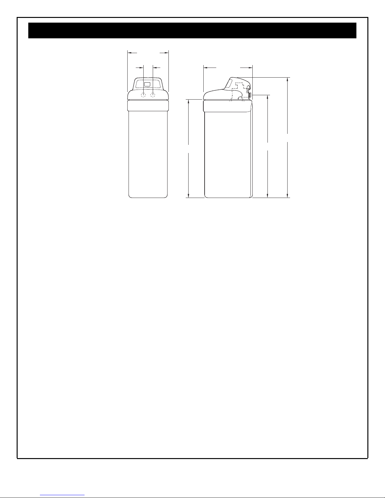
3-3/4"
INOUT
48"
41-1/2"
IN - OUT
19-3/4"
40-1/4"
SIDE VIEWFRONT VIEW
16-1/2"
OUT
41.9 cm
9.5 cm
Dimensions
IN
102.2 cm
50.2 cm
IN - OUT
121.9 cm
105.4 cm
FRONT VIEW
SIDE VIEW
Figure 1
Questions? Call the Kenmore Water Line 1-800-426-9345 or visit www.kenmorewater.com
5
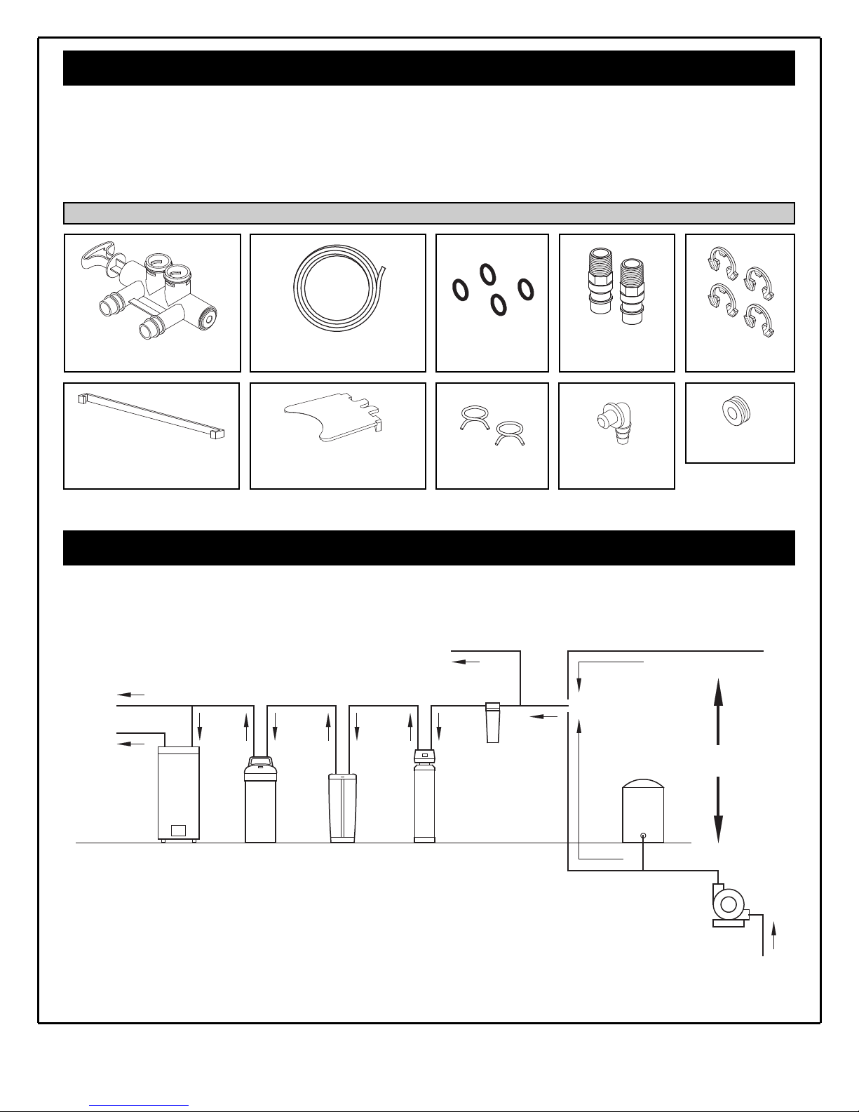
Packing List
The parts required to assemble and install the water
softener are included with the unit. Thoroughly check
the water softener for possible shipping damage and
parts loss. Also inspect and note any damage to the
shipping carton.
Drain HoseBypass Valve
Cover Lock
(for shipping only)
Rim Insert
(for shipping only)
Remove and discard (or recycle) all packing materials.
To avoid loss of small parts, we suggest you keep the
small parts in the parts bag until you are ready to use
them.
Small Parts
Hose Clamps
O-rings
Installation
Adaptors
Adaptor Elbow
Clips
Grommet
Figure 2
Plan Your Installation
THE PROPER ORDER TO INSTALL WATER TREATMENT EQUIPMENT
(Shows sequence of equipment only - not all items are needed in all applications)
Cold Water
to House
Hot Water
to House
Water
Heater
= Always locate an Iron Filter UPSTREAM of the water softener.
= Locate a Central Water Filtration System UPSTREAM of the water softener on a chlorinated
water supply, or DOWNSTREAM of the water softener on a non-chlorinated water supply.
Water
Softener
Untreated Water to
Outside Faucets
Central
Water
Filtration
System
Iron
Filter
Sediment
Cartridge
Filter
Pressure
City Water Supply
Tank
Well Water Supply
Well
Pump
OR
Figure 3
Questions? Call the Kenmore Water Line 1-800-426-9345 or visit www.kenmorewater.com
6
Outside Faucet
(hard water)
Soft, cold water)
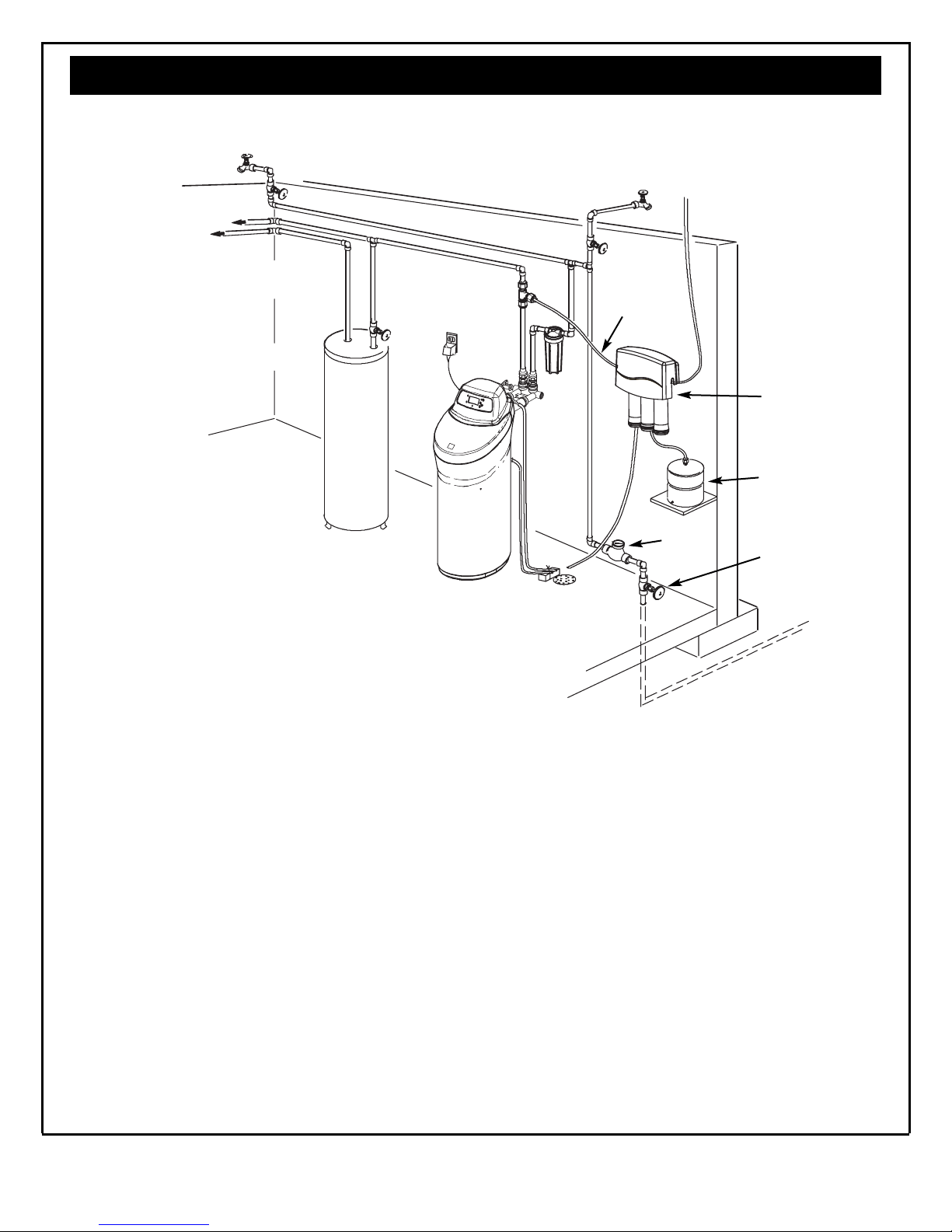
Plan Your Installation
TYPICAL INSTALLATION
Outside Faucet
(hard water)
Hard Water Line
to R.O. Faucet
Soft, hot water
Water
Heater
Soft Water Line
Shutoff
120V,
60 Hz
Water
Softener
Valve
Hard
Water
House
Floor
Drain
to
4 cm
Air Gap
Soft Water
to R.O.
System
R.O. Drain
Water
Meter
Reverse
Osmosis
System
R.O.
Storage
Tank
Main
Shutoff
Valve
Figure 4
WHERE TO INSTALL THE WATER SOFTENER
Review the following points before you choose a place
to put your softener:
1. Place as close as possible to, but always downstream
from, the pressure tank (well water) or water meter
(city water).
2. Place as close as possible to a water drain such as a
floor drain, laundry tub, sump or standpipe (See Fig.
4).
3. Connect to the house main water pipe UPSTREAM
OF THE WATER HEATER (See Fig. 3). The temperature of water going through the softener must not be
more than 49°C (120°F). Hot water will damage
inner softener parts. To reduce the risk of hot water
backup, piping between the softener and water
heater should be as long as possible.
4. Keep outside faucets on hard water to save soft
water and salt. See Fig. 4.
5. Do not install in a place where the softener could
freeze. Damage caused by freezing voids the warranty by Sears Canada Inc.
6. Put the softener in a place where water damage is
least likely to occur if it develops a leak. Sears or
the manufacturer will not repair or pay for water
damage.
7. A grounded, 120V, 60 Hz. electrical outlet is needed
near the softener to plug in the transformer
(See Fig. 4). Be sure the outlet and transformer are
in an inside location, protected from wet weather.
Use a continuously “live” outlet, which cannot be
accidentally switched off.
8. When installing in an outside location, you must take
the steps necessary to assure the softener, installation
plumbing, and wiring, are protected from the elements, direct sunlight, contamination, vandalism, etc.
Questions? Call the Kenmore Water Line 1-800-426-9345 or visit www.kenmorewater.com
7
Plan Your Installation
CHECK YOUR WATER PRESSURE BEFORE INSTALLING
For your water softener to work properly, incoming
water pressure in your house pipes must be no lower
than 20 pounds per square inch (psi). The highest
allowable pressure is 100 psi. If pressure is above 100
psi, buy and install a pressure reducing valve in the
pipe supplying water to the softener’s inlet.
NOTE: If water pressure during the day is 80 psi or
more, pressure during the night may go above
100 psi.
Installation
INSTALL SINGLE BYPASS VALVE AND/OR THREADED INSTALLATION ADAPTORS
Complete the following steps to assemble the adaptors
and/or the included single bypass valve.
1. Close the shutoff valve on the house main water pipe,
near the water meter or pressure tank, to turn off the
water.
2. Shut off the gas or electric supply to the water
heater.
3. Open the highest and lowest water faucets in your
house. This will let water drain from the pipes.
Close faucets after water has drained.
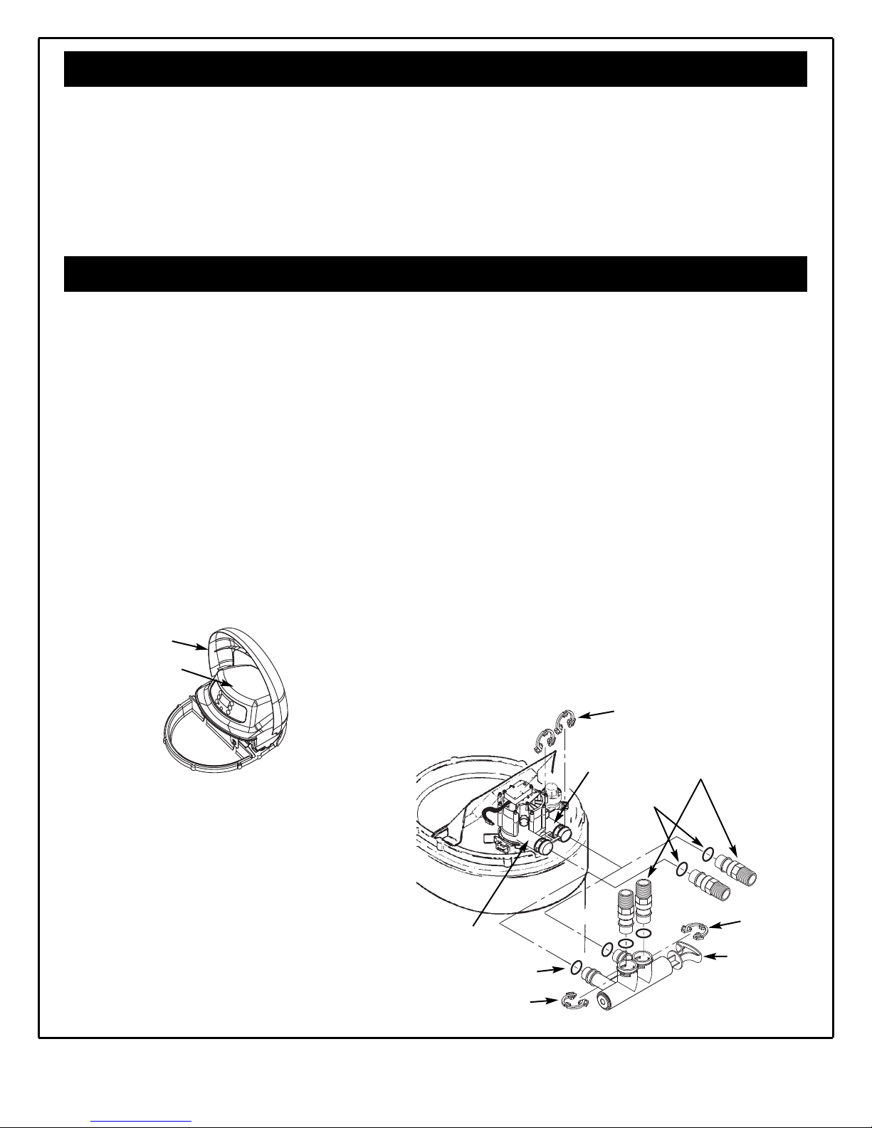
4. Remove the top cover. Pull outward on the two tabs
to release top cover (see Fig. 5). The salt lid remains
attached to the top cover when removed. Set both
covers aside so they will not get scratched or broken.
Salt Lid
Top Cover
SINGLE BYPASS VALVE:
6. Lightly coat the o-rings with silicone grease and slide
them onto the bypass valve. Push the bypass valve
into the softener valve’s inlet and outlet ports as far
as it will go. Snap the two large holding clips into
place, from the top down as shown (see Fig. 8).
CAUTION: Be sure the clips snap firmly into place so
the bypass valve will not pull out.
INLET AND OUTLET THREADED ADAPTORS:
7. Lightly coat the o-rings with silicone grease and slide
them onto the installation adaptors. Push the adaptors into the valve inlet and outlet ports, or bypass
valve ports, as far as they will go. Both adaptors are
the same and fit either port. Snap the two large
holding clips into place, as shown (see Fig. 8).
CAUTION: Be sure the clips snap firmly into place so
the adaptors will not pull out.
5. Visually check and remove any foreign mate-
rials from the valve inlet and outlet ports (see
Fig. 6). Carefully remove the two large plastic
clips (you will use them). Check to be sure
the turbine and support are firmly in place
(see Fig. 7).
NOTE: If you will not install the included bypass
valve because you will have a 3-valve
bypass in your plumbing, skip step 6, but
perform step 7.
Questions? Call the Kenmore Water Line 1-800-426-9345 or visit www.kenmorewater.com
8
Figure 5
Valve Inlet
O-Rings
Clip
Valve
Outlet
O-Rings
Clips
Threaded
Installation
Adaptors
Clip
Single
Bypass Valve
Figure 6
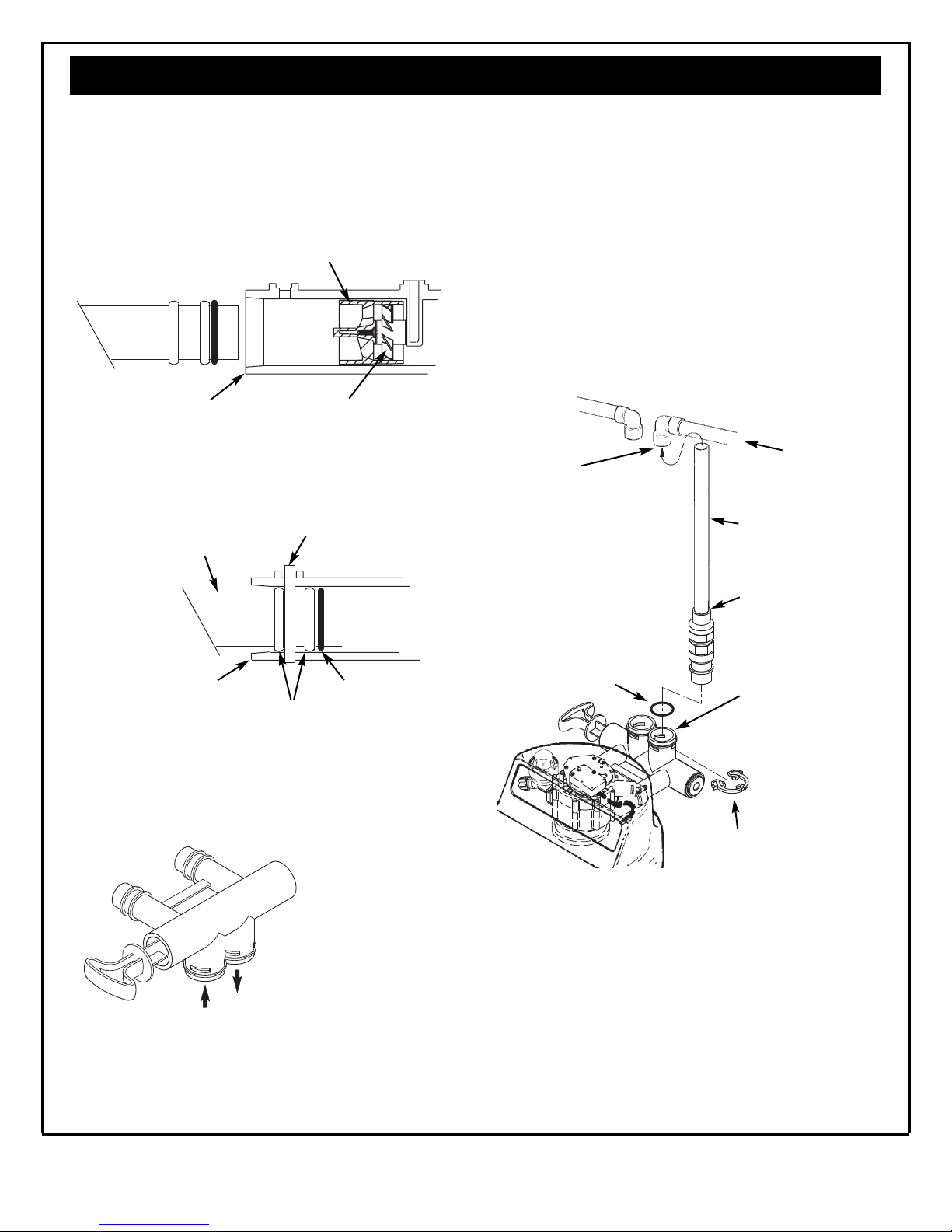
Installation
INSTALL SINGLE BYPASS VALVE (cont.)
Before installing the bypass valve and/or installation
adaptors, make sure that the turbine and support are
firmly in place inside the softener valve’s outlet port.
Turbine
Support
Valve Outlet Turbine
Figure 7
INSTALL HOLDING CLIPS
Bypass Valve or
Installation Adaptor
Plastic Clip
ASSEMBLE INLET AND OUTLET PLUMBING
Measure, cut (thread if needed) and put together all
pipe and fittings up to the main water pipe. Make sure
that the incoming water supply pipe goes to the valve
inlet side.
CAUTION: Never solder fittings while connected to
nonmetallic parts. Wait until soldered pipe
has cooled before connection. See Fig. 10.
CAUTION: Be careful when putting pipe fittings togeth-
er. Do not cross thread, and do not overtighten.
Main Water Pipe
Incoming
Hard
4. Solder.
NOTE: To be certain
that heat will not
travel down the pipe
and into the bypass
valve or installation
adaptors, wrap the
bottom of the pipe
and the bypass valve
with a wet rag.
Water
1. Cut pipe to
correct length
2. Solder. When
cool, do step 3.
Valve Inlet or Outlet
Plastic clip snaps
into groove in
bypass or adaptor
O-Ring
Figure 8
ALTERNATE BYPASS VALVE INSTALLATION
If connecting to floor
level plumbing, install
the bypass valve turned
downward, as shown.
OUT
IN
Figure 9
O-Ring
IN
3. Put threaded
adaptor into
bypass valve
port.
Clip
Figure 10
Questions? Call the Kenmore Water Line 1-800-426-9345 or visit www.kenmorewater.com
9
 Loading...