

Page 1
OWNER’S
MANUAL
MODEL NO.
625.348261
Caution:
Read and Follow
All Safety Rules and
Operating Instructions
Before First Use of
This Product.
If you have questions when
installing, operating or main
taining your filter, and when
setting the timer, call this
toll-free number...
1-800-426-9345
(M - F, 7 am - 8 pm, CST)
For repair or replacement
parts, call this toll-free num
ber...
1-800-366-7278
See back cover for other
Sears service numbers.
www.KenmoreWater.com
SAVE THIS MANUAL
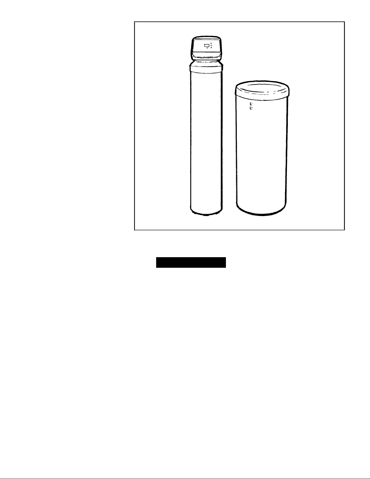
KGtimorG
Tannin Water Filter
♦ Warranty
♦ Start Up / Setting Timer
♦ How It Works
♦ Care Of
♦ Specifications
♦ Repair Parts
Sears, Roebuck and Co., 3333 Beverly Road, Hoffman Estates, IL 60179 USA
PRINTED IN U.S.A.
Part No, 7282572 {Rev. A 5/11/06)
Page 2

WARRANTY
SEARS RESIDENTIAL WATER FILTER
FULL ONE YEAR WARRANTY ON FILTER
For one year fronn the date of purchase, when this filter is installed and maintained
in accordance with our instructions, Sears will repair, free of charge, defects in
material or workmanship in this water filter.
FULL TEN YEAR WARRANTY AGAINST LEAKS
For ten years from the date of purchase. Sears will furnish and install a new current
model water filter tank or salt storage drum, free of charge, if either the tank or drum
develop a leak.
TOOBTAINWARRANTYSERVICE, SIMPLY CONTACTTHE NEAREST SEARS
SERVICE CENTER THROUGHOUT THE UNITED STATES. This warranty
applies only while this product is in use in the United States.
This warranty gives you specific legal rights, and you may have other rights which
vary from state to state.
Sears, Roebuck and Co., D/817 WA, Hoffman Estates, IL 60179
If you want your water filter professionally installed, talk to your Sears Salesman. He will arrange for a
prompt, quality installation by Sears Authorized installers.
SEARS INSTALLATION POLICY
All installation labor arranged by Sears shall be per
formed in a neat, workmanlike manner in accor
dance with generally accepted trade practices. Fur
ther, all installations shall comply with all local laws,
codes, regulations and ordinances. Customer shall
also be protected, during installation, by insurance
relating to Property Damage, Workman's Com
In addition to any warranty extended to you on the
Sears merchandise involved, which warranty be
comes effective the date the merchandise is
installed, should the workmanship of any Sears ar
ranged installation prove faulty within one year.
Sears will, upon notice from you, cause such faults
to be corrected at no additional cost to you.
SEARS INSTALLATION WARRANTY
pensation and Public Liability.
FACTS AND FIGURES TO KEEP
Fill in the blanks below and keep this book in a safe place so you always have
these facts.
Water Filter Model No.t_______________________________________
Serial Number
Date Installed
Water Hardness
Iron Content
Tannin
_________
pH
__________
Water Pressure
Water Flow Rate
t The model number is on the rating decal, located on the rim, under the salt hole cover.
_______________________________________________
Grains Per Gallon
____
Taste And/ Or Odor
_Parts Per Million
Parts Per Million
Pounds/Square Inch
Gallons Per Minute
Page 3

TABLE OF CONTENTS
SECTION 1 WATER FILTER START UP PAGE NO.
A. Safety Guides.......................................................................................................... 1-1
B. Gheck List of All Step-By-Step Guides to Install ............................................... 1-2
C. Program the Timer ................................................................................... 1-3&1-4
D. Sanitizing the Water Filter..................................................................................... 1-5
SECTION 2 HOW YOUR WATER FILTER WORKS
A. Faceplate Timer Features............................................................................. 2-1 & 2-2
B. Filtered Watep Service and Regeneration
.................................................
2-3 & 2-4
SECTION 3 CARE OF YOUR FILTER
A. Checking the Salt Storage Level and Refilling
B. Breaking a Salt Bridge ........................................................................................... 3-1
C. Cleaning the Filter Resin Bed ............................................................................... 3-2
D. Cleaning the Nozzle & Venturi............................................................................. 3-2
E. Keep the Filter From Freezing
F. Helpful Hints Checklist - Before You Call for Service ...................................... 3-4
.............................................................................
...................................................
3-1
3-3
SECTION 4 OTHER THINGS TO KNOW
A. Dimensions / Specifications................................................................. 4-1 & 4-2
SECTION 5 SERVICE TECH. INFORMATION
A. Wiring Schematic ................................................................................................... 5-1
B. Troubleshooing - Manual Initiated Electronics Diagnostics 5-2
B. Troubleshooing - Manual Advance Diagnostics................................................ 5-3
C. Rotary Valve Service............................................................................................... 5-4
D. Water Flow Through the Filter Valve........................................................ 5-5 to 5-7
SECTION 6 REPAIR PARTS 6-1 to 6-4
B
Page 4

SECTION 1
WATER FILTER START UP
A. SAFETY GUIDES
^ Read all steps, guides and rules carefully before installing and using
your new water filter. Follow all steps exactly to correctly install. Failure
to follow them could cause personal injury or property damage. Reading
this book will also help you to get all of the benefits from your water filter,
^ Your tannin filter will remove tannins from your water supply as de
scribed on page 4-2. Also see the specifications on page 4—1. It will
not soften hard water, purify contaminated water, or make other unsafe
water safe to drink. The tannin removal resin will foul or deteriorate if
supply water exceeds any of the limitations as specified on page 4-1.
Pretreatment my be needed.
^ Protect the filter and piping from freezing. Damage from freezing
voids the filter warranty. See page 3-3.
^ Connect the filter to the house COLD water (120° max.) pipe only.
DO NOT CONNECT TO HOT WATER. Hot water will damage Inner parts
and weaken or break the tank.
CAUTIONS
PLEASE READ AND COMPLY WITH THE FOLLOWING GUIDES TO
PREVENT DAMAGE TO THE FILTER OR OTHER PROPERTY PER
SONAL INJURY, OR POSSIBLE FATAL SHOCK.
A THIS FILTER WORKS ON 24 VOLTS ONLY BE SURE TO USE
THE TRANSFORMER INCLUDED, AND PLUG IT INTO A
GROUNDED 120V OUTLET.
A Unplug the transformer right away if the power cable should
become damaged or frayed. Make repairs before plugging back
into the power outlet.
A Always unplug the filter from electrical power before removing
outer valve covers.
European Directive 2002/96/EC requires all electrical and elec
tronic equipment to be disposed of according to Waste Electrical
and Electronic Equipment (WEEE) requirements. This directive or
K
similar laws are in place nationally and can vary from region to
region. Please refer to your state and local laws for proper disposal of
this equipment.
1-1
Problems, Questions? Call 1-800-426-9345 Kenmore Water Line
Page 5
SECTION 1
WATER FILTER START UP
B. CHECK LIST OF ALL STEP-BY-STEP GUIDES TO INSTALL
Refer to the Installation Manual, part number
7146611, for step-by-step guides.
To be sure you have done all the steps to install
the filter, read the following list. Page numbers
referred to are in the Installation Manual.
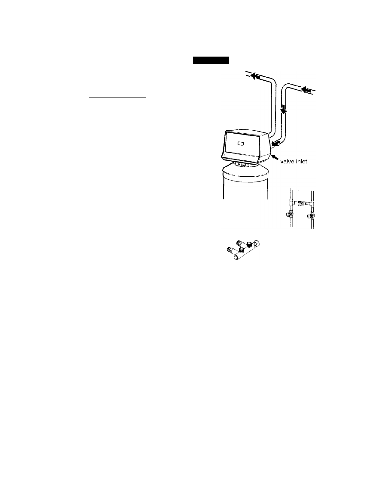
y" Is the house water flow going INTO the filter
valve INLET? Trace piping to be sure . . . page
9.
K' Is the plumbing bypass valve (or three valves)
set for SERVICE? . . . See Figure 13, page 4-1 of
this manual.
K' Is the valve drain hose connected the right
way, and without sharp bends or kinks that
could stop or reduce water flow? . . . page 14.
y" Is the transformer plugged into an inside, con
tinuously "live", grounded, 120V-60Hz electri
cal outlet. . . page 17.
y* Be sure to restart the water heater . . . page 18.
FIGURE 1
water
supply
Uil
1-2
Problems, Questions? Call 1-800-426-9345 Kenmore Water Line
Page 6
SECTION 1
C. PROGRAM THE TIMER
WATER FILTER START UP
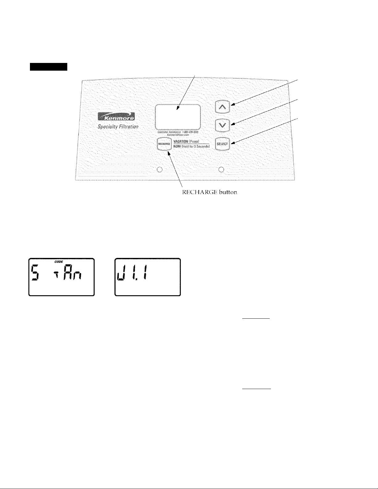
FIGURE 2
When the transformer is plugged into the electri
cal outlet a model code is displayed for a few sec
onds followed by a test number (example: Jl.l).
Then, 12:00 PM and the words PRESENT TIME
will begin to flash in the time display.
display
UP button
DOWN button
SELECT button
1. SET PRESENT TIME OF DAY
Press the UP or DOWN buttons to set the present
time. Press UP to move the display ahead; press
DOWN to move the time backward.
Notes:
If
---------DOWN button until "S tAn" shows in the display.
Then, press the SEEECT button to set, and change
to the flashing PRESENT TIME display.
To check the model code, unplug the transformer
at the wall outlet and plug in again, if other than
this code shows, see page 5-2 to reset.
If the words PRESENT TIME do not show in the
display, press the SELECT button (FIGURE 2) un
til they do.
SOUND "BEEPER": A "beeper" sounds while
pressing buttons for set-up. One beep signals a
change in the face plate display Repeated beeps
mean the timer will not accept a change from the
button you have pressed, telling you to use anoth
er button.
shows in the display, press the UP or
a. If the present time is between noon and mid
night, be sure PM shows.
U€ 0
l‘JU p"
rofSEIT
TIME
b. If the present time is between midnight and
noon, be sure AM shows.
i I* J(L AM
I i-IiO
PBESEii TIME
Each press of the UP or DOWN buttons changes
the time by 1 minute. Holding the buttons in
changes the time 32 minutes each second.
C. Press the SELECT button once to set the pres
ent time of day and advance to the next set up
screen.
1-3
Problems, Questions? Call 1-800-426-9345 Kenmore Water Line
Page 7
SECTION 1
C. PROGRAM THE TIMER
WATER FILTER START UP
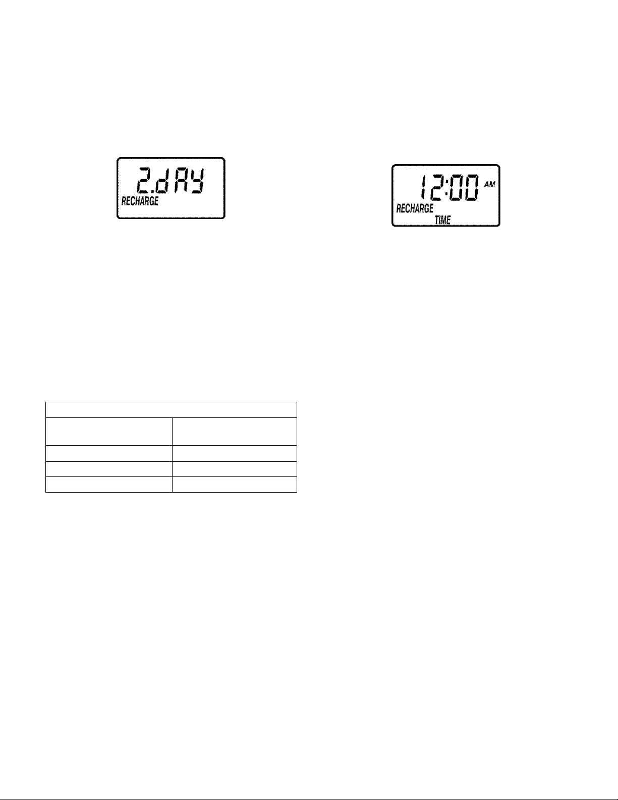
2. SET DAYS TO RECHARGE
This setting is the number of days the fitter wiit go
between recharges. The defauit setting is 2 days,
with a maximum setting of 99.
Press the UP or DOWN buttons untii the cor
rect number of days between recharges is
shown in the dispiay.
b.
Press the SETECT button once to set the days
to recharge and advance to the next set up
screen.
See the chart beiow to determine the frequency of
recharges. Find the number of peopie iiving in the
househoid, and then going across the chart, find
the number of days that the fitter shoutd be set for
recharges.
3. SET RECHARGE TIME
The fitter is factory set to begin recharge at 12:00
AM. If a different recharge time is desired, or
needed, do the foiiowing.
a. Press the UP or DOWN buttons untii the cor
rect recharge time is shown in the dispiay.
b. Press the SETECT keypad once to set the re
charge time and return the dispiay to the normat operating screen with the present time of
day shown.
Regeneration Tabie
Number of Peopie in
Househoid
1 - 3 3 days
4 - 6 2 days
7- 10 1 days
Days to Recharge
setting
1-4
Problems, Questions? Call 1-800-426-9345 Kenmore Water Line
Page 8
SECTION 1
WATER FILTER START UP
D. SANITIZING THE WATER FILTER
Care is taken at the factory to keep your water fil
ter clean and sanitary. Materials used to make the
filter will not infect or contaminate your water
supply and will not cause bacteria to form or
grow. However, during shipping, storage, instal
ling and operating, bacteria could get into the fil
ter. For this reason, sanitizing as follows is sug
gested(Dwhen installing.
1. The first time you sanitize your filter, be sure
to do all steps in the installation manual, and
on pages 1-2, 1-3 and 1-4 of this manual first.
NOTE: Be certain the bypass valve is pulled out to
"service" position.
2. Lift the salt hole cover and use a pail to fill the
salt storage tank with up to 3 gallons of water.
3. Remove the brine well cover (FIG. 3) and pour
about 3/4 ounce, or 1 to 2 tablespoons, of
common 5.25%, unscented, household bleach
(Clorox, Linco, BoPeep, White Sail, Eagle, etc.)
in the filter brinewell. Replace the brinewell
cover.
4. Press the RECHARGE button and hold for 3
seconds to start a rec
seconds to start a recharge. This first recharge
does several things.
• It draws the bleach into and through the filter to
sanitize it.
• It fills the salt tank to the water level needed.
• It gets all the air out of the resin tank.
• It prepares the resin bed (see page 2-4) for service
and flushes residual chlorine from the filter.
NOTE: This recharge takes about 2 hours.
Recommended by the Water Quality Association. On some water
supplies, the water filter may need periodic disinfecting.
1-5
Problems, Questions? Call 1-800-426-9345 Kenmore Water Line
Page 9
SECTION 2
HOW YOUR WATER FILTER WORKS
A. FACEPLATE TIMER FEATURES
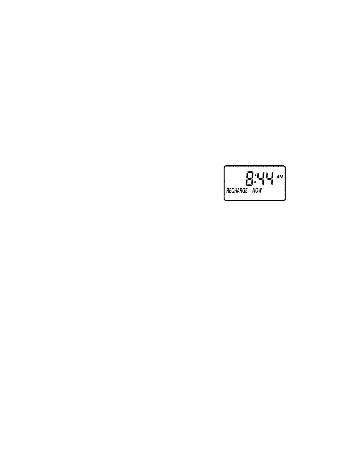
RECHARGE NOW
For times you expect to use
more water than usual, use the
RECHARGE NOW feature.
Press the RECHARGE button
and hold in for three seconds.
"RECHARGE NOW" begins to
flash in the display and a re
charge starts right away. You
will have filtered water when the
recharge is over in about two
hours.
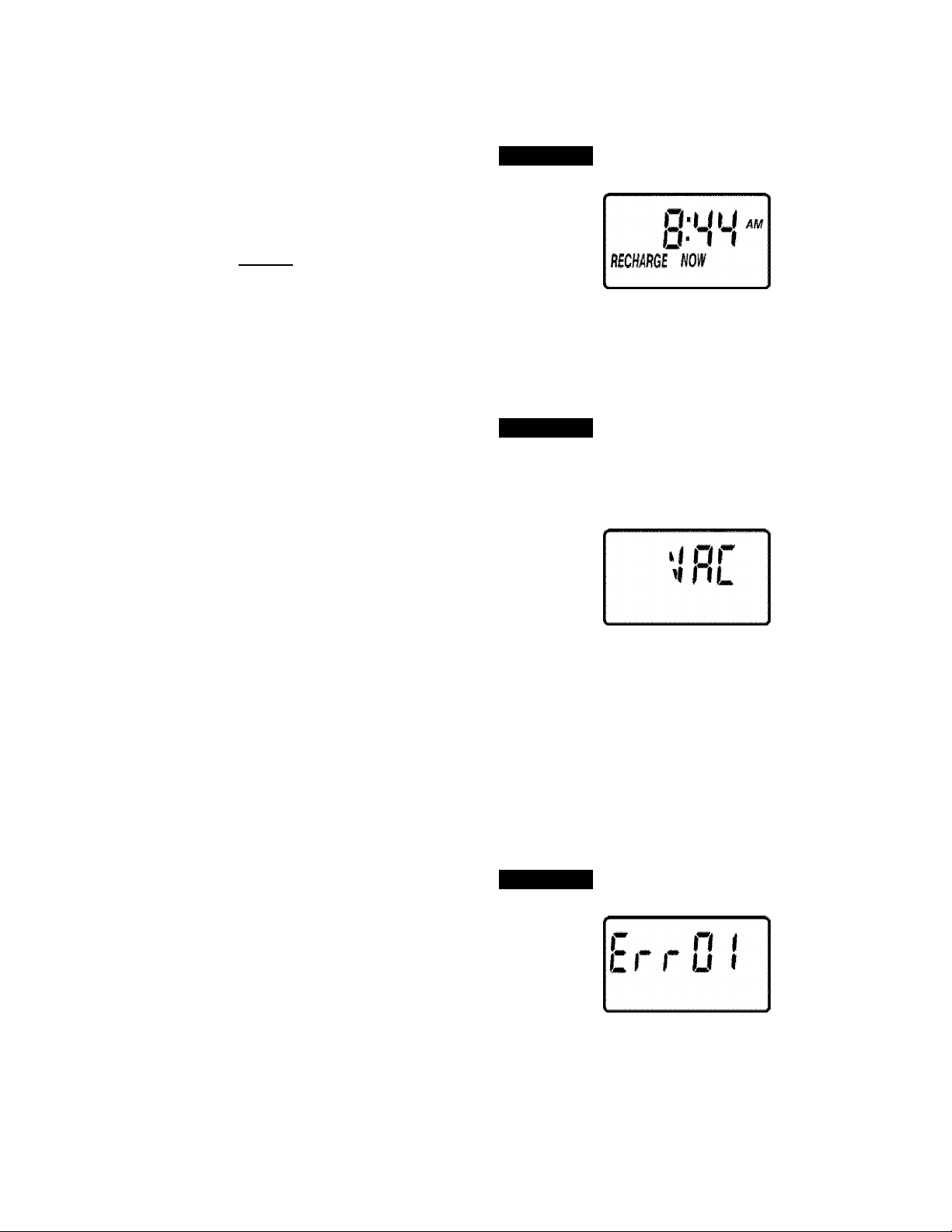
VACATION
The day you leave on vacation
or other long absence, press and
release (do not hold) the RE
CHARGE button. "VAC" begins
to flash in the display. The timer
will keep time, but the filter will
not recharge and waste water.
When you return, press and release the RECHAR
GE button again to return the filter to service, and
the correct time of day will show in the display.
Remember to do this or the filter will not recharge
and you will soon have tannins in your water sup
ply.
NOTE: While in VACATION, the filter will go
through a recharge if the RECHARGE NOW fea
ture is used.
To shut off the water supply to the filter, use the
plumbing bypass valve(s) . . . Figure 13 on page
4-1.
FIGURE 3
FIGURE 4
ERROR CODE
An error code could appear in the faceplate dis
play if a problem occurs in the filter electronics. If
you see and error code instead of the present time
of day, please call your local Sears Service Depart
ment for service.
Problems, Questions? Call 1-800-426-9345 Kenmore Water Line
FIGURE 5
2-1
Page 10
SECTION 2
HOW YOUR WATER FILTER WORKS
A. FACEPLATE TIMER FEATURES
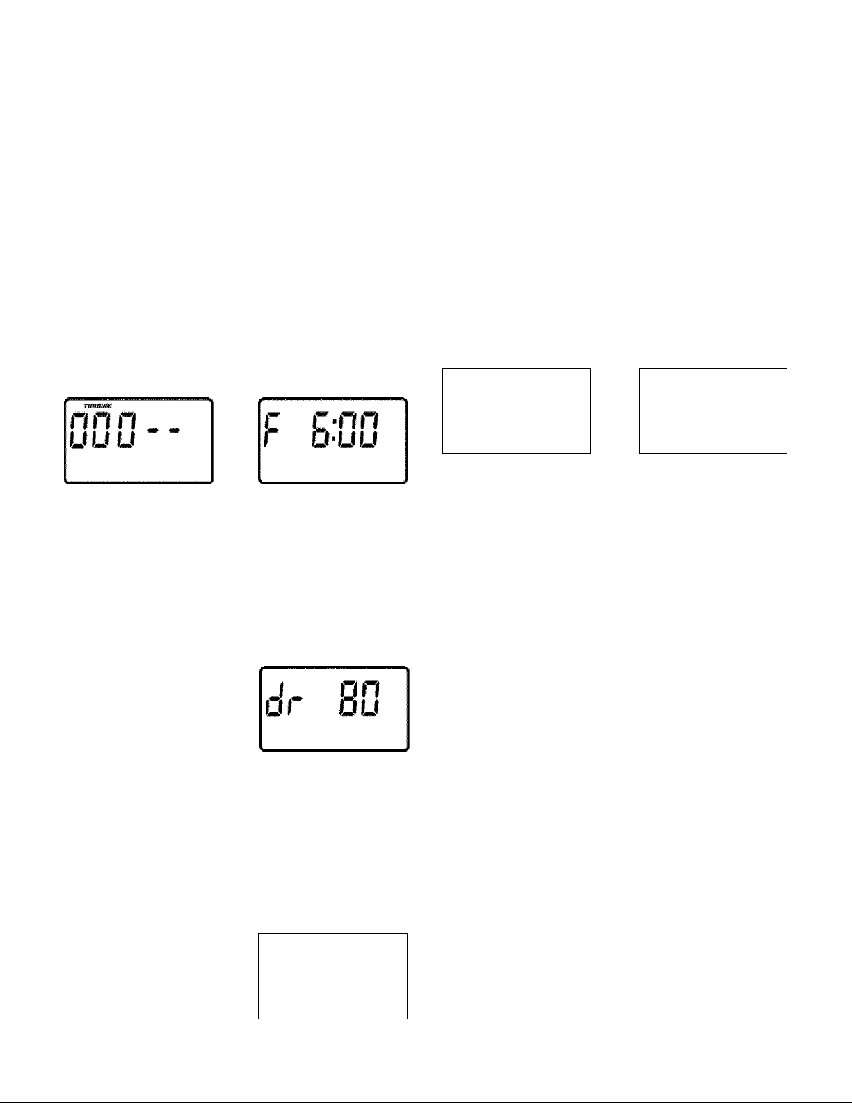
The default settings for fill (6:00 minutes), brine
draw (80 minutes), backwash (12 minutes) and
fast rinse (8 minutes) cycles of regeneration are
factory set for maximum performance of the filter.
Use the following procedures to check for correct
cycle times, or to change if desired.
trained technicians should change the time set
tings.
FILL
Press and hold the SELECT button until the dis
play shows "000- -", then press the SELECT but
ton once to display the Fill time screen.
This setting should stay at the 6:00 minute fill
time.
However, only
Using the UP or DOWN buttons, adjust the back
wash time from 0 minutes to 60 minutes.
ADJUSTABLE FAST RINSE
Press and hold the SELECT button until the dis
play shows "000--", then press the SELECT but
ton four times to advance to the Fast Rinse time
adjust screen.
тиШШё
ЛЛ Л _ _
uuu
Using the UP or DOWN buttons, adjust the fast
rinse time from 0 minutes to 60 minutes.
r П
t t 0
: Tfiff
ADJUSTABLE BRINE DRAW
Press and hold the SELECT button until the dis
play shows "000- -", then press the SELECT but
ton twice to advance to the Brine Draw time adjust
screen.
ППП
uuu
Using the UP or DOWN buttons, adjust the brine
draw time from 0 minutes to 255 minutes.
ADJUSTABLE BACKWASH
Press and hold the SELECT button until the dis
play shows "000- -", then press the SELECT but
ton three times to advance to the Backwash time
adjust screen.
Г1Л ri
uuu
1. 0
on
. (0
iC
Mi
TIMER "POWER-OUTAGE MEMORY"
If electrical power to the timer is interrupted, the
"memory" built into timer circuitry keeps time for
6 hours (minimum) or more. The display is blank
and the filter will not regenerate. When electrical
power comes on, one of two things will happen.
1. The present time of day will show steady,
meaning the timer has not lost time.
2. The display will show a time, but it will be
flashing. The timer memory did not keep the
time setting and must be reset (page 1-3). If
you do not reset the time, regenerations will
most likely be at the wrong time of day.
NOTE: The flashing display is to remind you to
reset the timer.
NOTE: If the filter was in a recharge when power
was lost, it will now finish the cycle.
2-2
Problems, Questions? Call 1-800-426-9345 Kenmore Water Line
Page 11

SECTION 2
HOW YOUR WATER FILTER WORKS
B. FILTERED WATER, SERVICE AND REGENERATION
IMPORTANT: Sears water filters are sometimes installed alone in the water system, but most often other
water treating equipment is needed. Always be sure to have your water tested by a qualified testing labo
ratory. If you need help, ask at your Sears store, or call the Kenmore Water Line, 1-800-426-9345.
TANNIN WATER
Water containing tannin has a yellowish cast (even
after softening and/or filtering). Tannin can be an
associated cause of yellow stains on washable fab
rics, china, and plumbing fixtures. Tannins (humic
acids) are harmless organics, caused by the water
passing through peaty soil and decaying vegeta
tion.
SERVICE
When the filter is providing filtered water, it is
called "Service". During service, unfiltered water
flows from the house main water pipe into the fil
ter. Inside the filter resin tank is a bed made up of
thousands of tiny, plastic resin beads. As unfil
tered tannin passes through the bed, each bead
attracts and holds the tannin particles. It is much
like a magnet attracting and holding metals. Water
without the tannin particles flows out of the filter.
FIGURE 6
SERVICE
WATER
IN
REGENERATION
FILL: Salt, dissolved in water is called brine. Brine
is needed to clean the tannin particles from the
resin beads. To make the brine, water flows into
the salt storage area during the fill stage as shown
below.
FIGURE 7
FILL
WATER
IN
Resin Bed
After a period of time the resin becomes coated
with tannin particles and it has to be cleaned. This
cleaning is called regeneration. Regeneration is
started at 12:00 AM (or other preselected time) by
the timer, and consists of five cycles: (1) TILT, (2)
BRINING, (3) BRINE RINSE, (4) BACKWASH, (5)
EAST RINSE.
Problems, Questions? Call 1-800-426-9345 Kenmore Water Line
BRINING: During brining, the brine travels from
the salt storage area, to the resin tank. Brine causes
the resin to release the tannin particles, and they
are carried to the drain.
The nozzle and venturi create the suction to move
the brine, maintaining a slow flow rate for maxi
mum cleaning.
2-3
Page 12

SECTION 2
HOW YOUR WATER FILTER WORKS
B. FILTERED WATER, SERVICE AND REGENERATION
BRINE RINSE: After a premeasured amount of
brine is used, the brine valve closes. Water flow
continues as during brining, except for the brine
draw. Tannin particles and brine are flushed from
the resin tank to the drain.
FIGURE 8
BRINING / BRINE RINSE
WATER
IN
BACKWASH: During backwash, water flows UP
through the resin tank at a fast rate to flush iron
minerals, dirt and sediments from the bed and to
the drain. The bed lifts and expands for maximum
cleaning.
FIGURE 9
BACKWASH
WATER
FAST RINSE: Backwash is followed by as fast flow
of water down through the resin tank (page 19).
The fast flow packs the resin bed and gets it ready
for return to service.
FIGURE 10
FAST RINSE
WATER
FILTERED
WATER OUT ^
AUTOMATIC BYPASS
IN
During the brining, brine rinse and backwash
cycles of regeneration, unfiltered water goes
through the filter valve and to the house pipes, if a
faucet is opened. However, you should not use
HOT water, if possible, because the water heater
will refill with unfiltered water.
resin bed lifted
and expanded
2-4
Problems, Questions? Call 1-800-426-9345 Kenmore Water Line
Page 13

SECTION 3
CARE OF YOUR FILTER
A. CHECKING THE SALT STORAGE LEVEL AND REFILLING
Brine (salt dissolved in water) is
needed for each and every re
generation. The water for mak
ing brine is metered into the salt
storage tank by the filter. How
ever, you must keep salt in the
tank.
WHEN TO REFITT WITH SAET:
Check the salt level a few weeks
after you install the filter and ev
ery week after that. Refill when
the storage tank is about 1/3
full. Never let the filter use all
the salt before refilling. Without
salt, you will soon have unfil
tered water.
B. BREAKING A SALT BRIDGE
Sometimes, a hard crust or salt
bridge forms in the salt storage
■
empty space forms between the water and salt. Then
salt will not dissolve in the water to make brine.
tank. It is usually caused by high
humidity or the wrong kind of
salt. When the salt bridges, an
Use nugget or pellet water softener salt only. Do
not use rock salts. They have dirt and sediments
that will cause maintenance problems. Fill the
tank from 1/2 to 3/4 fill. In humid areas where
salt bridging may be a problem, it is best to keep
the salt level lower and to refill more often.
CAUTION: WATER SOFTENING SALT WITH
IRON REMOVING ADDITIVES - Some salts
have an additive to help keep the resin bed clean.
THIS ADDITIVE WILL RUIN THE TANNIN
REMOVING RESIN ... SEE PAGE 4.
FIGURE 11
If the storage tank is full of salt, it is hard to tell if
you have a salt bridge. Salt is loose on top, but the
bridge is under it. The following is the best way to
check for a salt bridge.
Salt should be loose all the way to the bottom of
the tank. Take a broom handle, or like tool, and
CAREFULLY push it down into the salt, working
it up and down. If the tool strikes a hard object (be
sure it's not the tank bottom), it's most likely a salt
bridge. Carefully break the bridge with the tool.
Do not pound on the outside of the brine tank.
If the wrong kind of salt made the bridge, take it
out. Then fill (about 1/2 full) the tank with nugget
or pellet salt only.
3-1
Problems, Questions? Call 1-800-426-9345 Kenmore Water Line
Page 14

SECTION 3
CARE OF YOUR FILTER
C. CLEANING THE FILTER RESIN BED
To keep the tannin resin bed clean and working
efficiently, do the following at least once each
month.
Use one gallon of luke warm water (do not use hot
water) to fully dissolve 1 cup of soda ash. After
D. CLEANING THE NOZZLE AND VENTURI
A clean nozzle and venturi (Figure 12) is a must
for the filter to work right. This small unit moves
brine from the salt storage tank to the resin tank
during regeneration. If it becomes plugged with
sand, silt, dirt, etc., the filter will not work and
you will get unfiltered water.
Be sure the filter is in service cycle (no water pres
sure at nozzle and venturi), then turn off the cap
from the nozzle and venturi housing. Lift out the
screen support and screen, then the nozzle and
venturi. Wash and rinse the parts in warm water
until clean. If needed use a small brush to remove
iron or dirt. Also check and clean the gasket and
flow plug if dirty.
Carefully replace all parts in the correct order. Lu
bricate the o-ring seal with silicone grease or Vase
line and place in position. Install and tighten the
cap, BY HAND ONLY. DO NOT OVER TIGHTEN
AND BREAK THE CAP OR HOUSING.
It is recommended that you clean the nozzle and
venturi at least three times a year. Clean more
often if you notice a difference in water quality.
thoroughly stirred, pour the solution directly into
the brinewell (see key no. 25, page 6-2).
The solution will be drawn into and through the
resin bed during filter regenerations.
FIGURE 12
0-Ring
Screen
Support
Screen
Nozzle &
Venturi
* Gasket
'Flow Plug
Nozz. & Vent.
Housing
NOTE: Be sure holes in the
gasket align with the holes at
the bottom of the nozzle &
venturi housing.
•INSTALL \NIJH
NUMBERED SIDE UP,
CONCAVE SIDE DOWN
3-2
Problems, Questions? Call 1-800-426-9345 Kenmore Water Line
Page 15

SECTION 3
CARE OF YOUR FILTER
E. KEEP THE FILTER FROM FREEZING
If the filter is installed where it could freeze (sum
mer cabin, lake home, etc.) you must drain all wa
ter from it to stop possible damage caused by
freezing. To drain the filter-
1. Close the shutoff valve on the house main wa
ter pipe, near the water meter or pressure
tank.
2. Open a faucet in the filtered water pipes to
vent pressure in the filter.
3. Looking at Figure 13 on page 4-1, move the
stem in a single bypass valve to bypass. Close
the inlet and outlet valves in a three valve by
pass system, and open the bypass valve.
4. Unplug the transformer at the wall outlet.
5. Pull the holding clip to remove the drain fit
ting, with drain hose attached, from the valve.
DO NOT LOSE THE BEACK RUBBER EEOW
PLUG AND RETAINER.
6. Looking at page 11 in the installation manual,
remove the plastic clips and pull the adaptors
or bypass valve from the inlet and outlet.
7. Move the filter close to the floor drain. SLOW
LY and CAREFULLY (the filter is heavy) tip
the filter over so the valve inlet and outlet are
over the drain. DO NOT RFST THE FILTER
ON THE INLET AND OUTLET EITTINGS
OR THEY WILL BREAK.
8. Tip the bottom of the filter up a few inches
and hold until all water has drained. Leave
the filter laving like this until you are ready to
use it. Plug the inlet and outlet with rags to
keep dirt, bugs, etc. out.
3-3
Problems, Questions? Call 1-800-426-9345 Kenmore Water Line
Page 16

SECTION 3
CARE OF YOUR FILTER
F. BEFORE YOU CALL FOR SERVICE . . . HELPFUL HINTS CHECKLIST
PROBLEM CAUSE CORRECTION
NO FILTERED WATER No salt, or salt bridged, in storage tank. Add salt to storage tank, or break up salt
bridge, and use the RECHARGE NOW
feature, page 2-1.
FILTER RECHARGES, BUT FILTERED
WATER SOMETIMES CONTAINS
TANNINS
Plumbing bypass valve{s) in “bypass”
position.
Transformer unplugged at wall outlet,
power cable disconnected from electronic
board, fuse blown/circuit breaker popped,
or circuit switched off.
Timer in the vacation "VAC” position Press the VACATION button once to re
Timer not programmed for recharge. See page 1 -4 to program a recharge
An error code shows in the face plate dis
play.
Backwash flow washer plugged. Remove drain hose adaptor to clean, see
Drain hose plugged, kinked or bent. Straighten hose, or remove and clean.
Too few regenerations programmed.
Possible change in water conditions.
Using more water since timer was pro
grammed.
HOT water used while the filter is recharg
ing
Move stem in a single bypass valve to
SERVICE. In a three valve bypass, open
the inlet and outlet valves, close the by
pass valve.
Check for loss of power and correct. Re
set the time and use the RECHARGE
NOW feature, page 2-1. Also see “Elec
tric Power Outlet For Your Filter”, page 17
in the installation manual.
turn the filter to service, see page 2-1.
schedule.
See page 2-1.
pages 5-4 and 6-4.
See page 1 -4 to change recharge sche
dule.
See maximum limits, page 4-2.
See page 1 -4 to program additional re-
generation(s).
The water heater will refill with bypass iron
water. Avoid using water during re
charges.
Leaking faucet or toilet valve A small leak can waste hundreds of gal
lons of water in a few days. Fix plumbing
leaks, and always fully close faucets.
3-4
Problems, Questions? Call 1-800-426-9345 Kenmore Water Line
Page 17

SECTION 4
A. DIMENSIONS / SPECIFICATIONS
OTHER THINGS TO KNOW
FIGURE 13
I BYPASS VALVES
SINGLE-PLASTIC
PULL STEM
OUTWARD
SERVICE
Push
Inward
For
Bypass
3-VALVE
SERVICE
Close Bypass Valve
Open Inlet & Outlet Valves
BYPASS
Open Bypass Valve
Close Inlet & Outlet Valves
FOR
Bypass
Valve
Inlet
Valve
Nominal Resin Tank Size; 10” Diameter x 47” high
CLASSIFICATION OF FILTER; ...................................................
FILTER TYPE;
..............................................................................
TYPE OF RESIN; .........................................................................
..............................................
..............................................
..............................................
AMOUNT OF MINERAL:............................................................... .................................1,0 cu. ft.
Household
Tannin removal
Acrylic, strongly basic
macroporous anion
exchange
4-1
Problems, Questions? Call 1-800-426-9345 Kenmore Water Line
Page 18

SECTION 4
A. DIMENSIONS / SPECIFICATIONS
OTHER THINGS TO KNOW
Pretreatment Needed
For Higher Amounts
Supply Water Limits
Listed
MAX, WATER HARDENSS:...........................................................
MAX, CLEAR WATER IRON: ........................................................ 2 ppm
MAX, CHLORINE*: ........................................................................ 1 ppm Activated Iron Filter
MAX, TANNIN: ............................................................................... 3 ppm
MAX, pH: ........................................................................................ 8,0
MAX, NITRATES:
MAX, SUSPENDED SOLDS*:........................................................ 1,0 NTU
INLET WATER PRESSURE LIMITS:
MAX, INLET WATER TEMPERATURE:
MIN, INLET WATER FLOW:........................................................... 4 gal/min.
MIN, INLET AND OUTLET PIPE SIZE:.......................................... 3/4 inch
BAOKWASH FLOW RATE (at 35 psi inlet pressure):
MIN, SALT USAGE AT EACH REGENERATION:......................... 5 lbs
MIN, FREQUENCY OF REGENERATIONS:
...........................................................................
.............................................
.......................................
....................
................................
10 gpg
2 mg/L
20-125 psi
120T
1 gal/min.
every 2 days
Water Softener
Water Softener and/or
Iron Filter
CAPACITY RATING: ...................................................................... See Rating Decal on Filter
continuous
4-2
Problems, Questions? Call 1-800-426-9345 Kenmore Water Line
Page 19

SECTION 5 SERVICE TECH. INFORMATION
A. WIRING SCHEMATIC
IMPORTANT: KEEP THIS MANUAL WITH YOUR WATER FILTER. IF REPAIRS ARE NEEDED, THE SER
VICE TECHNICIAN MUST HAVE THE INFORMATION ON THE FOLLOWING PAGES.
5-1
Problems, Questions? Call 1-800-426-9345 Kenmore Water Line
Page 20

SECTION 5 SERVICE TECH. INFORMATION
B. TROUBLESHOOTING
ALWAYS MAKE THESE INITIAL CHECKS EIRST
1. Does the time display show the correct time of
day?
...If display is blank, check power source to the
filter.
...If time is flashing, power was off for over two
days. The filter resumes normal operation but re
charges occur at the wrong time.
2. Plumbing bypass valve(s) must be in SERVICE
position (see Eigure 13, page 4-1).
3. The inlet and outlet pipes must connect to the
filter inlet and outlet respectively.
4. Is the transformer plugged into a "live"
grounded wall outlet, and the power cable fas
tened securely?
5. The valve drain hose must be free of kinks and
sharp bends.
If you do not find the problem after making the
initial checks, do the MANUAL ADVANCE
DIAGNOSTICS on page NO TAG.
MANUAL INITIATED ELECTRONICS DIAGNOSTIC
1. To enter diagnostics, press and hold the SE
LECT button until (000- - ) shows in the display.
Use the RECHARGE button to manually advance
the valve into each cycle and check correct switch
operation.
While in this diagnostic screen, the following in
formation is available and may be beneficial tor
various reasons. This information is retained by
the computer from the first time electrical power is
applied to the face plate.
...Press the UP button to display the number of
days this face plate has had electrical power ap
plied.
...Press the DOWN button to display the number
of regenerations initiated by this face plate since
the model code number was entered.
2. Press the SELECT button and hold for 3 seconds
until the model code appears in the display.
C . Q-
2 * ПМ
The letter (P) and dash or dashes indicate position
switch operation. The letter shows if the switch is
closed. A dash shows when the switch is open.
SWITCH
DISPLAYS
- -
- P
VALVE CYCLE STATUS
valve in service, fill, brine draw,
backwash or fast rinse position
valve rotating from one position
to another
NOTE: If the face plate is left in a diagnostic display (or a flashing display when setting times or days
to recharge), preset time automatically returns if a button is not pressed within 4 minutes.
Problems, Questions? Call 1-800-426-9345 Kenmore Water Line
NOTE: For correct filter operation, the model code
must be S tAn.
To reset the code, press the UP or DOWN buttons
until the correct model code shows in the display.
3. Press the SELECT button to return the present
time display. If the code was changed, make AEL
the timer settings, page 1-3 and 1-4.
5-2
Page 21

SECTION 5 SERVICE TECH. INFORMATION
B. TROUBLESHOOTING
MANUAL ADVANCE DIAGNOSTICS
Use the following procedures to advance the filter
valve through the regeneration cycles to check op
eration.
Remove the top cover to observe cam and switch
operation during valve rotation.
DISPLAY MUST SHOW TIME AND DAY
1. Press and hold the RECHARGE button for 3
seconds until RECHARGE NOW flashes in the
display and the filter moves into the fill cycle.
...If the motor does not ruiy check the motor and
all wiring connections.
Check for fill water flow to the brine tank. If water
does not enter the tank, look for an obstructed
nozzle and venturi, fill flow plug or brine tubing.
2. After verifying fill, press the RECHARGE but
ton to move the valve into brining. A slow flow of
water to the drain will begin. Verify brine draw
from the brine tank by shining the flashlight into
the brinewell and observing a noticeable drop in
the liquid level.
If the unit does not draw brine, check for...
...dirty or defective nozzle and venturi
...nozzle and venturi not seated on the gasket, or
gasket defective
...restriction in valve drain, causing a back- pres
sure (bends, kinks, elevated too high, etc.),
...obstruction in brine valve or brine tubing
...inner valve failure (obstructed rotor disc, wave
washer defective, etc.)
NOTE: Be sure a salt bridge is not preventing con
tact of the water with salt.
3. Again press the RECHARGE button to move
the valve into backwash. Look for a fast flow of
water from the drain hose (see specifications, page
4-1).
...An obstructed flow indicates a plugged top dis
tributor, backwash flow plug, or drain hose.
Be sure household water pressure (well system) is
maintained at a minimum of 20 psi. Adjust the
pump switch upward, if needed.
4. Press the RECHARGE button to move the filter
into fast rinse. Again, look for a drain flow rate
about the same as backwash.
5. To return the filter to service, press the RE
CHARGE button once.
OTHER SERVICE
UNFILTERED WATER BYPASS (unfiltered water
"bleeds" into filtered water supply.
1. Missing or defective o-ring(s) at resin tank to
valve connection.
2. Defective rotor disc, seal or wave washer.
WATER LEAKS FROM DRAIN HOSE (during ser
vice)
1. Defective rotor disc, seal, or wave washer.
2. Defective o-ring on disc shaft.
AUTOMATIC ELECTRONIC DIAGNOSTICS
The face plate has a self diagnostic function for the
electrical systems (except input power). The face
CODE MOST LIKELY LEAST LIKELY
Err 01, Err 03
& Err 04
Err 05 faceplate
PROCEDURE FOR REMOVING ERROR CODE FROM FACEPLATE: 1. Unplug transformer
fect------3. Plug in transformer
the RECHARGE button for 3 seconds as an alternate way to clear an error code.
wiring harness or connection to position switch / switch / valve defect causing high torque /
motor inoperative
--------
4. Wait for 12 minutes. The error code will return if the defect was not corrected. Press and hold
plate monitors the electronic components and cir
cuits for correct operation. If a malfunction occurs,
an error code appears in the face plate display.
POSSIBLE DEFECT
-------------
2. Correct de
■ 5-3
Problems, Questions? Call 1-800-426-9345 Kenmore Water Line
Page 22

SECTION 5 SERVICE TECH. INFORMATION
C. ROTARY VALVE SERVICE
IMPORTANT: Before working on the valve, turn
off the water supply and disconnect from electrical
power.
To relieve pressure:
.. . THREE VAEVE BYPASS: Close the inlet and
open a filtered water faucet. Then close the outlet
valve and open the bypass valve.
.. . SEARS SPECIAE BYPASS: Slide the bypass
valve stem to bypass position. Loosen the three
hex head screws (see (g) in drawing) toward the
backside of the valve to allow pressure water to
bleed out (catch water with a rag).
DISASSEMBLY
To remove a part or group of parts, refer to the
valve drawing. A common screwdriver or nut
driver, Phillips screwdriver and pliers are the only
tools needed to completely disassemble.
SERVICING THE VALVE
Inspect all o- rings, seals and gaskets for wear or
defects.
Inspect the bottom surface of the rotor and disc for
scratches, chips or wear.
NOTE: If a replacement is needed, be sure to use
the current replacement part.
ASSEMBLY
Be sure all parts are in place and in the proper
position. Lubricate ALL o- rings, and seals with
FDA approved silicone grease. To install the rotor
seal, first place the seal into the valve groove,
round side down (see cross section). Apply a light
coating of silicone grease to the seal's crossing
ribs. Then carefully center the wear strip on the
seal, and push it downward onto the seal.
Install the nozzle and venturi seal and drain seal.
Assemble two o-rings and the wave washer onto
the rotor and disc. The center the rotor and disc, in
the valve body, on the rotor seal.
Lower the cover onto the valve body and rotor
shaft. Then install the cover holding screws.
Before tightening the screws, install the valve cam
and gear, then turn the rotor (clockwise only) to
service postion.
spacer
switch
motor plate
flow plug {back
wash and fast rinse
flow rate control)
rotor & disc
o-nng
rotor seal
drain seal
nozzle and
venturi seal
Tighten the screws using a criss-cross pattern. If a
torque wrench is available, torque to 30-40 inch
pounds.
Lubricate the gear on the motor, and the valve
cam gear with Molykote grease, or other high
quality gear lubricant.
Be sure to orient switch as shown, with lever to
ward the valve cam.
5-4
Problems, Questions? Call 1-800-426-9345 Kenmore Water Line
Page 23

SECTION 5 SERVICE TECH. INFORMATION
D. WATER FLOW THROUGH THE FILTER VALVE
SERVICE CYCLE
Unfiltered water enters the valve inlet port. Internal valve porting routes the water down and out
the top distributor, into the resin tank. Unfiltered water is filtered as it passes through the resin bed,
then enters the bottom distributor. Filtered water flows back into the valve and out the valve outlet,
to the house water pipes.
FILL CYCLE
VALVE CAM
POSITION
SWITCH
VENTUR
FILL FLOW
PLUG
FILL WATER'
(FILTERED)
VALVE OUTLET
(FILTERED
WATER)
ROTOR & DISC
VALVE INLET
'■ ’ (UNFÌLTERED WATER)
To begin a regeneration, the electronic timer energizes the circuit to the valve motor. The valve
motor rotates the rotor and disc and the valve cam until the position switch lever drops to open
the motor circuit, when the valve reaches FILL position. As the rotor and disc rotates, the port
opens for filtered water to fill through the venturi. Fill flow continues to the brine valve, and into
the salt storage tank. Filtered water is still available to the house lines.
5-5
Problems, Questions? Call 1-800-426-9345 Kenmore Water Line
Page 24

SECTION 5 SERVICE TECH. INFORMATION
D. WATER FLOW THROUGH THE FILTER VALVE
VALVE
OUTLET
(BYPASS UNFILTERED
WATER)
BRINING AND BRINE RINSE CYCLES
ROTOR & DISC
VENTURI
NOZZLÉ
BRINE
FROM SALT
STORAGE
TANK
DRAIN
VALVE INLET
(UNFILTERED WATER)
TOP
DISTRIBUTOR
POSITION
SWITCH
BOTTOM
After fill, timer / switch action allows the motor to turn the rotor and disc into BRINING position.
Water flow is directed to the nozzle. Suction, created by the nozzle and venturi, draws brine from
the salt storage tank and injects it into the resin bed via the bottom distributor. Flow continues out
the top distributor and to the drain. Unfiltered water is available at the valve outlet.
When the brine valve closes to end brine draw, water flow continues in the same directions to slowly
RINSE brine from the resin bed and to the drain.
BACKWASH CYCLE
ROTOR & DISC
FLOW PLUG
Timer / switch action again allows the motor to turn
the rotor & disc to place the valve in BACKWASH,
stopping water flow to the nozzle. Water is routed
down and out the bottom distributor, up through the
bed, and out the top distributor to the drain. The fast
flow (controlled by a flow plug in the drain fitting)
flushes dirt, sediments, deposits, remaining brine and
hardness to the drain.
VALVE
OUTLET
DRAIN
VALVE
INLET
TOP
DISTRIBUTOR
POSITION
.
___
RESIN ’
\ BOTTOM
DISTRIBUTOR
SWITCH
5-6
Problems, Questions? Call 1-800-426-9345 Kenmore Water Line
Page 25

SECTION 5 SERVICE TECH. INFORMATION
D. WATER FLOW THROUGH THE FILTER VALVE
FAST RINSE CYCLE
ROTOR & DISC
During FAST RINSE, the rotor & disc is positioned so water flow enters the resin tank through the
top distributor, and exits through the bottom distributor, to the drain.
The timer again energizes the motor to return the valve to service, and as the valve rotates, the
position switch lever drops to open the circuit. The valve remains positioned in service until the
timer initiates the next regeneration.
5-7
Problems, Questions? Call 1-800-426-9345 Kenmore Water Line
Page 26

SECTION 6
Kenmore MODEL NO. 625.348261
REPAIR PARTS
39
19
20
\
21
6-1
Problems, Questions? Call 1-800-426-9345 Kenmore Water Line
Page 27

SECTION 6
Kenmore MODEL NO. 625.348261
REPAIR PARTS
KEY
NO.
10 7146734 Bottom Cover
11 7176292 Clamp Section (2 req’d.)
12 7088033 Clamp Retainer (2 req’d.)
13 7170296 0-ring, 2-7/8” x 3-1/4”
14 7170254 0-ring, 13/16” X 1-1/16”
15 7170270 0-ring, 2-3/4” X 3”
16 7112963 0-ring Kit
17 7077870 Top Distributor
18 7105047 Repl. Distributor (bottom)
19 7092202 Resin Tank, 10” x 47”
20 7148338 Resin, 1 cu ft
21 7026196 Base
PART
NO.
1 7275907 Transformer
2 7259927 Wire Harness
3 7285677 Rep’l Faceplate Timer
4 0900300 Screw, #4 X 1/4” (2 req’d.)
5 7128566 Power Cable Wire Harness
6 7144449 Cover, Controller
7 7103972 Screw, #8 X 7/16” (4 req’d.)
8 0900291 Screw, #18 X 3/8” (2 req’d.)
9 7288120 Bracket
DESCRIPTION
KEY
NO.
22 7180437 Cover, Brine Tank
23 0500283 Brinewell Cover
24 7082150 Wing nut
25 7100819 Brinewell
26 7003847 O-rIng
27 7148875 Screw, 1/4-20 x 5/8” long
28 9003500 Grommet ■
29 1103200 Hose Adaptor ■
30 0900431 Hose Clamp ■
31 7112612 Brine Tank
32 7116488 Brine Valve Assembly
33 7095470 Brine Tube
34 7113016 Tubing Assembly
35 7131365 Screen
36 7080653 Clip
37 7113008 Float, Stem & Guide Assembly
38 1205500 Clip
39 7092210 Shroud Kit
♦ 7123613 Grease for O-rings
♦ 7139999 Drain Tubing
♦ 7282572 Owners Manual
♦ 7146611 Installation Manual
■ included on small parts skin-pack
♦ not illustrated
PART
NO.
DESCRIPTION
6-2
Problems, Questions? Call 1-800-426-9345 Kenmore Water Line
Page 28

SECTION 6
Kenmore MODEL NO. 625.348261
REPAIR PARTS
6-3
Problems, Questions? Call 1-800-426-9345 Kenmore Water Line
Page 29

SECTION 6
Kenmore MODEL NO. 625.348261
REPAIR PARTS
KEY
NO.
10 7170262 O-ring Seal, 1 -1/8 in. x 1 -3/8 in.
11 7167659 Screen Support
12 7146043 Screen
13 7187772 Nozzle & Venturi, with Gasket
14 7084607 Flow Plug (.15 gpm)
15 7095030 Cone Screen
16 1148800 Fill Flow Plug (.3gpm)
17 1202600 Nut-Ferrule
18 7081104 Nozzle & Venturi Housing
19 7081201 Retainer
20 7170319 O-ring Seal, 1/4 in. x 3/8 in. (2 req’d)
21 7082053 Valve Body
22 7129889 Spring
23 7092642 Plug (Drain Seal)
24 7081764 Seal (Nozzle & Venturi)
PART
NO.
1 7070412 Screw, #4 - 24 X 1 -1/8 in.
2 7117816 Spacer
3 7030713 Switch
4 7077472 Expansion Pin
5 7074123 Screw, #10 14 X 2 in. {5 req'd)
6 7085263 Valve Cover
7 7082087 Wave Washer
8 7199232 Rotor & Disc
9 7199729 Cap
7204362 Gasket only
-
- 7137507 Nozzle & Venturi Assembly {includes key
nos. 9 - 16 & 18)
DESCRIPTION
KEY
NO.
25 7170204 O-ring Seal, 3/8 in. x 9/16 in.
26 7134224 Rotor Seal
27 7170246 O-ring Seal, 3-3/8 in. x 3-5/8 in.
28 7170212 O-ring Seal, 3/4 in. x 15/16 in.
29 7170238 O-ring Seal, 7/16 in. x 5/8 in.
30 7129716 Seal Kit (Includes Key Nos. 24 - 29)
31 0900431 Hose Olamp
32 7024160 Drain Hose Adaptor
33 7170327 O-ring Seal, 5/8 in. x 13/16 in.
34 0501226 Flow Plug, Bkw. and F. Rinse (.9 gpm)
35 7142942 Clip
36 7284964 Cam and Gear
37 0503288 Bearing
38 7288112 Motor Plate
39 0900857 Screw, #6 - 20 x 3/8 in. (2 req’d)
40 7285936 Motor - Includes Key No. 41
41 7131755 Screw, #6 - 20 X 7/8 in. (2 req’d)
42 0507369 Installation Nut (2 req’d) ■
43 0507615 Installation Tube (2 req’d) ■
44 7170335 Washer (2 req’d) ■
45 7116713 Clip (2 req’d) ■
46 7248706 Ground Clamp Kit ■
47 7129871 Bypass Valve
included on small parts skin-pack
PART
NO.
DESCRIPTION
6-4
Problems, Questions? Call 1-800-426-9345 Kenmore Water Line
Page 30

SECTION 6
REPAIR PARTS
NOTES
6-5
Problems, Questions? Call 1-800-426-9345 Kenmore Water Line
Page 31

SECTION 6
REPAIR PARTS
NOTES
6-6
Problems, Questions? Call 1-800-426-9345 Kenmore Water Line
Page 32

Get it fixed, at your home or ours!
Yoyr Home
For repair-in your home-of all major brand appliances,
lawn and garden equipment, or heating and cooling systems,
no matter who made it, no matter who sold it!
For the replacement parts, accessories and
owner’s manuals that you need to do-it-yourself.
For Sears professional installation of honme appliances
and items like garage door openers and water heaters.
1 -800-4-WIY-HOIiE® (1 -800-469-46i3)
Call anytime, day or night (U.S.A. and Canada)
www.sears.com
www.sears.ca
Oyr Home
For repair of carry-in items like vacuums, lawn equipment,
and electronics, call or go on-line for the location of your nearest
Sears Parts & Repair Center.
1-800-488-1222
Call anytime, day or night (U.SA only)
www.sears.com
To purchase a protection agreement (U.S.A.)
or maintenance agreement (Canada) on a product serviced by Sears:
1-800-827-6655 (U S A ) 1-800-361-6665 (Canada)
Para pedir servicio de reparación
a domicilio, y para ordenar piezas:
1-888-SU-HOGAR""
(1-888-784-6427)
Au Canada pour service en français:
1-800-LE-FOYER“^
(1-800-533-6937)
www.sears.ca
® Registered Trademark / Trademaris t * Service Mark of Seare, Roebuck and Co.
® Marca Regislrada / Marca de Fábrica / Marca de Servicio de Sears. Roebuck and Co.
Manjue de commerce / * Marque déposée de Sears, Roebuck and Co. Í Sears, Roebuck and Co.
 Loading...