

Kenmore 625.347001 User Manual
OWNER’S
MANUAL
MODEL NO.
625.347001
Caution:
Read and Follow
All Safety Rules and
Operating Instructions
Before First Use of
This Product.
Reverse Osmosis
Drinking Water System
If you have questions when
installing, operating or
maintaining your reverse
osmosis system, call this
toll--free number...
1--800--426--9345
SAVE THIS MANUAL
PRINTED IN U.S.A.
u Warranty
u How To Install
u How It Works
u Care Of
u Repair Parts
1
Sears, Roebuck and Co., Hoffman Estates, IL 60179 U. S. A.

-- WARRANTY --
FULL WARRANTY ON REVERSE OSMOSIS DRINKING WATER SYSTEM
(except filter cartridges and R. O. membrane)
For one year from thedate of purchase, when theReverse OsmosisDrinking Water System is installed
and maintained in accordance with our instructions, Sears willrepair,freeof charge, defects in material
and workmanship, except filter cartridges and the R. O. membrane.
TO OBTAIN WARRANTY SERVICE, SIMPLY CONTACT THE NEAREST SEARS SERVICE CENTER
THROUGHOUT THE UNITED STATES. This warranty applies only while this product is in use in the
United States.
Thiswarrantygivesyouspecificlegalrights,andyou mayhaveotherrightswhichvaryfromstate tostate.
Sears, Roebuck and Co., D/817 WA, Hoffman Estates, IL 60179
SEARS INSTALLATION POLICY
All installation laborarranged by Sears shall be performed in a neat, workmanlike manner in accordance with generally accepted trade practices. Further, allinstallations shall complywithall local laws,
codes, regulations, and ordinances. Customer shall
also be protected, during installation, by insurance
relating to Property Damage, Workman’s Compensation and Public Liability.
-- SAFETY GUIDES --
B Read all steps, guides and rules carefully before
installing and using your reverse osmosis system.
Follow all steps exactly to correctly install. Reading
this manual will also help you to getall the benefits
from the reverse osmosis system.
B Donotattempt to usethisproductto make safe
drinkingwaterfromnon-potablewatersources.Do
notuse thesystemon microbiologicallyunsafewater, or water of unknown quality.
SEARS INSTALLATION W ARRANTY
In addition to any warranty extended to you on the
Sears merchandise involved, which warranty becomeseffectivethedate themerchandiseis installed,
should the workmanship of any Sears arranged
installation prove faulty within one year, Sears will,
upon notice from you, cause such faults to be corrected at no additional cost to you.
your house water pressure is over the maximum,
install apressurereducingvalve in the watersupply
pipe to the reverse osmosis system.
B Do not install the reverse osmosis system outside,orinextremehot orcoldtemperatures.Temperatureofthewater supplytothereverse osmosis system must bebetween 40_F and 100_F.Do notinstall
on hot water.
B Checkwithyourlocalpublicworksdepartment
for plumbing and sanitation codes. You must follow their guides as you install the system. Follow
your local codes if they differ with guides in this
manual.
B Thereverseosmosis systemworksonwaterpressures of 40 psi (minimum) to 125 psi (maximum). If
B Read the other limits (pH, hardness, etc.) in the
specifications and be sure your water supply conforms. Also see “Water Supply” on page 3.
B The reverse osmosis membrane contains a preservative forstorageandshipment. Besureto purge
as instructed on page 9 beforeusingproductwater.
2
-- TABLE OF CONTENTS --
Where To Install the RO System . .. . . . .. 4
Tools and Materials Needed . . . . .. . . . .. 4
Installation Steps . . . . .. . . . .. . . . .. . . . . 5-9
Cold Water Supply Saddle Valve . . . . . 5
Drain Adapter . . . .. . . . .. . . . .. . . . .. . 6
Faucet . .. . . . .. . . . .. . . . .. . . . .. . . . .. 6-7
RO Assembly .. . . . .. . . . .. . . . .. . . . .. 7
Storage Tank, Tubing Connections .. . . 8
Installation Steps - continued
Sanitizing, Pressure Test, Purging . .. . 9
How the RO System Works .. . . . .. . . . . 10
Care of RO System . . .. . . . .. . . . .. . . . .. 11-14
Dimensions, Specifications . . .. . . . .. . . . 15
Repair Parts . . . .. . . . .. . . . .. . . . .. . . . .. 16-17
Remote Installation Locations . . .. . . . .. 18
-- WHAT YOUR REVERSE OSMOSIS SYSTEM WILL DO --
Your Reverse Osmosis (RO) DrinkingWaterSystem
is a water treatment unit. It uses household water
pressure to reverse anatural physical process called
osmosis. Water, under pressure, is forced through a
semi-permeable membrane where minerals and impuritiesarefilteredout.Clean drinkingwatergoesto
the faucet orstorage, while minerals and impurities
aresenttothedrain withROwastewater.Theminerals and impurities are measured in water as totaldis-
solved solids (TDS).
The system includes replaceable pre and postfilter
sediment-carbon cartridges. The prefilter removes
sand, silt, dirt, rust particles, other sediments, and
chlorinefromthewatersupplybeforeitcanenterthe
RO membrane. The postfilter removes any tastes
and/or odors that may remain in the water, after
passing through the RO membrane, and just before
going to the RO faucet. To prevent water waste, an
automaticshutoffvalve closes when the ROfaucetis
closed and the storage tank is full.
Yourreverseosmosis system gives youacontinuous
supply of sparkling clear, delicious water for drinking, cooking and other uses. Foods will look and
tastebettertoo. Havinghigh qualityROproductwater at your fingertips eliminates the need to buy
bottled water.The storage tank holds over 2 gallons
of RO product water for your needs.
-- BEFORE YOU BEGIN TO INSTALL THE RO SYSTEM --
Check Your WaterSupply: The cold water supply to
the RO system must be within certain quality limits.
Seethespecificationtableonpage15.Ifsupplywater
is not within limits, the RO system can not make
product water as it should and reduced RO membrane life will result.
Trained salespeople at Sears can arrange for a free
wateranalysis. The analysis will tell you if otherwater supply treatment is needed before going to the
RO system.
CAUTION:Chlorinein the waterwill destroythe
ROmembrane.Most cities add chlorinetothewa-
ter supply to kill bacteria. The prefilter removes
chlorineupto thelimits shownin thespecifications
before it enters the RO membrane. It is important
to replace the prefilter cartridge at least every 6
months. See the RO care guide on page 14.
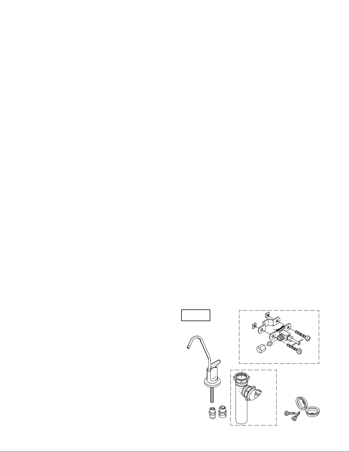
Check Parts Included: Unpack the carton and remove the RO system. In addition to the assembled
RO and the storage tank, the system includes the
parts illustrated below, a separate length of tubing,
and this manual.
FIG. 1
RO PRODUCT
WATER FAUCET
WATER SUPPLY SADDLE VALVE
DRAIN
ADAPTER
TUBING
ADAPTERS
HANGER
WASHERS &
SCREWS
3
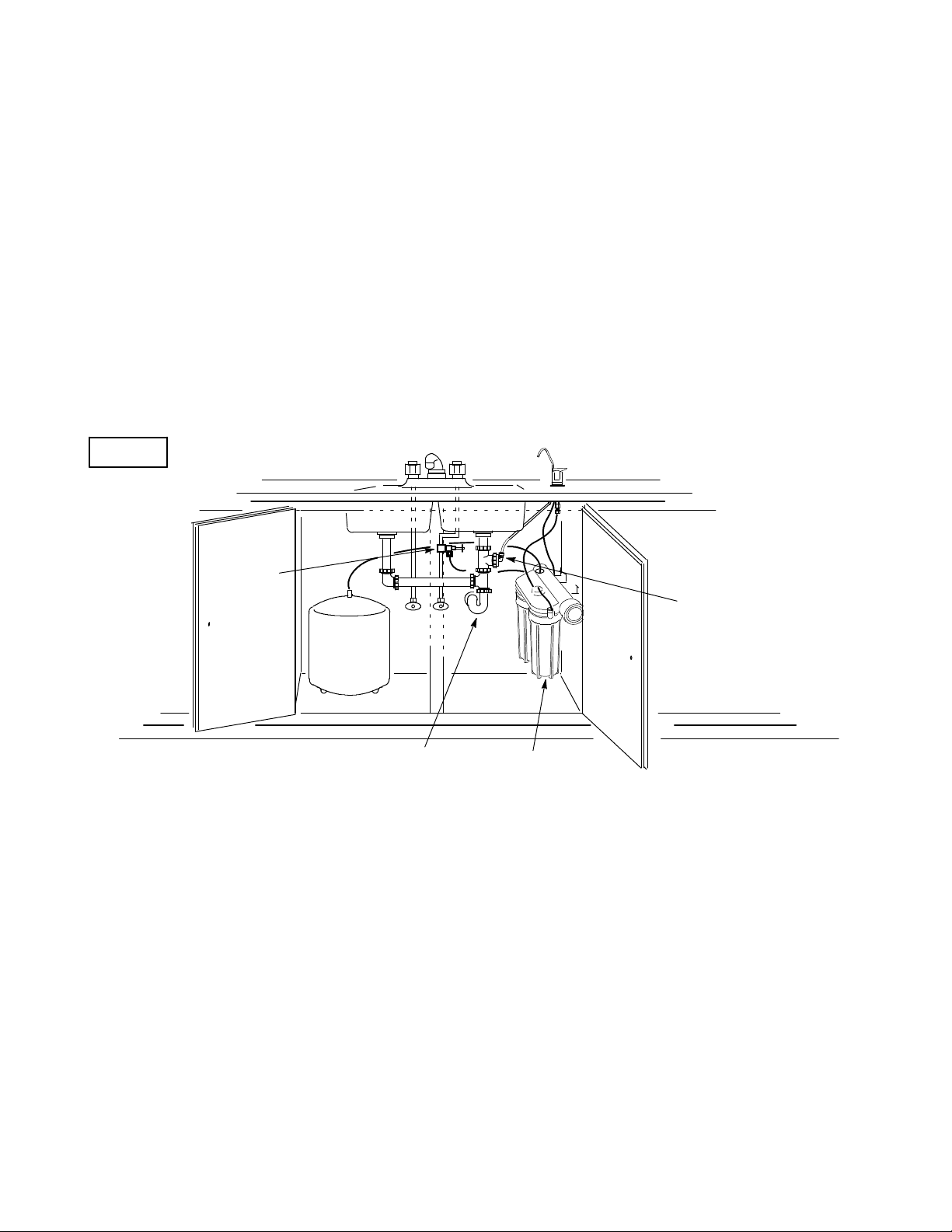
-- WHERE TO INSTALL THE RO SYSTEM --
The RO assembly and storage tank is designed for
installation under thesink, usually in the kitchen or
bathroom. The RO assembly mounts on a wall surface,or canlay onthe cabinetfloornexttothestorage
tank.Hanger washersandwoodscrewsareincluded
for cabinet wall mounting. The RO product water
faucet installs on the sink, oron the countertop next
to the sink (pages 6 and 7).
Note: Tubing lengths allow for the removal of the
assembly fromthehanger washers for servicing. If
tubing lengths are shortened for neater appearance, it maybe necessary to keepthe assembly on
the hanger washers for service.
YoucanalsolocatetheROassemblyandstoragetank
in any remote location from the faucet, observing
FIG. 2
cold water
supply
safety guides on page2.Youdo need a nearby water
source and drain point (see page 18).
Water Supply: To provide supply water to the RO
system inlet, a saddle valve is included to install
(wherecodes permit) onacold water pipe,page5.Provideotherpipefittingsfortubingconnection,astypically shown on page 5, where saddle valves are not
allowed.
Drain Point: A suitable drain point is needed for reject water from the RO membrane. A floor drain,
laundry tub, standpipe, sump, etc., is preferred, as
shown in the remote locations drawing, page 18. A
sinkp-trapdrainadaptoris includedtoinstallwhere
codes permit, as an optional drain point (page 6).
RO product
water faucet
COLDHOT
Storage
Tank
sink drain
p--- trap
-- TOOLS AND MATERIALS NEEDED --
" adjustable wrench, standard pliers, and larger
adjustable jaw pliers or pipewrench to fit sinkdrain
" slotted and Phillips head screwdrivers
" plumbers putty
" pipe joint compound(thread seal)orTeflontape,
approved for use on potable water supplies
-- 6 STEPS TO INSTALL --
STEP1: - Install ColdWater SupplySaddleValve,or
other fittings - page 5
STEP 2: - Install Drain Adapter - page 6
STEP 3: - Install Faucet - pages 6 and 7
drain adapter
RO Assembly
" hand or battery powered drill with 1/8” bit (if
needed for the cold water supply valve, page 5)
" electricdrilland bits, if hole is needed for theRO
faucet, page 6 and 7
STEP 4: - Install RO Assembly - page 7
STEP5: - InstallStorageTank,MakeRemainingTub-
ing Connections - page 8
STEP 6: - Sanitizing, Pressure Testing, Purging -
page 9
4
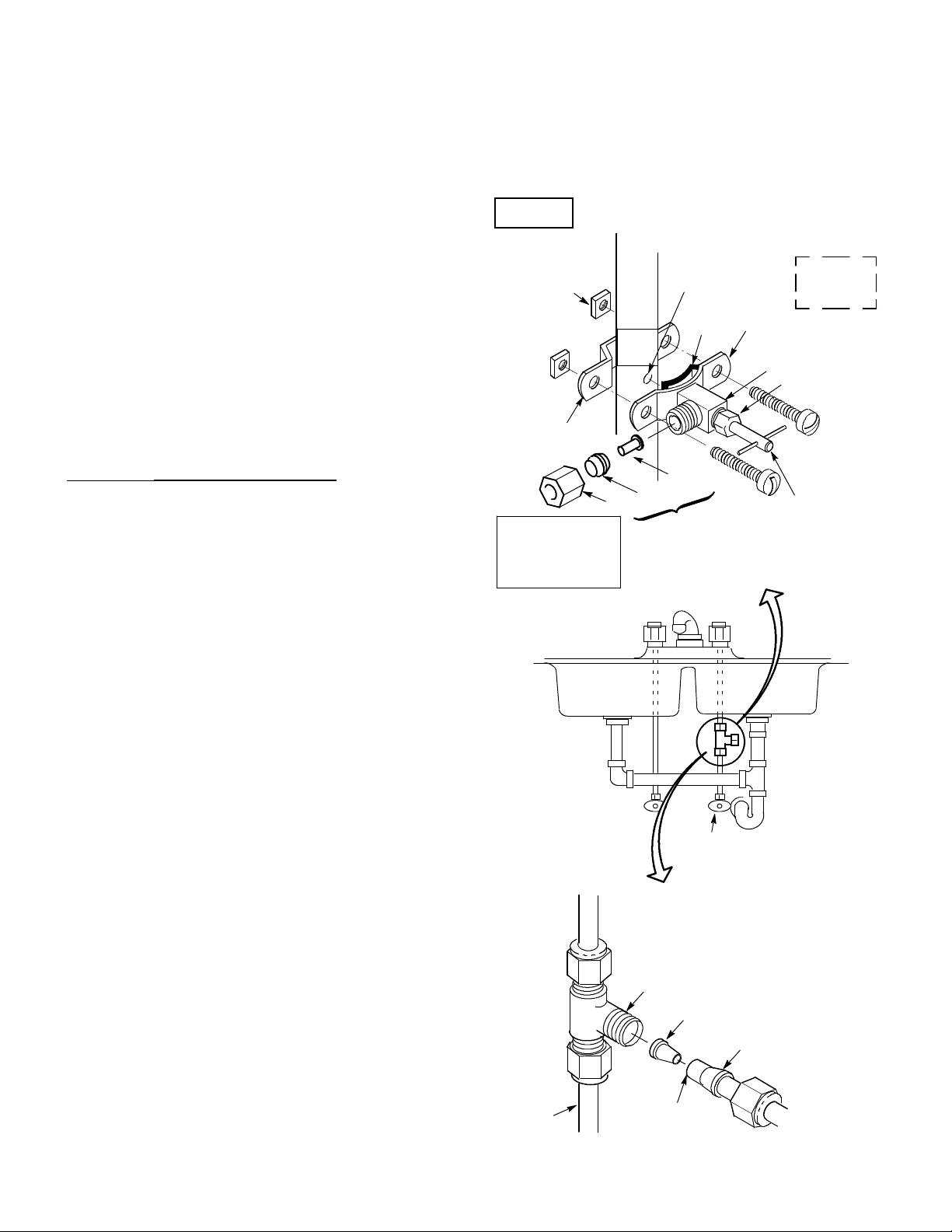
-- STEP 1: INSTALL COLD WATER SUPPLY SADDLE VALVE --
Checkandcomply with localplumbingcodes as you plan,theninstallacold feed (supply) water fitting. The
fitting must provide a leak-tight connection to theRO 1/4” tubing (see FIG. 8,page 8).A typicalconnection,
using theincludedsaddlevalveisshown inFIG.3 -A below.An optional connection, using standardplumbing fittings (not included), is shown in B.
Note:Codesin thestate ofMassachusettsrequireinstallation by a licensed plumber, and do not permit the use
of the saddle valve. For installation, use plumbing
code 248-CMR of the Commonwealth of Massachusetts.
A. SADDLE VALVE
Note: This valvehas a cutting pinand will pierce a
holeincoppertubingorplasticpipe.Ifinstallingon
ironpipe,youhavetodrilla1/8” holeforthepiercing pin. Read the following danger note and be
suretoturnoffwaterto thepipeandtodrainwater
from it before drilling.
DANGER(if drilling metalpipe):To protectyour-
selffromserious injuryorfatal shock,use abattery
powered hand drill only to make the hole. Do not
use an electric drill.
1.Closethehousemainwatershutoffvalveandopen
faucets to drain water from the sink cold water pipe.
2. Observing above note and caution, drill the 1/8”
diameter hole in iron pipe.
FIG. 3
nut (2) --- not req’d
with all types of
clamp Z
clamp Z
See note on codes
in the state of
Massachusetts,
above left.
A. WATER SUPPLY CONNECTION
(using included saddle valve)
nut
pre--- drill
1/8” hole
for iron pipe
seal
insert
ferrule
use to connect
tubing, step 2,
on page 8
clamp X
Checklocal
codes for
approval
valve
handle
3. Looking at figure 3A, turn the valve into clamp X
and tighten (maybe already assembled). Turn the
valve handle all the way out.
4. Place the seal on the inside of clamp X as shown.
Be sure the cuttingpindoesnotstickoutbeyondthe
seal.
5.Placeclamp XandZ aroundthe pipeand securein
place with 2 screws. If you predrilled a 1/8” hole,
align the cutting pin with it. Tighten both screws
evenly, but do not overtighten. Clamp Z will either
have threaded screw holes, or 2 nuts are included.
6. Carefully turn the handle inward to pierce a hole
in the copper or plastic pipe.
B. OPTIONAL PIPE FITTINGS (compression type
shown)
Note: Be sure to turn off the water supply and open
a low faucet to drain the pipe.
Complying with plumbing codes, install a fittingon
thekitchen coldwater pipeto adapt1/4” ODtubing.
A typical connection is shown in figure 3B. If
threaded fittings are used, be sure to use pipe joint
compound or Teflon tape on outside threads.
cold
water
pipe
cold water
shutoff
B. WATER SUPPLY
TYPICAL CONNECTION
(using compression fitting)
-- parts not included --
1/4” compression
fitting
insert
ferrule
1/4” tubing to
RO inlet (see step
2, on page 8)
5
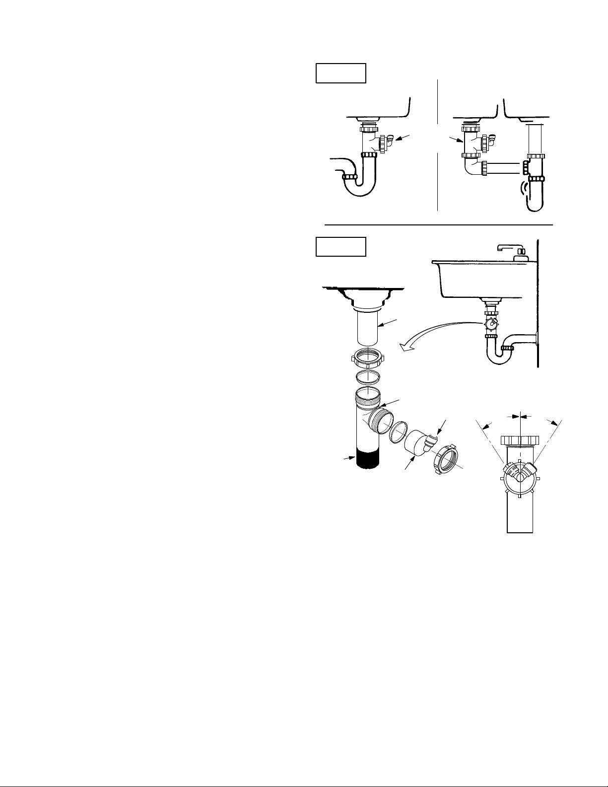
-- STEP 2: INSTALL DRAIN ADAPTER --
J Note: Runningthe drain tubing directly to a floor
drain, sump, standpipe, laundry tub,etc., as shown
on page 18, is preferred. However, if that is notpossible or practical,the included drain adapter installs
in the sink drain pipe, always above or ahead ofthe
p-trap (FIG. 4). Be sure to comply with your local
plumbing codes. Other drain pipe fittings, in addition to the adapter, may be needed.
J The drain adapter fits 1-1/2” sink drain pipe.
J Theadapterinstallsdirectlyontothe sinktailpiece
as typically shown in FIG. 4 and 5.
J Locateso draintubing fromthefaucet(installed in
step 1, page 8) makes a straight run to the adapter,
without dips, loops, low spots or kinks.
Note: Consult a plumber if you are not familiar
with plumbing procedures.
1. Use a ferrule and nut to assemble the drain tubing
connectortothe drain adapter(FIG.5).Turn theconnectorto about45_ fromthe12:00position, as shown
(to 10:00 or 2:00 position as needed).Tighten the nut
securely.
FIG. 4
A B
drain
adapter
FIG. 5
sink tailpiece
2. Carefully disassemble the sink drain pipe and
clean the tailpiece to assure a leak-tight fit.
3. Install the drain adapter onto the sink tailpiece,
using a ferrule and nut. Snug the nut, but do not
tighten.
Note: If needed,to make fit, you cancut toshorten
the unthreaded end of the adapter. Do not cuttoo
shortsotheadapterwillmakealeak-tightsealwith
the connecting fitting.
4.Assemble thep-trap tothe drainadapter,andother drain pipe fittings as required (check codes) to
complete the drain run.
5.Tightenallconnections,butdonotovertightenand
break plastic fittings.
-- STEP 3: INSTALL FAUCET --
A. PREPARE MOUNTING HOLE
1. Select 1 of the following places for the faucet. Be
sure it will fit flat against the surface, and there is
space underneath for tubing (see FIG. 8, page 8).
' Use an existing sink top hole for a spray hose or
other faucet. A 1”to 1-1/4” diameter hole isneed-
ed.
' Drill a new hole in the countertop next to the
sink.
' Drill a new hole in the sink top.
nut
ferrule
drain adapter
black
cut, if
needed
ferrule
drain tubing
connector
collet
nut
45_
45_
2:0010:00
CAUTION: To avoid damaging a sink beyond repair, consult a qualified plumber or installer for
guides to drill holes in porcelain or stainless steel.
2. If drilling is needed, make the 1” to 1-1/4”diameter hole.
3.Place plumbersputtyaroundthe drilledhole (FIG.
6) to prevent water leakage around the base of the
faucet.
6
 Loading...