

Page 1
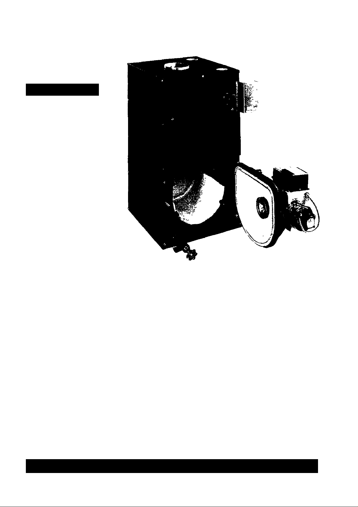
KenmatG
Owner’s Manual
MODEL NO.
3EW.65
3EW.75
3EW1.00
4EW.90
4EW1.25
4EW1.50
5EW1.20
5EW1.75
5EW2.00
CAUTION
Read all instructions
carefully before
starting the installation.
Save this manual
for reference.
Oil-Fired
Hot Water
Boiier
• Installation
• Operation
• Repair Parts
WARNING: litipropir iri--’,l ilinli.in nt ulkr.iiion i-ill Ljr
111 Iili|> n.Jdi - L.ili ruLJ .d iri|urv or ilurniCJi hU;k'T lO IMi',
di. mil ii ri'i . li i.inri I Ft .iiJditi' iiLil infcjirtinli. , ijfiMjll (.iimlilici I
III .l.nli' r r Jh t |[ |, III I ,r [ill Ull 'IlLl
Sears, Roebuck and Co., Hoffman Estates, fL 60179 U.S.A.
PRINTED IN US A
FOFIM 65^ IM 1!.
Page 2

Warranty
KENNMORE CAST IRON BOILERS
FULL ONE YEAR WARRANTY ON HOT WATER AND GAS STEAM CAST IRON BOILERS
For one (1) year from the date of Installation, when this boiler Is Installed and maintained in accordance
with our instructions. Sears will repair defects in material or workmanship in the boiler, free of charge.
LIMITED 12 YEAR WARRANTY ON STEAM CAST IRON BOILERS
Affer one (1) year and through twelve (12) years from the date of installation. Sears will furnish a replacement
heat exchanger, if the heat exchanger in the boiler is defective. YOU PAY FOR LABOR.
LIMITED 20 YEAR WARRANTY ON HOT WATER CAST IRON BOILERS
After one (1) year and through twenty (20) years from the date of installation, Sears will furnish a replacement
heat exchanger if the heat exchanger in the boiler is defective. YOU PAY FOR LABOR.
SEARS INSTALLATION WARRANTY
in addition to any \«arranty extended to you on the Sears merchandise inwived, which warranty becomes
effective the date the merchandise is installed, should the workmanship of any Sears arranged installation
prove faulty within one year. Sears will, upon notice from you, cause such faults to be corrected at
no additional cost to you.
FOR WARRANTY SERVICE, SIMPLY CONTACT THE NEAREST SEARS STORE OR SERVICE
CENTER THROUGHOUT THE UNITED STATES. This warranty gives you specific legal rights, and
you may also have other rights which vary from state to state.
mmmmmmmmmmmmmmmmmmmmmmimmmmmmm
IMPORTANT
The following are the responsibilities of the user and are
not covered by the Warranty.
1. Filter clearing or replacement.
2. Damage to unit or unsatisfactory operation due to improper
cleaning or use of unit in corrosive atmosphere.
3- Damage to unit or unsatisfactory operation due to blown
fuses or inadequate or interrupted electrical protective
devices.
4, Damage to unit caused by the use of components or other
accessories not compatible with the unit.
If the unit IS removed from the place it was originally
installed, this Warranty becomes void.
Damage to the unit caused by accident, abuse, negligence,
misuse, riot, fire, flood, or acts of God.
SEARS ROEBUCK AND COMPANY
D/817WA
Hoffman Estates, IL 60179
Page 3
INTRODUCTION
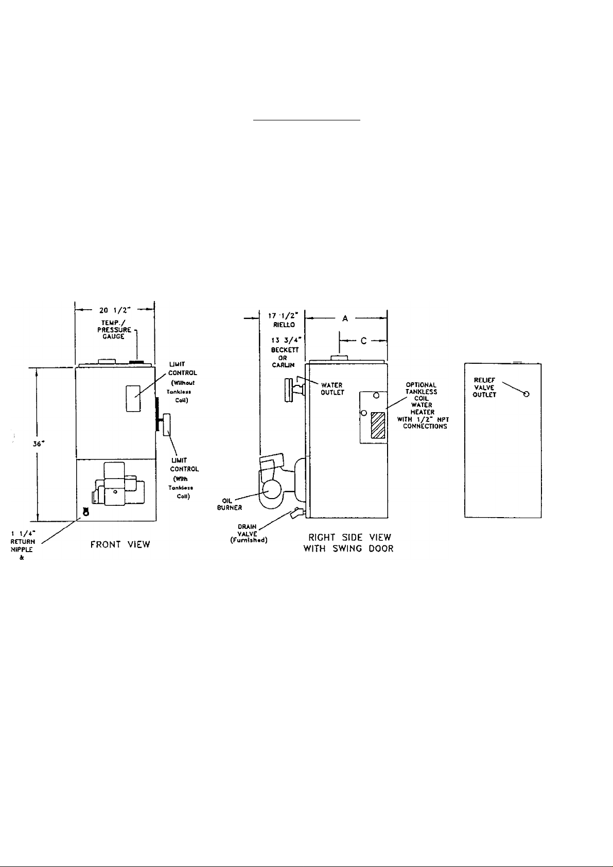
The Empire Water boiler is a natural draft oil fired hot water boiler comprised of cast iron sections. The Empire
Water boiler is available with 3, 4, or 5 cast iron sections. These sections are held together by cast iron push
nipples.
The Empire Water boiler is capable of firing #2 fuel oil from 0.65 gph up to 2.00 gph. Boilers may be purchased
with or without the following options: a Beckett AEG, Carlin EZ, or Riello 40 oil burner, a Taco or Grundfos
circulator with isolation valves, a tankless coil for domestic hot water. All packaged boilers include a swing
door, Honeywell aquastat, temperature and pressure gage, relief valve, drain valve, 2 Delevan oil nozzles for
multiple firing rates (only when purchasing a burner), flue brush, and an extra boiler tap for an expansion tank or
air elimination.
I—I
RCDUCIHG
TEE
BACK VIEW
Page 4
BOILER RATINGS AND CAPACITIES
iioii i;r Mooi;i, no.
wrm
¡ANKI.I'.SS
roil.
3i;w (>ir .lliw.f).“?/. 3
.ii;w 7.ST .ii:W.75Z
3i;w!.oor
4FW.40r 4r;w.'K)z
4i':wi.2,vr 4i;wi 25Z
4i;W1.50T 41iW1.50Z
51-:WI.20T .знзугго/.
5L-:W1.75r
5i-;W2-00'r ,51-:W2.(X)Z
*MBH = !,000 BTU per hour BTU = British Thermal Unit
**Hcalirg Capacity based on 13% C02 with a -0.02” w.c draft over fire, and a #I smoke or less. Testing was done in accordance with the D.O.E.
(Department of Energy) test procedure.
+GPH = Gallons per hour oil at 140,000 BTU per gallon
++A.F.U.E. = Annual Fuel LliMi/airon EfTicicncy based upon D.O.E. test procedure.
wrmoirr
lANKITSS
roil. A В
3EW1.(H)Z
,51; W 1.75/.
.SI-( '
NO
INPUl
♦MUM
’••lil;ATINO
CAPACI rV
*MUH
‘J1 80 70
3 105
140 110
3
4 126 11 1 97 0.90 860 8”X8"X 15’
17,5
4
4 210 178
168 147
5
5 245 209 182 1.75 83,6 8"X8”X 15’
5 280 236 205 2.00 82.0 8"X8"X20' 21
02
150 130 1.25 83.9 8”X8"X 15' 17-3/4
ni-;t
1=U-R
КЛ1 INO
*MBH
80 0-75 85.2 8”X8”X 15' 14-1/2
103 1.00 83.4 8” X 8" X 15' 14-1/2
155 1.50
128 1.20 86.5 8”X8”X 15’ 21
I-IRING
RATE
+(iPU
0.65
f-i-
86,3 S"X8"X 15' 14П/2
82.4
MINIMUM
CHIMNEY
SIZE/HEIGHT
S”X8"X 15’
DIMENSIONS - (inches)
6
6 8
17-3/4
17-3/4
6 8
6
6 9-5/8
6 9-5/8
6 11-1/2
21 6 11-1/2
6 11-1/2
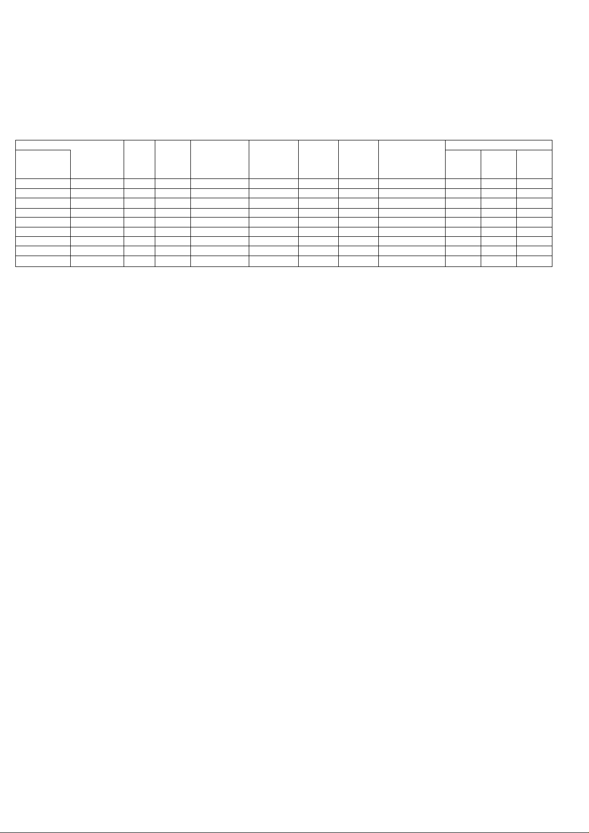
These low pressure oil fired hot water boilers are constructed and hydrostatically tested for a maximum working
pressure of 50 psig (pounds per square inch gage) in accordance with A.S.M.E. (American Society of Mechanical
Engineers) Boiler and Pressure Vessel Code Section IV Standards for heating boilers.
The Heating Capacity indicates the amount of heat available after subtracting the losses up the stack. Most of
this remaining heat is available to heat water. A small portion is heat from the jacket and surfaces of the boiler,
and it is assumed that this heat stays in the structure. The Net I=B=R Rating represents the portion of the
remaining heat that can be applied to heat the radiation or terminal units (i.e. finned tube baseboard, cast iron
radiators, radiant floor, etc.). The difference between the Heating Capacity and the Net I=B=R Rating, called the
piping and pickup allowance, establishes a reserve for heating the volume of water in the system and offsetting
heat losses from the system piping. The Net I=B=R Ratings shown are based on a piping and pickup factor of 1.15
in accordance with the I=B=R Standard as published by the Hydronics Institute. The Net I=B=R Rating of the
boiler selected should be greater than or equal to the calculated peak heating load (heat loss) for the building or
area(s) served by the boiler and associated hot water heating systems. The manufacturer should be consulted
before selecting a boiler for installations having unusual piping and pickup requirements.
c
8
9-5/8
Boilers with the same number of sections are identical to each other except for their firing rate. The firing rate is
detennined by the nozzle size in the oil burner and the oil pressure at the nozzle. For example: Models 3E.65Z,
3E.75Z, and 3E1 .OOZ are the same boiler, without a tankless coil, except for the firing rate of the oil burner.
Models 4E.90T, 4E1.25T, and 4E1.50T are the same boiler, with a tankless coil, except for the firing rate of the oil
biimer.
Each boiler rating plate shows three possible model numbers for a given boiler configuration. The actual model
number is determined by the firing rate of the oil bumer. Boilers that are factory packaged include two nozzles for
two firing rates
These boilers operate on #2 Heating Oil.
Page 5

RULES FOR S AFE INSTALLATION AND OPER.AT10N
1. Read the Owner’s Manual for Safe Operation carefully. Failure to follow the rules for safe operation and
the instructions can cause a malfunction of the boiler and result in death, serious bodily injury, and/or
property damage.
2. Check your local codes and utility requirements before installation. The installation must be in accordance
with their directives, or follow NFPA 31 - Installation of Oil Burning Equipment, latest revision.
3. Before servicing, allow boiler to cool. Always shut off any electricity and oil to boiler when working on it.
4. Inspect oil line and connections for leaks.
5. Be certain oil burner nozzle is the size required. Overfiring will result in early failure of the boiler sections.
This will cause dangerous operation.
6. Never vent this boiler into an enclosed space. Always vent to the outside. Never vent to another roonr or
inside a building.
7. Be sure there is adequate air supply for complete combustion.
8. Follow a regular service and maintenance schedule for efficient and safe operation.
9. Keep boiler area clean and free of combustible material, gasoline and other flammable vapors and liquids.
10. Oil burners are not do-it yourself items. This boiler must be installed and serviced by qualified
professionals using combustion test instruments.
11. Be aware when piping the relief valve that if the system pressure exceeds the safe limit of 30 pounds per
square inch, the relief valve will automatically lift open. Lifting of the relief valve can discharge large
quantities of steam and hot water, which may damage the surroundings. Before installing the relief valve
read the manufacturer’s instructions and maintenance section of the manual on relief valves.
12. Installation and sizing of the expansion tank must consider the heating systems total water volume,
temperature, boiler initial fill pressure, and system arrangement. An improperly installed and sized
expansion tank may result in frequent lifting of the relief valve or other heating system problems. For
proper installation, sizing, and maintenance of the expansion tank follow the guidelines established by
Dunkirk Radiator Corporation and the expansion tank manufacturer.
13. Expansion tank performance and life expectancy can be hindered by overfilling the boiler. Dunkirk
Radiator Corporation recommends an initial fill pressure of 10-12 psig. For higher fill pressures the
expansion tank’s air charge will need to be increased to match the fill pressure. Consult the manufacturer’s
guidelines for sizing and selection.
14. Purging the heating system of air and gases when first putting the boiler’s into service is critical for proper
circulation and quiet performance. Once the air and gases are purged, for boiler installations using float
type vents, the air vents should be closed for normal operation. If air is heard or noticed by a loss of heat,
purge the system and open the vents for a short period of time.
WARNING
This boiler has been designed for residential installations. If used for commercial applications,
all jurisdictional requirements must be met. This may require wiring and/or piping
modifications. The manufacturer is not responsible for any changes to the original design.
DO NOT USE GASOLINE CRANKCASE DRAININGS OR ANY OIL CONTAINING GASOLINE.
Page 6
BEFORE YOU START
Complete all of the following pnor to installing the boiler.
Check to be sure you have selected the right size boiler with the proper capacity. The I=B=R rating of the boiler
A.
selected should be greater than or equal to the calculated peak heating load {heat loss) for the building or area(s)
served by the boiler and associated hot water heating systems. See boiler rating and capacity table previously
listed in this manual. Any heat loss calculations used should be based on approved methods.
Boiler must be supplied with the proper oil supply and oil piping, sufficient fresh combustion air, and a suitable
B.
electrical supply.
Boiler must be connected to a suitable venting system and a piping system adequate to distribute the heating load.
c.
A thermostat must be properly located and installed for control of the heating system.
D.
If there are any doubts as to the various requirements, check with local authorities and obtain professional help where
needed. The OPERATING INSTRUCTIONS, FINAL CHECKS AND ADJUSTMENTS, and MAINTENANCE
sections in this manual are vital to the proper and safe operation of the heating system. Take the time to be sure they
are all done.
LOCATING THE BOILER
Place the boiler in a location centralized with the piping system and as close to the chimney as possible.
1.
The boiler must be level. If necessary use metal shims beneath the boiler’s feet.
2.
Use a raised base if the floor can become wet or damp.
3.
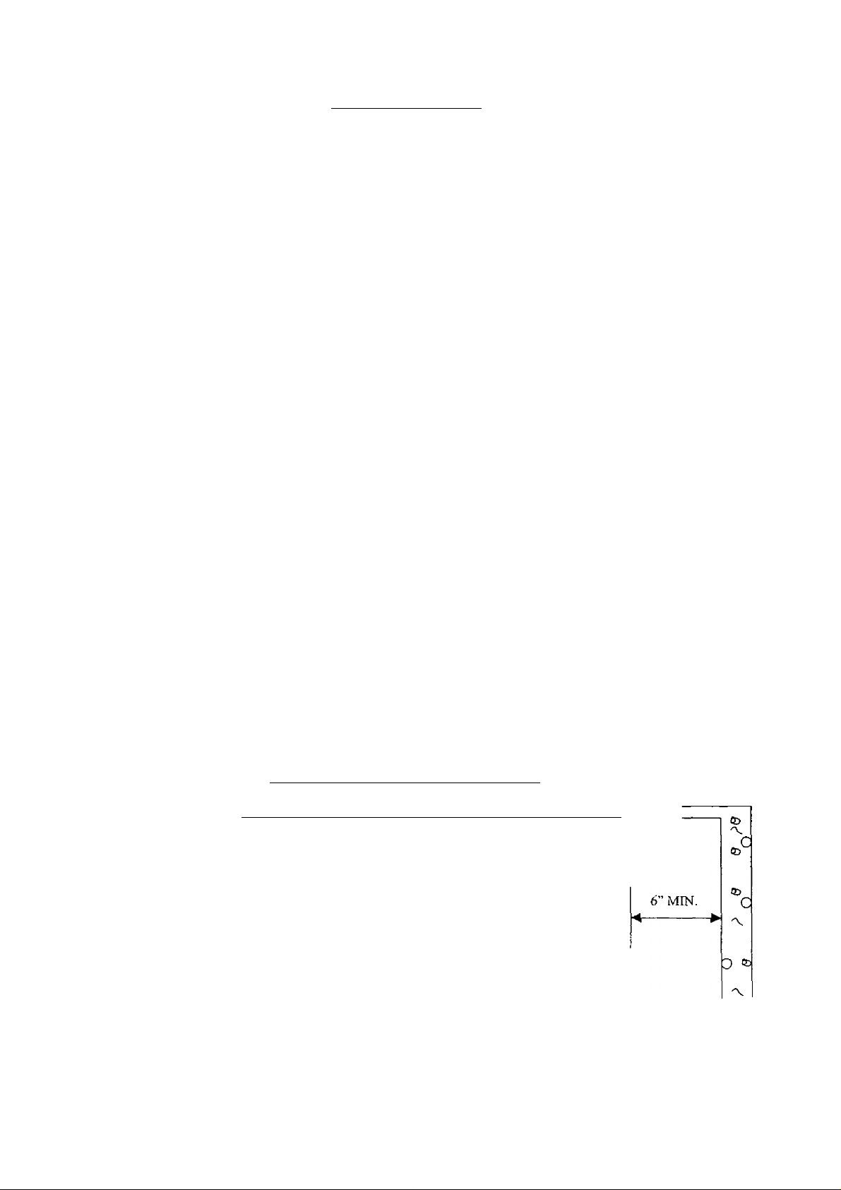
Maintain clearances for fire safety as well as servicing. An 18” clearance must be maintained at a side where
4.
passage is required for access to another side for cleaning, servicing, inspection, or replacement of any parts that
normally may require such attention. Boilers must be installed at least 6” from combustible material on all sides
and above. Allow at least 24” front clearance for servicing.
Fresh air for combustion must be available at the front of the boiler. Fresh air for ventilation must be available to
5.
the front AND rear of the boiler. Air passages must be free of obstructions at all times. Ventilating and
combustion air must enter boiler room without restrictions.
The floor supporting the boiler must be non-combustible and sufficiently stable. If it is combustible, place the
6.
boiler on 2” concrete patio blocks or 2” Cladlite™ Pad. The blocks or pad must be under the entire boiler to
protect the floor.
Be sure installation is in accordance with the requirements of the local authorities having jurisdiction. Compliance
7.
with these regulations is required. In the absence of local codes, follow NFPA 31 - Installation of Oil Burning
Equipment, latest revision.
0
5>
C/\
ED
'V
O
'V
CD
MINIMUM CLEARANCE DIMENSIONS
-A. o "" Cb o ~!b to ~ u ID 'V Q
T
6” MIN.
i.
24" MIN.
6” MIN. /18” WITH COIL
BOILER
FRONT
Page 7
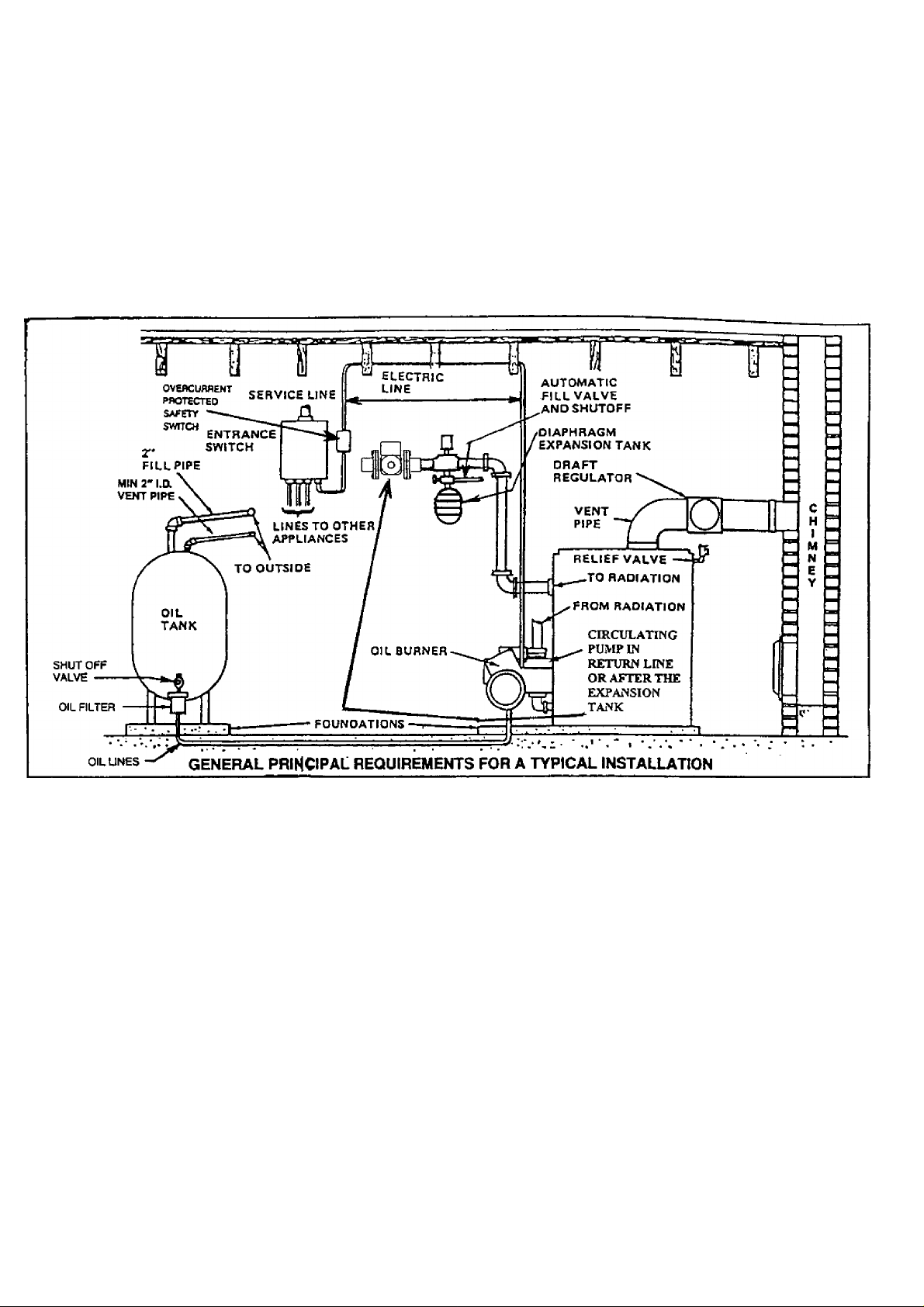
ALWAYS KEEP THE iVLANUAL FUEL SUPPLY VALVE SHUT OFF, IF THE
BURNER IS SHUT DOWN FOR AN EXTENDED PERIOD OF TLME.
INSTALLATION RJEOUIREMENTS
Page 8
FRESH AIR FOR COMBUSTION
WARNING
Be sure to provide enough fresh air for combustion. Enough air ensures proper
combustion and assures that no hazard will develop due to the lack of oxygen.
NOTE
If you use a fireplace or a kitchen or a bathroom exhaust fan, you should install an
outside air intake. These devices will rob the boiler and water heater of combustion air.
You must provide enough fresh air to assure proper combustion. The fire in the boiler uses oxygen. It must have a
continuous supply. The air in the house contains only enough oxygen to supply the burner for a short time. Outside
air must enter the house to replace the air used by the burner. Study the following examples 1 and 2 to determine your
fresh air requirements.
EXAMPLE 1: Boiler Located in Unconfined Space
If your boiler is in an open area (unpartitioned basement) in a conventional house, the air that leaks through the cracks
around the doors and windows will usually be adequate to provide air for combustion. The doors should not fit tightly.
Do not caulk the cracks around the windows.
An unconfined space is defined as a space whose volume is not less than 50 cubic feet per 1,000 Btu per hour of the
total input rating of all appliances installed in that space.
EXAMPLE 2: Boiler Located in Confined Space
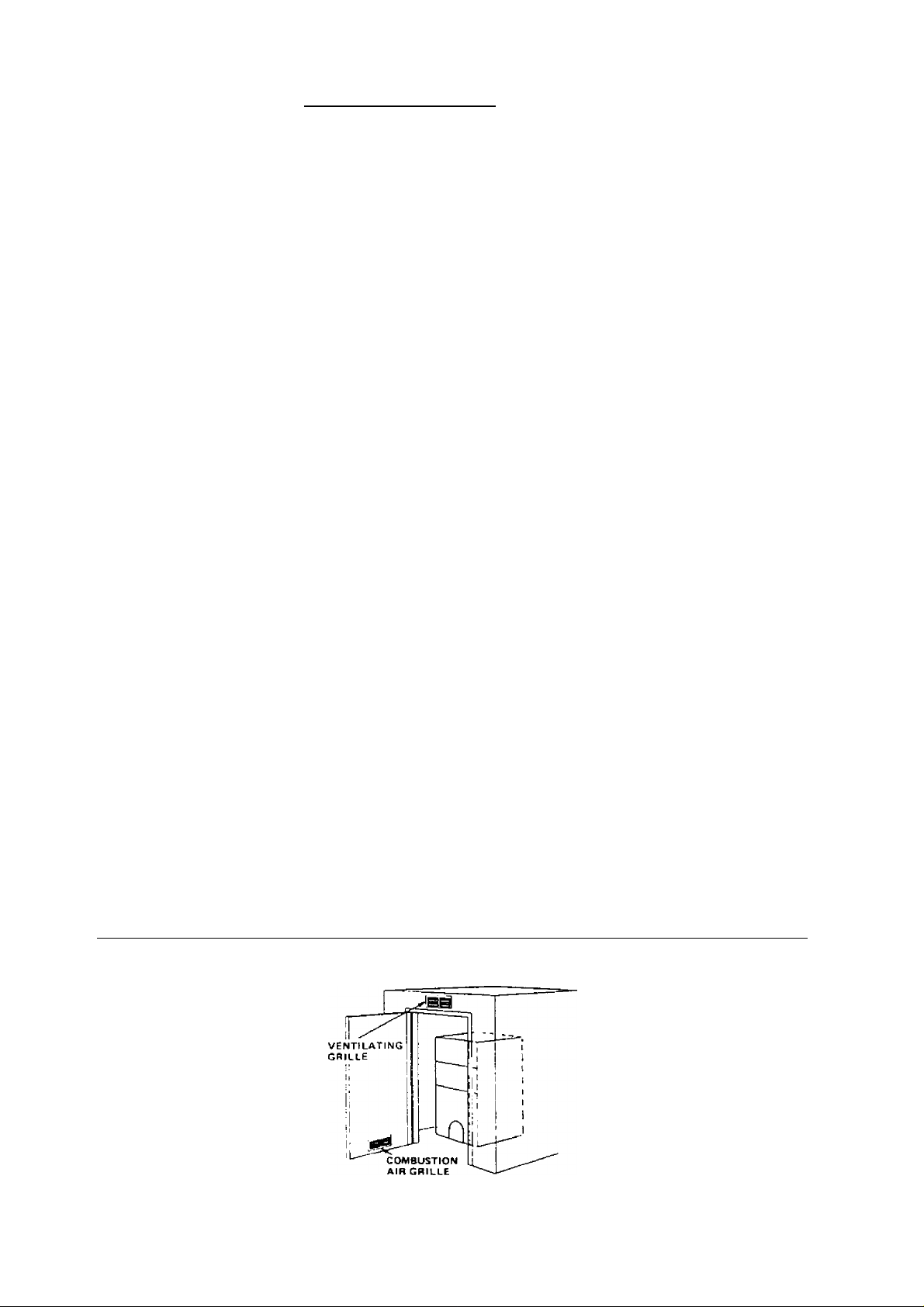
A. All Air from Inside the Building: The confined space shall be provided with two permanent openings
communicating directly with an additional room(s) of sufficient volume so that the combined volume of all spaces
meets the criteria for an unconfined space. The total input of all combustion equipment installed in the combined
space shall be considered in making this determination. Each opening shall have a minimum free area of one
square inch per 1,000 Btu per hour of the total input rating of all combustion equipment in the confined space, but
not less than 100 square inches. One opening shall be within 12 inches of the top and one within 12 inches of the
bottom of the enclosure.
Example: Your boiler is rated at 100,000 Btu per hour. The water heater is rated at 30,000 Btu per hour. The
total is 130,000 Btu per hour. You need two grilles, each with 130 square inches of FREE opening. Metal grilles
have about 60% FREE opening. To find the louvered area needed, multiply the free opening required by 1.7 (130
X 1.7 = 221.0 sq. in. louvered area). In this example, two grilles each having an 8” x 30” (240 sq. in.) louvered
area would be used.
AIR OPENINGS FOR BOILER LOCATED IN CONFINED SPACE (CLOSET OR UTILITY ROOM!
Page 9
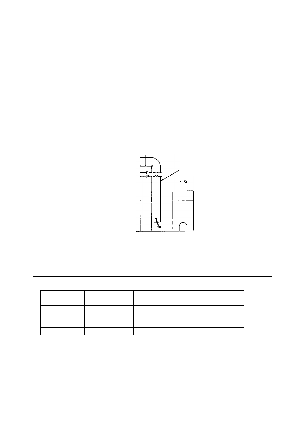
B. All Air from Outdoors: The confined space shall be provided with two permanent openings, one
commencing within 12 inches of the top and commencing within 12 inches of the bottom of the
enclosure. The openings shall communicate directly, or by ducts, with the outdoors or spaces {crawl or
attic) that freely communicate with the outdoors.
1. When directly communicating with the outdoors, each opening shall have a minimum free area of
one square inch per 4,000 Btu per hour of total input rating of all equipment in the enclosure.
2. When communicating with the outdoors through vertical ducts, each opening shall have a minimum
free>area of one square inch per 4,000 Btu per hour of total input rating of all equipment in the
enclosure.
3.
When communicating with the outdoors through horizontal ducts, each opening shall have a
minimum free area of one square inch per 2,000 Btu per hour of total input rating of all equipment in
the enclosure.
4.
When ducts are used, they shall be of the same cross-sectional area as the free area of the openings to
which they connect. The minimum dimension of rectangular air ducts shall be not less than three
inches.
f=RESH
AIR
DUCT
BOILER
FRESH AIR DUCT CAPACITIES FOR DUCTS SUPPLYING FRESH AIR TO BOILER IN TIGHTLY
CONSTRUCTED HOUSES
Fresh Air
Duct Size
3-'/2”x 12”
8” X 8”
8”x 12”
8”x 16” 512,000
Mesh Screen
(Btuh)*
144,000
256,000
384,000
Wood Louvers
(Btuh)*
36,000
64,000
96,000
128,000
Metal Louvers
(Btuh)*
108,000
192,000
288,000
384,000
*Btuh = British Thermal Units per hour based on opening covered by ‘/4” mesh
screen, wood louvers, or metal louvers.
Page 10
SYSTEM PIPING
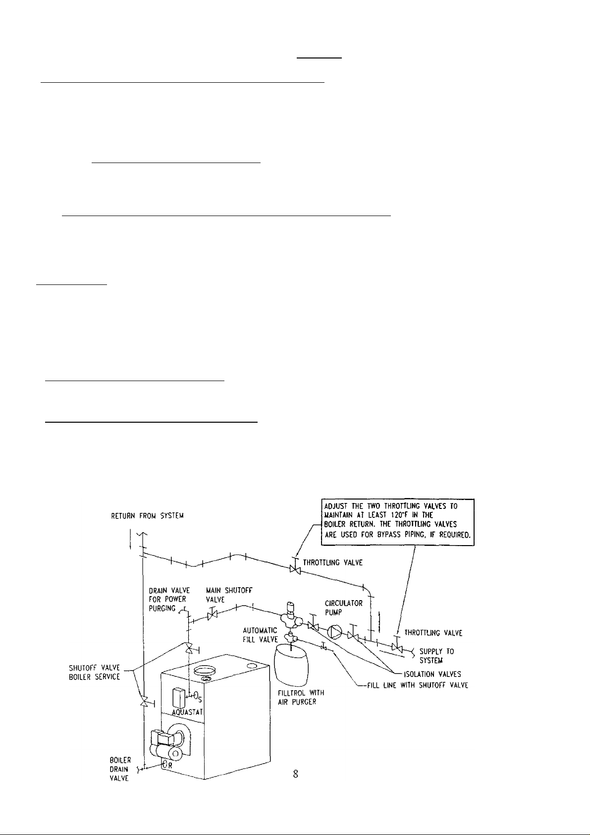
1. }Vhen the installation of the boiler is for a new heatine system, first install all of the radiation units
(panels, radiators, baseboard, or tubing) and the supply and return mains. After all heating system piping
and components have been installed, make final connection of the system piping to the boiler. It is
recommended to mount the circulating pump on the supply side piping, such that it pumps away from the
expansion tank. Refer to the figures on the next pages.
2. A hot wat^ boiler installed above radiation level must be equipped with a low water cut off device. A
periodic inspection is necessary, as is flushing of float type devices, per low water cut off manufacturers
specific instructions.
3. The packaged boiler unit is set up with 1-1/4” NPT supply and return pipine from the front of the boiler.
The boiler supply and return piping can be moved to the rear of the boiler. The boiler should not be piped
return line to the front, supply line to the rear, or vice versa, as this will cause the boiler water to short
circuit the heat exchanger. Piping connections may require additional fittings and parts.
4. The relief valve is meant to be installed in the back side of the rear section using the 3/4” nipple and street
ell provided in the parts bag. Connect a discharge pipe of the same pipe size (3/4”) to carry any water away
to a drain. Do not connect directly to a drain, but leave an air gap. No shutoff of any description shall be
placed between the safety relief valve and the boiler, or on discharge pipes between such safety valves and
the atmosphere. Installation on the safety relief valve shall conform to the ANSI/ASME Boiler and Pressure
Vessel Code, Section IV. The manufacturer is not responsible for any water damage.
5. When connecting the cold water supply to the pressure reducing valve, make sure that a clean water supply
is available. When the water supply is from a well or pump, a sand strainer should be installed at the pump.
6. The minimum boiler supply water temperature setting on the aquastat is 140°F. If the boiler is used in a
heating system where supply water temperatures below 140°F are desired, a suitable method, such as, the
use of bypass piping shown in the figure below, a 3 way or 4 way mixing valve, or some other means
needs to be used to ensure return water temperatures to the boiler are no less than 120°F. When the boiler is
operated with return water temperatures less than 120°F, condensation may form in the boiler and venting.
This condensation is corrosive and can eventually cause severe damage to the boiler and venting system.
Page 11
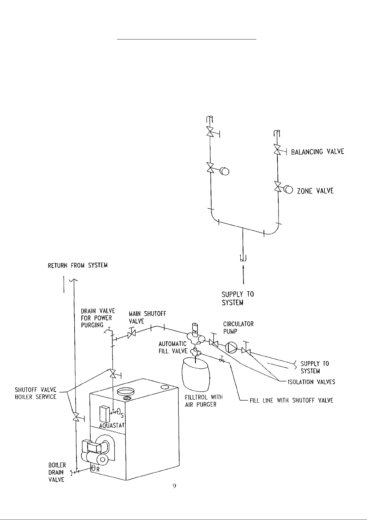
SYSTEM PIPING ARRANGEMENT
ZONING WITH ZONE VALVES
> CIRCULATOR ON SUPPLY PIPING PUMPS
AWAY FROM EXPANSION TANK
> PIPING ARRANGED FOR “POWER PURGING”
AIR OUT OF SYSTEM PIPING, REFER TO THIS
MANUAL’S SECTION ON “FILLING THE
SYSTEM WITH WATER” OPTION #1
Page 12
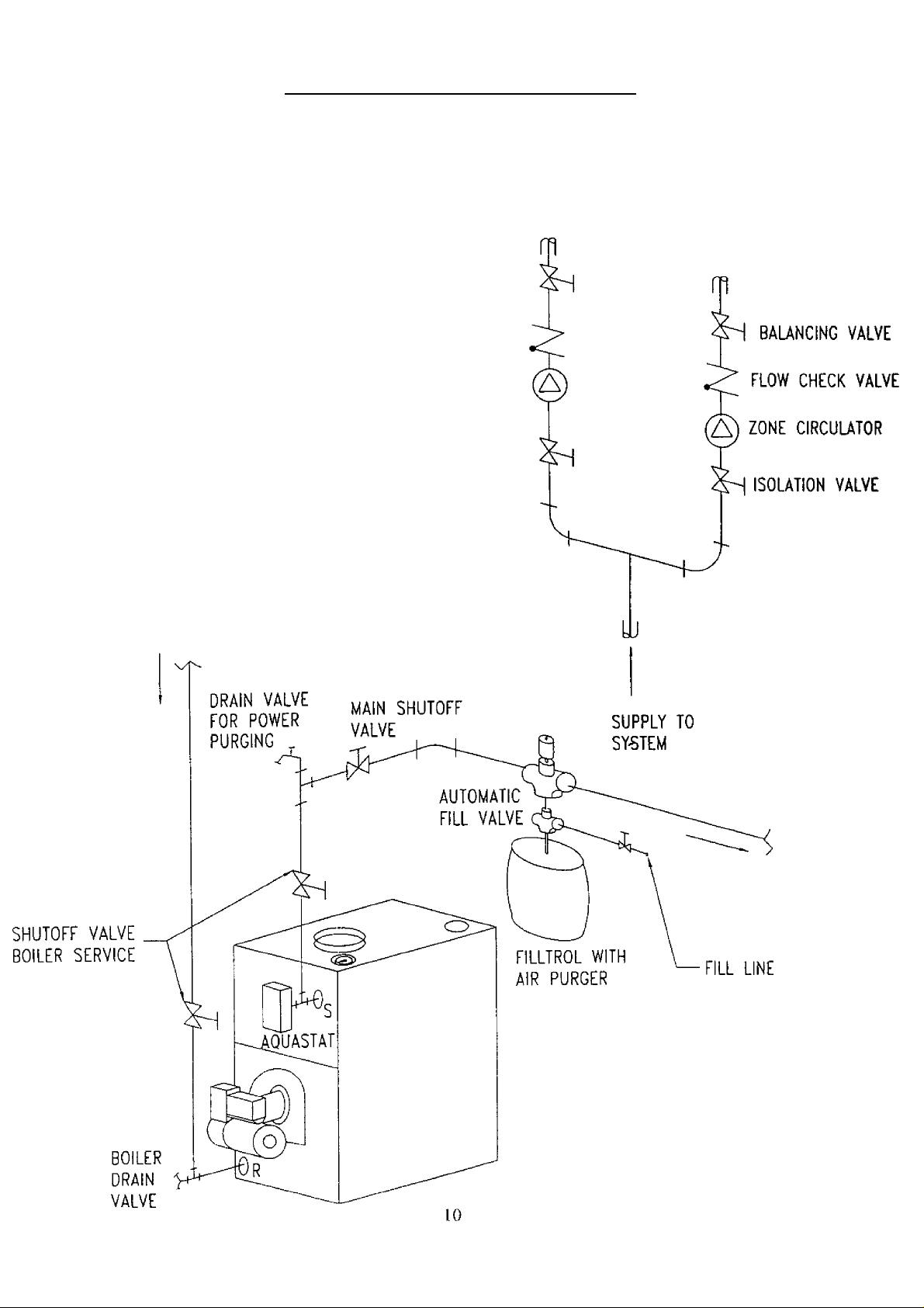
SYSTEM PIPING ARRANGEMENT
ZONING WITH CIRCULATORS
> CIRCULATOR ON SUPPLY PIPING PUMPS
AWAY FROM EXPANSION TANK
> PIPING ARRANGED FOR “POWER PURGING”
AIR OUT OF SYSTEM PIPING, REFER TO THIS
MANtlAL’S SECTION ON “FILLING THE
SYSTEM WITH WATER” OPTION #1
RETURN FROM SYSTEM
SUPPLY TO
SYSTEM
VALVE
Page 13
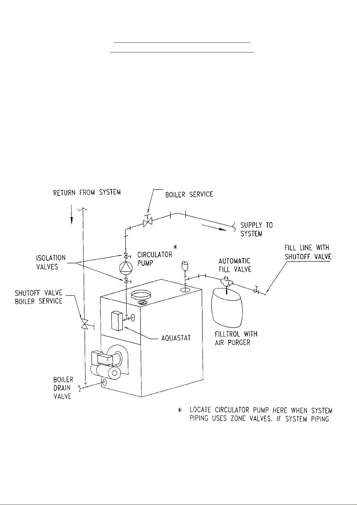
SYSTEM PIPING ARRANGEMENT
ALTERNATE NEAR BOILER PIPING
> DIAPHRAGM EXPANSION TANK MOUNTED OFF THE BOILER
> CIRCULATOR ON SUPPLY PIPING PUMPS AWAY FROM EXPANSION TANK
> PER THIS MANUAL, USE OPTION #2 IN “FILLING THE SYSTEM WITH WATER”
> THIS PIPING ARRANGEMENT CAN BE USED WITH ZONE VALVES OR ZONE CIRCULATORS
SHUTOFF VALVE
11
USES ZONE CIRCULATORS, USE THIS CIRCULATOR
AS A ZONE CIRCULATOR
Page 14
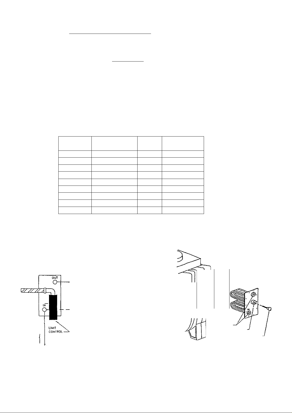
7, Boilers may be factory packaeed with a tankless heater coil see figure below. This coil provides
instantaneous heating of water for domestic use - if proper burner and water supply line controls are used.
Tankless coils are meant to provide domestic hot water for intermittent draws, not continuous flow.
IMPORTANT
Do not use a tankless coil if your water is excessively hard with
lime or other deposits which will accumulate inside the coil.
When using a tankless coil, the boiler has been configured so the Honeywell L8124C Combination
Hi/Low Limit Aquastat Relay mounts on a thermowell (provided) which needs to be installed in the 3/4”
tapping on the tankless coil. By mounting the aquastat on the coil, the tankless coil performance is
maximized by making the burner respond more quickly to a call for domestic hot water. A tempering
valve (mixing valve) is also recommended as shown in figure below. A flow restrictor may be required
on the tankless coil inlet piping so that flow rates are matched to boiler heat input (see table below).
TANKLESS COIL
Boiler
Model
Burner Firing
Rate (gph)
3EW.65T 0.65
3EW.75T
0.75 105 3.00
3EW1.00T 1.00 140
4EW.90T 0.90 126
4EW1.25T
1.25 175 3.50
4EW1.50T 1.50 210
5EW1.20T
5EW1.75T
1.20 168 3.45
1.75 245 4.00
5EW2.00T 2.00 280
Input Tankless
(MBH)
91
Rating (gpm)t
2.90
3.25
3.15
3.75
4.25
Gallons of water per minute heated from 40°F to I40°F with
200°F boiler water temperature, intermittent draw
UNTEUrtnCO HOT WATEJt
( « „«««M ..M HOT WATEH
CENTER LINE
or COLO TAP
r 10 ir
n—
TEMPEfHNC
valve
SHUT-Orr
VALVE
COLO water «NLtr
12
ty
u
ft' NPT
NPT '
CONTROL WELL
Page 15
8. Antifreeze added to boilers must be non-toxic, and must be of a type specifically intended for use in closed
hydronic heating systems. Under no circumstances should automotive antifreeze be used. Antifreeze used
in any boiler may reduce capacity by 10% or more and increase fuel consumption. Tankless coil
performance will fall as concentration of antifreeze is increased. Refer to boiler and piping water volumes
tables in this manual.
BOILER WATER VOLUMES
Number of
Boiler Sections
3 9.6
4 11.6
5
Total Volume
(Gallons)
13.7
PIPING WATER VOLUMES
PIPE SIZE
%”
1”
1-1/4”
1-1/2”
2”
factor in table to determine volume in gallons.
COPPER PIPE
FACTOR
82.5
40.0
23.3
15.3
10.8
6.2
STEEL PIPE
FACTOR
63.5
36.0
22.2
12.8
9.5
5.8
Page 16

For oil-fired boilers for connections to vents or chimneys, vent installations shall be in
accordance with applicable provisions of INSTALLATION OF OIL BURNING
EQUIPMENT, NFPA-31 - latest revision, and applicable provisions of local building codes.
CHIMNEY AND CHIMNEY CONNECTIONS
This is a very important part of your heating system. No boiler, however efficient its design, can perform
satisfactorily if the chimney that serves it is inadequate. Check your chimney to make certain that it is the
right size, properly constructed and in sound condition.
It is cheaper to rebuild a poor chimney than to pay excessive fuel bills. If yours is an old chimney, a new
steel liner or a new prefabricated chimney may be the best solution. The following chart shows
recommended minimum chimney sizes based on Table 3 and Figure 6 of the I=B=R Testing and Rating
Standard for Heating Boilers, Sixth Edition, June 1989.
RECOMMENDED MINIMUM CHIMNEY SIZES
FIRING RATE
(gph)
0.60- 1.30
1.31 - 1.80
1.81-2.00
For elevations above 2,000 feet above sea level, add 3 feet to the chimney heights. See Figure below.
CHIMNEY
HEIGHT (ft)
15 8” X 8” 6”
15 8” X 8”
20
NOMINAL
CHIMNEY
AREA
8” X 8”
ROUND LINER-
INSIDE
DIAMETER
7”
8” 6-3/4” X 6-3/4”
SQUARE LINER-
INSIDE
DIMENSIONS
6-3/4” X 6-3/4”
6-3/4” X 6-3/4”
For additional chimney design and sizing information, consult the ASHRAE 1996 HVAC Systems and
Applications Handbook, Chapter 30, Gas Vent and Fireplace Systems; or the National Standard for
Chimneys, Fireplaces, Vents and Solid Fuel Burning Appliances, ANSI/NFPA 211.
CHIMNEY CONNECTOR AND DRAFT REGULATOR
Venting the boiler requires a 6” diameter chimney connector pipe and using the draft regulator packed with
the boiler. Properly installed, the regulator will control the draft automatically. It is better to install it in a
horizontal section of pipe, but it may be installed in an angled or vertical section of pipe. Make certain that
the “top” of the regulator is at the top - and that the short pipe section which holds the vane is horizontal.
Even though locating the draft regulator close to the chimney reduces noise, install the draft regulator as
close as practicable to the boiler.
To install the chimney connector, start at the boiler with a vertical pipe and then elbow - then install the draft
regulator making it horizontal. When the regulator is in place, start at the chimney and work back to the
regulator. Join the two sections with a drawband. The horizontal pipe must slope up toward the chimney at
least 1/4 inch per linear foot of venting. The chimney connector must not leak and must be firmly supported.
J oin each of the sections with at least two sheet-metal screws. Support every second section with a stovepipe
wire.
Maintain a minimum vent pipe clearance of 18” from the surface of the vent to wood and other
combustible materials.
14
Page 17
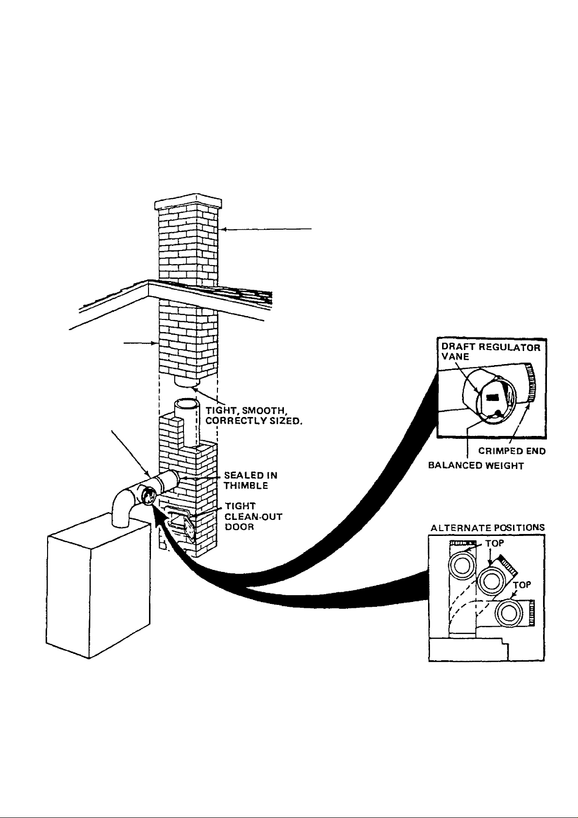
MUST BE AT LEAST 4
INCHES THICKAND BE TIGHT.
TYPICAL CHIMNEY CONNECTION
MUST BE REQUIRED MIN
IMUM HEIGHT. MUST BE
AT LEAST 3 FT. HIGHER
THAN HIGHEST PART OF
PASSAGE THROUGH
ROOF. MUST BE AT
LEAST 2 FT. HIGHER
THAN ANY NEIGHBORING
OBJECT. MUST HAVE AN
UNOBSTRUCTED TOP
OPENING.
MUST SLOPE UP
AT LEAST 1/4 INCH
PER FOOT OF
HORIZONTAL RUN
DRAWBAND
LAST PIECE
INSTALLED
Page 18
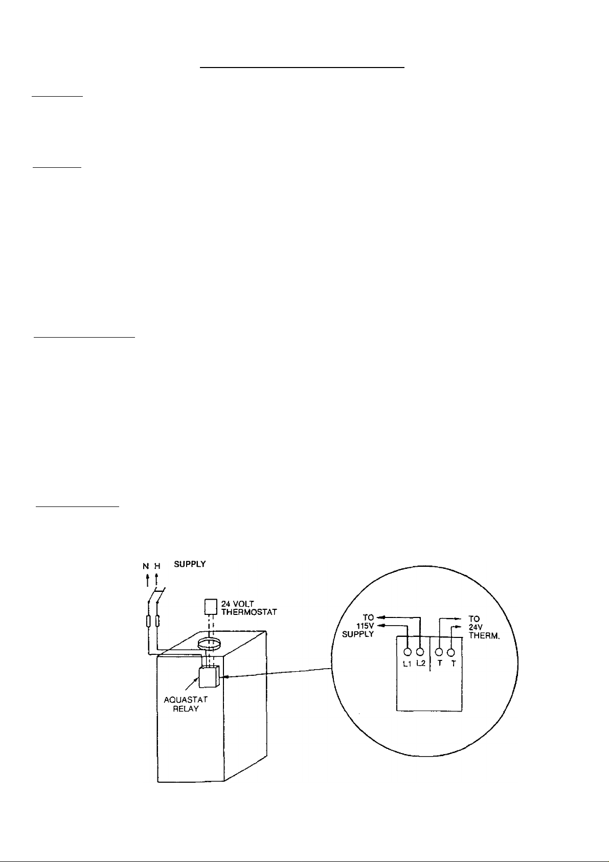
ELECTRICAL CONNECTIONS
Thermostat
Install a 24"VoIt thermostat (not provided) in a proper location. The location of the thermostat has an
important effect on boiler system operation. BE SURE TO FOLLOW THE INSTRUCTIONS INCLUDED
WITH THE THERMOSTAT.
Grounding
Permanently ground the boiler according to local codes and the National Electrical Code. Run a 14 gauge or
heavier copper wire from the boiler to a grounded connection in the service panel or a properly driven and
electrically grounded ground rod.
WARNING
Turn off electric power at fuse box before making any
line voltage connections. Follow local electrical codes.
Electric Power Supply
All electrical work must conform to your local codes as well as the National Electrical Code. If you are not
familiar with wiring and codes in general, have a competent electrician do this job.
On packaged boilers, the boiler controls are all wired at the factory. You need only connect a 115 volt
electrical supply to the LI and L2 terminals on the aquastat relay and two thermostat wires to the T and T
terminals on the same aquastat relay (see figure below).
Run a separate circuit from a separate overcurrent protection device in your electrical service entrance panel.
This should be a 15 ampere circuit. Locate a shut-off switch at the boiler. It must be turned off during any
maintenance. Solder and tape or securely fasten these connections with wire nuts.
Oil Burner Wiring
For boilers packaged with oil burners, the burners are wired at the factory. For boilers shipped knockdown
or packaged without a burner, wiring connections are shown in the electrical wiring diagrams of this manual.
115V 60 CYCLE
16
Page 19

Warranty
1
KENNMORE CAST IRON BOILERS
FULL ONE YEAR WARRANTY ON HOT WATER AND GAS STEAM CAST IRON BOILERS
For one (1) year from the date of installation, when this boiler is installed and maintained in accordance
with our instructions. Sears will repair defects in material or workmanship in the boiler, free of charge.
LiMfTED 12 YEAR WARRANTY ON STEAM CAST IRON BOILERS
After one (1) year and through twelve (12) years from the date of installation. Sears will furnish a replacement
heat exchanger, if the heat exchanger in the boiler is defective. YOU PAY FOR LABOR.
LIMITED 20 YEAR WARRANTY ON HOT WATER CAST IRON BOILERS
After one (1) year and through twenty (20) years from the date of installation, Sears will furnish a replacement
heat exchanger if the heat exchanger in the boiler is defective. YOU PAY FOR LABOR.
SEARS INSTALLATION WARRANTY
in addition to any warranty extended to you on the Sears merchandise involved, which warranty becomes
effective the date the merchandise is installed, should the workmanship of any Sears arranged installation
prove faulty within one year, Sears will, upon notice from you, cause such faults to be corrected at
no additional cost to you.
FOR WARRANTY SERVICE, SIMPLY CONTACT THE NEAREST SEARS STORE OR SERVICE
CENTER THROUGHOUT THE UNITED STATES. This warranty gives you specific legal rights, and
you may also have other rights which vary from state to state.
IMPORTANT
The following are the responsibilities of the user and are
not covered by the Warranty.
1 Filter clearing or replacement.
2. Damage to unit or unsatisfactory operation due to improper
cleaning or use of unit in corrosive atmosphere.
3. Damage to unit or unsatisfactory operation due to blown
fuses or inadequate or interrupted electrical protective
devices
4. Damage to unit caused by the use of components or other
accessories not compatible with the unit.
Vi
If the unit IS removed from the place it was originally
installed, this Warranty becomes void.
Damage to the unit caused by accident, abuse, negligence,
misuse, riot, fire, flood, or acts of God
SEARS ROEBUCK AND COMPANY
D/817WA
Hoffman Estates, IL 60179
Page 20

MAIN AIR VENT: for down flow systems or diaphragm type expansion tanks fnot provided)
Before a system is filled with water, there is air in the pipes and radiation units. Some of the air will be
trapped as the system is filled, it is possible to eliminate most of this air through the air vents on the
radiation units. A main air vent will speed and simplify this process. The main air vent should be installed
on the highest point in the supply main when all radiation is below the top of the boiler.
AUTOMATIC FILL VALVE inot provided!
For safe, efficient operation, a hot water system must be filled with water. Adding new water, when needed
can be done manually (by use of a hand valve in the water supply line). This requires regular attention to the
system’s needs. An automatic fill valve or pressure reducing valve accomplishes this without attention. It is
installed in the supply line on hot water boilers only. The valve operates through water pressure
differentials. It does not require an electrical connection.
BURNER SOLENOID VALVE fprovidedl
The Beckett and Carlin oil burner’s use a standard solenoid valve. Upon burner shut down, a standard
solenoid valve stops the flow of oil to the nozzle. Without the solenoid valve, the oil pump continues to
pump oil to the burner nozzle until the burner motor winds down below the pumps cut-off speed. The Riello
oil burner has a delay solenoid valve. The delay solenoid valve provides the same shut down action as the
standard solenoid valve, plus on burner start up the delay solenoid valve remains closed for an additional 15
seconds. This allows the burner fan motor to pre-purge the combustion chamber and the oil pump to bring
the supply oil pressure up to its set point helping to provide a clean light off
AOUASTAT RELAY CONTROL fprovidedi
The water temperature limit control in the aquastat relay is adjustable and may be set: as low as 140°F so
long as return water temperatures to the boiler are no less than 120°F, or as high as 240°F so long as the
boiler and heating system have adequate circulation to remove the heat from the boiler otherwise steam may
be created in the boiler. Refer back to SYSTEM PIPING section for more information.
DRAIN VALVE fprovidedl
The drain valve is a manually operated valve that provides a means of draining all the water from the boiler
and heating system. It should be installed in the reducing tee where the return line enters the boiler.
CIRCULATOR (provided)
Every forced hot water system requires a circulator. A separate circulator or zone valve is required for each
zone, if there are two or more zones. The circulator must have the capacity to provide the circulation
required by the heating system. The circulator should be connected to the supply main and must be wired
into the boiler’s electrical system. See the SYSTEM PIPING section for piping configurations with the
circulator located on the supply main piping using zone circulators or zone valves. When the piping is
arranged with zone circulators and no bypass piping, the circulator provided with the boiler may be used as a
zone circulator. Both piping arrangements allow the circulator to pump away from the expansion tank and
show how the piping should be arranged to allow the heating system to be easily purged of air.
18
Page 21

FILLING THE BOILER
HOW A HOT WATER SYSTEM OPERATES
The entire heating system (boiler, piping, and radiation units) is filled with water. As the water in the boiler
is heated, it is circulated from the top of the boiler through the supply main to the radiation units. The cooler
water in the radiation units flows back through the return piping through the return main into the boiler. This
arrangemenl provides positive and rapid response to the thermostat.
FILLING THE SYSTEM WITH WATER
OPTION #1 - This method utilizes the boiler piping as shown in the figure on the previous page.
a) Close the main shutoff valve, isolation valves, and zone valves (if applicable). If bypass piping is
installed, also close the two throttling valves. Leave the boiler service shutoff valve (if installed) and the
balancing valves to each heating zone fully open.
b) Open the following valves in order: the drain valve for power purging, isolating valves before and after
the boiler circulator (if applicable), both throttling valves (if applicable), and then open the fill line
shutoff valve. Water will fill the bypass piping and push the air through the piping and out the power
purging drain valve. When the power purging drain valve runs air free, close the bypass piping throttling
valve (leaving the throttling valve to the supply piping fully open).
c) Next, open the isolation valve (or zone valve) to the first zone. Water will fill the piping and push any air
out the power purging drain valve. When the power purging drain valve runs air free, close the isolation
valve or zone valve). Repeat this procedure for the remaining heating zones.
d) Once all zones are filled with water and purged of air, close the power purging drain valve and fill line
shut off valve, open the main shutoff valve, and adjust the throttling valves and balancing valves as
required.
OPTION #2 - Close the air vents on all radiation units. Open the valves to the radiation units. Make sure
the boiler drain valve, expansion tank drain cock, and the air bleed screw on the expansion tank drain fitting
are closed. Open the fill valve on the piping to the expansion tank. Open the water inlet to the boiler and
leave it open. Open the air vent on the lowest radiation unit. When all the air has escaped and water starts to
flow from the vent, close it. Go to the next radiation unit, and repeat this process until finishing with the
highest radiation unit. If the heating system has automatic vents, this manual venting is unnecessary but it
will speed up the proper filling of the system.
If the system is a closed expansion tank system, an automatic fill valve is needed. Leave the automatic fill
valve open to refill the system automatically as needed. Note the initial fill pressure on the boiler’s
temperature / pressure gauge, which should be 10-15 psig. Any lowering of the pressure from its initial fill
pressure indicates a loss of water due to leakage. The automatic fill valve should then compensate for this
water pressure loss. If it does not, manually open this valve to refill the system until the needle is again
pointing to the same pressure reading. Instmctions are packaged with the valve.
19
Page 22

BECKETT OIL BURNER. NOZZLE. AND AIR SETTINGS
BOILER
MODEL
3EW.65*
3EW.75
3EW1.00 0.85-70°B
4EW.90 0.75-80°A
4EW1.25
4EW1.50
5EW1.20 1.00-60°8 1.20 0 NO
5EW1.75 1.50-45°B
5EW2.00 1.65-60°B
*To fire the SEW.65 on rate, the oil pressure must be increased to 175 psig.
All Beckett oil burners for the EW boiler are factory preset at 140 psig.
DELEVAN FIRING HEAD-ADJ.
OIL NOZZLE
0.50-80° B 0.65 FO - 1 1/8 YES
0.65-70'B
1.00-80°A 1.25 F6 - 1 1/8
1.25-80°A 1.50 F6 - 1 1/8
RATE (gph) OR SETTING BAFFLE
0.75
1.00
0.90 F3 - 1 1/8
1.75
2.00
F3 - 1 1/8 YES
F3 - 1 1/8
2 NO
4 NO
LOW FIRE
NO
NO
NO
NO
AIR STATIC
SHUTTER / BAND
10/0
10/0
10/2 3-1/2 AFG F-HEAD
8/0
10/0
10/2 3-3/8 AFG F-HEAD
10/1.5
10/4
10/5
CARLIN OIL BURNER. NOZZLE. AND AIR SETTINGS
BOILER DELEVAN ■ FIRING HEAD A)R BAND CARLIN
MODEL
3EW.65 0.55-70°B
3EW.75 0.65-60°B 0.75 0.60 / 0.65
3EW1.00 0.85-60°B 1.00 0.85 /1.00
4EW.90 0.75-60° B
4EW1.25 1.00-60°B
4EW1.50 1.25-60°B
5EW1.20 1.00-60°B
5EW1.75
5EW2.00 1.65-70°B
OIL NOZZLE
1.50-60°B
RATE (gph) SETTING
0.65
0.90
1.25
1.50
1.20
1.75
2.00 1.65/1.75
0.50 0.52
0.75 0.75
0.85/1.00 0.90
1.10/1.25 1.25
0.85/1.00 0.90
1.50 1.65
SET POINT
0.60
0.80
1.95
BURNER*
EZ-1 HP
EZ-1 HP
EZ-1 HP
EZ-1 HP
EZ-1 HP
EZ-1 HP
EZ-1 HP
EZ-2 HP
EZ-2 HP
OIL
PLATE BURNER
3-5/8 AFG F-HEAD
3-1/2 AFG F-HEAD
3-1/2
3-3/8 AFG F-HEAD
2-3/4 AFG 50 MD
2-3/4 AFG 50 MD
2-3/4 AFG 50 MD
AFG F-HEAD
*All Carlin EZ-1 HP and EZ-2 HP oil burners are factory preset at 150 psig.
RIELLO 40 OIL BURNER. NOZZLE. AND AIR SETTINGS
BOILER
MODEL OIL NOZZLE
3EW.65 0.50-70°W 0.65 0.5/ 2.0
3EW.75 0.65-70°W 0.75 2.0 / 2.2
3ËW1.00
4EW.90 0.75-70°W 0.90 1.5/2.6 160
4EW1.25 1-00-70°W 1.25 2.5/3.8
4EW1.50 1.25-70°W 1.50 4.0/7.0 175
5EW1.20
5EW1.75 1.50-70“W 1.75 2.0 / 3.8
5EW2.00 1.75-70°W 2.00 2.5/4.1 155
*AII Riello 40 F5 and F10 oil burners are factory preset at 145 psig.
DELEVAN FIRING TURBULATOR/AIR
RATE (gph) SHUTTER SETTING (PSIG)*
0.85-70°W
1.00-70°W
1.00
1.20
2.0/3.2 170
2.5 / 3,5
OIL PRESSURE RIELLO 40
NOTE; All burners use an insertion depth of 2-1/4" and fired at a
overfire draft of -0.02 inches w.c. The burner settings provided
are intended for initial start up only. Final adjustment must be made
using combustion test instruments.
______________________________________
155
150
170
150
155
BURNER MODEL
F5
F5
F5
F5
F5
F5
F5
F10
F10
38
Page 23

NOZZLES AND ELECTRODES: Use the proper size, spray angle, and spray pattern nozzle. Refer to the
recommended nozzle selection charts at the end of this manual. To install a nozzle, remove the nozzle line
electrode assembly, if necessary remove the retention ring assembly, and then install and tighten the nozzle.
Be careful not to damage the electrode insulators or the bend the electrode tips. After installing the nozzle,
reassemble the nozzle line electrode assembly and set the electrode tip spacing. Depending on the burner
purchased, the electrode tip spacing may need to be set prior to reassembling the nozzle line electrode
assembly. Refer to the figures on the following pages for setting the electrode tip spacing on Beckett, Carlin,
and Riello ljumers.
FINAL BURNER ADJUSTMENTS: Final burner adjustments must be made using combustion test
instruments. Initial settings for the burner are shown at the back of this manual.
Set the burner accordingly. Check the draft over fire to verify that it is between -0.01” WC and -0.02” WC,
otherwise adjust the draft as necessary. After operating 10 minutes to warm up the boiler, use the
combustion test equipment to take a smoke reading in the flue pipe between the boiler and the draft
regulator. The smoke reading should be zero to a trace (Shell Bacharach Scale). Ài times a new boiler
requires more than 10 minutes to burn clean due to the oil film on the new heat exchanger. If the smoke
reading is zero, gradually close the burner’s air adjustment to obtain a smoke reading showing a trace smoke
reading. Once the smoke reading is a trace, measure the CO2 and as an insurance margin increase the air to
sufficiently reduce the CO2 by 1/2% to 1%.
If a clean fire cannot be obtained, it will be necessary to verify the burner head and electrode alignment.
Proper electrode alignment figures are presented on the following pages. If the fire continues to be smoky,
replace the nozzle with a correct replacement.
Once the burner is completely adjusted, the burner should be started and stopped several times to assure
good operation with no fluttering or rumbling. Verify that there are no oil leaks and then record the nozzle
size, oil pressure, combustion readings, and air settings on a tag or label that can be attached to the burner or
boiler.
OIL BURNER MAINTENANCE: For the Beckett AFG, Carlin EZ-1 or EZ-2, and the Riello 40 F3, F5, or
FIO the following preventative maintenance items should be performed annually, preferably prior to the
heating season.
Oil Burner Motor - For Beckett and Carlin burners, add 2 -3 drops of non-detergent electric motor oil
1.
to each oil cup located at the front and rear of the motor (Riello burners are permanently lubricated).
Excessive oiling will shorten the life expectancy of the motor. ,
Fuel Filter — This should be replaced so as to prevent contaminated fuel firom reaching the nozzle. A
2.
partially blocked fuel filter can cause premature failure of the fuel pump.
Fuel Pump Unit - Replace pump screen and clean pump unit to maintain fuel delivery to the nozzle.
3.
Ignition Electrodes - Clean and adjust as per manufacturer’s recommendations, so as to maintain
4.
reliable ignition of oil.
Nozzle — Replace so as to maintain safe and reliable combustion efficiency. Always replace with the
5.
exact nozzle as required in the charts in the back of this manual.
Fan and Blower Housing - These must be kept clean, free of dirt, lint and oil so as to maintain the
6.
proper amount of air the fuel requires to bum.
7.
Check the final burner adjustments.
NOTE; If any component parts must be replaced, always
use parts recommended by the burner manufacturer.
21
Page 24
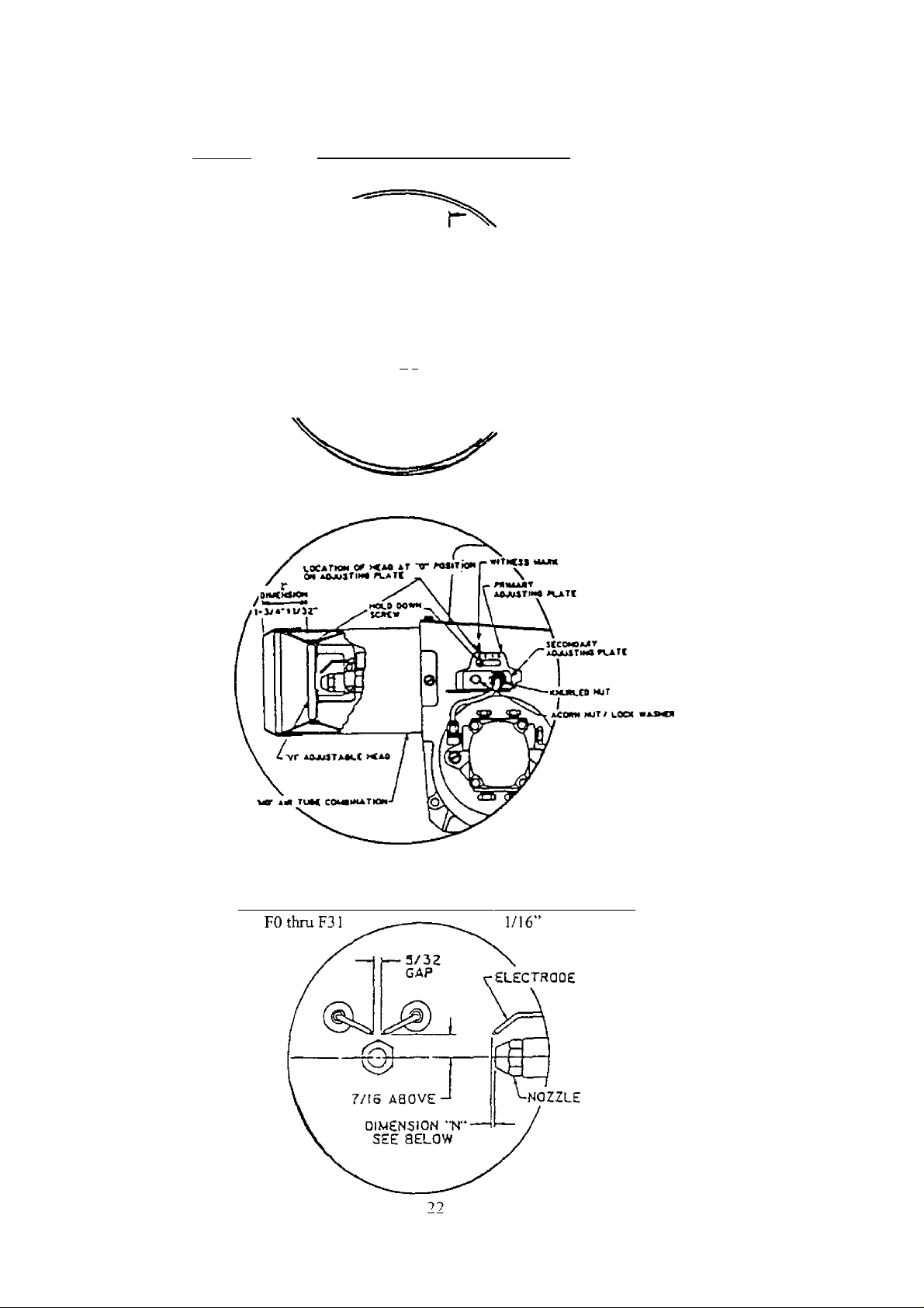
BECKETT AEG BURNER ELECTRODE ADJUSTMENTS VARIABLE (VI) HEADS
BOILER
MODEL
5EW
1—^—"^iiS
. rrc
LI Of VI HEAO-
DIMENSION “N” DIMENSION “H"
(electrode to nozzlel (head to nozzle)
1/16” 7/32” to 9/32”
01 WENS t ON "H"
^ SEE BELOW ^
5/32
'GAP-
L 3/16 ABOVE I ■ 7,"
■ELECTROOe
DIMENSION “N"
SEE BELOW
NOZZLE
Jl
BECKETT AFG VARIABLE (VI) HEAD ADJUSTMENTS AND SETTINGS
BECKETT AFG BURNER ELECTRODE ADJUSTMENTS F- HEADS
Burner F-Head Model DIMENSION “N” (head to nozzle)
Page 25
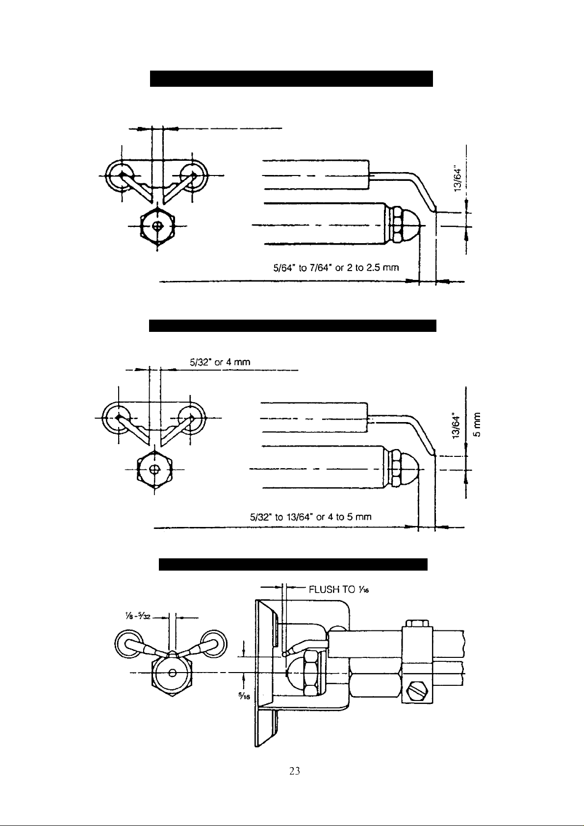
RIELLO 40-F5 BURNER ELECTRODE ADJUSTMENTS
5/32" - 4 mm
RIELLO 40 F10 BURNER ELECTRODE ADJUSTMENTS
£
CARLIN E-Z BURNER ELECTRODE ADJUSTMENTS
Page 26

CHECKING AND ADJUSTING CONTROLS
A boiler using a tankless coil is configured with a Honeywell L8124C Combination Hi/Low Limit Aquastat
Relay (refer back to the SYSTEM PIPING section for more details). A boiler not using a tankless coil is
configured with a Honeywell L8148A Hi Limit Aquastat Relay. Instructions for the control provided are
included with the boiler.
IMPORTANT - You or your installer must follow these instructions carefully.
ADJUST OPERATING CONTROLS: For both aqaustats, use the following settings for the first
adjustment;
High Limit: Baseboard and Convectors - 200°F
Standing Radiators - 180°F
Low Limit (when used) - 140°F (increase if hotter domestic water is required, but low limit set
point must be at least 20°F less than the high limit set point)
Differential (when used) - 10°F
ADJUST THERMOSTAT HEAT ANTICIPATOR TO: 0.2 AMPS
CHECK THERMOSTAT OPERATION: The thermostat location has an important effect on the operation
of the boiler system. Be sure to FOLLOW THE INSTRUCTIONS included with your thermostat. Typically
the thermostat is located about five feet above the floor on an inside wall. The thermostat should be located
to sense average room temperature, so avoid the following:
DEAD SPOTS - behind doors, comers, and alcoves
HOT SPOTS - concealed pipes, fireplace, TV sets, radios, lamps, direct sunlight, kitchens
COLD SPOTS - concealed pipes or ducts, drafty stairwells or door ways, unheated room or wall of
an unheated room
When the temperature on the thermostat is set above the indicated thermostat temperature, the boiler’s burner
should start. Make certain: once the room temperature reaches the selected temperature setting, the
thermostat should turn the boiler’s burner off, and once the room temperature falls a few degrees the boiler
starts operating again. Do not start the burner unless all cleanout doors are secured in place.
Do not attempt to start the burner when excess oil has accumulated, when the
unit is full of vapor, or when the combustion chamber is very hot.
24
Page 27

MAINTENANCE
ANUALLY: To assure trouble-free operation, it is recommended that the flue passages, combustion
chamber area (target wall, fire door insulation, durablanket), burner adjustment, operation of the controls,
and boiler seals (fire door gasket or silicone seal, cast iron sectional seals, flue collector) be checked once
each year by a competent Service Technician. Before the start of each heating season (or whenever the
system has been shut down for extended periods of time) recheck the whole system for water, oil, and vent
piping leaks. Replace or patch any leaks or seals that are faulty.
VENT PIPE: Visually inspect the entire venting system once a month for any signs of leakage,
deterioration, or soot build up. If the vent pipe shows any signs of leaking or deterioration, replace it
immediately. If it shows any signs of soot build up, clean the vent pipe and have the burner settings and
combustion checked by a competent professional.
RELIEF VALVE: This valve should open automatically when the system pressure exceeds the pressure
rating (usually 30 psi) of the relief valve. Should the valve ever fail to open under this condition, shut down
the system. Drain the system until system pressure is reduced below the relief valve pressure rating. Then
contact a competent Service Technician to replace the valve and inspect the heating system and determine
the cause, as this problem may indicate an equipment malfunction. The relief valve should be tested monthly
during the heating season. Prior to testing, make certain a discharge pipe is properly connected to the valve
outlet and arranged so as to contain and safely dispose of boiler discharge. Hold the trip lever fully open for
at least five seconds in order to flush free any sediment that may lodge on the valve seat. Then permit the
valve to snap shut. Refer to the valve manufacturer’s instructions packaged with the valve for more details.
CONVENTIONAL EXPANSION TANK: As noted in the EQUIPMENT AND OPTIONAL
ACCESSORIES section, this tank may become water logged or may receive an excess of air. Frequent
automatic opening of the relief valve indicates water logging. A high boiler temperature accompanied by
unusually low radiation unit temperature (and “knocking” noises) indicates excess air in the tank. To correct
either condition, close the valve between the boiler and the tank. Drain the tank until empty. Check all the
tank plugs and fittings, tighten as necessary. Open the valve between the boiler and tank. Water will rise to
the normal height in the tank if the system has an automatic fill valve, otherwise manually refill the system.
DIAPHRAGM EXPANSION TANK: As noted in the EQUIPMENT AND OPTIONAL ACCESSORIES
section, this tank may become water logged. Frequent automatic opening of the relief valve indicates water
logging. A high boiler temperature accompanied by unusually low radiation unit temperature (and
“knocking” noises) indicates excess air in the tank. To correct this condition, replace the diaphragm
expansion tank.
WATER SYSTEM: If the system is to remain out of service during freezing weather, always drain it
completely (water left in to freeze will crack the pipes and/or boiler).
TANKLESS COIL (OR COVER PLATE) GASKET: This gasket should be checked at least twice a year
for leakage and replaced if necessary. If the gasket is replaced, make sure that when the coil plate (or cover
plate) is reattached that the ten nuts are torqued in an alternating pattern to ensure equal force is applied to
the entire gasket creating a good seal. The nuts should be torqued such that the gasket does not squeeze out
from behind the plate.
OIL BURNER: Oil burner maintenance is listed in this manual under OPERATING THE BOILER.
Never burn garbage or paper in the unit, and
never leave combustible material around it.
25
Page 28
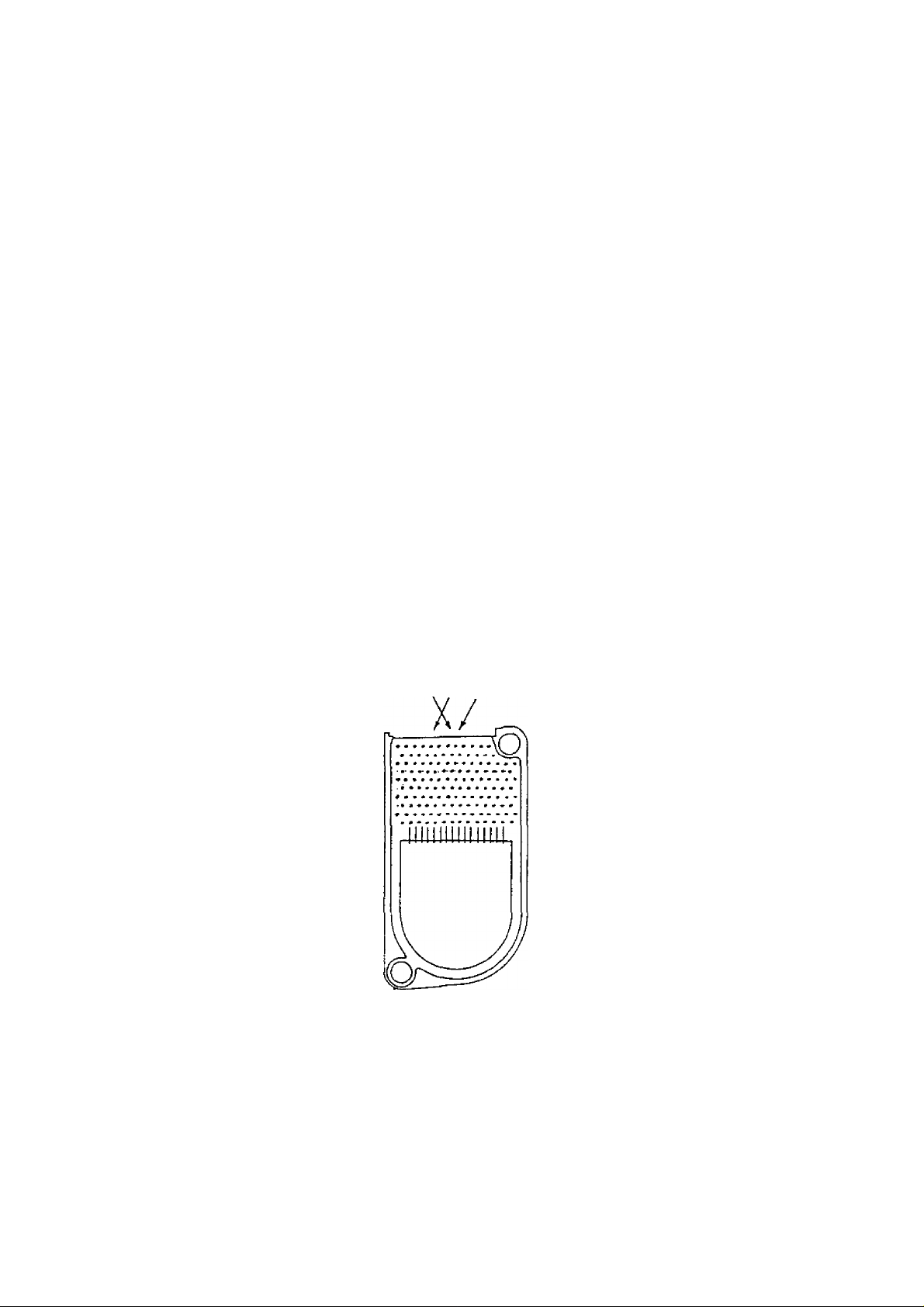
OIL BOILER / BURNER CLEANING INSTRUCTIONS
OIL BOILER CLEANING;
1. Shut off all electrical power to the boiler / burner and shut off fuel oil supply.
2. Remove the vent pipe from the top of the boiler. Inspect the pipe and chimney for signs of corrosion and
deterioration. Clean out the base of the chimney. If the vent pipe shows any signs of corrosion or
deterioration, replace it immediately. If chimney damage or deterioration is discovered, contact a
competent professional.
3. Remove the top jacket panel screws (5), the brass wing nuts (2) holding the flue collector top, and then
the flue collector top. Inspect the gasket on the underside of the flue collector and replace as necessary.
Before beginning to clean the flue passageways, ensure that the combustion chamber blanket is covered,
4.
[f the blanket is not covered prior to cleaning, replace the blanket once cleaning is completed.
Now with access to the flue passageways, remove the soot from the fireside surfaces by brushing
5.
diagonally through the flue passages (see drawing below). Brushing can be made easier by cutting the
end of the flue brush off and inserting it into a drill. When brushing, care should be taken so as not to
damage the target wall with the flue brush.
6. Carefully vacuum the soot accumulations from the combustion chamber area, being particularly careful
to not damage any of the refractory or blanket insulation. To gain access to the combustion chamber first
double check that the shut off valve on the fuel oil line is closed and then disconnect the fuel oil line.
Then open the swing door by simply removing the whiz lock nut holding the door shut.
7. Now inspect the target wall, fire door refractory, and combustion chamber blanket (when included) for
cracking and deterioration. If there is any signs of cracking or deterioration, replace the refractory or
blanket before reassembling the burner / front plate.
8. Inspect the door’s braided gasket for wear and damage. Replaee when necessary with braided gasket of
the same material and size. See repairs parts section of this manual.
9. Now inspect and clean the oil burner.
IMPORTANT OPERATING AND MAINTENANCE REQUIREMENTS
KEEP YOUR BOILER AND THE AREA AROUND IT CLEAN
NEVER BURN REFUSE OR ANY M ATERIAL OTHER THAN THE SPECIFIED FUEL IN
YOUR BOILER
HAVE YOUR BOILER CHECKED EACH YEAR BY A QUALIFIED TECHNICIAN
26
Page 29

OIL BURNER CLEANING:
These are seneral instructions for cleanine an oil burner. For specifics, consult the burner
manufacturer’s instructions.
1. Make sure all electrical power to the boiler / burner and the fuel supply to the burner are shut off.
2. With the swing door open, clean any soot accumulations from the end of the burner and if applicable
burner head.
Remove the burner drawer assembly, clean the electrodes and then reset the electrode spark gap per the
3.
manufacturer’s recommendations. Refer back to the section in this manual on OPERATING THE
BOILER - Nozzles and Electrodes.
Replace the oil nozzle with the exact same size and type recommended for use on this boiler.
4.
Reinstall the burner drawer assembly making sure the head location (and size if applicable) are per the
5.
manufacturer’s recommendations. If the burner being used has a damaged head, replace the head with
the exact same head recommended for use on this boiler.
Inspect and clean the oil burner blower wheel.
6.
7.
Remove the oil pump cover and clean / replace the pump screen. Carefully reassemble ensuring the
pump cover makes a proper seal.
Securely fasten the swing door shut.
8.
9.
Replace the fuel filter (if applicable).
10. Reconnect the electrical and fuel supplies.
11. Fire the burner, checking for proper combustion using combustion test equipment and making
adjustments as necessary. Refer to the section in this manual on OPERATING THE BOILER - Final
Burner Adjustments.
12. Insure that all safety controls and operating controls are functioning properly.
27
Page 30

SERVICE HINTS
You may avoid inconvenience and service calls by checking these points before you call for service.
IF YOUR SYSTEM IS NOT HEATING OR NOT GIVING ENOUGH HEAT
Possible Cause
'rhermostat is not set correctly
Boiler or Burner may be dirty
Burner may not be firing at
proper rate
Burner may be short-cycling
No power to boiler
Controls out of adjustments
Radiators not heating
Circulating pump not running
Poor electrical contact.
What to do
Reset thermostat above room temperature.
Clean all flue passages and the vent pipe. Have burner cleaned and readjusted.
Check nozzle size if there is any doubt. Have burner adjusted.
Short-cycling (too frequent off and on) of burner will cause sooting. If boiler and/or
burner become dirty at frequent intervals, after correcting the “dirty condition" also
correct the aquastat control setting (or other cause of short- cycling).
Check thermostat heat anticipator and correct setting, if necessary, per instruction
sheet packaged with thermostat.
Check overcurrent protection. Check to be sure power supply circuit is “ON”.
Reset according to instructions packed with controls.
Open radiator vents to vent excess air. Check flow control valve (if used). It may be
in closed position.
Check relay operation.
Check all control terminals and wire joints.
1 IF BURNER IS NOISY . . .
Possible Cause
Oil burner fan wheel may be dirty
Draft regulator may be stuck
Possible Cause What to do
Air in the system
Possible Cause
Dirt on seat
Water logged expansion tank
HAVE YOUR SERVICE TECHNICIAN CHECK ANY PROBLEM YOU ARE UNABLE TO CORRECT.
What to do
Clean fan wheel with a stiff brush and cleaning solvent. Readjust oil burner.
Check to see if vane swings freely. Clean, if vane is stuck.
Open radiator vents to vent the air. Check expansion tank.
What to do
Open valve manually. Allow water to run and clear valve seat.
Drain tank, see instructions.
IF RADIATORS ARE NOISY ... |
RELIEF VALVE IS LEAKING ... |
28
Page 31
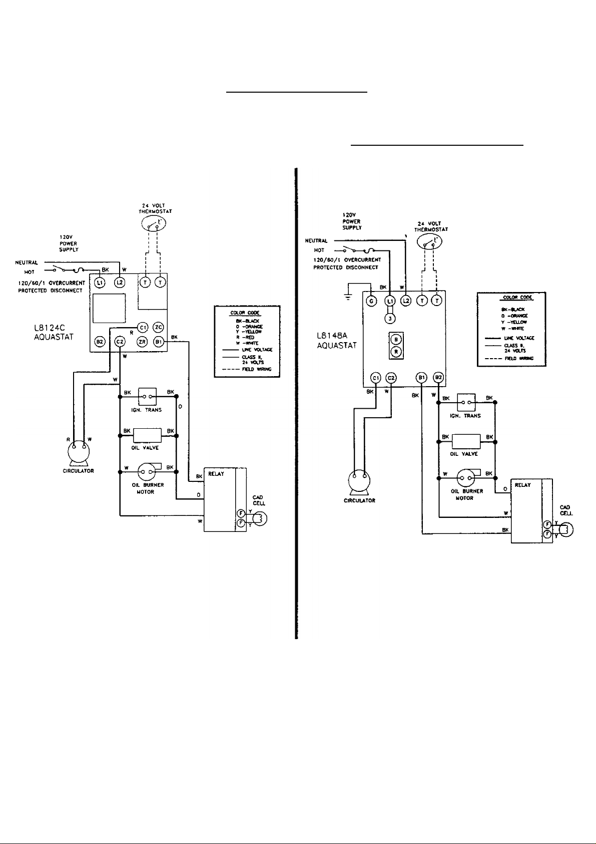
ELECTRICAL WIRING
BOILER WITH TANKLESS COIL AND
HONEYWELL L8124C AQUASTAT CONTROL
(BECKETT AEG BURNER SHOWN)
BOILER WITHOUT TANKLESS COIL
HONEYWELL L8I48A AQUASTAT CONTROL
(BECKETT AEG BURNER SHOWN)
Service Company:
Serviceman:
Address:
Telephone;
29
Page 32
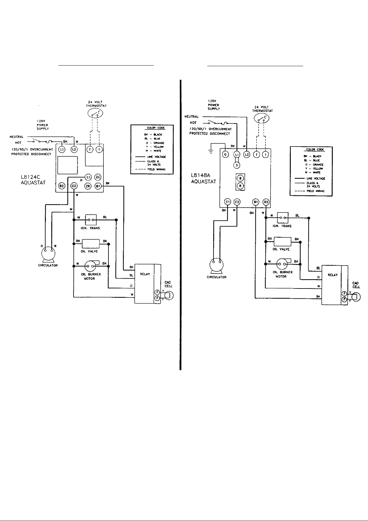
BOILER WITH TANKLESS COIL AND
HONEYWELL L8124C AQUASTAT CONTROL
__________
(CARLIN EZ BURNER SHOWN)
BOILER WITHOUT TANKLESS COIL
HONEYWELL L8148A AQUASTAT CONTROL
(CARLIN EZ BURNER SHOWN)
___________
Sen'ice Company:
Sen'iceman:
Address:
Telephone:
_____
________
______
Page 33
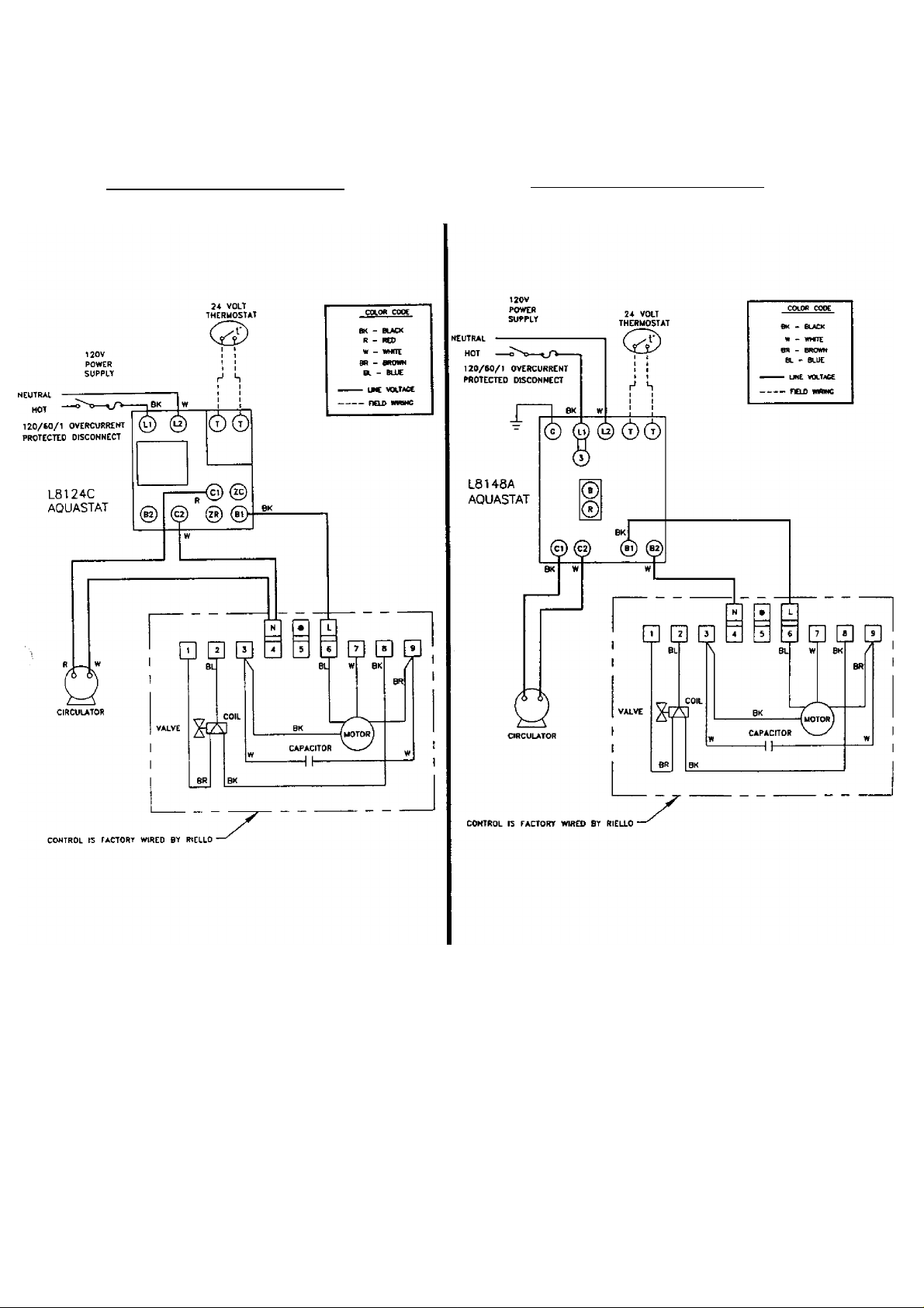
BOILER WITH TANKLESS COIL AND
HONEYWELL L8124C AQUASTAT CONTROL
(REELLO 40 BURNER SHOWN)
_________
BOILER WITHOUT TANKLESS COIL
HONEYWELL L8148A AQUASTAT CONTROL
(RIELLO 40 BURNER SHOWN)
_________
Service Company;
S erviceman:
Address:
_____
Telephone:
31
Page 34
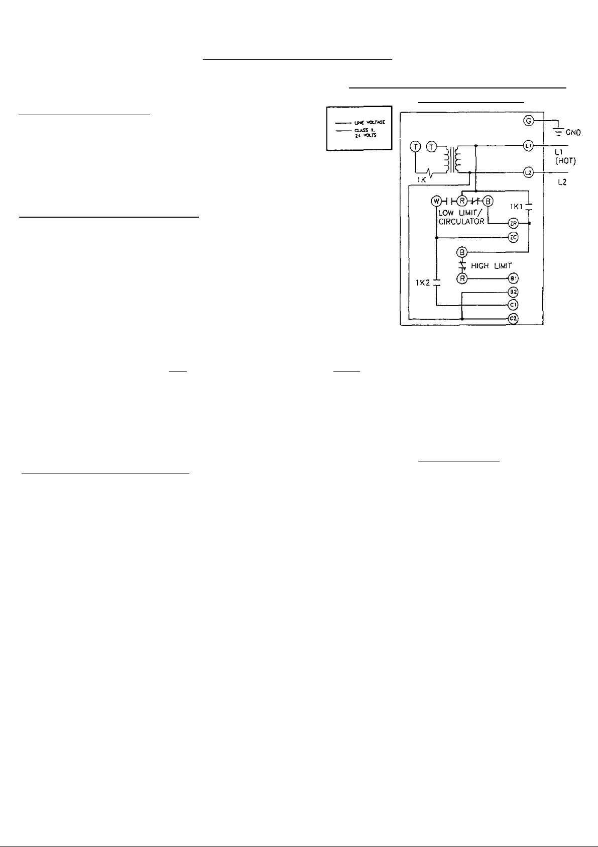
SEQUENCE OF OPERATION
BOILER WITH TANKLESS COIL:
INTERNAL WIRING FOR HONEYWELL
AQUASTAT L8124C
Aquastat high limit controller:
The aquastat control’s high limit contacts open and turn off the
burner when the boiler water temperature reaches the control’s
high limit set point. The high limit contacts automatically reset
after the boiler water temperature drops past the set point by 10°F,
which is a fixed'differential.
Aquastat low limit and circulator control:
With the adjustable differential at the minimum setting of 10°F;
• On a boiler water temperature rise above the low limit set point,
the burner circuit contacts (RB) break and the circulator circuit
contacts (RW) make.
• On a boiler water temperature drop of 10“F below the low limit
set point, the RB contacts make and the RW contacts break.
With the adjustable differential setting greater than 10°F:
• When the boiler water temperature is at (or below) the low limit set point, the RB contacts make and fire the
burner and the RW contacts break leaving the circulator off. The burner will fire until the boiler water temperature
reaches the low limit set point plus the adjustable differential setting minus 10°F. At this point the RB contacts break
stopping the burner and the RW contacts make. With no call for space heating, operating in this way keeps the circulator
off and allows the boiler to give preference to the domestic water heating requirements. Example: Consider the boiler
water temperature drops to 150°F with the low limit set at 160°F and the differential is set at 15°F. The burner will
begin to fire. When the aquastat probe senses a boiler water temperature of 165°F (15°F - 10°F = 5°F, then 160°F
+5°F = 165°F) the RB contacts break and the RW contacts make.
When the boiler vrater temperature rises above the low limit / adjustable differential setting and the thermostat
controls call for domestic space heating. The sequence of operation for the burner and circulator is as follows:
1. Thermostat calls for heat, completing circuit between terminals T & T on the aquastat controller, energizing the IK relay
coil.
2. With the IK relay coil energized, contacts IKl and 1K2 are closed. Terminal B1 is energized, providing power to the oil
burner primary control. This, in turn, powers the ignition coil and burner motor.
3. With the primary control energized, the burner operation starts and remains running as long as the cad cell senses flame.
In the event of flame failure or the flame is not fully proven within the trial for ignition period, the primary control will
lockout and open the burner circuit. This will require a manual startup of the burner.
4. As long as flame is proven through the cad cell relay, the burner will remain on until the circuit is interrupted by the
boiler water temperature reaching the aquastat’s high limit setting (opening high limit contacts RB), or the thermostat is
satisfied breaking the T-T circuit.
5. Circulator pump is powered through terminal Cl and will run when boiler water temperature is above the low limit
setting and there is a call for heat from the thermostat. If the boiler water temperature reaches the aquastat’s high limit
setting and high limit contact RB is de-energized, the burner stops but the circulator pump will continue to run, as long
as, the thermostat calls for heat.
6. Whenever the boiler water temperature reaches the aquastat’s high limit setting, the high limit contact RB is de-energized
shutting the burner off. Then the boiler water temperature must fail 10°F below the aquastat’s high limit setting for the
high limit contacts RB to close and the burner to be energized.
7. When the thermostat is satisfied, the call for domestic space heating is ended. Relay coil IK is de-energized, opening
1KI and 1K2 contacts. Both the burner and circulator pump operation stop.
NOTE: High limit setting must be a minimum of 20°F higher than the tow limit settinr
Page 35
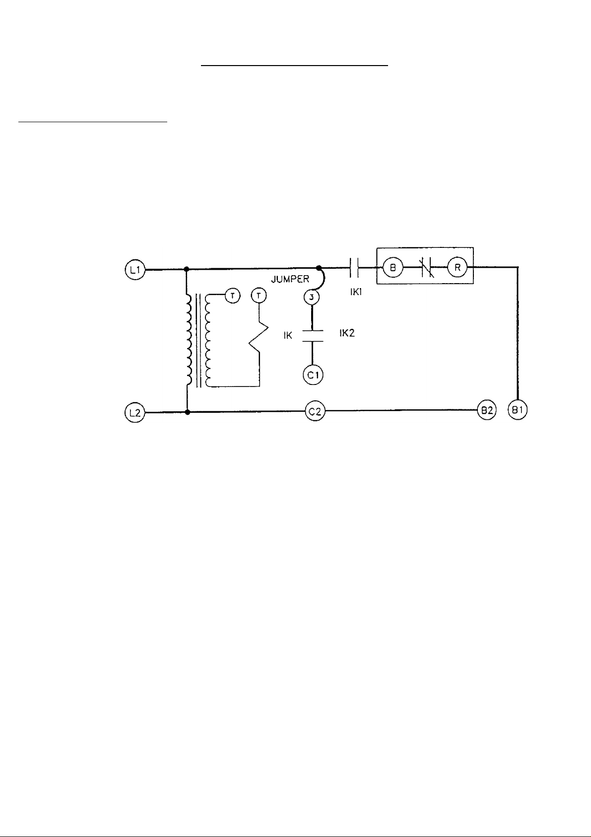
SEQUENCE OF OPERATION
BOILER LESS TANKLESS COIL:
Aguastat high limit controller:
The aquastat control’s high limit contacts open and turn off the burner when the boiler water temperature reaches
the control’s high limit set point. The high limit contacts automatically reset after the boiler water temperature
drops past the set point by 10°F, which is a fixed differential.
INTERNAL WIRING FOR HONEYWELL AQUASTAT L8148A
UHE VOLTAGE
CLASS d.
2+ VOLTS
When the thermostat controls call for domestic space heating. The sequence of operation for the burner
and circulator is as follows:
1. Thermostat calls for heat, completing circuit between terminals T & T on the aquastat controller, energizing the
IK relay coil.
2. With the IK relay coil energized, contacts IKl and 1K2 are closed. Terminals Cl and C2 are energized
providing power to the circulator. Terminal B1 is energized, providing power to the oil burner primary control.
This, in turn, powers the ignition coil and burner motor.
3. With the primary control energized, the burner operation starts and remains running as long as the cad cell
senses flame. In the event of flame failure or the flame is not fully proven within the trial for ignition period,
the primary control will lockout and open the burner circuit. This will require a manual startup of the burner.
4. As long as flame is proven through the cad cell relay, the burner will remain on until the circuit is interrupted
by the boiler water temperature reaching the aquastat’s high limit setting {opening high limit contacts BR), or
the thermostat is satisfied breaking the T-T circuit.
5. If the boiler water temperature reaches the aquastat’s high limit setting, the high limit contact BR is de
energized turning the burner off. However, the circulator pump will continue to run, as long as, the thermostat
calls for heat.
6. After the high limit contact BR is de-energized, the boiler water temperature must fall 10°F below the
aquastat’s high limit setting for the high limit contacts BR to close and energize the burner.
7. When the thermostat is satisfied, the call for domestic space heating is ended. Relay coil 1K is de-energized,
opening IKl and 1K2 contacts. Both the burner and circulator pump operation stop.
33
Page 36

Nores:
ccvti rat TOH.EH1 «iTMour rjw(U2s can. «jr swm
I I/*' ;oui3t HtJi muci ■'fflf owjM
5Z\ rao-r 3LACK 5iucaNC BuaaEH nor shqwh
jy' JOHCSive SEliLJ«r
REPAIR PARTS
ITEM
1 Water Boiler Back Section (EW-3) 403-00-008 403-00-008
2 Water Boiler Middle Section (EW-2)
Empire Water Front Section (EW-1) 403-00-006 403-00-006 403-00-006
3
4
5
6
7
8 Target Wall
DESCRIPTION
Cast Iron Machined Nipples 2"
1/4" Tie Rods
Tie Rod i/4"-20 Hex Head Nut
5/16" X 70-1/2" Braided Rope
9 1/2" thick Ourabianket
10 Collector Base (plus items 11,12,13)
11
Insulation Tape (plus items 10,12,13)
12
CollectorTop (plus items 10,11,13)
13 8/32" Brass Wing Nut
3EW 4EW
SEW
403-00-008
403-00-007 403-00-007
403-00-007
433-00-976 433-00-976 433-00-976
146-05-002 146-05-051 146-05-053
146-95-041 146-95-041 146-95-041
433-00-955 433-00-955 433-00-955
146-19-003 146-19-003 146-19-003
146-30-031 146-30-031
425-00-279
425-00-280 425-00-281
146-30-031
425-00-279 425-00-280 425-00-281
425-00-279
425-00-230 425-00-281
137-04-007 137-04-007 137-04-007
14 ffl4 X 3/4" Hex Washer Head Screw 146-95-070 146-95-070 146-95-070
15 Coil Housing Gasket
16 3.7 GPM Tankless Coil
17 Coii Housing Cover Plate (not shown)
Slainless Steel 3/8'-16 x 1-1/2" Stud
18
Stainless Steel 3/8" Flat Washer
19
20 Stainless Steel 3/8" Top Lock Nut
21 1-1/4" Solid Plug (not shown)
Black Silicone Sealant (not shown)
22
146-93-064 146-93-064 146-93-064
146-27-020 146-27-020 146-27-020
146-19-001 146-19-001 146-19-001
146-95-113
146-95-113 146-95-113
146-95-114 146-95-114 146-95-114
146-95-115 146-95-115
146-93-126
146-93-126
146-95-115
145-93-126
146-06-020 146-06-020 146-06-020
Note: item quantities marked XXX vary depending upon the nurnber of sections.
Four cast iron nipples for first middle replacement section and two for each
additional section. Durablanket is sold as one oversized piece to be cut to
fit the appropriate boiler-- 6“x12" (3EW), 9’x20" (4EW). 12"x20" (5EW),
Black silicone sealant is sold in 10.3 ounce cartridges.
__________
34
Page 37
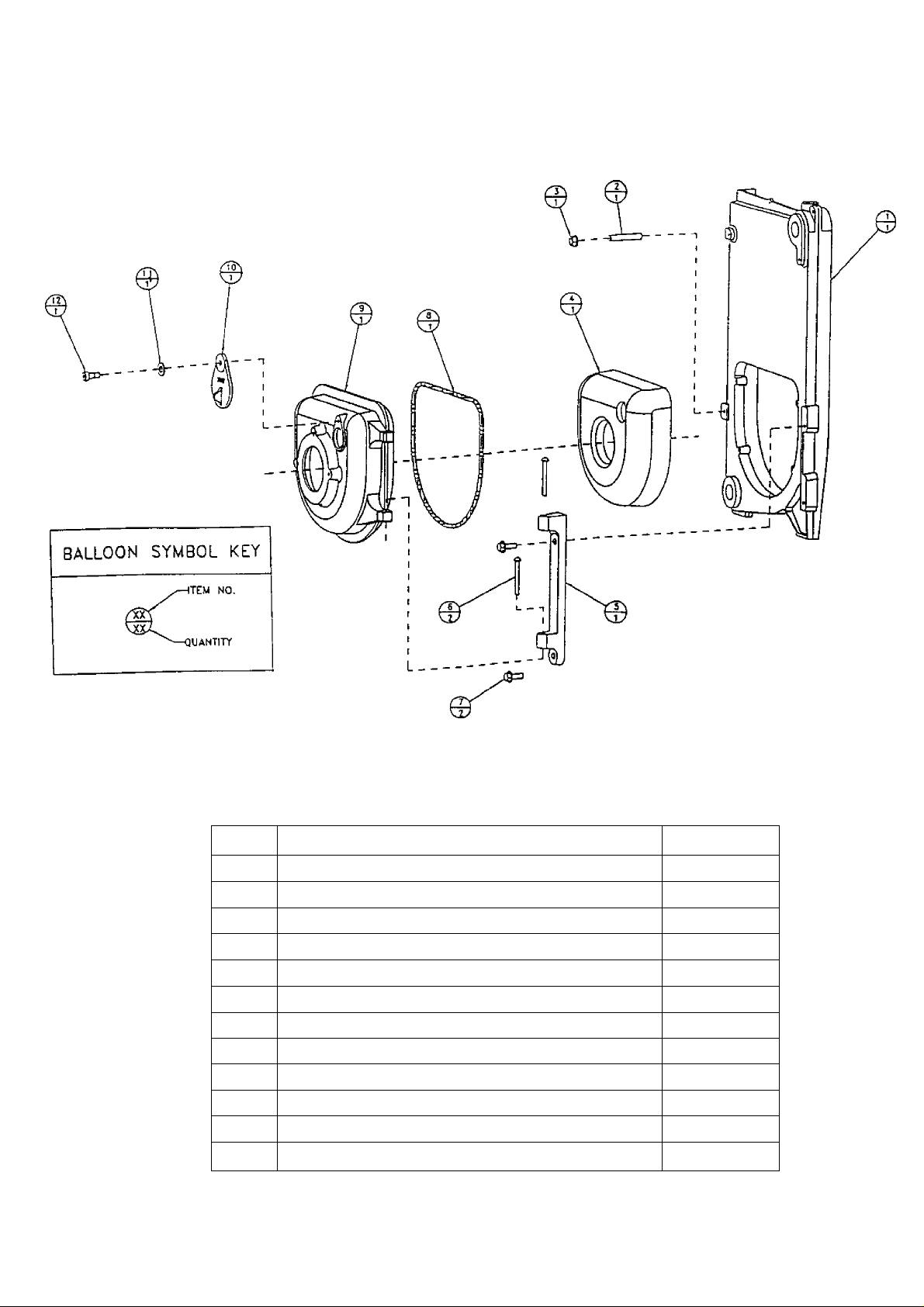
REPAIR PARTS
ITEM
1
2
3
4
5
Empire Water Front Section (EW-1)
DESCRIPTION
3/8’M6x 2-1/4" stud
3/8" Whiziock Nut
Swing Door Insulation
Swing Door Hinge
6 1/4" X 2" Round Head Rivet
7
8
9
10
3/8" X 1" Hex Head Serrated Flange Bolt
3/8" x 48" Fiberfrax Round Braid
Swing Door
Obsen/ation Door
11 5/16" Lock Washer
12 3/8" X 3/8" Shoulder Bolt 5/16"-18 Thread
35
Part#
403-00-006
146-95-125
146-95-126
146-14-014
403-00-010
146-95-121
146-95-124
433-00-905
403-00-009
403-00-014
146-95-123
146-95-122
Page 38

REPAIR PARTS
ITEM
1
2
3
4
5
6
7
8
9
XX
DESCRIPTION
Right Side jacket Panel
Back Jacket Panel
Top Jacket Panel
Left Side jacket Panel
Upper Front Jacket Panel
5/16" Acorn Nut 146-95-042
#10 X 1/2" Jacket Screw 146-95-074
Stand Off 146-95-103 146-95-103
Lower Front Jacket Panel (boiler w/ swing door)
Complete Jacket for Boiler with Swing Door
36
3EW
425-00-244
425-00-269
425-00-254
425-00-264
425-00-267
425-00-268
425-00-289
4EW
425-00-245 425-00-246
425-00-269
425-00-255
425-00-265
425-00-267
146-95-042
146-95-074
425-00-268
425-00-290 425-00-291
SEW
425-00-269
425-00-256
425-00-266
425-00-267
146-95-042
146-95-074
146-95-103
425-00-268
Page 39
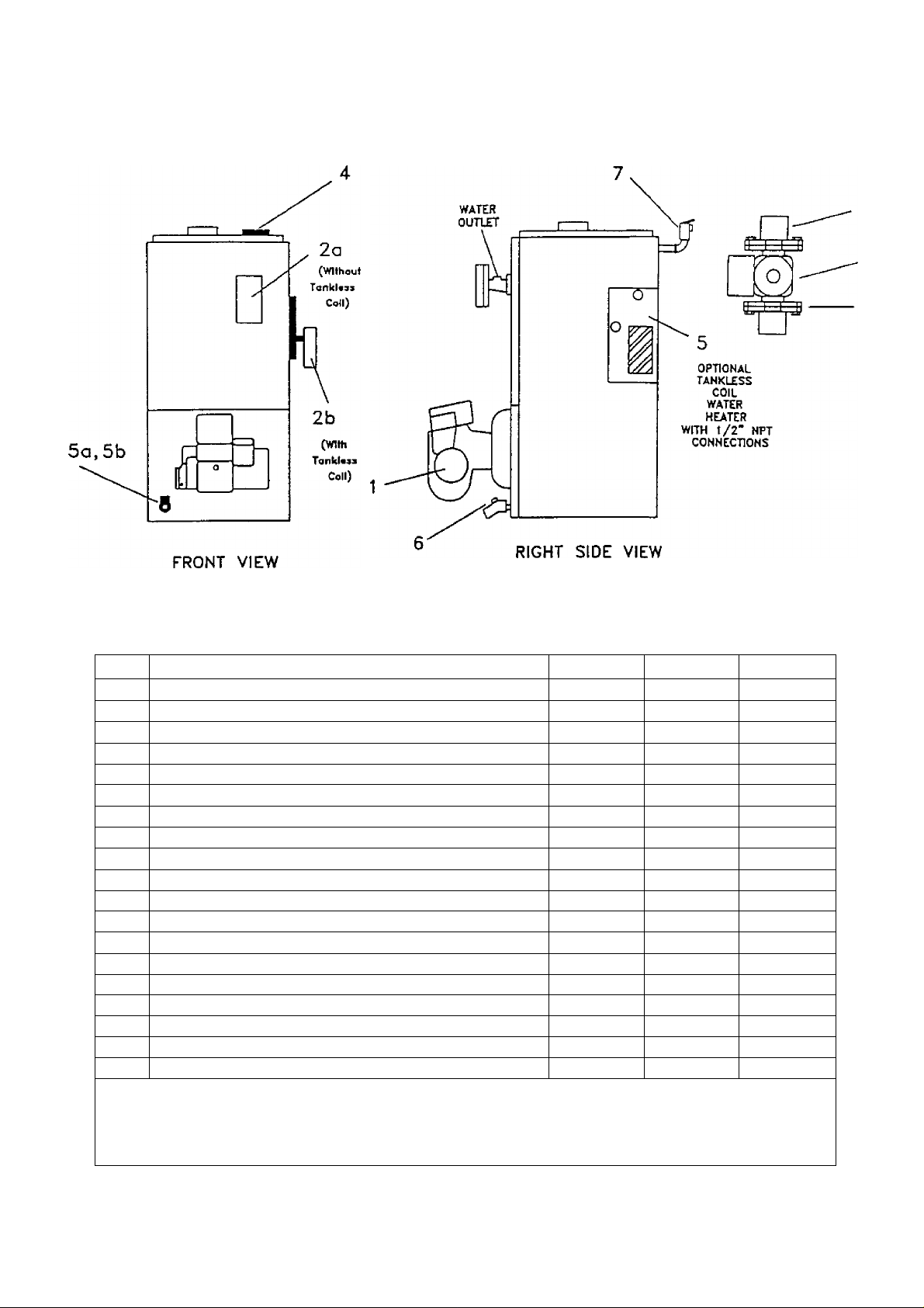
REPAIR PARTS
3b
3a
3c
ITEM DESCRIPTION
3EW 4EW
1 Beckett AFG F-Head Oil Burner 146-19-007 146-19-008
1
—
Beckett AFG Variable Head Oil Burner
Beckett AFG F-Head Low Fire Kit (0.65 gph) 433-00-015
Beckett AFG F-Head Low Fire Kit (0.90 gph) 433-00-016
1
Carlin EZ-IOil Burner
146-19-005 146-19-005 146-19-005
1 Carlin EZ-2 Oil Burner
1
1 Riello 40 F10 Oil Burner
2a L8148A-1124 Aquastat Control ( no tankless coil)
2b L8124C-1094 Aquastat Control (with tankless coil) 146-62-022
Riello 40 F5 Oil Burner 146-19-010 146-19-010 146-19-010
—
433-00-521
433-00-521 433-00-521
146-62-022 146-62-022
3a Taco 007 Circulator 146-26-047 146-26-047
3b
3c
1-1/4" Isolation Valves
Taco Circulator Gaskets
146-26-048 146-26-048
146-26-050 146-26-050 146-26-050
Taco 007 Circulator with Gaskets 433-00-047 433-00-047
4 Temperature / Pressure Gauge 2" Stem
5a
5b
6
7
Note;
Beckett AFG F-Head low fire kits include: static plate, burner head, and oil nozzle.
1-1/4" X 2-1/2" Pipe Nipple
1-1/4" X 3/4" X 1-1/4" Reducing Tee 146-93-049 146-93-049
3/4" Drain Valve
3/4" Relief Valve
146-23-003 146-23-003 146-23-003
146-07-044 146-07-044 146-07-044
146-22-000 146-22-000
146-22-011
146-22-011 146-22-011
The temperature / pressure gauge connects to the boiler using a 3/4" x 1/4" bushing.
The relief valve connects to the boiler using a 3/4" x 2" nipple and a 3/4" street elbow.
5EW
146-19-009
146-19-006
146-19-011
146-26-047
146-26-048
433-00-047
146-93-049
146-22-000
37
Page 40

BECKETT OIL BURNER. NOZZLE. AND AIR SETTINGS
BOILER
MODEL OIL NOZZLE
3EW.65*
3EW.75
3EW1.00 0.85-70“B
4EW.90
4EW1.25
4EW1.50
5EW1.20
5EW1.75
5EW2.00
*To fire the SEW.65 on rate, the oil pressure must be increased to 175 psig.
All Beckett oil burners for the EW boiler are factory preset at 140 psig.
DELEVAN FIRING HEAD-ADJ.
RATE (gph) OR SETTING
0.50-80°B 0.65
0.65-70“B 0.75
1.00 F3- 1 1/8
0.75-80°A 0.90 F3 - 1 1/8
1.00-80°A 1.25
1.25-80°A 1.50 F6 - 1 1/8
1.00-60°B 1.20 0
1.50-45“B
1.65-60-B 2.00 4 NO
1.75 2 NO
FO - 1 1/8 YES
F3 - 1 1/8 YES
F6 - 1 1/8 NO
LOW FIRE AIR STATIC OIL
BAFFLE
CARLIN OIL BURNER. NOZZLE. AND AIR SETTINGS
BOILER“
MODEL
3EW.65
3EW.75
3EW1.00
4EW.90 0.75-60°B 0.90
4EW1.25
4EW1.50
5EW1.20
5EW1.75
5EW2.00
DELEVAN
OIL NOZZLE RATE (gph)
0.55-70°B 0.65 0.50
0.65-60°B 0.75 0.60 / 0.65 0.60
0.85-60°B 1.00 0.85/1.00
1.00-60°B 1.25 0.85 /1.00 0.90
1.25-60°B 1.50 1.10/1.25
1.00-60°B 1.20
1.50-60°B 1.75 1.50
1.65-70°B 2.00
FIRING HEAD AIR BAND
SETTING SET POINT
0.75 0.75
0.85/1.00 0.90
1.65/1.75 1.95
SHUTTER/BAND
10/0 3-5/8
10/0 3-1/2 AFG F-HEAD
NO
NO
NO 10/2 3-3/8 AFG F-HEAD
NO 10/1.5 2-3/4 AFG 50 MD
10/2 3-1/2
8/0 3-1/2
10/0 3-3/8
10/4 2-3/4
10/5 2-3/4 AFG 50 MD
PLATE BURNER
AFG F-HEAD
AFG F-HEAD
AFG F-HEAD
AFG F-HEAD
AFG 50 MD
CARLIN
BURNER*
0.52
0.80 EZ-1 HP
1.25 EZ-1 HP
1.65 EZ-2 HP
EZ-1 HP
EZ-1 HP
EZ-1 HP
EZ-1 HP
EZ-1 HP
EZ-2 HP
'All Carlin EZ-1 HP and EZ-2 HP oil burners are factory preset at 150 psig.
RIELLO 40 OIL BURNER. NOZZLE. AND AIR SETTINGS
BOILER DELEVAN FIRING
MODEL OIL NOZZLE FÎATE (gph)
3EW.65
3EW.75 0.65-70°W 0.75
3EW1.00
4EW.90
4EW1.25 1.00-70°W 1.25
4EW1.50 1.25-70°W 1.50
5EW1.20
5EW1.75
5EW2.00
'All Riello 40 F5 and FI0 oil burners are factory preset at 145 psig.
0.50-70°W 0.65 0.5 / 2.0
0.85-70°W 1.00
0.75-70°W 0.90 1.5/2.6
1.00-70°W 1.20 2.5/3.5
1.50-70°W 1.75 2.0/3.8
i.zs-zo-w 2.00
TURBULATOR/AIR
SHUTTER SETTING (PSIG)*
2.0 / 2.2 150
2.0 / 3.2
2.5/3.8 170
4.0/7.0 175
2.5/4.1 155
OIL PRESSURE
155 F5
170
160 F5
150 F5
155 F10
NOTE: All burners use an insertion depth of 2-1/4" and fired at a
overfire draft of -0.02 inches w.c. The burner settings provided
are intended for initial start up only. Final adjustment must be made
using combustion test instruments.
____________________________
RIELLO 40
BURNER MODEL
F5
F5
F5
F5
F10
38
Page 41

KGnmarG
Oil-Fired
Hot Water
Owner's Manual
MODEL NO.
3EW.65
3EW.7S
3EW1:00
4EW.90
4EW1-25
4EWf.50
5EW1,20
5EW1.75
5EW2.00
Boiler
Now that you have purchased your Boiler should a need
ever exist for repair parts or service, simoly contaci any
Sears Service Center Be sum to provide all ijertm-jMi fards
when you call or visit
The n”iodel number of your Boiler will be found on rh^ n udei
plate on the side of the Boiler
WHEN ORDERING REPAIR PARTS, ALWAYS GIVE ^HE
FOLLOWING INFORMATION
•PART NUMBER
•MODEL NUMBER
All parts listed may be ordered from anv Sears Service
Center
• PART DESCRIPTION
• NAME OF ITEM
If the parts you need are not slocked locally, your order
will be electronically transmitted to a Sears Repair Parts
Distribution Center for handling
HOW TO OROBR
REPAIR PARTS
TELL SEARS YOU
WANT IT INSTALLED
THEN RELAX
When Sears arranges the installation, you can be sure tfie
|0b IS done right We will arrange for professional
workmanship and well take care of tfif^ entire projert
What's more during installation you yet insured protection
against property darriage and atso against accidents
to workmen All you havr^ to do is talk [o your nearest Sears
store today tor detailo:.! infr)rmatiun
Sears, Roebuck and Co., Hoffman Estates, tL 60179 U.S.A.
 Loading...