


Kenmore 580.75119500 Owner's Manual
Owner's Manual
Manual del Propietario
®
THROUGH-THE-WALLAIRCONDITIONER
ACONDICIONADODEAIREA TRAVESDEPARED
Model, Modelo 580.75119
Sears, Roebuck and Co., Hoffman Estates, IL 60179 U.S.A.
www.sears.com
TABLE OF CONTENTS ........................2
Features ................................................. 13
WARRANTY ..............................................2
SAFETY .....................................................3
Important Safety Instructions ...................... 3
ELECTRICAL REQUIREMENTS .......4
INSTALLATION ........................................5
Installation Requirements ......................... 5
Installation ................................................ 6
Procedure A ............................................. 7
Procedure B ............................................. 8
Procedure C ........................................... 10
OPERATION ...........................................12
How and Why ......................................... 12
Normal Sounds ...................................... 12
Capacity and Running Time ................... 12
Using the Air Conditioner ....................... 13
Air Conditioner Features ........................ 14
MAINTENANCE .....................................16
Air Filter Cleaning ................................... 16
Air Conditioner Cleaning ........................ 16
How to Remove the Front Grille ............. 16
How to Replace the Front Grille ............. 16
TROUBLESHOOTING .........................17
Before Calling for Service ...................... 17
ESPANOL ................................................18
MASTER PROTECTION
AGREEMENTS ......................................35
SERVICE NUMBERS ............ Back Cover
FULL ONE YEAR WARRANTY ON
THROUGH-THE-WALL AIR CONDITIONER
For one year from the date of purchase, when this
air conditioner is operated and maintained for
normal room cooling according to instructions in this
owner's manual, Sears will repair this air
conditioner, free of charge, if defective in material or
workmanship.
WARRANTY SERVICE IS AVAILABLE BY
CONTACTING SEARS SERVICE AT 1-800-4-
MY-HOME ®.
This warranty applies only while this product is in
use in the United States.
This warranty gives you specific legal rights, and
you may also have other rights which vary from
state to state.
Sears, Roebuck and Co., D/817WA,
Hoffman Estates, IL 60179 U.S.A.
-2-
IMPORTANT SAFETY INSTRUCTIONS
The safety instructions below will tell you how to use your room air conditioner to avoid harm to yourself or
damage to your ROOM AIR CONDITIONER.
V!_W:_;t_II_[_FOR YOUR SAFETY
Do not store or use gasoline or other flammable
vapors and liquids in the vicinity of this or any other
appliance. Read product labels for flammability and
other warnings.
PREVENT ACCIDENTS
To reduce the risk of fire, electrical shock, or injury
to persons when using your air conditioner, follow
basic precautions, including the following:
• Be sure the electrical service is adequate for the
model you have chosen.
• If the air conditioner is to be installed in a window,
you will probably want to clean both sides of the
glass first. If the window is a triple-track type with a
screen panel included, you may want to remove
the screen completely before installation.
• Be sure the air conditioner has been securely and
correctly installed according to the instructions in
this manual.
Save this manual and installation instructions for
possible future use in removing or reinstalling this
unit.
• Use gloves when handling the air conditioner.
Be careful to avoid cuts from sharp metal fins on
front and rear coils.
V!_W,.1;i_ll_[dELECTRICAL INFORMATION
The complete electrical rating of your new room air
conditioner is stated on the serial plate. Refer to the
rating when checking the electrical requirements.
• Be sure the air conditioner is properly grounded.
To minimize shock and fire hazards, proper
grounding is important. The power cord is
equipped with a three-prong grounding plug for
protection against shock hazards.
• Your air conditioner must be plugged into a
properly grounded wall receptacle. If the wall
receptacle you intend to use is not adequately
grounded or protected by a time delay fuse or
circuit breaker, have a qualified electrician install
the proper receptacle.
• Do not run air conditioner with packing sheet of
the back of the sleeve, and packing corner and
blue tape of the air conditioner. This could result in
mechanical damage within the air conditioner.
• Do not use an extension cord or an adapter
plug.
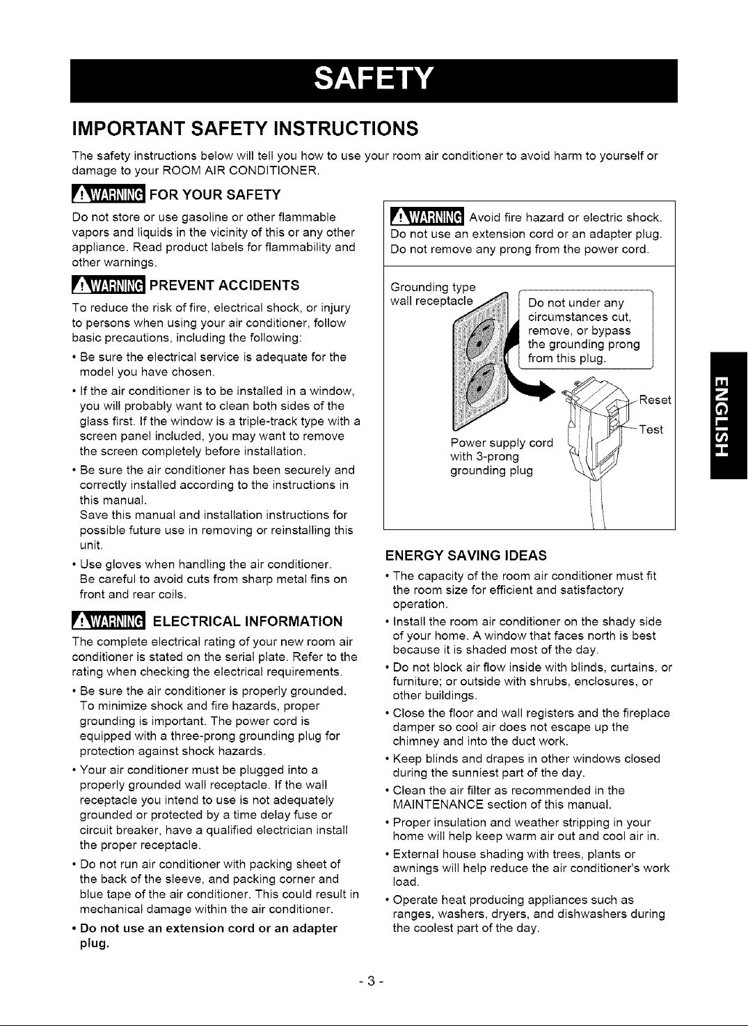
_ Avoid fire hazard or electric shock.
Do not use an extension cord or an adapter plug.
Do not remove any prong from the power cord.
Grounding type
wall receptacle
Do not under any
circumstances cut,
remove, or bypass
the grounding prong
from this plug.
Power supply cord
with 3-prong
grounding plug
ENERGY SAVING IDEAS
• The capacity of the room air conditioner must fit
the room size for efficient and satisfactory
operation.
• Install the room air conditioner on the shady side
of your home. A window that faces north is best
because it is shaded most of the day.
• Do not block air flow inside with blinds, curtains, or
furniture; or outside with shrubs, enclosures, or
other buildings.
• Close the floor and wall registers and the fireplace
damper so cool air does not escape up the
chimney and into the duct work.
• Keep blinds and drapes in other windows closed
during the sunniest part of the day.
• Clean the air filter as recommended in the
MAINTENANCE section of this manual.
• Proper insulation and weather stripping in your
home will help keep warm air out and cool air in.
• External house shading with trees, plants or
awnings will help reduce the air conditioner's work
load.
• Operate heat producing appliances such as
ranges, washers, dryers, and dishwashers during
the coolest part of the day.
-3-
OBSERVEALLLOCALCODESAND
ORDINANCES.
DONOT,UNDERANYCIRCUMSTANCES,
REMOVETHEPOWERSUPPLYCORD
GROUNDPRONG.
ELECTRICALGROUNDISREQUIREDON
THISAPPLIANCE.
208/230-volt60Hzand115-volt60Hz,AC
only,15Afusedandproperlygrounded
electrical supply is required. A time delay fuse
or time delay circuit breaker is recommended.
Use a dedicated circuit, serving only this
appliance.
DO NOT USE AN EXTENSION CORD.
RECOMMENDED GROUNDING METHOD
For your personal safety, this appliance must
be grounded. This appliance has a power
supply cord with a 3-prong grounding plug. To
minimize possible shock hazard, the cord must
be plugged into a mating grounding type wall
receptacle and grounded in accordance with
the National Electrical Code (ANSt/NFPA 70)
latest edition and all local codes and
ordinances. If a mating wall receptacle is not
available, it is the personal responsibility and
obligation of the customer to have a properly
grounded 3-prong wall receptacle installed by a
qualified electrician.
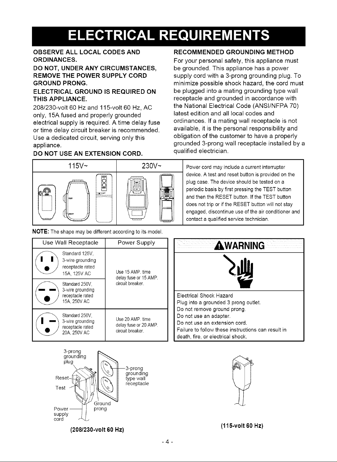
115V~ 230V~
NOTE:The shape may be different according to its model.
Use Wall Receptacle Power Supply
3-wire grounding
_) tandard 125V,
receptacle rated
15A, 125V AC
Standard 250V,
3-wire grounding
receptacle rated
15A,250V AC
Standard 250V,
3-wire grounding
receptacle rated
2OA,250V AC
Use t5 AMP. time
delayfuse or 15AMP.
circuit breaker.
Use 20AMP. time
delay fuse or 20AMP.
circuit breaker.
Power cord may include a current interrupter
device. A test and reset button is provided on the
plug case. The device should be tested on a
periodic basis by first pressing the TEST button
and then the RESET button. If the TEST button
does not trip or if the RESET button will not stay
engaged, discontinue use of the air conditioner and
contact a qualified service technician.
AWARNING
Electrical Shock Hazard
Plug into a grounded 3 prong outlet.
Do not remove ground prong.
Do not use an adapter.
Do not use an extension cord.
Failure to follow these instructions can result in
death, fire, or electrical shock.
3-prong
grounding
plug
Reset-
Test
supply
cord
(208/230-volt 60 Hz)
--3-prong
grounding
type wall
receptacle
Ground
prong
(115-volt 60 Hz)
-4-
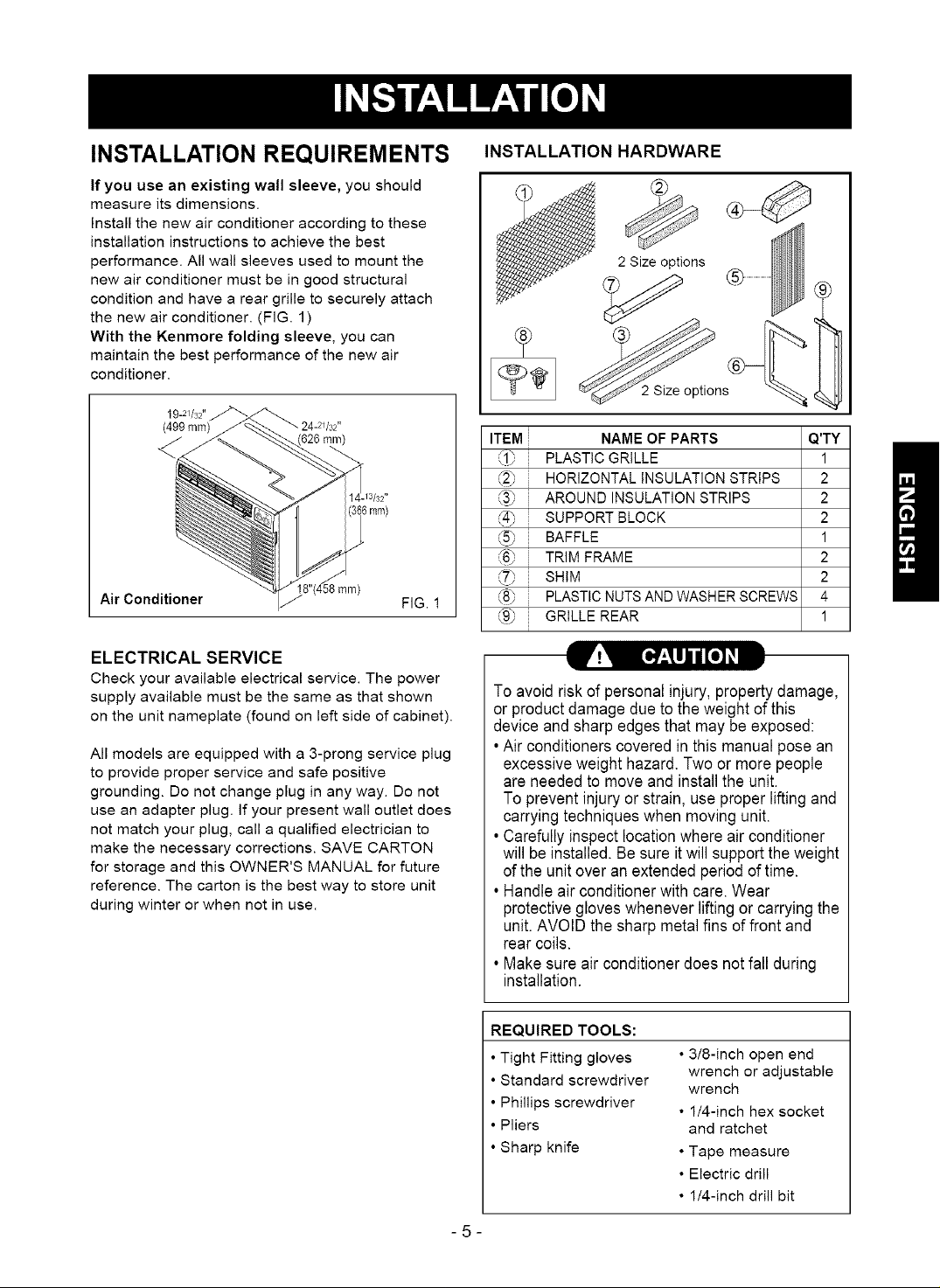
INSTALLATION REQUIREMENTS
If you use an existing wall sleeve, you should
measure its dimensions.
Install the new air conditioner according to these
installation instructions to achieve the best
performance. All wall sleeves used to mount the
new air conditioner must be in good structural
condition and have a rear grille to securely attach
the new air conditioner. (FIG. 1)
With the Kenmore folding sleeve, you can
maintain the best performance of the new air
conditioner.
19-2//32"
(499 ram) 24-2q32"
Air Conditioner
ELECTRICAL SERVICE
Check your available electrical service. The power
supply available must be the same as that shown
on the unit nameplate (found on left side of cabinet).
All models are equipped with a 3-prong service plug
to provide proper service and safe positive
grounding. Do not change plug in any way. Do not
use an adapter plug. If your present wall outlet does
not match your plug, call a qualified electrician to
make the necessary corrections. SAVE CARTON
for storage and this OWNER'S MANUAL for future
reference. The carton is the best way to store unit
during winter or when not in use.
(626 ram)
ram)
6ram)
FIG. !
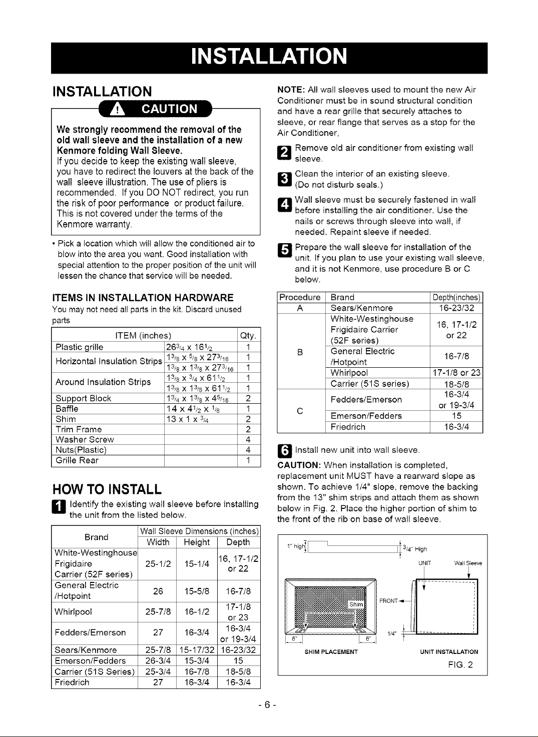
INSTALLATION HARDWARE
2 Size options
2 Size options
ITEM NAME OF PARTS Q'TY
_'1_ i PLASTIC GRILLE 1
i HORIZONTAL INSULATION STRIPS 2
i AROUND INSULATION STRIPS 2
SUPPORT BLOCK 2
::BAFFLE 1
@ i TRIM FRAME 2
i SHIM 2
{8_ i PLASTIC NUTS AND WASHER SCREWS 4
_B_ GRILLE REAR I
To avoid riskof personal injury, property damage,
or product damage due to the weight of this
device and sharp edges that may be exposed:
• Air conditioners covered in this manual pose an
excessiveweight hazard. Two or more people
are needed to move and install the unit.
To preventinjury or strain, use proper lifting and
carrying techniques when moving unit.
• Carefully inspectlocation where air conditioner
will beinstalled. Be sure it will support the weight
ofthe unitover anextended periodof time.
• Handle air conditioner with care. Wear
protective gloves whenever lifting or carryingthe
unit. AVOID the sharp metal fins offront and
rear coils.
• Make sure air conditioner does not fall during
installation.
REQUIRED TOOLS:
•Tight Fitting gloves
•Standard screwdriver
•Phillips screwdriver
• Pliers
•Sharp knife
-5-
• 3/8-inch open end
wrench or adjustable
wrench
• 1/4-inch hex socket
and ratchet
• Tape measure
• Electric drill
• 1/4-inch drill bit
INSTALLATION
We strongly recommend the removal of the
oldwall sleeve and the installationof a new
Kenmore folding Wall Sleeve,
If you decide to keep the existing wall sleeve,
you haveto redirect the louvers at the back of the
wall sleeve illustration. The use of pliers is
recommended. If you DO NOT redirect, you run
the risk of poor performance or product failure.
This is not covered under the terms of the
Kenmorewarranty.
• Pick a location which will allow the conditioned air to
blow into the area you want. Good installation with
special attention to the proper position of the unit will
lessen the chance that service will be needed.
NOTE: All wall sleeves used to mount the new Air
Conditioner must be in sound structural condition
and have a rear grille that securely attaches to
sleeve, or rear flange that serves as a stop for the
Air Conditioner,
_-'_ Remove old air conditioner from existing wall
sleeve.
_1 Clean the interior of an existing sleeve.
(Do not disturb seals.)
D Wall sleeve must be securely fastened in wall
before installing the air conditioner. Use the
nails or screws through sleeve into wall, if
needed. Repaint sleeve if needed.
_4J Prepare the wall sleeve for installation of the
unit. If you plan to use your existing wall sleeve,
and it is not Kenmore, use procedure B or C
below.
ITEMS IN INSTALLATION HARDWARE
You may not need all parts in the kit. Discard unused
_arts
ITEM (inches)
Plastic grille
Horizontal insulation Strips
Around Insulation Strips
Support Block
Baffle
Shim
Trim Frame
Washer Screw
Nuts(Plastic)
Grille Rear
263/4 x 161/2
13/8 x 5/8 x 273/18
13/8 x 13/8 x 273/18
13/8 x 3/4 x 611/2
13/8 x 13/8 x 611/2
13/4 x 13/8 x 45/18
14 x 41/2 x 1/8
13x 1 x3/4
Qty.
HOW TO INSTALL
D Identify the existing wall sleeve before installing
the unit from the listed below.
Brand Wall Sleeve Dimensions (inches)
White-Westinghouse
Frigidaire
Carrier (52F series)
General Electric
/Hotpoint
Whirlpool 25-7/8
Fedders/Emerson 27
Sears/Kenmore 25-7/8
Emerson/Fedders 26-3/4
Carrier (51S Series) 25-3/4
Friedrich 27
Width
25-1/2
26
Height Depth
15-1/4 16, 17-1/2
15-5/8 16-7/8
16-1/2
16-3/4 16-3/4
15-17/32 16-23/32
15-3/4 15
16-7/8 18-5/8
16-3/4 16-3/4
or 22
17-1/8
or 23
or 19-3/4
Procedure Brand Depth(inches)
A Sears/Kenmore 16-23/32
White-Westinghouse
Frigidaire Carrier 16, 17-1/2
1
1
B General Electric
1
1
1
2
1
C
2
2
(52F series)
/Hotpoint
Whirlpool 17-1/8 or 23
Carrier (51S series) 18-5/8
Fedders/Emerson
Emerson/Fedders 15
Friedrich 16-3/4
or 22
16-7/8
16-3/4
or 19-3/4
4
4
1
Q Install new unit into wall sleeve.
CAUTION: When installation is completed,
replacement unit MUST have a rearward slope as
shown. To achieve 1/4" slope, remove the backing
from the 13" shim strips and attach them as shown
below in Fig. 2. Place the higher portion of shim to
the front of the rib on base of wall sleeve.
I 'r highI [
SHIM PLACEMENT
JI3/4 " High
UNiT Wall Sleeve
UNIT INSTALLATION
FIG. 2
-6-
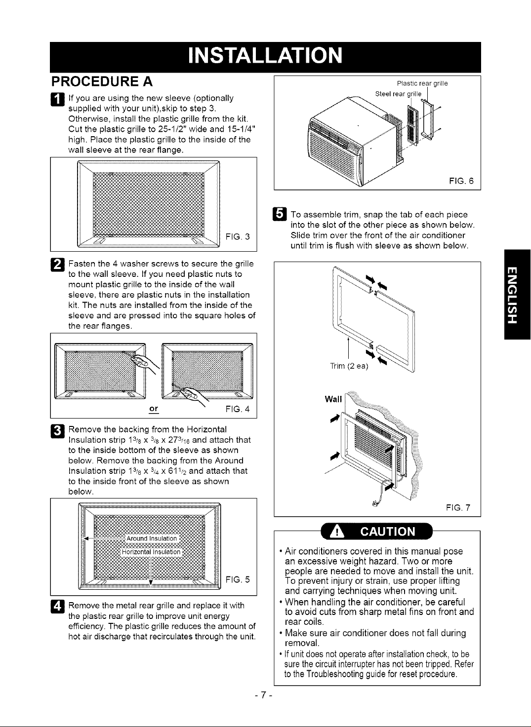
PROCEDURE A
you
O If are using the new sleeve (optionally
supplied with your unit),skip to step 3.
Otherwise, install the plastic grille from the kit.
Cut the plastic grille to 25-1/2" wide and 15-1/4"
high. Place the plastic grille to the inside of the
wall sleeve at the rear flange.
FIG. 3
_"_ Fasten the 4 washer screws to secure the grille
to the wall sleeve. If you need plastic nuts to
mount plastic grille to the inside of the wall
sleeve, there are plastic nuts in the installation
kit. The nuts are installed from the inside of the
sleeve and are pressed into the square holes of
the rear flanges.
PIastic rear grille
Steel rear
FIG. 6
_JTo assemble trim, snap the tab of each piece
into the slot of the other piece as shown below.
Slide trim over the front of the air conditioner
until trim is flush with sleeve as shown below.
Trim (2 ea)
FIG. 4
_J Remove the backing from the Horizontal
Insulation strip 13/8x 3/8x 273/16 and attach that
to the inside bottom of the sleeve as shown
below. Remove the backing from the Around
Insulation strip 13/8X 3/4X 611/2 and attach that
to the inside front of the sleeve as shown
below.
FIG. 5
D Remove the metal rear grille and replace it with
the plastic rear grille to improve unit energy
efficiency. The plastic grille reduces the amount of
hot air discharge that recirculates through the unit.
Wall
FIG. 7
•Air conditioners covered in this manual pose
an excessive weight hazard. Two or more
people are needed to move and install the unit.
To prevent injury orstrain, use proper lifting
and carrying techniques when moving unit.
•When handling the air conditioner, be careful
to avoid cuts from sharp metal fins on front and
rear coils.
• Make sure air conditioner does not fall during
removal.
, Ifunitdoesnotoperateafterinstallationcheck,to be
surethecircuitinterrupterhasnotbeentripped.Refer
totheTroubleshootingguidefor resetprocedure.
-7-
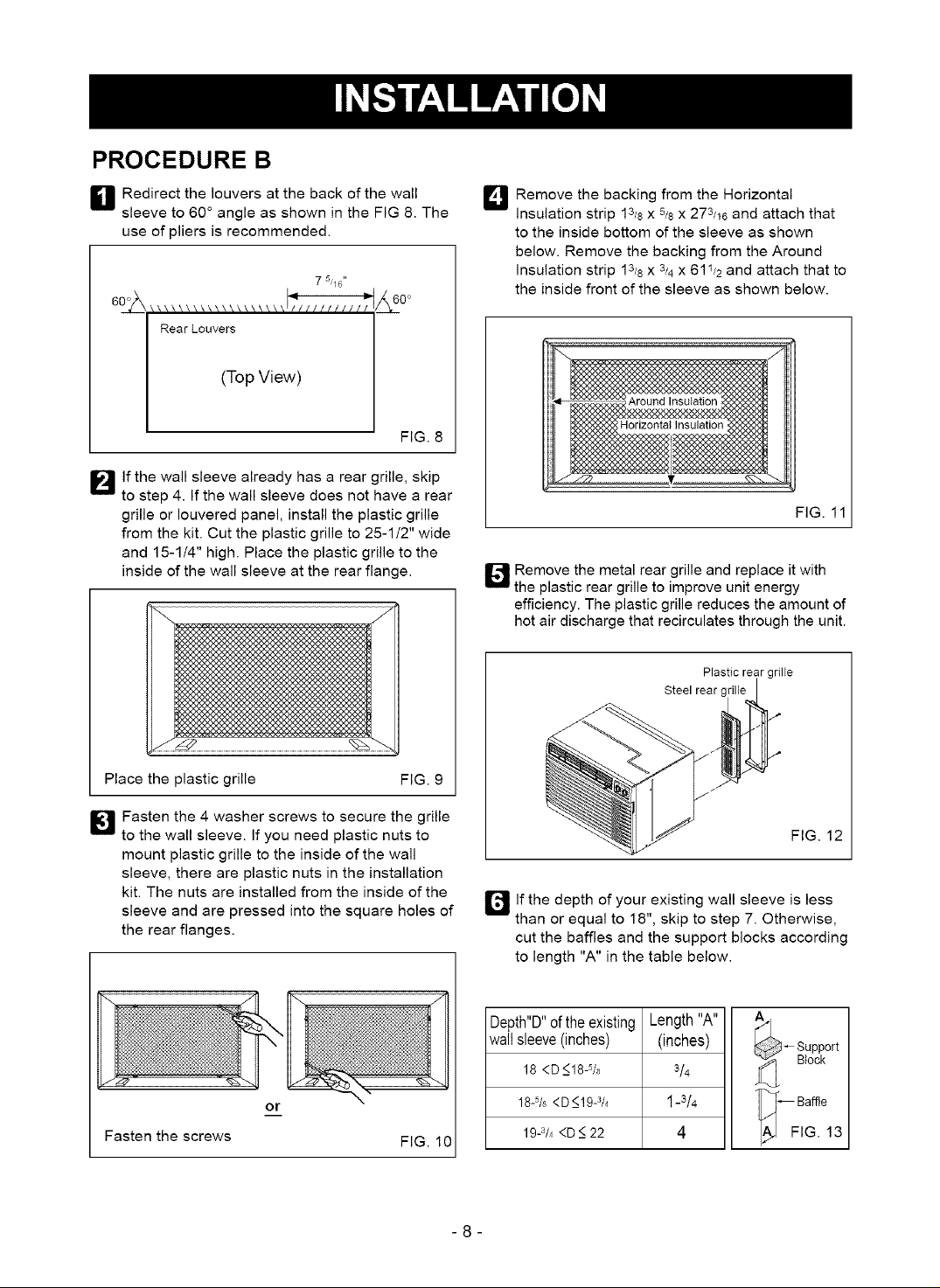
PROCEDURE B
H Redirect the louvers at the back of the wall
sleeve to 60 ° angle as shown in the FIG 8. The
use of pliers is recommended.
7 51/6"
Rear Louvers
(Top View)
FIG. 8
I_lf the wall sleeve already has a rear grille, skip
to step 4. If the wall sleeve does not have a rear
grille or Iouvered panel, install the plastic grille
from the kit. Cut the plastic grille to 25-1/2" wide
and 15-1/4" high. Place the plastic grille to the
inside of the wall sleeve at the rear flange.
_J Remove the backing from the Horizontal
Insulation strip 13/8x 5/8 x 273/16 and attach that
to the inside bottom of the sleeve as shown
below. Remove the backing from the Around
insulation strip 13/8 x 3/4 x 61 I/2 and attach that to
the inside front of the sleeve as shown below.
FIG. 11
1_4J Remove the metal rear grille and replace it with
the plastic rear grille to improve unit energy
efficiency. The plastic grille reduces the amount of
hot air discharge that recirculates through the unit.
Plastic rear grille
Steel rear grille
Place the plastic grille
I[_ Fasten the 4 washer screws to secure the grille
to the wall sleeve. If you need plastic nuts to
mount plastic grille to the inside of the wall
sleeve, there are plastic nuts in the installation
kit. The nuts are installed from the inside of the
sleeve and are pressed into the square holes of
the rear flanges.
or
Fasten the screws
FIG. 9
FIG. 10
ir_lf the depth of your existing wall sleeve is less
than or equal to 18", skip to step 7. Otherwise,
cut the baffles and the support blocks according
to length "A" in the table below.
Depth"D"oftheexisting
wallsleeve(inches)
18 <D _<18-5/8
18-5/8<D_<19-3/4
19-3/4<D _<22
Length"A"
(inches)
3/4
1-3/4
4
-8-
FIG. 12
_ upport
Block
• ._[_ Baffle
_J FIG. 13
PROCEDURE B
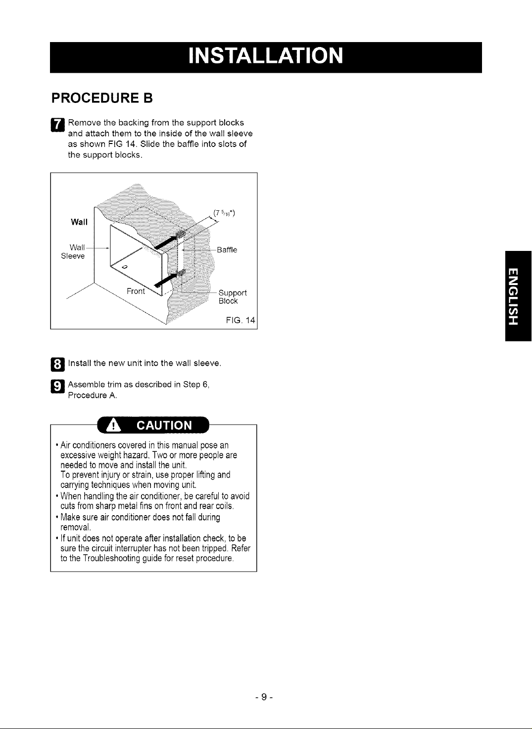
W Remove the backing from the support blocks
and attach them to the inside of the wall sleeve
as shown FIG 14. Slide the baffle into slots of
the support blocks.
Wall
Sleeve
Block
FIG. 14
D Install the new unit into the wall sleeve.
I_1 Assemble trim as described in Step 6,
Procedure A.
. Airconditionerscoveredinthis manualposean
excessiveweighthazard.Twoor morepeopleare
neededto moveandinstalltheunit.
Topreventinjuryor strain,useproperliftingand
carryingtechniqueswhenmovingunit.
. Whenhandlingtheairconditioner,becarefultoavoid
cutsfromsharpmetalfinsonfrontandrearcoils.
•Makesureairconditionerdoesnotfallduring
removal.
. Ifunitdoesnotoperateafterinstallationcheck,to be
surethecircuitinterrupterhas notbeentripped.Refer
totheTroubleshootingguideforresetprocedure.
-9-
PROCEDURE C
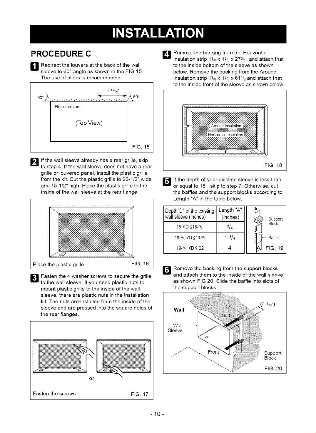
H Redirect the louvers at the back of the wall
sleeve to 60 ° angle as shown in the FIG 15.
The use of pliers is recommended.
7 13,/6 **
002 &to°
Rear Louvers
(Top View)
FIG. 15
_J Remove the backing from the Horizontal
insulation strip 13/8 x 13/8 x 273/16 and attach that
to the inside bottom of the sleeve as shown
below. Remove the backing from the Around
insulation strip 13/8 x 13/8 x 611/2 and attach that
to the inside front of the sleeve as shown below.
I_lf the wall sleeve already has a rear grille, skip
to step 4. If the wall sleeve does not have a rear
grille or Iouvered panel, install the plastic grille
from the kit. Cut the plastic grille to 26-1/2" wide
and 15-1t2" high. Place the plastic grille to the
inside of the wall sleeve at the rear flange.
Place the plastic grille
I[_ Fasten the 4 washer screws to secure the grille
to the wall sleeve. If you need plastic nuts to
mount plastic grille to the inside of the wall
sleeve, there are plastic nuts in the installation
kit. The nuts are installed from the inside of the
sleeve and are pressed into the square holes of
the rear flanges.
FIG. 16
FIG. 18
If the depth of your existing sleeve is less than
El
or equal to 18", skip to step 7. Otherwise, cut
the baffles and the support blocks according to
Length "A" in the table below.
Depth"D"of the existing
wailsleeve(inches)
18 <D_<18-%
18-5/8<D <19-3/4
19-3/4<D <_22
r_l Remove the backing from the support blocks
and attach them to the inside of the wall sleeve
as shown FIG 20. Slide the baffle into slots of
the support blocks
Length"A"
(inches)
3/4
1-3/4
4
_ upport
Block
k_ Baffle
FIG. 19
7 13'/6")
Wall
Sleeve
or
Fasten the screws FIG. 17
Block
"_. FIG. 20
-10-
PROCEDURE C
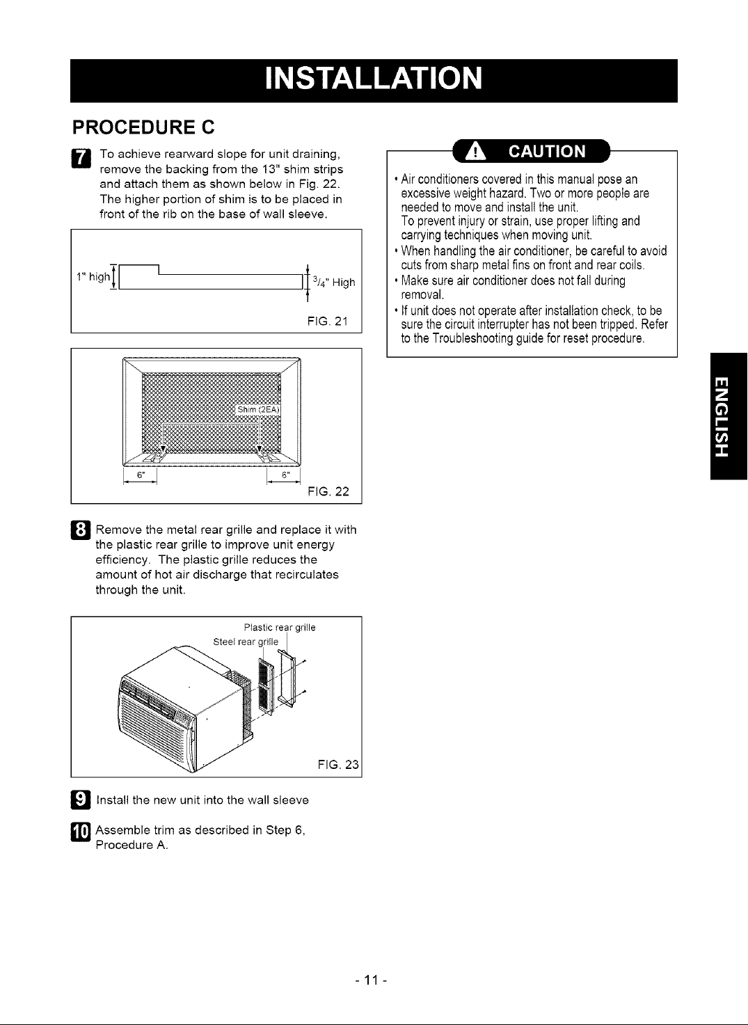
To achieve rearward slope for unit draining,
lil
remove the backing from the 13" shim strips
and attach them as shown below in Fig. 22.
The higher portion of shim is to be placed in
front of the rib on the base of wall sleeve.
h,0h_ r-
rear
_J_ Remove the metal and it with
the plastic rear grille to improve unit energy
efficiency. The plastic grille reduces the
amount of hot air discharge that recirculates
through the unit.
grille replace
l High
FIG. 21
FIG. 22
[H'.,_I]II[e] _1
• Airconditionerscoveredinthismanualposean
excessiveweighthazard.Twoor morepeopleare
neededto moveandinstallthe unit.
Topreventinjuryorstrain,useproperliftingand
carryingtechniqueswhen movingunit.
°Whenhandlingtheairconditioner,becarefultoavoid
cutsfromsharpmetalfinsonfrontandrearcoils.
, Makesureair conditionerdoesnotfallduring
removal.
• Ifunitdoesnotoperateafterinstallationcheck,tobe
surethe circuitinterrupterhasnotbeentripped.Refer
totheTroubleshootingguideforresetprocedure.
Plastic rear grille
Steel rear
_'_ Install the new unit into the wall sleeve
_1'_ Assemble trim as described in Step 6,
Procedure A.
FIG. 23
-11-
 Loading...