

Page 1

Owner's Manual
Manual del Propietario
KGnmore
©
ROOM AIR CONDITIONER ACONDICIONADOR DE AIRE DE VENTANA
Model, Modelo 580.72053
Sears, Roebuck and Co., Hoffman Estates, IL eOtlCSlU.SrA.
www.sears.com
Page 2

TABLE OF CONTENTS
TABLE OF CONTENTS..........................2
WARRANTY
SAFETY
Innportant Safety Instructions.......................3
ELECTRICAL REQUIREMENTS
INSTALLATION
Installation Requirements
Installation.....................................................6
How to Install
Removal from Window
OPERATION
How and Why................................................8
Normal Sounds
Capacity and Running Time
...........................................
...........................................................
................
.............................................
.............................
................................................
.................................
................................................
.............................................
.........................
Features
2
3
Using the Air Conditioner
Air Conditioner Features.............................10
.......................................................
.............................
9
9
MAINTENANCE...................................11
4
5
5
Air Filter Cleaning
Air Conditioner Cleaning
How to Remove the Front Grille
How to Replace the Front Grille
TROUBLESHOOTING
6
7
Before Calling for Service
......................................
............................
................
................
.........................
..........................
11
11
11
11
12
12
REPAIR PARTS ...................................14
8
ESPAÑOL
8
8
SERVICE NUMBERS
.....................................................
..................
Back Cover
24
WARRANTY
FULL ONE YEAR WARRANTY ON
ROOM AIR CONDITIONER
For one year from the date of purchase, when this
air conditioner is operated and maintained for
normal room cooling according to instructions in this
owner's manual, Sears will repair this air
conditioner, free of charge, if defective in material or
workmanship.
FULL FIVE-YEAR WARRANTY ON
SEALED REFRIGERATION SYSTEM
For five years from the date of purchase, when this
air conditioner is operated and maintained for
normal room cooling according to instructions in this
owner’s manual. Sears will repair the sealed
refrigeration system (consisting of refrigerant,
connecting tubing, and compressor), free of charge,
if defective in material or workmanship.
WARRANTY SERVICE IS AVAILABLE BY
CONTACTING THE NEAREST SEARS
SERVICE CENTER IN THE UNITED STATES.
Warranty coverage applies only to air conditioners
used for non-commercial, private household
purposes.
This warranty applies only while this product is in
use in the United States.
This warranty gives you specific legal rights, and
you may also have other rights which vary from
state to state.
Sears, Roebuck and Co., D/817WA,
Hoffman Estates, IL 60179 U.S.A.
2-
Page 3
SAFETY
IMPORTANT SAFETY INSTRUCTIONS
The safety instructions below will tell you how to use your room air conditioner to avoid harm to yourself or
damage to your ROOM AIR CONDITIONER.
AWARNiNG
Do not store or use gasoline or other flammable
vapors and liquids in the vicinity of this or any other
appliance. Read product labels for flammability and
other warnings.
Awarning
To reduce the risk of fire, electrical shock, or injury
to persons when using your air conditioner, follow
basic precautions, including the following;
• Be sure the electrical service is adequate for the
model you have chosen.
• If the air conditioner is to be installed in a window,
you will probably want to clean both sides of the
glass first. If the window is a triple-track type with a
screen panel included, you may want to remove
the screen completely before installation.
• Be sure the air conditioner has been securely and
correctly installed according to the separate
installation instructions provided with this manual.
Save this manual and installation instructions for
possible future use in removing or reinstalling this
unit. ’
• When handling the air conditioner, be careful to
avoid cuts from sharp metal fins on front and rear
coils.
Awarning
The complete electrical rating of your new room air
conditioner is stated on the serial plate. Refer to the
rating when checking the electrical requirements.
• Be sure the air conditioner is properly grounded.
To minimize shock and fire hazards, proper
grounding is important. The power cord is
equipped with a three-prong grounding plug for
protection against shock hazards.
• Your air conditioner must be plugged into a
properly grounded wall receptacle. If the wall
receptacle you intend to use is not adequately
grounded or protected by a time delay fuse or
circuit breaker, have a qualified electrician install
the proper receptacle.
■ Do not run air conditioner with outside protective
cover in place. This could result in mechanical
damage within the air conditioner.
• Do not use an extension cord or an adapter
plug.
FOR YOUR SAFETY
PREVENT ACCIDENTS
ELECTRICAL INFORMATION
Awarning
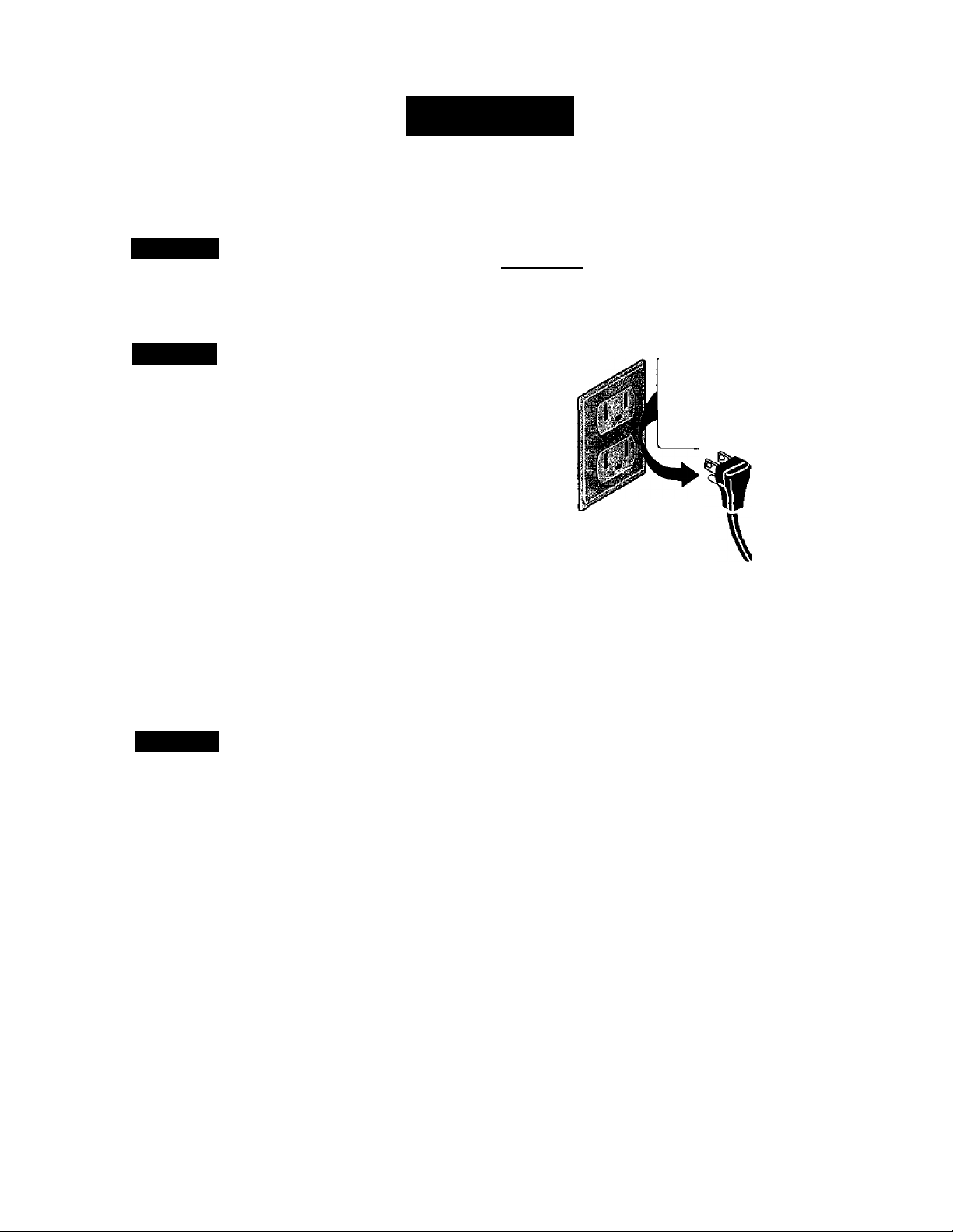
Do not use an extension cord or an adapter plug.
Do not remove any prong from the power cord.
Grounding type
wall receptacle
Avoid fire hazard or electric shock.
Do not under any
circumstances cut,
remove, or bypass
the grounding prong
from this plug.
Power supply cord
with 3-prong
grounding plug
ENERGY SAVING IDEAS
• The capacity of the room air conditioner must fit
the room size for efficient and satisfactory
operation.
• Install the room air conditioner on the shady side
of your home. A window that faces north is best
because it is shaded most of the day.
• Do not block air flow inside with blinds, curtains, or
furniture; or outside with shrubs, enclosures, or
other buildings.
• Close the floor and wall registers and the fireplace
damper so cool air does not escape up the
chimney and into the duct work.
• Keep blinds and drapes in other windows closed
during the sunniest part of the day.
■ Clean the air filter as recommended in the
MAINTENANCE section of this manual.
• Proper insulation and weather stripping in your
home will help keep warm air out and cool air in.
• External house shading with trees, plants or
awnings will help reduce the air conditioner’s work
load.
• Operate heat producing appliances such as
ranges, washers, dryers, and dishwashers during
the coolest part of the day.
Page 4
ELECTRICAL REQUIREMENTS
OBSERVE ALL LOCAL CODES AND ORDINANCES.
DO NOT, UNDER ANY CIRCUMSTANCES,
REMOVE THE POWER SUPPLY CORD
GROUND PRONG.
ELECTRICAL GROUND IS REQUIRED ON THIS APPLIANCE.
A 115-voit 60 Hz, AC only, 15A fused and
properly grounded electrical supply is required.
A time delay fuse or time delay circuit breaker
is recommended. Use a dedicated circuit,
serving only this appliance.
DO NOT USE AN EXTENSION CORD.
RECOMMENDED GROUNDING METHOD
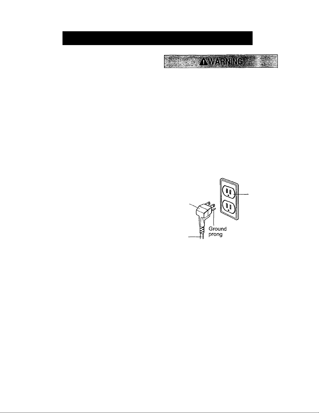
For your personal safety, this appliance must
be grounded. This appliance has a power
supply cord with a 3-prong grounding plug. To
minimize possible shock hazard, the cord must
be plugged into a mating grounding type wall
receptacle and grounded in accordance with
the National Electrical Code (ANSI/NFPA 70)
latest edition and all local codes and
ordinances. If a mating wall receptacle is not
available, it is the personal responsibility and
obligation of the customer to have a properly
grounded 3-prong wall receptacle installed by a
qualified electrician.
Electrical Shock Hazard
Plug into a grounded 3 prong outlet.
Do not remove ground prong.
Do not use an adapter.
Do not use an extension cord.
Failure to follow these instructions can result
in death, fire, or electrical shock.
3-prong
3-prong
grounding
plug
Power
supply
cord
grounding
type wall
receptacle
-4-
Page 5
INSTALLATION
INSTALLATION REQUIREMENTS installation hardware
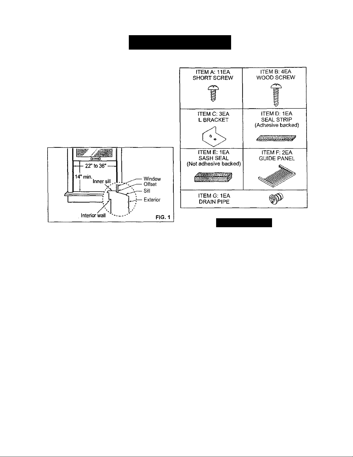
Your air conditioner will install into standard double
hung windows with actual clear opening widths of
22 to 36 inches (558mm to 914mm) (FIG. 1),
Lower sash must open sufficiently to allow a clear
vertical opening of 14 inches (356mm). Side louvers
and the rear of the air conditioner must have clear
air space to allow enough airflow through the
condenser for heat removal. The rear of the unit
must be outdoors, not inside a building or garage.
ELECTRICAL SERVICE
Check your available electrical service. The power
supply available must be the same as that shown
on the unit nameplate (found on left side of cabinet).
All models are equipped with a 3-prong service plug
to provide proper service and safe positive
grounding. Do not change plug in any way. Do not
use an adapter plug. If your present wall outlet does
not match your plug, call a qualified electrician to
make the necessary corrections. SAVE CARTON
and this OWNER'S MANUAL for future reference.
The carton is the best way to store unit during
winter or when not in use.
A CAUTION
To avoid risk of personal injury, property damage,
or product damage due to the weight of this
device and sharp edges that may be exposed;
• Air conditioners covered in this manual pose an
excessive weight hazard. Two or more people
are needed to move and install the unit.
To prevent injury or strain, use proper lifting and
carrying techniques when moving unit.
• Carefully inspect location where air conditioner
will be installed. Be sure it will support the weight
of the unit over an extended period of time,
• Handle air conditioner with care. Wear
protective gloves whenever lifting or carrying the
unit. AVOID the sharp metal fins of front and
rear coils.
• Make sure air conditioner does not fall during
installation.
REQUIRED TOOLS:
• Tight Fitting gloves
• Standard screwdriver
• Phillips screwdriver
• Pliers
■ Sharp knife
• Carpenters level
• 3/8-inch open end
wrench or adjustable
wrench
• 1 /4-inch hex socket
and ratcher
• Tape measure
• Electric drill
• 1/4-inch drill bit
-5-
Page 6
INSTALLATION
INSTALLATION
Pick a location which will allow you to blow the cold
air into the area you want. Windows used for
installation must be strong enough to support the
weight of the air conditioner. Good installation with
special attention to the proper position of the unit
will lessen the chance that service will be needed.
HOW TO INSTALL
GUIDE PANELS
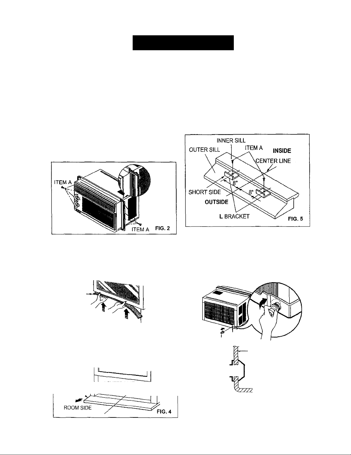
Insert the guide panels into the guides of the air
conditioner. Fasten the curtains to the unit with
screws (ITEM A), as shown in FIG. 2.
ATTACH L BRACKET
Install the L brackets on the outer sill with the short
side of the bracket against the back of the inner
sill. Install one L bracket 8" to each side of center
line. See FIG. 5.
The bracket helps to hold unit securely in place.
Be sure to place bracket edge flush against back
of inner sill. See FIG. 5.
If air conditioner is blockde by storm window
frame, see step 9.
SEAL STRIP
Cut the adhesive-backed seal strip (ITEM D) to the
window width.
Remove the backing from the seal strip and attach the
seal strip to the underside of the bottom window. (FIG. 3)
SEAL STRIP
(ITEM D)
F1G.3
LOCATING UNIT IN WINDOW
Open the window and mark center line with pencil
on the center of the inner sill, as shown in FIG. 4.
INNER SILL
CENTER LINE
DRAINAGE
First, be sure to insert the drain pipe into base pan
before installation.
The air conditioner must be installed with a slight tilt
downward for proper water drainage. The air
conditioner will drain the excess condensed water
through the drain pipe.
DRAIN CAP
DRAIN PIPE
BASE PAN REAR
DRAIN PIPE
N-
BASE PAN BOTTOM
FIG. 6
Page 7
INSTALLATION
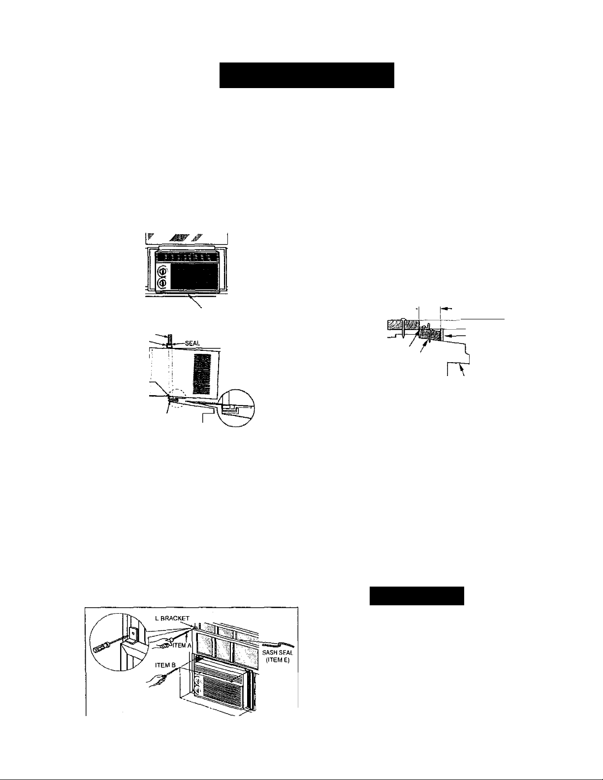
a INSTALL THE AIR CONDITIONER IN THE
WINDOW
Carefully lift the air conditioner and slide it into the
open window. Make sure the bottom guide of the air
conditioner drops into the notches of the L brackets.
When the air conditioner drops into the L brackets,
the air conditioner wilt be centered in window opening
as shown in FIG. 7.
While steadying the air conditioner, carefully bring the
window sash down behind the upper guide of the air
conditioner, as shown in FIG. 8.
LINE fig. 7
ABOUT 1/4"
FIG. 8
WINDOW frame
UPPER GUIDE
BOTTOM -
GUIDE
CENTER
L BRACKET
IF AIR CONDITIONER IS BLOCKED BY
STORM WINDOW FRAME
' If storm window presents interference, fasten a 2"
wide wood strip to the inner window sili across the full
width of the sill. The wood strip should be thick
enough to raise the height of the window sill so that
the unit can be installed without interference from the
the storm window frame. See FIG. 10,
Top of wood strip should be approximately 3/4"
higher than the storm window frame to help
condensation to drain properly to the outside.
• Install a second wood strip (approximately 6" long by
1V2" wide and same thickness as first strip) in the
center of the outer sill flush against the back of the
inner sill. Screw the L brackets into this strip.
This will raise the L bracket as shown in FIG. 10.
WOOD STRIP MOUNTED
ON TOP OF INNER SILL
INNER
SILL
INSIDE
L bracket;
h
1"MAX.
WOOD STRIP
FOR L BRACKET
3/4" 1
CLEARANCE t
STORM
WINDOW
FRAME
OUTER
SILL
OUTSIDE
FIG. 10
SECURE THE GUIDE PANELS
Extend the guide panels {ITEM F) to fill the
window opening using 4 screws (ITEM B) to
secure them, as shown in FIG. 9,
INSTALL THE SASH SEAL AND SASH LOCK
Cut the sash seal (ITEM E) to the window width.
Stuff the sash seal between the glass and the
window to prevent air and insects from getting into
the room, as shown in FIG. 9.
Fasten the remaining L bracket on either side of
the window using screw (ITEM A). See FIG. 9
inset. Installing this bracket prevents window from
being raised which may result in unit falling.
FIG. 9
REMOVAL FROM WINDOW
Turn the air conditioner off, and disconnect the
power cord. Remove the L bracket and the screws
installed through the top and bottom of the guide
panels, and save for reinstallation later. Close the
guide panels. Keeping a firm grip on the air
conditioner, raise the sash, and carefully tilt the air
conditioner backward, draining any condensate
water. Lift the air conditioner from the window and
remove the sash seal from between the windows.
A CAUTION
■ Air conditioners covered in this manual pose
an excessive weight hazard. Two or more
people are needed to move and install the unit.
To prevent injury or strain, use proper lifting
and carrying techniques when moving unit,
■ When handling the air conditioner, be careful
to avoid cuts from sharp metal fins on front and
rear coils.
• Make sure air conditioner does not fall during
removal.
-7-
Page 8
OPERATION
HOW AND WHY
Your room air conditioner provides №ie following
functions to make hot weather living more
comfortable:
• Cools and circulates room air.
• Lowers humidity by removing excess moisture.
• Filters out summertime dust, dirt, and some
airborne impurities.
The air conditioner performs these functions by
drawing room air through a filter which traps dost
and dirt particles. The air then passes over a
cooling coil which refrigerates the air and removes
excess moisture. The same air is then returned to
the room- cooler, drier, and cleaner. Moisture
removed from the room air is earned to the outside
and evaporated.
Your air conditioner is designed to be easy to
operate and to provide plenty of cooling power.
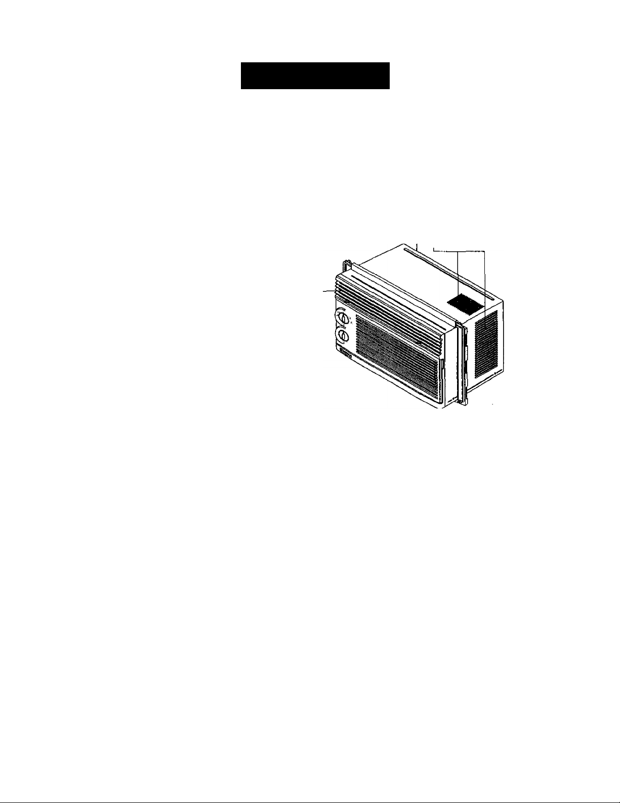
NORMAL SOUNDS fig.h
Aside from the regular fan motor and compressor
sounds coming from your air conditioner, you will
once in a while hear a pinging sound. This is the
result of moisture being picked up from Jhe air in the
room and thrown against the air conditioner's fan.
This is normal and should not be cause for concern.
Also, do not be alarmed if you hear a slight hissing or
gurgling sound coming from your air conditioner after
it is off. These are normal coolant noises.
-Compressor
The modern high efficiency
compressor may have a high
pitched hum or pulsating
noise that cycles on and off.
-Fan
You may hear air
movement from the
fan.
Unit Vibration
The unit may vibrate
and make noise
because of poor wall
or window
construction.
Condenser -
You may hear
droplets of water
hitting the condenser,
causing a pinging or
clicking sound.
CAPACITY AND RUNNING TIME
Proper unit size is important in deciding the desired
comfort for the area you want to cool. The proper
size is determined by the number of square feet in
the area to be cooled.
Whenever the heat or humidity load is above normal
the air conditioner must run longer and more often
to keep the desired temperature you have selected.
Under heavy heat load conditions the air conditioner
may need to run constantly to keep the temperature
you want.
At times using the HIGH FAN setting to circulate the
room air may make it comfortable even though you
do not have the air conditioner set to cool the air.
This will decrease your cost of use.
FIG. 11
-8
Page 9
OPERATION
FEATURES
USING THE AIR CONDITIONER
Awarmng
shock, or injury to persons, read the important
SAFETY instructions section before operating this
appliance.
To begin operating the air conditioner after
installation, follow these steps:
1. Plug in the air conditioner. {To prevent electrical
hazards, do not use an extension cord or an
adapter plug.)
2. Set the TEMP control to the coolest setting.
3. Set the MODE control at the highest COOL level.
4. Adjust the louvers for comfortable air flow.
5. Once the room has cooled, adjust the TEMP and
MODE control to the setting you find most
comfortable.
NOTE : If the air conditioner is turned off, wait 3
minutes before restarting. This allows pressure
inside the compressor to equalize. Failure to wait 3
minutes before restarting may cause inefficient
operation.
If you move the TEMP control to a warmer, then
immediately back to a cooler setting, the unit will
shut off.
Wait 3 minutes before restarting.
I To reduce the risk of fire, eiectric
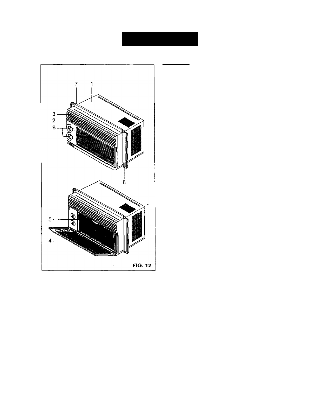
1. Cabinet
2. Horizontal Air Direction Control Tab
3. Cool Air Discharge
4. Inlet Grille
5. Air Filter
6. Control Knobs
7. Upper Guide
8. Curtain
Refer to the AIR CONDITIONER FEATURES
section for other settings.(See page 10)
-9-
Page 10
OPERATION
AIR CONDITIONER FEATURES AIR DIRECTION ADJUSTMENT
The controls featured in this manual are
representative of the many models available. Your
model may look slightly different.
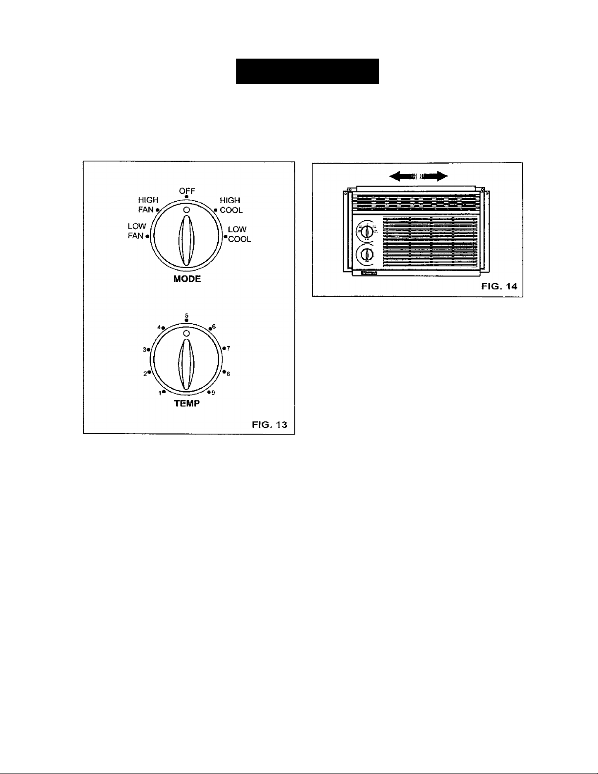
Using the Control Tabs, the air flow can be directed
to the left, right, straight ahead, or any combination
of these directions.
TEMP
The thermostat will automatically control the
temperature of the room. Select a higher number for
lower room temperature. The temperature is
selected by turning the TEMP knob to the desired
position.
The 5 or 6 position is a normai setting for average
conditions.
MODE
OFF ;
HIGH FAN :
LOW FAN ;
HIGH COOL :
LOW COOL ;
Turns the air conditioner off.
High fan speed operation without
cooling.
Low fan speed operation without
cooling.
Cooiing with high fan speed
operation.
Cooling with low fan speed
operation.
- 10
Page 11
MAINTENANCE
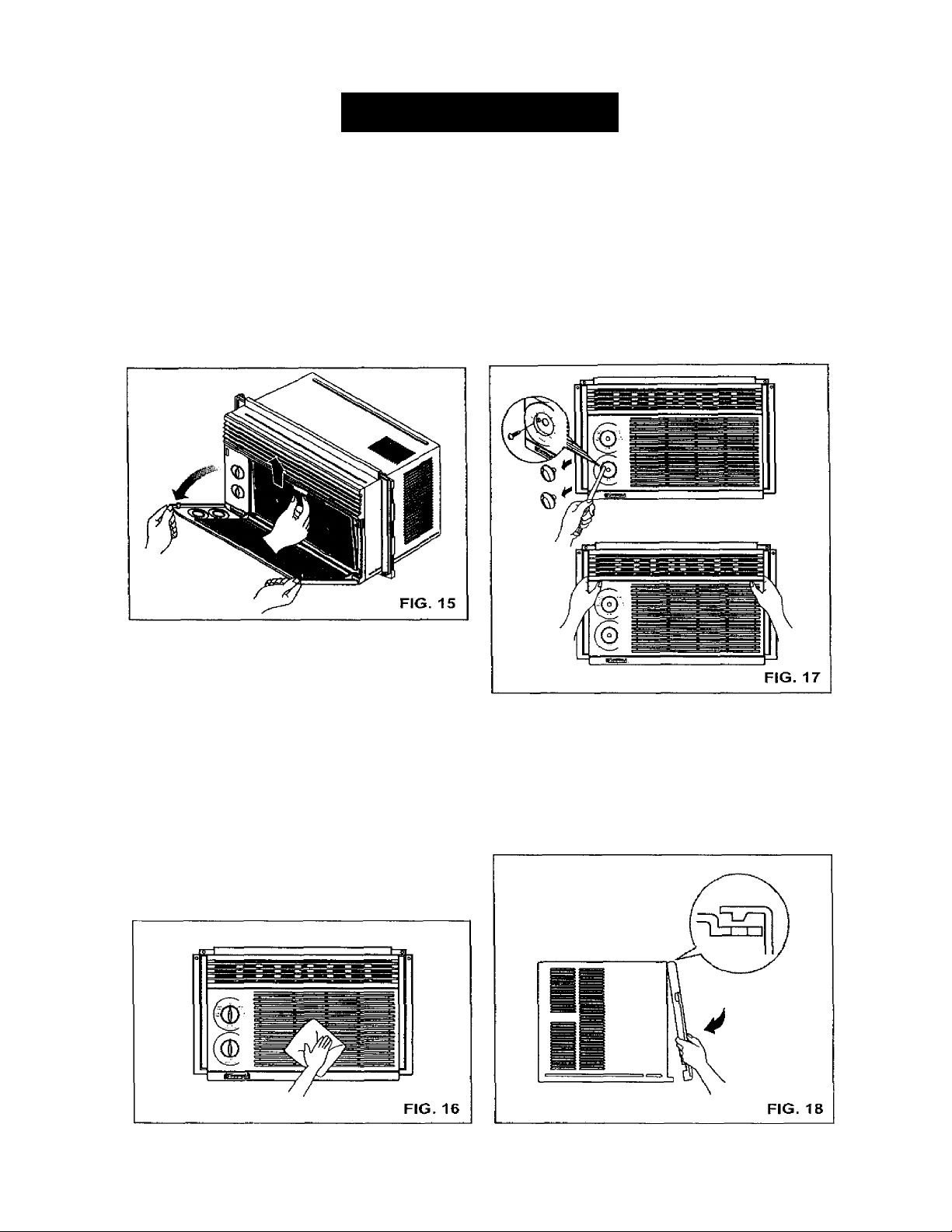
AIR FILTER CLEANING
The Air Filter will become dirty as it removes dust
from the inside air. It should be washed at least
every 2 weeks. If the Air Filter remains full of dust,
the air flow will decrease and the cooling capacity
will be reduced, possibly damaging the unit.
• Pull the inlet grille forward and pull out the air filter.
* Wash the Air Filter under the faucet with warm
water. Be sure to shake off all the water before
replacing the filter.
HOW TO REMOVE THE FRONT
GRILLE
• Remove the TEMP knob and the MODE knob by
pulling.
• Remove the screw securing the Front Grille.
• Push the grille up from the bottom and pull the top
of the grille away from the case to lift the top tabs
out of their slots.
AIR CONDITIONER CLEANING
Clean the front grille and inlet grille by wiping with a
cloth dampened in a mild detergent solution.
The cabinet may be washed with mild soap or
detergent and lukewarm water, then polished with
liquid appliance wax.
To ensure continued peak efficiency, the condenser
coils (outdoor side at unit) should be checked
periodically and cleaned if they become clogged
with soot or dirt from the atmosphere. Brush or
vacuum exterior coils to remove debris from fins.
HOW TO REPLACE THE FRONT GRILLE
Attach the front grille to the cabinet by inserting the
tabs on the grille into the tabs on the front of the
cabinet. Push the grille in until it snaps into place.
- 11 ^
Page 12
TROUBLESHOOTING
BEFORE CALLING FOR SERVICE
Check the following list to be sure a service call is really necessary. A quick reference to this manual may
help you avoid an unneeded service call.
THE AIR CONDITIONER WILL NOT OPERATE
Check if... Then...
Wall plug disconnected.
House fuse blown or circuit breaker tripped. Replace fuse with time delay type or reset circuit breaker.
MODE selector is OFF position.
Unit was turned off and then on too quickly.
TEMP Control set warmer than room temperature.
AIR FROM UNIT DOES NOT FEEL COLD ENOUGH. Check if... Then...
MODE selector in a LOW COOL positicwi. Turn selector to a HIGH COOL position
TEMP Control set too warm (lower number).
Room temperature below 70°F (21 °C). Cooling may not occur until room temperature rises above 70°F (21 °C).
Temperature sensing tube touching cold coil,
located behind air filter.
THE AIR CONDITIONER COOUNG, BUT ROOM IS TOO WARM - ICE FORNBNG ON COOUNG COIL BEHIND INLET GRILLE
Check if... Then...
Outdoor temperature below 70°F (21 °C). To defrost tile coil, set selector to FAN position. Then, turn TEMP control
Air filter may be dirty.
TEMP Contrcrf set too cold for night-time cooling.
Push plug finmiy into wall outlet.
Turn MODE selector to the cleared COOL setting.
Turn unit off and wait 3 minutes before restarting.
Turn ТЕМ P Control dockwise to a cooler setting (higher number).
Turn TEMP Control ciockwise to a cooler setting.
Straighten tube away from coil.
counterclockwise to a warmer setting.
Clean filter. Refer to Maintenance section of owner's manual. To defrost,
set selector to FAN poation.
To defrost the coil, set selector to a FAN position. Then, set the MODE
control at FAN position or "High CooT with the TEMP contrd to a warmer position.
THE AIR CONDITIONER COOUNG, BUT ROOM IS TOO WARM - NO ICE FORMING ON COOUNG COIL BEHIND INLH GRILLE.
Check if... Then...
Ditty air filter - air restricted.
TEMP Control set too warm.
Front of unit is blocked by drapes, blinds, fomiture,
etc. Air distribution is restricted.
Doors, windows, registers, etc. open. Cold air escapes.
Unit recently turned on in hot room.
Clean air filter. Refer to Maintenance section of owner’s manual.
Turn TEMP control dockwise to a cooler setting (higher number).
Clear blockage in front of unit.
Close doors, windows, registers, etc.
Allow additional time to remove stored heat from walls, ceiling, floor, and furniture.
THE AIR CONDITIONER TURNS ON AND OFF RAPIDLY. Check if... Then...
Outside temperature is extremely hot
Set MODE on HIGH speed to bring air past cooling coils faster.
NOISE WHEN UNIT IS COOLING.
Check if...
Sound of fen hitting water - moisture removal system.
Window vibration - poor installation.
Then...
This is nomnal when humidity is high. Close doors, windows, and registers.
Refer to installation instructions or check with installer.
WATER DRIPPING INSIDE WHEN UNIT IS COOLING.
Check if...
The air conditioner is improperly installed.
Then...
Tilt air conditioner slightly to the outside to allow water drainage. Refer to
installation instructions or check with installer.
WATER DRIPPING OUTSIDE WHEN UNIT IS COOLING.
Check if...
The unit is removing large quantities of moisture
from humid room.
Then...
This is normal during excessively humid days.
-12-
Page 13

ENGLISH
CO
Page 14
REPAIR PARTS
Room Air Conditioner To order Parts call Toll Free
Model No. 580.72053100 1-800-4-MY-HOME®(1-800-469-4663)
CAUTION: Use the Kenmore part number on all orders, not the illustration number.
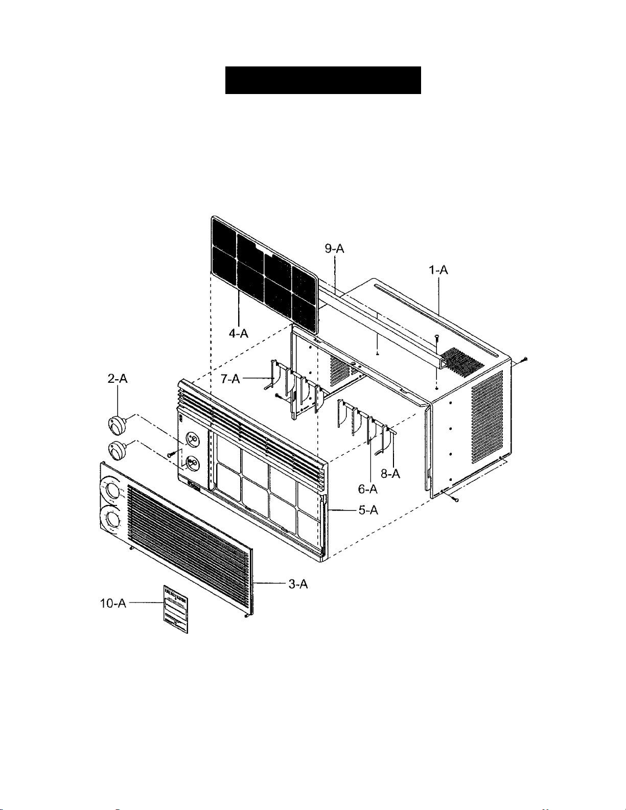
CABINET & FRONT GRILLE ASS'Y
11/00
-14-
Page 15

580.72053100
CAUTION: Use the Kenmore part number on all orders, not the illustration number.
CABINET & FRONT GRILLE ASST
POS. NO
1 - A
2-A
3-A 3530AR1343A GRILLE, INLET
4 - A
5-A 3530AR1344A
6-A 5900AR3190B
7-A 5900AR3190A
8-A 4520AR3191A
9-A 5210AR3196C
10-A
PART NO
3091A10020A
4941AR3813A
5231AR2148A
3850A20043T
3828A20049Y
DESCRIPTION
CABINET ASSY
KNOB ASSY
AIR FILTER ASSY
GRILLE. FRONT
VANE
VANE
LINK HOLDER
UPPER GUIDE
ENERGY GUIDE LABEL
OWNER’S MANUAL
m
Z
o
d
00
I
# = Functional Parts
* = Non-lllustrated Parts
^ 15-
11/00
Page 16
580.72053100
CAUTION: Use the Kenmore part number on all orders, not the illustration number.
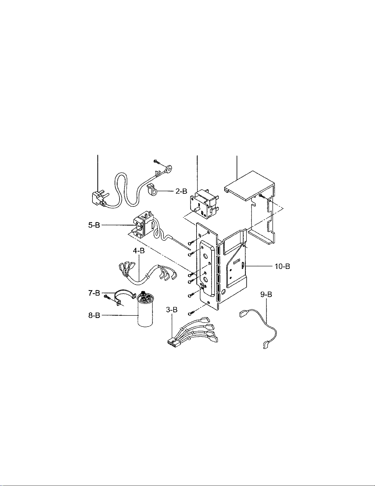
CONTROL BOX ASS'Y
1-B
6-B
11-B
11/00
-16-
Page 17

580.72053100
CAUTION: Use the Kenmore part number on all orders, not the illustration number.
CONTROL BOX ASS’Y
POS. NO
1 - B #
2-B
3-B
4- B
5- B #
6-B #
7 -B
8 -B #
9-B
10-B
11 -B
PART NO
2H00677P
4H01254A
6877A20001G LEAD WIRE ASSY
6631AR3843R
2H01109H
2H00154H
4H00442F
6120AR2359V
2H01045E
4994A20016A
3550A20026A
DESCRIPTION
POWER CORD ASSY
CLIP
CONDUCTOR ASSY
THERMOSTAT ASSY
SWITCH, ROTARY
CLAMP, CAPACITOR
CAPACITOR
CONDUCTOR ASSY
CONTROL BOX, SINGLE
COVER
# = Functional Parts
* = Non-lllustrated Parts
-17
11/00
Page 18
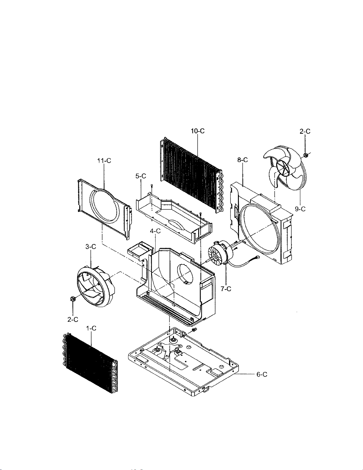
580.72053100
CAUTION: Use the Kenmore part number on all orders, not the illustration number.
AIR HANDLING & CYCLE PARTS
11/00
-18-
Page 19

580.72053100
CAUTION: Use the Kenmore part number on all orders, not the illustration number.
AIR HANDLING & CYCLE PARTS
POS. NO
1 -C # 5421A10008B
2-C
3-C # 5900A20005A FAN, TURBO
4-C
5-C 5238A20004A
6-C 3041A10011E
7 -C # 4681A10002A MOTOR ASSY, SINGLE
8-C 4998A10006A
9-C #
10-C #
11 -C 4948A10007A
PART NO
3H02932B
5239A30003A
5900A20006A FAN. PROPELLER
5403A20038D
DESCRIPTION
EVAPORATOR ASSY
CLAMP, SPRING
AIR GUIDE, LOWER
AIR GUIDE, UPPER
BASE ASSY. SINGLE
SHROUD
CONDENSER ASSY
ORIFICE
# = Functional Parts
* = Non-lllustrated Parts
- 19.
11/00
Page 20
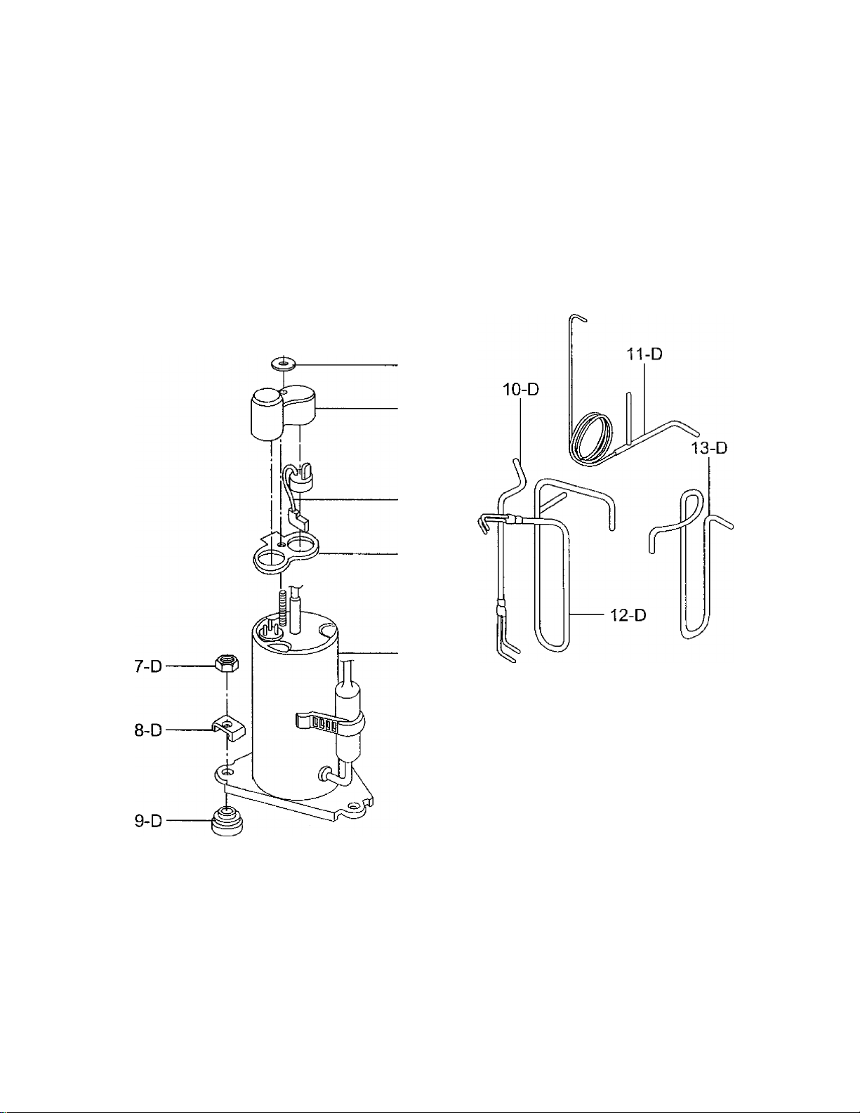
580.72053100
CAUTION: Use the Kenmore part number on all orders, not the illustration number.
COMPRESSOR PARTS
1- D
2- D
3- D
4- D
5- D
6-D
11/00
20
Page 21

580.72053100
CAUTION: Use the Kenmore part number on all orders, not the illustration number.
COMPRESSOR PARTS
POS. NO
1 - D
2- D
3-D
4-D #
5-D
6 - D #
7-D
8-D
9-D
10-D
11 -D
12-D
13 - D
PART NO
4H00947A
4H01058A GASKET NUT
3550U-L004A COVER
6750U-L050A
4986U-L001G GASKET
2520UABC2EA
1NHA0801206 HEXAGON NUTS
4810AR4155B
5040AR4195A
5211A10063A
5211A10065B
5211A10062A
5210A20252A
DESCRIPTION
NUT, TERMINAL COVER
OVER LOAD PROTECTOR
COMPRESSOR
BRACKET, WASHER
RUBBER, MOUNTING
TUBE ASS‘Y, EVAPORATOR
TUBE ASS'Y, CAPILLARY
TUBE ASS'Y, SUCTION
TUBE DISCHARGE
# = Functional Parts
* Non-lllustrated Parts
-21 -
11/00
Page 22
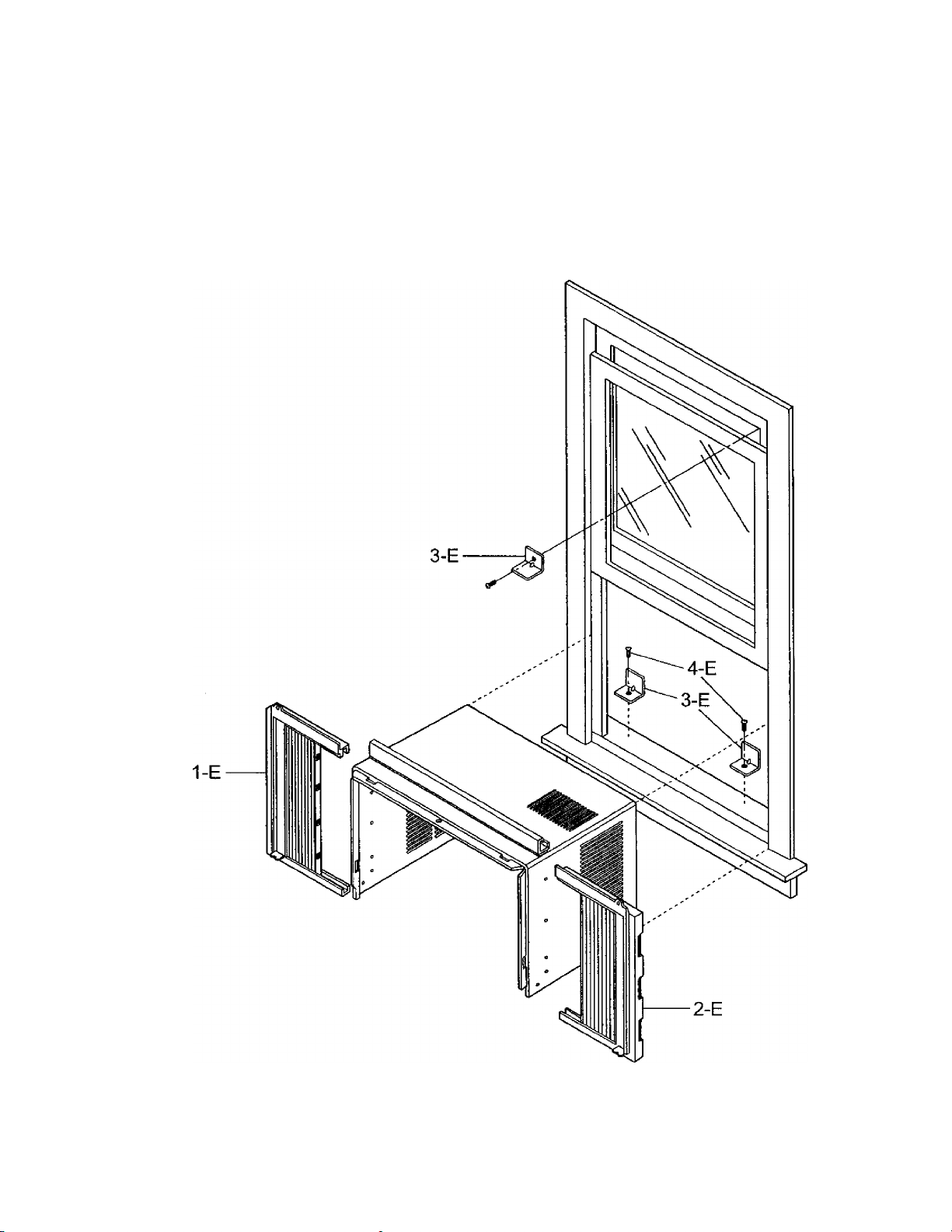
580.72053100
CAUTION: Use the Kenmore part number on all orders, not the illustration number.
INSTALLATION KIT ASS'Y
11/00
-22-
Page 23

580.72053100
CAUTION: Use the Kenmore part number on all orders, the illustration number.
INSTALLATION KIT ASS'Y
POS. NO
1 - E
2-E
3-E
4-E
PART NO
3211AR3239B
3211AR3239A
4810A30113A
1TTG0402618
DESCRIPTION
GUIDE PANEL, LEFT
GUIDE PANEL, RIGHT
L BRACKET
SHORT SCREW
# = Functional Parts
* = Non-lllustrated Parts
-23-
11/00
 Loading...