

Page 1
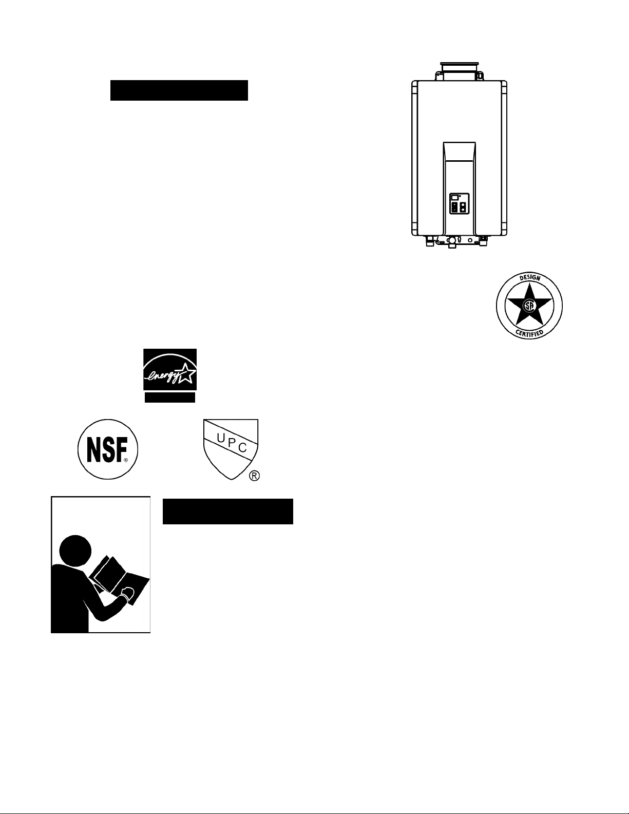
Owner’s Manual
Kenmore
305 and 505 Models
Direct Vent Tankless Water Heaters
FOR INDOOR APPLICATIONS ONLY
MODEL NO.
154.330020
154.330030
154.330060
154.330070
Natural Gas
Propane Gas
Natural Gas
Propane Gas
305 Series
305 Series
505 Series
505 Series
Safety Instructions
Installation
Operation
Care and Maintenance
Troubleshooting
ENERGY STAR
AWARNING
Read and understand instruction
manual and safety messages
before installing, operating or
servicing this water heater.
Failure to follow instructions and
safety messages could result in
death or serious injury.
Instruction manual must remain
with water heater.
INSTALLER:
• AFFIX THESE INSTRUCTIONS TO OR
ADJACENT TO THE WATER HEATER.
OWNER:
• RETAIN THESE INSTRUCTIONS AND
WARRANTY FOR FUTURE REFERENCE.
RETAIN THE ORIGINAL RECEIPT AS PROOF
OF PURCHASE.
For Your Safety
AN ODORANT IS ADDED TO THE GAS USED BY THIS WATER HEATER.
WARNING: If the information in these
instructions is not followed exactly, a fire
or explosion may result causing property
damage, personal injury or death.
— Do not store or use gasoline or other
flammable vapors and liquids in the
vicinity of this or any other appliance.
— WHAT TO DO IF YOU SMELL GAS:
• Do not try to light any appliance.
• Do not touch any electrical switch; do
not use any phone in your building.
• Immediately call your gas supplier
from a neighbor’s phone. Follow the
gas supplier’s instructions.
• If you cannot reach your gas supplier,
call the fire department.
— Installation and service must be
performed by a qualified installer,
service agency or the gas supplier.
PRINTED IN THE U.S.A 0409
Sears, Roebuck and Co., Hoffman Estates, IL 60179 U.S.A
www.sears.com
PART NO. 316051-001
Page 2
SAFE INSTALLATION, USE AND SERVICE
Your safety and the safety of others is extremely important in the installation, use and servicing of this water heater.
Many safety-related messages and instructions have been provided in this manual and on your own water heater to warn you and others of
a potential injury hazard. Read and obey all safety messages and instructions throughout this manual. It is very important that the meaning
of each safety message is understood by you and others who install, use or service this water heater.
This is the safety aiert symboi. it is used to aiert you to potentiai personai injury hazards.
A
Obey aii safety messages that foiiow this symboi to avoid possibie injury or death.
.DANGER
^WARNING
^CAUTION
CAUTION
Aii safety messages wiii generaiiy teii you about the type of hazard, what can happen if you do not foiiow the safety message and
how to avoid the risk of injury.
The California Safe Drinking Water and Toxic Enforcement Act requires the Governor of California to publish a list of substances known to
the State of California to cause cancer, birth defects, or other reproductive harm, and requires businesses to warn of potential exposure
to such substances. WARNING: This product contains a chemical known to the State of California to cause cancer, birth defects, or other
reproductive harm. This appliance can cause low-level exposure to some of the substances included in the Act.
• Qualified Technician: A qualified technician must have ability equivalent to a licensed tradesman in the fields of plumbing, air supply,
venting, and gas supply, including a thorough understanding of the requirements of the National Fuel Gas Code as it relates to the
installation of gas fired water heaters. The qualified technician must also have a thorough understanding of this instruction manual.
• Service Agency: A service agency also must have ability equivalent to a licensed tradesman in the fields of plumbing, air supply, venting
and gas supply, including a thorough understanding of the requirements of the National Fuel Gas Code as it relates to the installation of
gas fired water heaters. The service agency must also have a thorough understanding of this instruction manual, and be able to perform
repairs strictly in accordance with the service guidelines provided by the manufacturer.
• Gas Supplier: The natural gas or propane utility or service who supplies gas for utilization by the gas burning appliances within this
application. The gas supplier typically has responsibility for the inspection and code approval of gas piping up to and including the natural
gas meter or propane storage tank of a building. Many gas suppliers also offer service and inspection of appliances within the building.
DANGER indicates an imminentiy hazardous situation which, if not avoided, wiii
resuit in death or injury.
WARNiNG indicates a potentiaiiy hazardous situation which, if not avoided, couid resuit
in death or injury.
CAUTiON indicates a potentiaiiy hazardous situation which, if not avoided, couid resuit
in minor or moderate injury.
CAUTiON used without the safety aiert symboi indicates a potentiaiiy hazardous
situation which, if not avoided, couid resuit in property damage.
IMPORTANT DEFINITIONS
SAFETY PRECAUTIONS
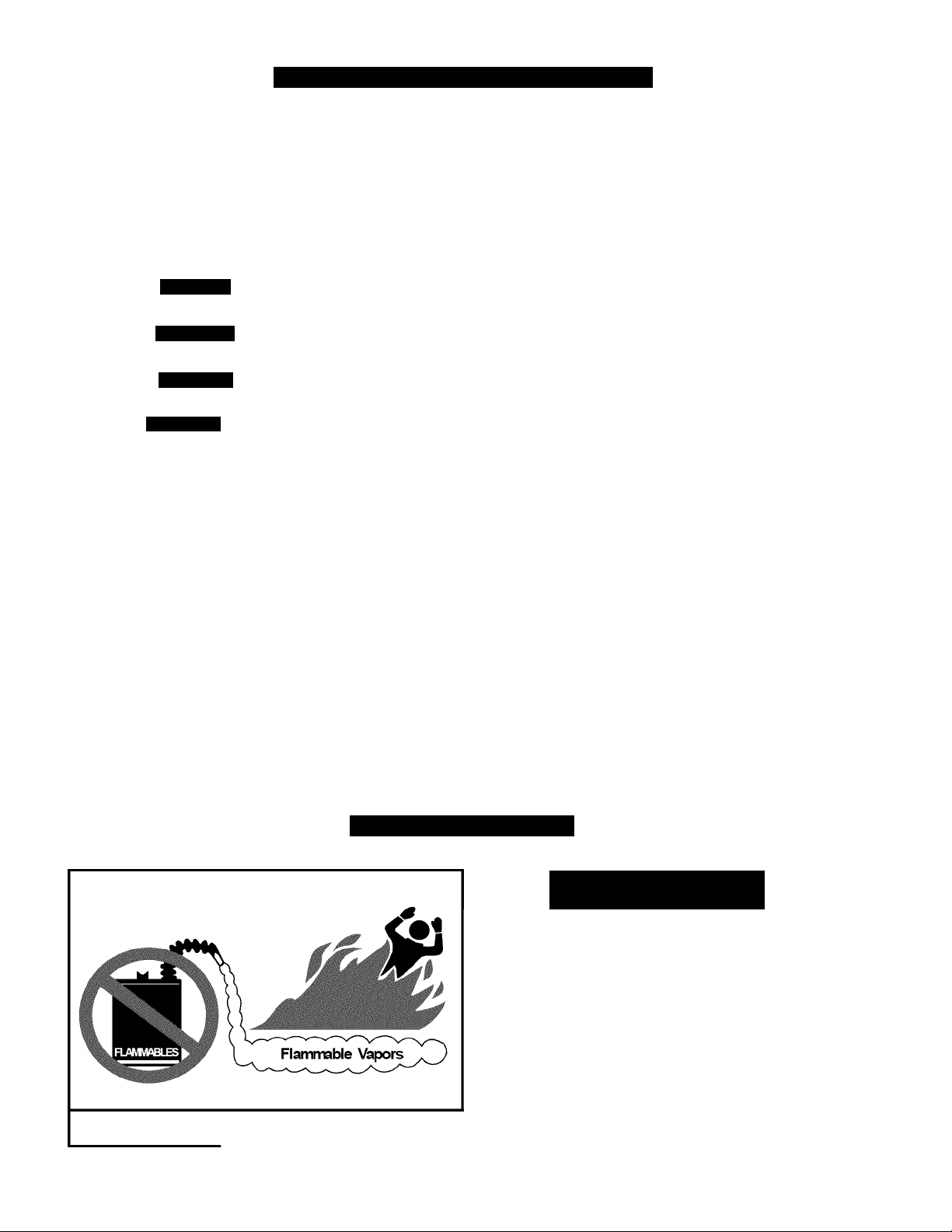
FIRE AND EXPLOSION HAZARD
A
flammable vapors and liquids in the vicinity of this
or any other appliance. Storage of or use of
gasoline or other flammable vapors or liquids in the
vicinity of this or any other appliance can result in
serious injury or death.
Read and follow water heater warnings and instructions.
© Sears, Roebuck and Co.
2 305 & 505 Indoor Manual
AWARNING
Can result in serious injury or death
Do not store or use gasoline or other
Page 3

Safety Behavior and Practices
A WARNING
Keep the area around the appliance clear and free
from combustible materials, gasoline, and other
flammable vapors and liquids.
Do not use this appliance if any part has been
underwater. Immediately call a qualified service
technician to inspect the appliance and to replace
any part of the control system and any gas control
which has been under water.
Safety Features
Overheat: The appliance will automatically shut
down when the appliance exceeds a predetermined
temperature.
Flame Failure: The appliance will automatically
shut down if the burner flame is extinguished.
Power Failure: The appliance will cut off the gas if
it loses electrical power.
This appliance is equipped with a three-prong
plug for your protection against shock hazard and
should be plugged directly into a properly grounded
three prong receptacle. Do not cut or remove the
ground prong from this plug.
Any alteration to the appliance or its controls can
be dangerous and will void the warranty.
Always check the water temperature before
entering a shower or bath.
Power Surge Fuse: A glass fuse protects against
overcurrent. If the fuse blows then all indicator
lamps will be off.
Fusible Link: In case the overheat feature does not
prevent the temperature from rising then the fusible
link will break shutting off the appliance.
305 & 505 Indoor Manual
Page 4

TABLE OF CONTENTS
Safe Installation, Use and Service..................................2
Safety Precautions..........................................................2
Safety Behaviors and Practices
Safety Features........................................................3
Table of Contents............................................................4
Product Warranty
Consumer Responsibilities
Product Specifications
Dimensions
Technical Data
Pressure Drop Curve
Outlet Flow Data.......................................................9
Installation Instructions
General Instructions
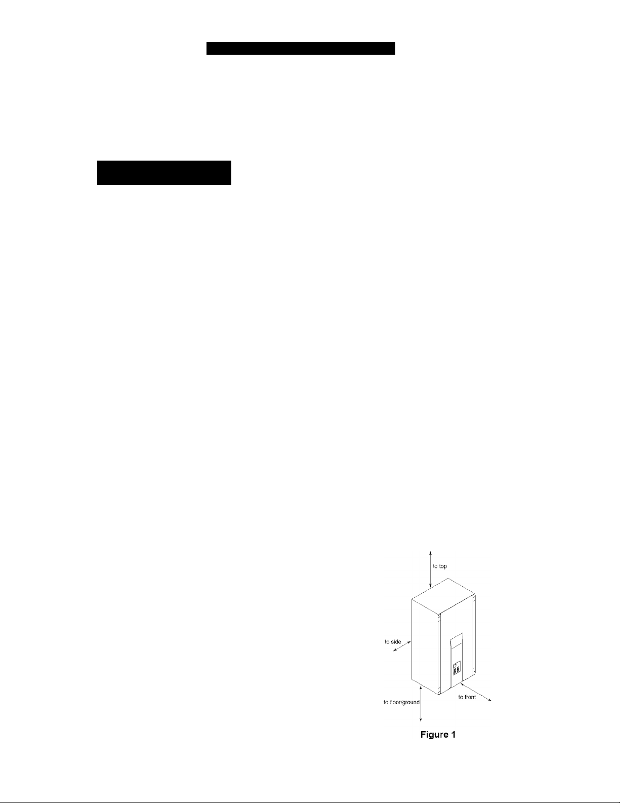
Clearances from Appliance.....................................10
Attachment of the Water Heater
Electrical Connection.............................................11
Gas Supply
General Instructions
Pipe Sizing Procedure - Example
Water Piping..................................................................13
General Instructions
Pressure Relief Valve
Freeze Protection
Recommended Piping For Basic Installation
Recommended Piping For
Circulation Systems
Optional Piping For Circulation Systems
Vent Instructions............................................................18
Intake / Exhaust Guidelines
Condensate............................................................18
Maximum Vent Length
Vent Products................................................................19
Listed and Tested Vent Products for the 305 and
505 Models.............................................................19
Flue Terminal Clearances
(ANS Z21.10.3 • CSA4.3)
Additional Clearances - Vent Terminal
Flue Installation For 305 And 505 Models
............................................................
.............................................
....................................................
.....................................................................
................................................................
...............................................
.................................................
...............................................
...................................................................
..............................................
...............................................
............................................
.............................................
...............................................
...........................................
...............................
............................
.........................
13-14
..........
...............
...................................
......................................
..................
............
10
10
11
11
11
12
13
13
15
16
17
18
18
19
20
21
High Altitude Installations
Connecting Multiple Water Heaters
3
5
6
7
8
9
9
Temperature Controller Installation
Location..................................................................23
Configurations
Cable Lengths And Size
Mounting The Controller
Description of Operation
Operating Instructions...................................................24
Sequence of Operation
Features Available on Temperature Controllers..24
Temperature Adjustment...............................................25
Temperature Ranges..............................................26
Setting the Controller to Mute.................................26
Operating Your Water Heater
Maintenance..................................................................28
Cleaning..................................................................28
Vent System
Motors.....................................................................28
Temperature Controller
Lime/Scale Build-up
Snow Accumulation................................................28
Visual Inspection of Flame
Troubleshooting.......................................................29-31
Error Code Table...............................................29-30
Troubleshooting for Common Issues.....................31
Accessing Operating Information...........................31
Water Quality..........................................................31
Flushing the Heat Exchanger
(Error Code: LC or 00)............................................32
Wiring Diagram..............................................................33
Service and Adjustment
Repair Parts List.....................................................34
Kenmore Tankless Water Heater Accessories.... 34
Notes.............................................................................35
...........................................................
.............................................
..............................
..............................
........................................................
........................................
........................................
...............................................
..........................................
.......................................
..........................................
...............................................
.....................................
................................................
22
22
23
23
23
23
24
24
27
28
28
28
28
34
305 & 505 Indoor Manual
Page 5

PRODUCT WARRANTY
12 Year Limited Warranty on Heat Exchanger
For 12 years from the date of purchase, if this water heater is installed and operated in a single family home in
accordance with the owner’s manual instructions and all local codes. Sears will supply a free heat exchanger for one
that develops a leak.
For the second through tW'clfth year from purchase date, you must pay the labor cost for installation of the heat
exchanger
5 Year Limited Warranty on Parts
For 5 years from the date of purchase, if this water heater is installed and operated in a single family home in
accordance with the owner’s manual instructions and all local codes, if a part fails due to material or workmanship.
Sears will supply a free replacement part.
1 Year Exclusive Kenmore Labor Warranty
For the first year from the date of purchase. Sears will, free of charge, supply and install new water heater parts for
defective ones or a new heat exchanger for one that develops a leak.
Warranty Service
To obtain warranty seiv’ice, call l-800-4-MY-HOME(iD (1-800-469-4663). This warranty applies only while this
product is in the United States.
For Commercial, institutional, industrial, or residential use by two or more families, the above limited warranty for
heat exchanger leaks is effective for five years from date of purchase and the above parts warranty is effective for
three years from the date of purchase.
This warranty gives you specific legal rights and you may also have other rights which vary from state to state.
SEARS, ROEBUCK AND CO., Dept.817WA, Hoffman Estates, IL 60179
The price of your water heater does not include a free checkup service call. On water heater installations arranged by Sears, Sears
warrants the installation.
A charge will be made on service calls due to poor or incomplete installation. These include:
a. Adjusting thermostat b. Condensation c. Leaks in pipes or fittings
Master Protection Agreements
Congratulations on making a smart purchase. Your new
Kenmore® product is designed and manufactured for years
of dependable operation. But like all products, it may require
preventive maintenance or repair from time to time. That’s when
having a Master Protection Agreement can save you money and
aggravation.
The Master Protection Agreement also helps extend the life of your
new product. Here’s what the Agreement* includes:
• Parts and labor needed to help keep products operating
properly under normal use, not just defects. Our coverage
goes well beyond the product warranty. No deductibles, no
functional failure excluded from coverage— real protection.
• Expert service by a force of more than 10,000 authorized
Sears service technicians, which means someone you can
trust will be working on your product.
• Unlimited service calls and nationwide service, as often as
you want us, whenever you want us.
• “No-lemon” guarantee - replacement of your covered product
if four or more product failures occur within twelve months.
• $250 Food Loss Protection annually for any food spoilage
that is the result of mechanical failure of any covered
refrigerator or freezer.
• Rental reimbursement if repair of your covered product takes
longer than promised.
• 10% discount off the regular price of any non-covered repair
service and related installed parts.
Once you purchase the Agreement, a simple phone call is all that it
takes for you to schedule service. You can call anytime day or night,
or schedule a service appointment online.
The Master Protection Agreement is a risk free purchase. If you
cancel for any reason during the product warranty period, we
will provide a full refund. Or, a prorated refund anytime after the
product warranty period expires. Purchase your Master Protection
Agreement today!
Some limitations and exclusions apply. For prices and additional
information in the U.S.A. call 1-800-827-6655.
• Coverage in Canada varies on some items. For full details,
call Sears Canada at 1-800-361-6665.
• Product replacement if your covered product can’t be fixed.
• Annual Preventive Maintenance Check at your request - no
extra charge.
• Fast help by phone - we call it Rapid Resolution - phone
support from a Sears representative on all products. Think of
Sears Installation Service
For Sears professional Installation of home appliances, garage door
openers, water heaters, and other major home items, in the U.S.A.
or Canada call 1-800-4-MY-HOME®.
us as a “talking owner’s manual.”
Power surge protection against electrical damage due to
power fluctuations.
305 & 505 Indoor Manual
Page 6

CUSTOMER RESPONSIBILITIES
Thank You for purchasing a Kenmore water heater.
Properly installed and maintained, it should give you years
of trouble free service. If you should decide that you want
the new water heater professionally installed by Sears call
1-800-4-MY-HOME®. They will arrange for prompt, quality
installation by Sears authorized contractors.
Abbreviations Found In This Instruction Manual:
• CSA - Canadian Standards Association
• ANSI - American National Standards Institute
• NFPA- National Fire Protection Association
• ASME - American Society of Mechanical Engineers
• GAMA - Gas Appliance Manufacturers Association
Important Information About This Water Heater:
This manual has been prepared to acquaint you
(trained service technician) with the installation,
operation, and maintenance of the on-demand water
heater and provide important safety information in
these areas.
Service to the on-demand system should only be
performed by a trained service technician.
READ THE ENTIRE MANUAL BEFORE ATTEMPTING TO
INSTALL OR OPERATE THE WATER HEATER.
• The installation must conform with these instructions
and the local code authority having jurisdiction. In the
absence of local codes, installations shall comply with
the following:
In the United States: The National Fuel Gas Code
ANSI Z223.1/NFPA 54. This publication is available
from the Canadian Standards Association, 8501 East
Pleasant Valley Rd, Cleveland Ohio 44131, or The
National Fire Protection Association, 1 Batterymarch
Park, Quincy, MA 02269.
For California installation, this water heater must
be braced, anchored, or strapped to avoid falling or
moving during an earthquake. See instructions for
correct installation procedures. Instructions may be
obtained from California’s Office of the State Architect,
1102 Q Street, Suite 5100, Sacramento, CA 95811.
Instructions can also be downloaded to your computer
at www.dsa.dgs.ca.gov/Pubs.
Massachusetts Code requires this water heater to be
installed in accordance with Massachusetts 248-CMR
2.00: State Plumbing Code and 248-CMR 5.00.
* •
A WARNING
Excessive Weight Hazard
Use two or more people to move and install the water heater.
Failure to do so can result in injury (including back injury).
IMPORTANT: Do not remove any permanent instructions,
iabels, or the data label from either the outside of the water
heater or on the inside of water heater panels.
• Remove exterior packaging and place installation
components aside.
• Inspect all parts for damage prior to installation and
start-up.
• Completely read all instructions before attempting to
assemble and install this product.
• After installation, dispose of/recycle all packaging
materials.
• If after reading this manual you have any questions or
do not understand any portion of the instructions, call
the Sears Service Center.
• Carefully plan the place where you are going to put the
water heater. Correct combustion, vent action, and vent
pipe installation are very important in preventing death
from possible carbon monoxide poisoning and fires.
• Examine the location to ensure the water heater
complies with the Installation Instructions section in this
manual.
305 & 505 Indoor Manual
Page 7
PRODUCT SPECIFICATIONS
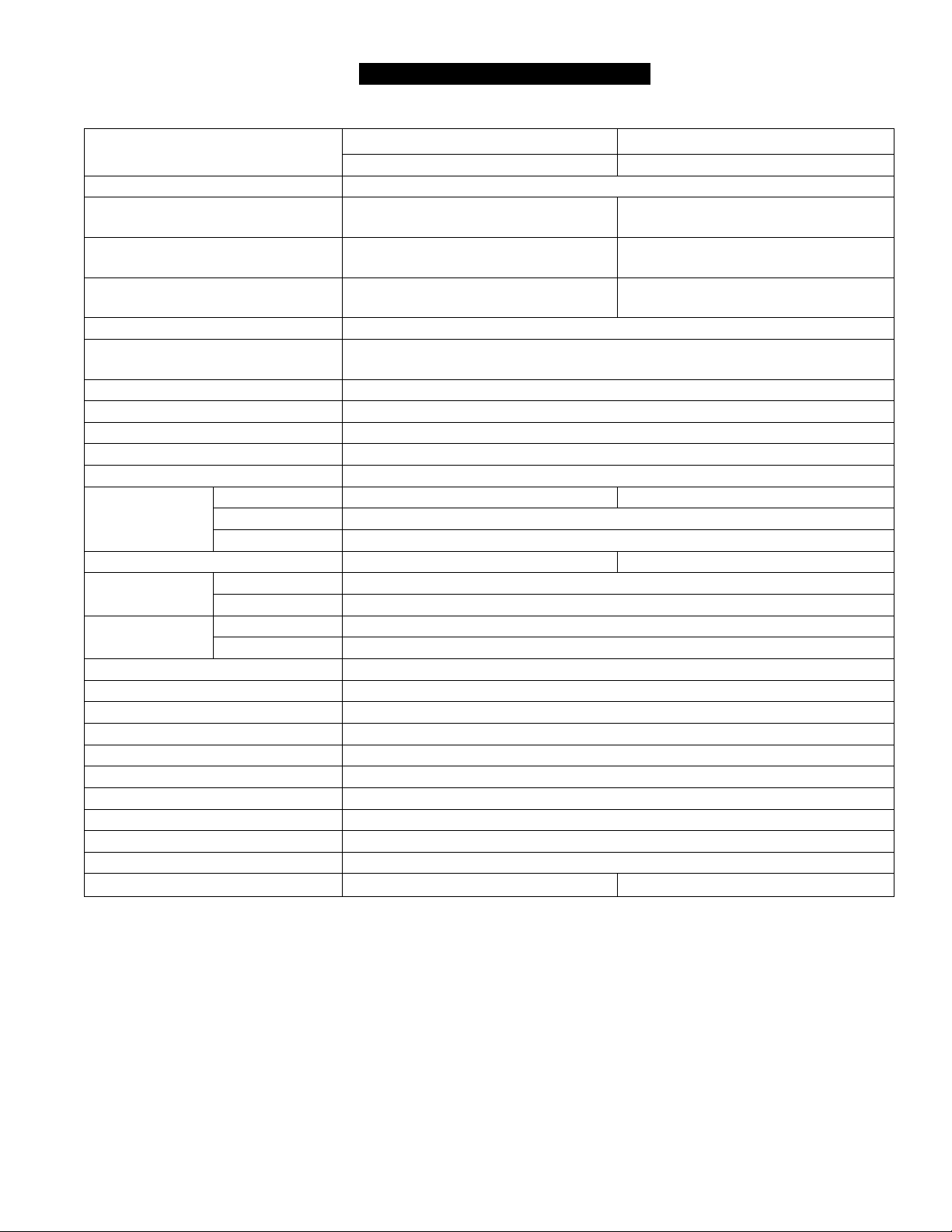
MODEL
Minimum gas consumption btu/h 15,000
Maximum gas consumption btu/h 180.000 Natural Gas
Hot water capacity (Min - Max) * 0.6 - 7.5 GPM
Hot water capacity (45°F rise) 6.6 GPM (25.0 L/min) 7.4 GPM (28.0 L/min) Natural Gas
Defauit Temperature Setting (no controiier) 120° F (49° C)
Temperature Controiier Defauit Temperature
Setting
Maximum Temp Setting (Residential) Selectable at 120° F (49° C) or at 140° F (60° C)
Minimum Temperature Setting 98° F (37° C)
Weight 50 lb (22.7 kg)
Efficiency Rating 84%
Noise Level 49 dB
Electrical
Consumption
By-Pass Control Fixed Electronic
Minimum Gas
Supply Pressure
Maximum Gas
Supply Pressure
Type of Appliance Direct Vent, Temperature controlled continuous flow gas hot water system
Operation With Or Without Temperature Controls, Mounted In Kitchen, Bathroom, Etc.
Approved Gas Type Natural Gas Or Propane - Ensure Unit Matches Gas Type It’s Being Installed On.
Connections Gas Supply: 3/4" Mnpt, Cold Water Inlet: 3/4" Mnpt, Hot Water Outlet: 3/4"
Ignition System Direct Electronic Ignition
Electric Connections Appliance: Ac 120 Volts, 60hz. Temperature Control: Dc 12 Volts (Digital)
Water Temperature Control Simulation Feedforward And Feedback.
Water Supply Pressure Minimum Water Pressure: 20 Psi (Recommended 30-80 Psi For Maximum Performance)
Maximum Water Supply Pressure 150 PSI
Temperature Control Cable Non-Polarized Two Core Cable (Minimum 22 Awg)
Energy Star Qualified Yes Yes
Normal 65 W 79 W
Standby 2.0 W
Anti-Frost Protection 100 W
Natural Gas 5.0 inch W.C.
Propane 8.0 inch W.C.
Natural Gas 10.5 inch W.C.
Propane 13.5 inch W.C.
305 Models 505 Models
154.330020 & 154.330030 154.330060 & 154.330070
199.000 Natural Gas
180.000 Propane Gas
(2.3 - 28.4 L/min)
104° F (40° C)
190.000 Propane Gas
0.6-9.4 GPM
(2.3 - 35.5 L/MIN)
7.1 GPM (26.9 L/min) Propane Gas
* Minimum flow may vary slightly depending on the temperature setting and the inlet water temperature.
Specifications are subject to change without prior notice.
The maximum inlet gas pressure must not exceed the value specified by the manufacturer. The minimum value listed
is for the purpose of input adjustment.
305 & 505 Indoor Manual
Page 8
-—-A——___
A I it>
_____
-
I
I
I
-
O
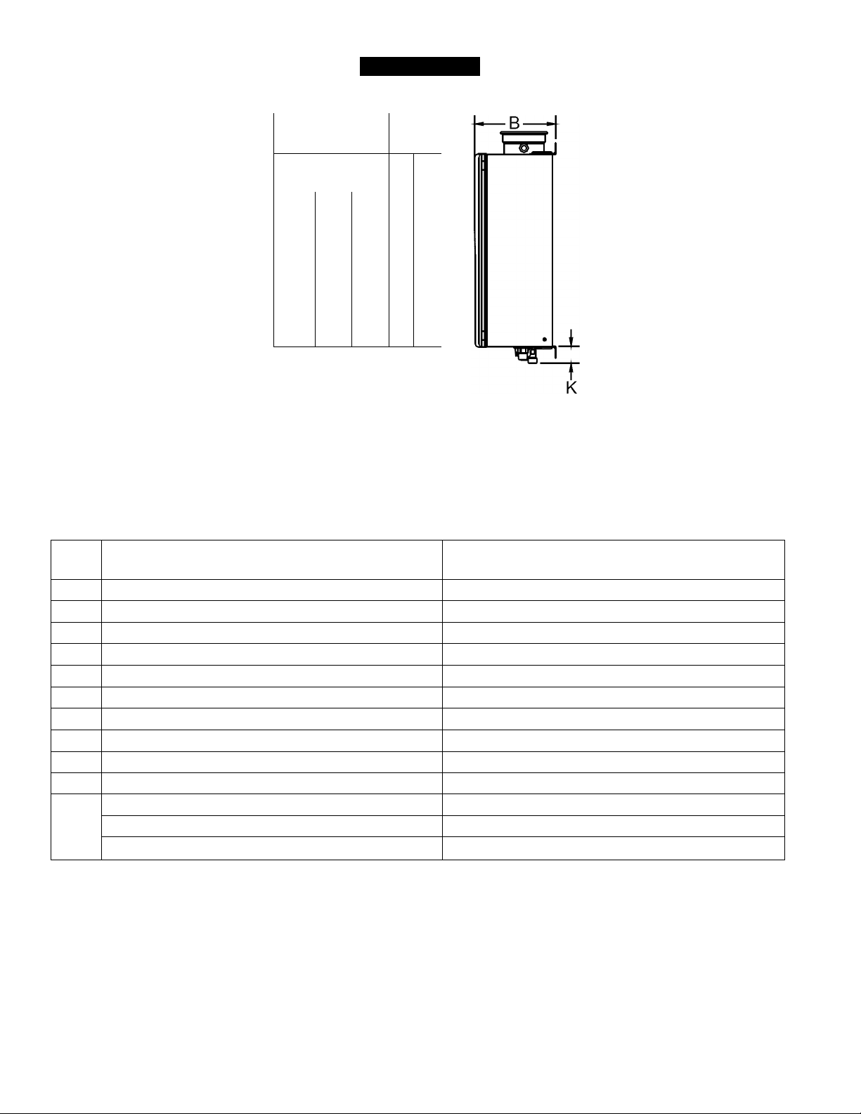
DIMENSIONS
-V
(
D
JB—
E-> H
G-* !■
F
DIM DESCRIPTION
A Width 14 (355.6)
B Depth * 9.6 (244.5)
C Height - Unit 22.9 (582)
D Height - with brackets 25.5 (648.2)
E Hot Water Outlet - from wall * 3.6 (91)
F Hot Water Outlet - from center 4.3 (109)
G Cold Water Inlet - from wall * 2.8 (70)
H Cold Water Inlet - from center 1.1 (27)
I Gas Connection - from wall * 4.3 (109)
J Gas Connection - from center 3.5 (89)
From base to gas connection 1.6 (40)
K From base to cold connection 2.0 (50)
From base to hot connection 1.6 (41)
* This is the minimum dimension from the wall. The wall bracket is adjustable to allow an additional 1.57 inches (40 mm).
305 & 505 Series
in. (mm)
305 & 505 Indoor Manual
Page 9
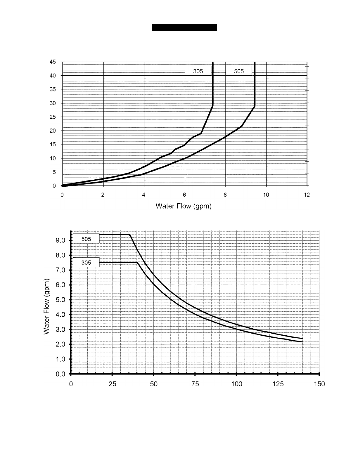
Pressure Drop Curve
V)
w
w
o
_l
CD
13
CD
CD
CD
TECHNICAL DATA
100
90
80
70
60
50
40
30
20
10
0
T3
JZ
_l
CD
CD
CD
CD
o
CD
U.
13
CO
CO
0
Outlet Flow Data
delta T - Temperature Rise (°F)
305 & 505 Indoor Manual
Page 10
INSTALLATION INSTRUCTIONS
Only properly trained and qualified installers should
install this appliance. The warranty may be voided due
to improper installation or installation by a non-qualified
installer.
General Instructions
A WARNING
Do not use substitute materials.
Use only parts certified with the appliance.
This appliance must be installed by a state qualified or
licensed contractor. It is the responsibility of the person
having the water heater installed to ensure the installing
contractor has proper licenses and permits for installing
water heaters in your location. It is highly recommended
that installers attend a product knowledge class to
ensure customer satisfaction and warranty coverage.
Failure to comply with state and local codes pertaining
to water heater installations may void the warranty.
This appliance is not to be installed outdoors.
A qualified installer or service technician should install
the appliance, inspect it, and leak test it before use.
The installation must conform with local codes or, in
the absence of local codes, with the National Fuel Gas
Code, ANSI Z223.1/NFPA 54, or the Natural Gas and
Propane Installation Code, CSAB149.1.
The appliance, when installed, must be electrically
grounded in accordance with local codes or, in the
absence of local codes, with the National Electrical
Code, ANSI/NFPA70, or the Canadian Electrical Code,
CSA C22.1.
The appliance and its appliance main gas valve must be
disconnected from the gas supply piping system during
any pressure testing of that system at test pressures in
excess of 1/2 psi (3.5 kPa) (13.84 in W.C.).
The appliance must be isolated from the gas supply
piping system by closing its individual manual shutoff
valve during any pressure testing of the gas supply
piping system at test pressures equal to or greater than
1/2 psi (3.5 kPa) (13.84 in W.C.).
The appliance should be located in an area where
water leakage of the unit or connections will not
result in damage to the area adjacent to the appliance
or to lower floors of the structure. When such locations
cannot be avoided, it is recommended that a suitable
metal drain pan, adequately drained, be installed under
the appliance. The pan must not restrict combustion air
flow.
The flow of combustion and ventilation air shall not be
obstructed.
It is highly recommended that all installers attend a
product knowledge class.
• This appliance is not suitable for use in an application
such as a pool or spa heater that uses chemically
treated water. (This appliance is suitable for filling large
or whirlpool bath tubs with potable water.)
• As water is heated, it expands (thermal expansion). In
a closed system, the volume of water will grow. As the
volume of water grows, there will be a corresponding
increase in water pressure due to thermal expansion.
Thermal expansion can cause premature tank failure
(leakage). This type of failure is not covered under the
limited warranty. Thermal expansion can also cause
intermittent pressure relief valve operation: water
discharged from the valve due to excessive pressure
build up. The pressure relief valve is not intended for
the constant relief of thermal expansion. This condition
is not covered under the limited warranty.
A properly-sized thermal expansion tank should be
installed on all closed systems to control the harmful
effects of thermal expansion. Contact a plumbing service
agency or your retail supplier regarding the installation
of a thermal expansion tank. NOTE: Reference Figures
3-6 to see if your installation recommends the use of a
thermal expansion tank.
• Should overheating occur or the gas supply fail to
shut off, turn off the manual gas control valve to the
appliance.
• Keep the air intake location free of chemicals such as
chlorine or bleach that produce fumes. These fumes
can damage components and reduce the life of your
appliance.
Clearances from Appliance
10 305 & 505 Indoor Manual
Page 11

Table 1:
Top of 6 inches 2 inches
Heater (152 mm) (51 mm)
Back of
Heater
Front of 6 inches 6 inches
Heater (152 mm) (152 mm)
Sides of 2 inches 1/2 inches
Heater (51 mm) (13 mm)
Floor/ 12 inches 12 inches
Ground (305 mm) (305 mm)
Vent 0 (zero) 0 (zero)
to Combustibles to Non-Combustibles
305/505 305/505
0 (zero) 0 (zero)
The clearance for servicing is 24 inches in front of the
water heater.
For closet installation: clearance is 6 inches (152 mm)
from the front.
Attachment of the Water Heater
wall Installation
' brackets
n-
Figure 2
1. Ic
Identify the installation location and confirm that the
installation will meet all required clearances.
2. Securely attach the water heater to the wall using any
of the holes in the wall installation brackets which are
at the top and bottom of the water heater. Ensure that
the attachment strength is sufficient to support the
weight. Refer to the weight of the water heater in the
Specifications section.
General Instructions
A manual gas control valve must be placed in the gas
supply line to the water heater. A union can be used on
the connection above the shut off valve for the future
servicing or disconnection of the unit.
Check the type of gas and the gas inlet pressure before
connecting the water heater. If the water heater is not of
the gas type that the building is supplied with, DO NOT
connect the water heater. Contact Sears for the proper
unit to match the gas type.
Check the gas supply pressure immediately upstream
at a location provided by the gas company. Supplied
gas pressure must be within the limits shown in the
Specifications section.
Before placing the appliance in operation all joints
including the heater must be checked for gas tightness
by means of leak detector solution, soap and water, or
an equivalent nonflammable solution, as applicable.
Electrical Connection
The water heater requires a standard 3 prong 120 VAC,
60 Hz properly grounded wall outlet. Plug the 6 ft long
power cord into the wall outlet.
GAS SUPPLY
(Since some leak test solutions, including soap and
water, may cause corrosion or stress cracking, the
piping shall be rinsed with water after testing, unless it
has been determined that the leak test solution is non
corrosive.)
Always use approved connectors to connect the unit
to the gas line. Always purge the gas line of any debris
before connection to the water heater.
The gas supply line shall be gas tight, sized, and so
installed as to provide a supply of gas sufficient to meet
the maximum demand of the heater and all other gas
consuming appliances at the location without loss of
pressure.
Any compound used on the threaded joint of the gas
piping shall be a type which resists the action of liquefied
petroleum gas (propane / LPG).
Refer to an approved pipe sizing chart if in doubt about
the size of the gas line.
305 & 505 Indoor Manual 11
Page 12
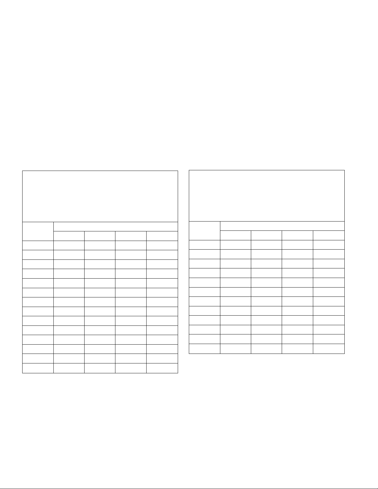
Pipe Sizing Procedure - Example
The gas supply must be capable of handling the entire gas load at the location. Gas line sizing is based on gas type,
the pressure drop in the system, the gas pressure supplied, and gas line type. Refer to the National Fuel Gas Code,
NFPA54, for proper gas line sizing. The below information is provided as an example.
1. Determine the cubic feet per hour of gas required by dividing the gas input (on the rating plate) by the heating value
of the gas (available from the local gas company). The gas input needs to include all gas products at the location
and the maximum BTU usage at full load when all gas products are in use.
Gas Input of the water heater (BTU / HR)
Cubic Feet per Hour (CFH) = ----------------------------------------------------------
Heating Value of Gas (BTU / FT 3 )
2. Use the table for your gas type to find the pipe size required for your cubic feet per hour of gas and your pipe
length.
Example: The heating value of natural gas for your location is 1020 BTU/FP
The gas input is 199,000 BTU/HR. Additional appliances at the location require 75,000 BTU/HR.
Therefore the cubic feet per hour = (199,000 + 75,000) / 1020 = 268.6 FP/HR.
If the pipe length is 100 ft then the 1 % inch pipe size capable of supplying 304 FP/HR of natural gas will
be adequate.
TABLE 2: Pipe Sizing Table - Natural Gas
cubic feet per hour Schedule 40 Metallic Pipe
Inlet Pressure: less than 2 psi (55 inches W.C.)
Pressure Drop: 0.3 inches W.C.
Specific Gravity: 0.60
Length
3/4 1 1 1/4 1 1/2
Pipe Size (inches)
10 273 514 1060 1580
20 188 353 726 1090
30 151 284 583 873
40 129 243 499 747
50 114 215 442 662
60 104 195 400 600
70 95 179 368 552
80 89 167 343 514
90 83 157 322 482
100 79 148 304 455
125 70 131 269 403
150 63 119 244 366
175 58 109 224 336
200 54 102 209 313
TABLE 3: Pipe Sizing Table - Propane Gas
cubic feet per hour Schedule 40 Metallic Pipe
Inlet Pressure: 11 inches W.C.
Pressure Drop: 0.5 inches W.C.
Specific Gravity: 1.50
Length
1/2 3/4 1 1 1/4
Pipe Size (inches)
10 291 608 1150 2350
20 200 418 787 1620
30 160 336 632 1300
40 137 287 541 1110
50 122 255 480 985
60 110 231 434 892
80 101 212 400 821
100 94 197 372 763
125 89 185 349 716
150 84 175 330 677
175 74 155 292 600
200 67 140 265 543
12 305 & 505 Indoor Manual
Page 13

WATER PIPING
General Instructions
• A manual water control valve must be placed in the
water inlet connection to the water heater before it is
connected to the water line. Unions may be used on
both the hot and cold water lines for future servicing
and disconnection of the unit.
• The piping (including soldering materials) and
components connected to this appliance must be
approved for use in potable water systems.
• Purge the water line to remove all debris and air.
Debris will damage the water heater.
• Toxic chemicals such as those used for boiler water
treatment are not to be introduced to the potable
water used for space heating.
• If the appliance will be used as a potable water
source, it must not be connected to a system that
was previously used with a nonpotable water heating
appliance.
• Ensure that the water filter on the water heater is clean
and installed (See Flushing the Heat Exchanger).
Pressure Relief Valve
• An approved pressure relief valve is required by the
American National Standard (ANSI Z21.10.3)/Canadian
Standard (CSA 4.3) for all water heating systems.
• The relief valve must comply with the standard for Relief
Valves and Automatic Gas Shutoff Devices for Hot Water
Supply Systems ANSI Z21.22 and /or the standard
Temperature, Pressure, Temperature and Pressure
Relief Valves and Vacuum Relief Valves, CAN1-4.4.
• The relief valve must be rated up to 150 psi and to at
least the maximum BTU/hr of the appliance.
• The discharge from the pressure relief valve should
terminate a maximum of six inches above a floor
drain or external to the building. In cold climates, it is
recommended that the discharge pipe be terminated
at an adequate drain inside the building. Follow local
codes. Water discharged from the relief valve could
cause severe burns instantly, scalds, or death.
• The pressure relief valve must be manually operated
once a year to check for correct operation.
• The relief valve should be added to the hot water outlet
line according to the manufacturer’s instructions. DO
NOT place any other type valve or shut off device
between the relief valve and the water heater.
• Do not plug the relief valve and do not install any
reducing fittings or other restrictions in the relief line
The relief line should allow for complete drainage of the
valve and the line.
• If a relief valve discharges periodically, this may be due
to thermal expansion in a closed water supply system.
Contact the water supplier or local plumbing inspector on
how to correct this situation. Do not plug the relief valve.
* •
• Neither this water heater nor the American National
Standard (ANSI Z21.10.3) / Canadian Standard (CSA
4.3) requires a combination temperature and pressure
relief valve for this appliance. However, local codes
may require a combination temperature and pressure
relief valve.
Freezing Protection
The freeze protection features include electrical heating
elements and intermittent firing of the burner. Freeze
protection may be disabled if electricity or gas is not
supplied, or if there is an error preventing the water
heater from functioning. Loss of freeze protection may
result in water damage from a burst heat exchanger or
water lines.
The installation of auto drain down solenoid valves is
optional. However, it is strongly recommended that
these valves be installed to prevent damage from
freezing in case the normal freeze protection should
become disabled. Any product damage due to freezing
will not be covered by the warranty.
In addition, the solenoid valves should be connected
electrically to a surge protector with terminals that
attaches to the PC board in the unit. This allows the
solenoid valves to operate if the water heater is disabled
due to an error code.
The solenoid valves and the surge protector with
terminals are available for purchase separately.
NOTICE: Warranty does not cover damage due to
freezing.
When electrical power and gas are supplied to the
water heater, it will not freeze in environments as cold
as -30° F when protected from direct wind exposure.
In the event of a power failure at temperatures below
freezing the water heater should be drained of all water
to prevent freezing damage.
The unit may be drained manually. However, it is highly
recommended that drain down solenoid valves be
installed that will automatically drain the unit if power is
lost. It is also recommended that a surge protector with
terminals be installed that attaches to the PC board in
the unit and allows the solenoid valves to operate if the
unit is disabled due to an error code.
When the electrical power to the water heater fails, the
3/4” solenoid valve closes (stopping the flow of water
into the heater) and the 1/2” solenoid valve opens
(allowing the water heater and associated piping to
drain. Ensure that you run the drain for the solenoids to
the outside environment to prevent discharging water
inside the building causing water damage).
305 & 505 Indoor Manual 13
Page 14
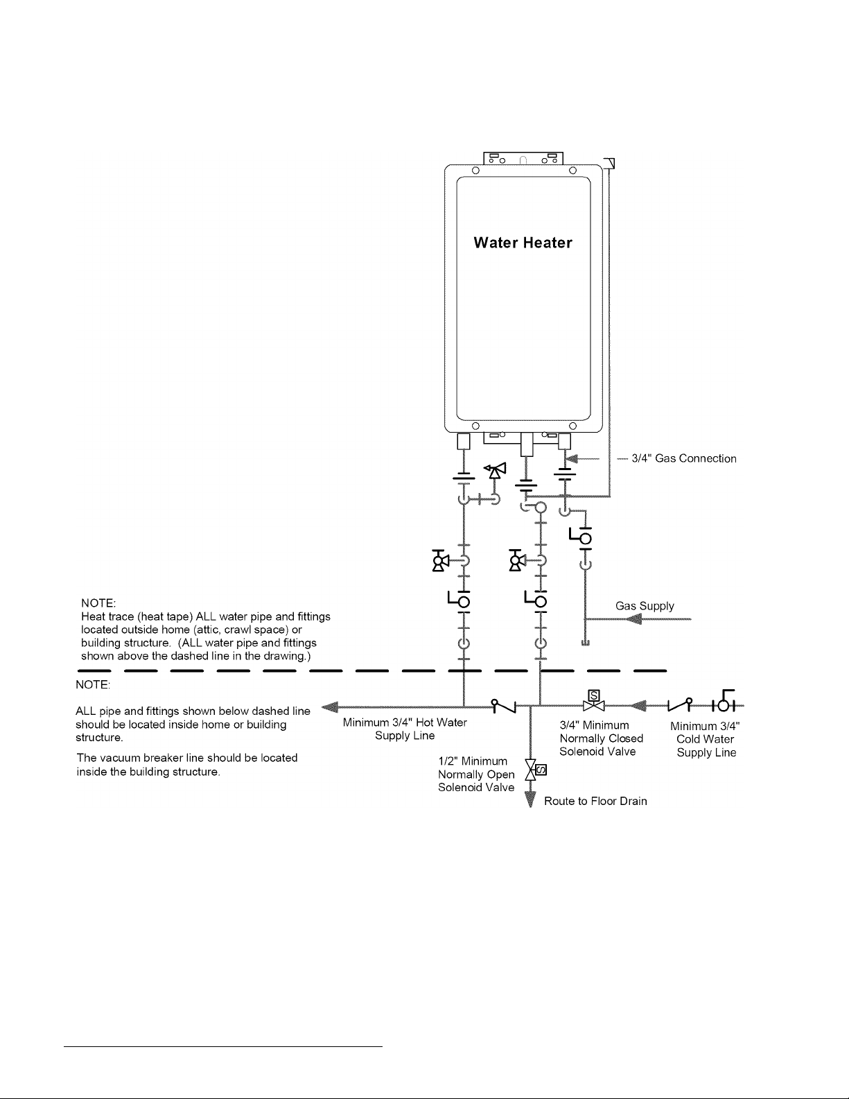
Figure 3: Freeze Protection Piping - Drawing
Vacuum
Breaker
KEY
3/4" Ball Valve
I il
3/4" Union
Check Valve
Pressure Relief Valve
14 305 & 505 Indoor Manual
Pressure Regulator
s
Circulating Pump
Boiler Drain Valve
Solenoid Valve
ft
This is not an engineered drawing. It is intended only as a guide and not
as a replacement for professionally engineered project drawings. This
drawing is not intended to describe a complete system. It is up to the
contractor/engineer to determine the necessary components and
configuration of the particular system being installed. This drawing does
not imply compliance with local building code requirements. It is the
responsibility of the contractor/engineer to ensure installation is in
accordance with all local building codes. Confer with local building
officials before installation.
Page 15
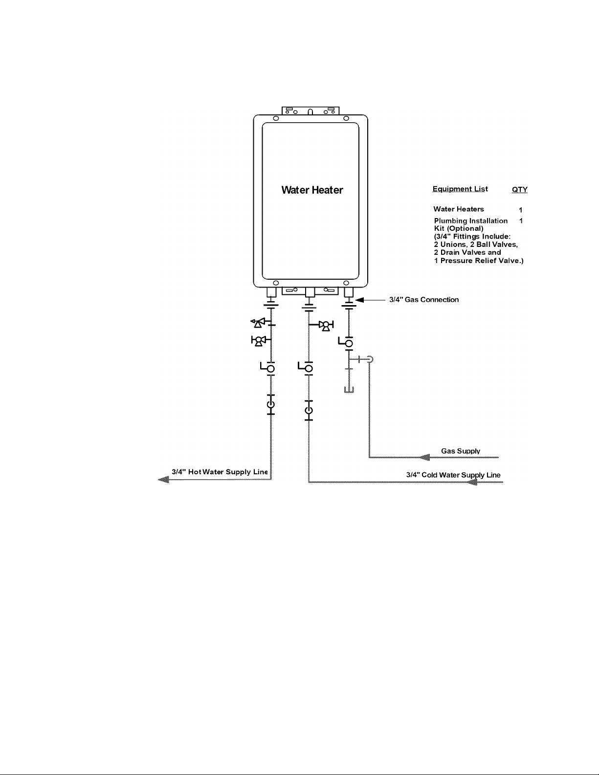
Figure 4: Recommended Piping for Basic Installation
I 3/4" Ball Valve
3/4" Union
Check Valve
Pressure Relief Valve
For Building Fixtures
KEY
Pressure Regulator
Circulating Pump
Boiler Drain Valve
Solenoid Valve
This is not an engineered drawing. It is intended only as a guide and not
as a replacement for professionally engineered project drawings. This
drawing is not intended to describe a complete system. It is up to the
contractor/engineer to determine the necessary components and
configuration of the particular system being installed. This drawing does
not imply compliance with local building code requirements. It is the
responsibility of the contractor/engineer to ensure installation is in
accordance with all local building codes. Confer with local building
officials before installation.
305 & 505 Indoor Manual 15
Page 16

Figure 5: Recommended Piping for Circulation Systems
NOTE:
Applications, using this piping
arrangement maintains fuli
warranty.
For this application:
Pump should be controlled by an Aqua-
stat, Timer or Combination Aquastat and
Timer.
Pump to be sized to maintain circulation
loop temperature.
The pump should be sized to overcome
the pressure loss through the tank water
heater, and supply and return plumbing.
Pump to be of bronze or stainless
construction.
^
____
f o
I °o n o'^ I
Water Heater
Lq
Lq
_____
-p Gas Supply
+
Equipment List
Water Heaters
Plumbing Installation
Kit (Optional)
(3/4" Fittings Include:
2 Unions, 2 Ball Valves,
2 Drain Valves and
1 Pressure Relief Valve
3/4" Gas Connection
QTY
o
IMPORTANT: Connect the building
return line to the hot water supply line
as close as possible to the water
heater.
KEY
3/4" Ball Valve
—
3/4" Union
Check Valve
Pressure Relief Valve
16 305 & 505 Indoor Manual
Pressure Regulator
s
Circulating Pump
Boiler Drain Valve
Solenoid Valve
eft
o
Tank Water Heater to be Sized for
Heat Loss of Circulation Loop.
This is not an engineered drawing. It is intended only as a guide and not
as a replacement for professionally engineered project drawings. This
drawing is not intended to describe a complete system. It is up to the
contractor/engineer to determine the necessary components and
configuration of the particular system being installed. This drawing does
not imply compliance with local building code requirements. It is the
responsibility of the contractor/engineer to ensure installation is in
accordance with all local building codes. Confer with local building
officials before installation.
Minimum 3/4" Cold Water Sup^ Line
Electric Water
Heater
-M!—^-\ÒÌ-
Building Supply
7T
Building
Fixtures
Expansion Tank
Page 17
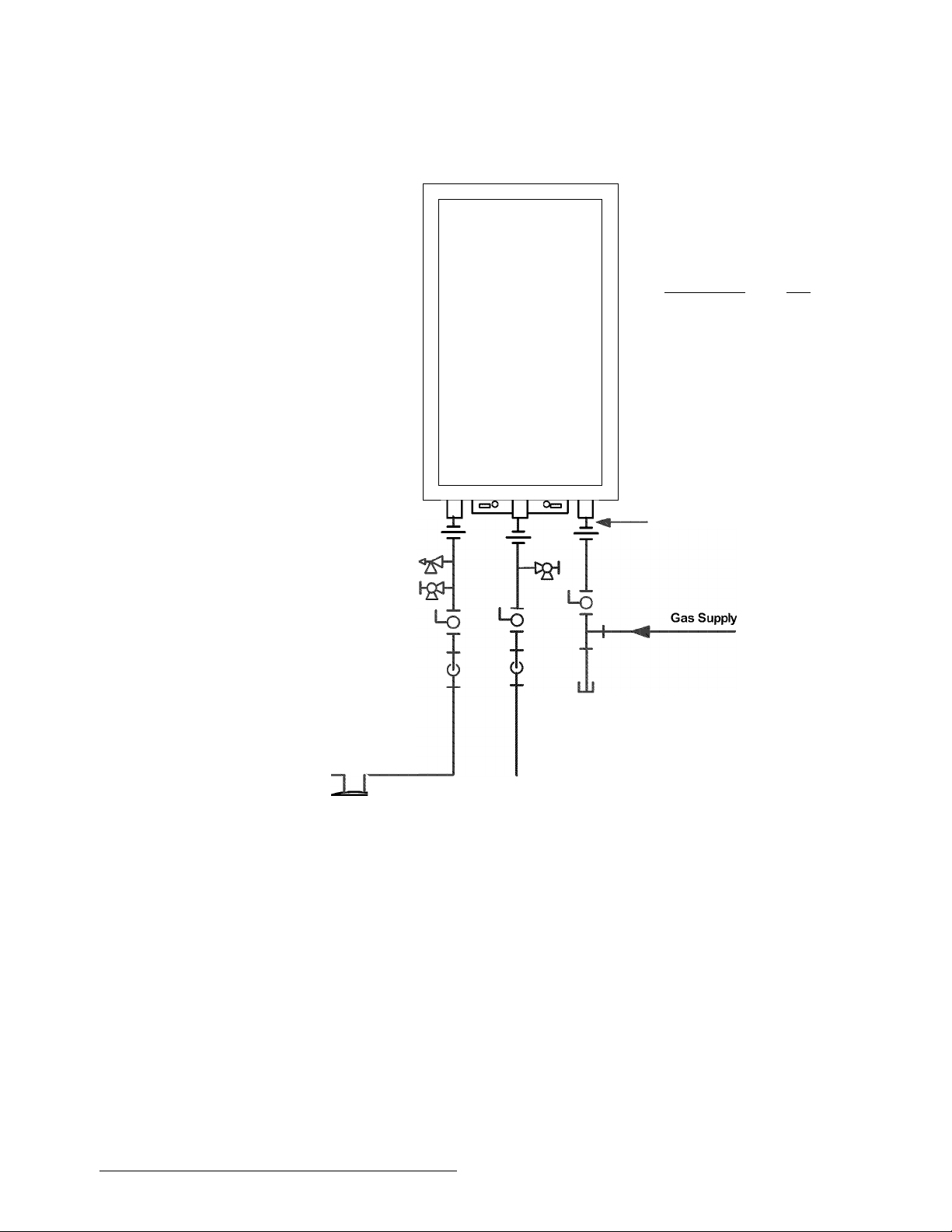
Figure 6: Optional Piping for Circulation Systems
NOTE:
Applications, using this piping
arrangement reduces the
warranty to the following:
3 years on heat exchanger
3 year on parts
Full warranty will be maintained if an
on-demand recirculation system in
incorporated. Refer to the Limited
Warranty.
For this application:
Pump should be controlled by an Aquastat,
Timer or Combination Aquastat and Timer.
Pump to be sized to maintain circulation
loop temperature.
A minimum of 3 GPM flow is recommended
for the circulation system.
The pump should be sized to overcome the
pressure loss through the water heater,
supply and return plumbing.
Pump to be of bronze or stainless construe
tion.
I °o n o° I
o o
r s
Water Heater
o o
\
N
Equipment List QTY
Water Heaters 1
Plumbing Installation 1
Kit (Optional)
(3/4" Fittings Include:
2 Unions, 2 Ball Valves,
2 Drain Valves and
1 Pressure Relief Valve.)
-
/
3/4" Gas Connection
Note:
Water heater outlet temperature
cannot be adjusted when
circulation pump is running.
Building Fixture Outlets
3/4" Ball Valve
3/4" Union
Check Valve
Pressure Relief Valve
Minimum 3/4" Hot Water
Supply Line
rm
KEY
Pressure Regulator
s
Circulating Pump
m
Boiler Drain Valve
fgj
Solenoid Valve
[ft
Minimum 3/4“ Cold Wbter Supply Une
(Optional)
2-6 Gallon
Storage Tank
(To eliminate cold water
sandwich effect caused by
frequent On/Off operation)
This is not an engineered drawing. It is intended only as a guide and not
as a replacement for professionally engineered project drawings. This
drawing is not intended to describe a complete system. It is up to the
contractor/engineer to determine the necessary components and
configuration of the particular system being installed. This drawing does
not imply compliance with local building code requirements. It is the
responsibility of the contractor/engineer to ensure installation is in
accordance with all local building codes. Confer with local building
officials before installation.
305 & 505 Indoor Manual 17
Expansion Tank
Page 18
VENTING INSTRUCTIONS
Intake / Exhaust Guidelines
Refer to the specific instructions on your vent product
or additional installation requirements.
• This water heater is a direct vent water heater and
therefore is certified and listed with the vent system. You
must use vent components that are certified and listed
with the water heater model.
• Do not combine vent components from different
manufacturers.
• The vent system must vent directly to the outside of the
building and use outside air for combustion.
• Venting should be as direct as possible with a minimum
number of pipe fittings.
• Avoid dips or sags in horizontal vent runs by installing
supports per the vent manufacturer’s instructions.
• Support horizontal vent runs every four feet and all
vertical vent runs every six feet or in accordance with
local codes.
• Vent diameter must not be reduced.
• Do not connect the venting system with an existing vent
or chimney.
• Do not common vent with the vent pipe of any other
water heater or appliance.
• Vent connections must be firmly pressed together so
that the gaskets form an air tight seal.
• On the 305 and 505 models, the vent piece connected to
the water heater must be secured with one self-tapping
screw.
• Refer to the instructions of the vent system manufacturer
for component assembly instructions.
• If the vent system is to be enclosed, it is suggested
that the design of the enclosure shall permit inspection
of the vent system. The design of such enclosure shall
be deemed acceptable by the installer or the local
inspector.
NOTICE: If it becomes necessary to access an enclosed
vent system for service or repairs, the manufacturer is
not responsible for any costs or difficulties in accessing
the vent system. Warranty does not cover obtaining
access to an enclosed vent system.
Condensate
A WARNING
If the condensate collector is not used, the drain pipe must
be capped to prevent exhaust gases and condensate from
entering the buiiding. The cap is suppiied on the appiiance.
Condensate formation can occur in high efficiency direct
vent appliances. To prevent condensate damage follow
these instructions.
18
305 & 505 Indoor Manual
NOTICE: Provisions must be made to prevent the
condensate from entering the water heater. Without
proper drainage or disposal, condensate will damage
the heat exchanger.
• Vertical terminations must incorporate a condensate
drain and trap as close as possible to the appliance.
• Slope any horizontal venting 1/4 inch per foot (19 mm
/ m), towards the heater if the condensate collector is
used, or towards the exhaust terminal if the condensate
collector is not used.
• Dispose of condensate per local codes.
• The condensate trap must contain a minimum of 3 inches
(75 mm) of water.
• This water heater has an integrated condensate
collector.
• Regions of cold climate will create more condensate in
the vent system. The condensate collector should be
used in cold climates.
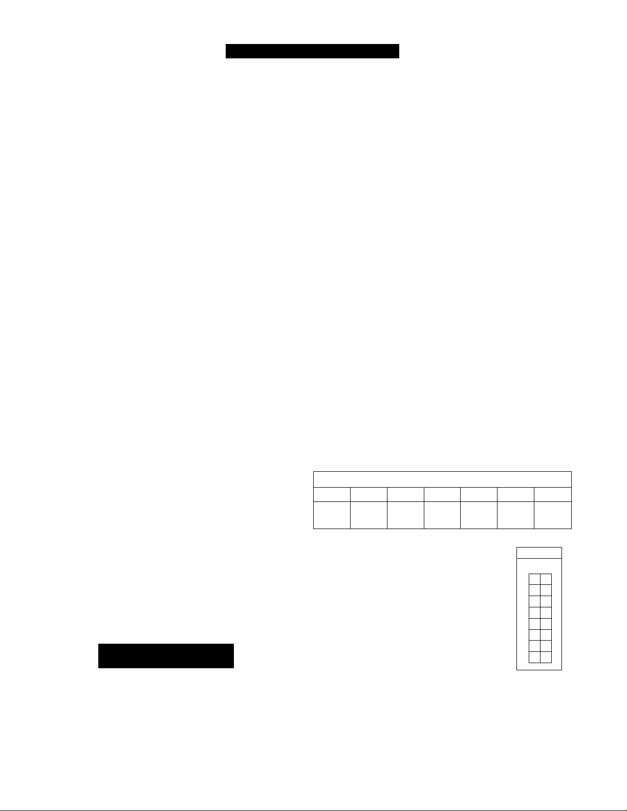
Maximum Vent Length
1. Determine the number of 90 degree elbows in the vent
system. (Two 45 degree elbows count as one 90 degree
elbow.)
2. Refer to the table to find the maximum vent iength based
on the number of elbows.
3. Follow the applicable note.
Example: If you have one elbow then your maximum
vent iength is 35 feet (10.7 m). If your actual length is
greater than 15 ft (4.6 m) then move dip switch no. 1
(SW1) to OFF.
Table 4: Number of 90° Elbows
0 1 2 3 4 5 6
41 ft®
(12.5 m)
©
21 ft (6.4 m) then move dip
switch no. 1 (SW1) to OFF.
@
If the length is greater than
switch no. 1 (SW1) to OFF.
® If the length is greater than 9 ft
(2.7 m) then move dip switch
no. 1 (SWI)toOFF.
@ Move dip switch no. 1 (SW1)
to OFF.
NOTICE: If you have a longer
vent length, dip switch no. 1
is required to be in the OFF position. This ensures the
water heater will run properly. Blocked flue error codes
and shutdowns may result if dip switch no. 1 is not in
the correct position. On the 505 model, the maximum
water flow capacity will be reduced by about 10% when
dip switch no. 1 is OFF.
35 ft®
(10.7 m)
29 ft®
(8.8 m)
23 ft®
(7.0 m)
If the length is greater than
15 ft (4.6 m) then move dip
17 ft®
(5.2 m)
Notes
®©@©-
Fiaure 7
11 ft®
(3.4 m)
Switch No.
.0
F
F
■
5 ft®
(1.5 m)
ON
1
2
3
4
5
6
7
8
Page 19
VENTING PRODUCTS
Table 5: Listed and Tested Vent Products for the 305 and 505 Models
Manufacturer Product Parts
Ubbink Rolux Vent System
Heat-Fab Saf-T Vent SC system
Metal-Fab Corr/Guard Vent/Air Intake System
Vent Manufacturer Contact Information for Installation Instructions and Parts Lists:
Ubbink Heat-Fab Metal-Fab Inc.
Telephone: 866-677-4960 Telephone: 800-772-0739 Telephone: 800-835-2830
500 Tennessee Waltz Parkway Fax: 413-863-4803 316-943-2351
Ashland City, TN 37015 E-mail: [email protected] Fax: 316-943-2717
Web Site: www.heatfab.com E-mail: [email protected]
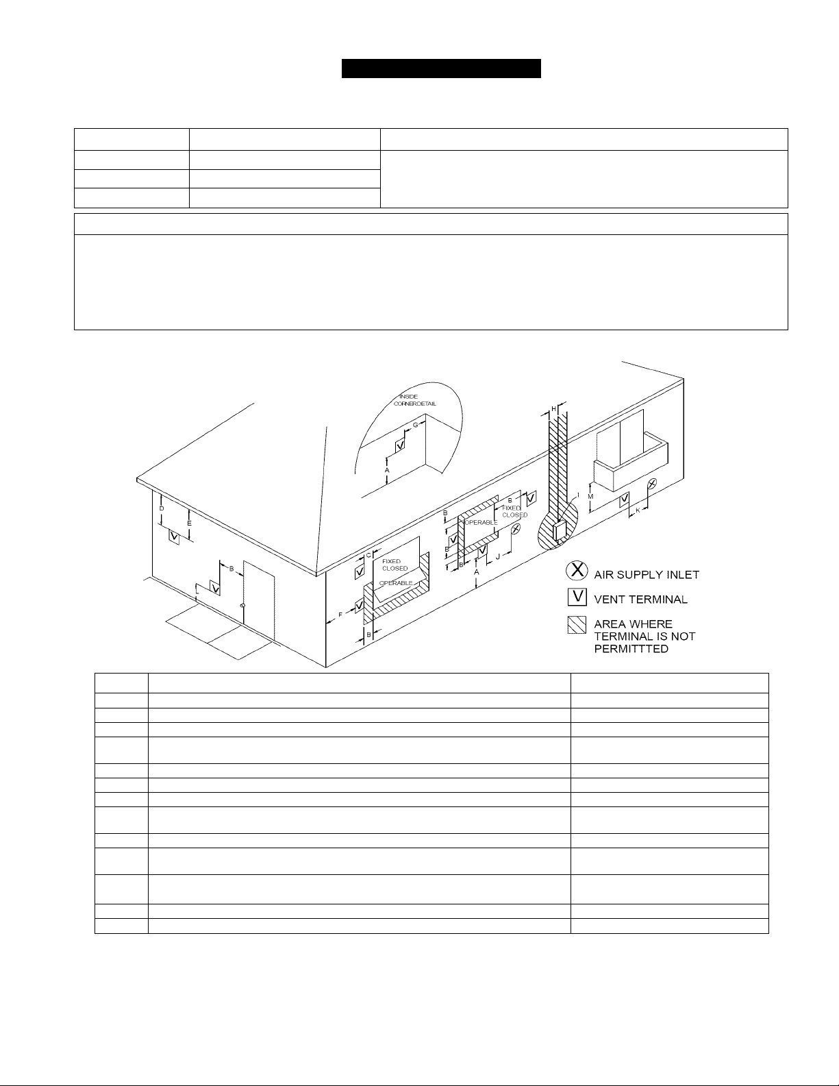
Figure 8: Flue Terminal Clearances (ANSI Z21.10.3 • CSA 4.0)
Refer to the manufacturer’s technical literature for specific part numbers and
instructions.
Web Site:
www.metal-fabinc.com
Ref Description US Installations
A Clearance above grade, veranda, porch, deck, or balcony 12 inches (30 cm)
B Clearance to window or door that may be opened 12 inches (30 cm)
C Clearance to permanently closed window
D Vertical clearance to yentilated soffit, located aboye the terminal within a
horizontal distance of 2 feet (61 cm) from the center line of the terminal
E Clearance to unyentilated soffit
F Clearance to outside corner
G Clearance to inside corner
H Clearance to each side of center line extended aboye meter/regulator
assembly
I
Clearance to seryice regulator yent outlet
J Clearance to nonmechanical air supply inlet to building or the combustion air
inlet to any other appliance
K
Clearance to a mechanical air supply inlet
L Clearance aboye payed sidewalk or payed driyeway located on public property
M Clearance under yeranda, porch, deck, or balcony
© A vent shall not terminate directly above a sidewalk or paved driveway that is located between two single family dwellings and serves
both dwellings.
© Permitted only if veranda, porch, deck, or balcony is fully open on a minimum of two sides beneath the floor.
* For clearances not specified in ANSI Z223.1/NFPA 54 or CSA B149.1, clearances are in accordance with local installation codes and the
requirements of the gas supplier.
305 & 505 Indoor Manual 19
12 inches (30 cm)
3 feet (91 cm) aboye if within
10 feet (3 m) horizontally
*
*
*
*
*
*
*
*
*
Page 20

Additional Clearance - Vent Terminal
Local codes supersede these clearances.
• Avoid termination locations near a dryer vent.
• Avoid termination locations near commercial cooking exhaust.
Vent terminal (represents concentric vent terminal for the water heater)
(1.52 m) vertically
60"
between water heater
terminals
(V)
(0.61 m) to wall or parapet
24"
V
12"
(V)
(0.30 m) between water
heater terminals at same
level
Figure 9
20 305 & 505 Indoor Manual
Page 21
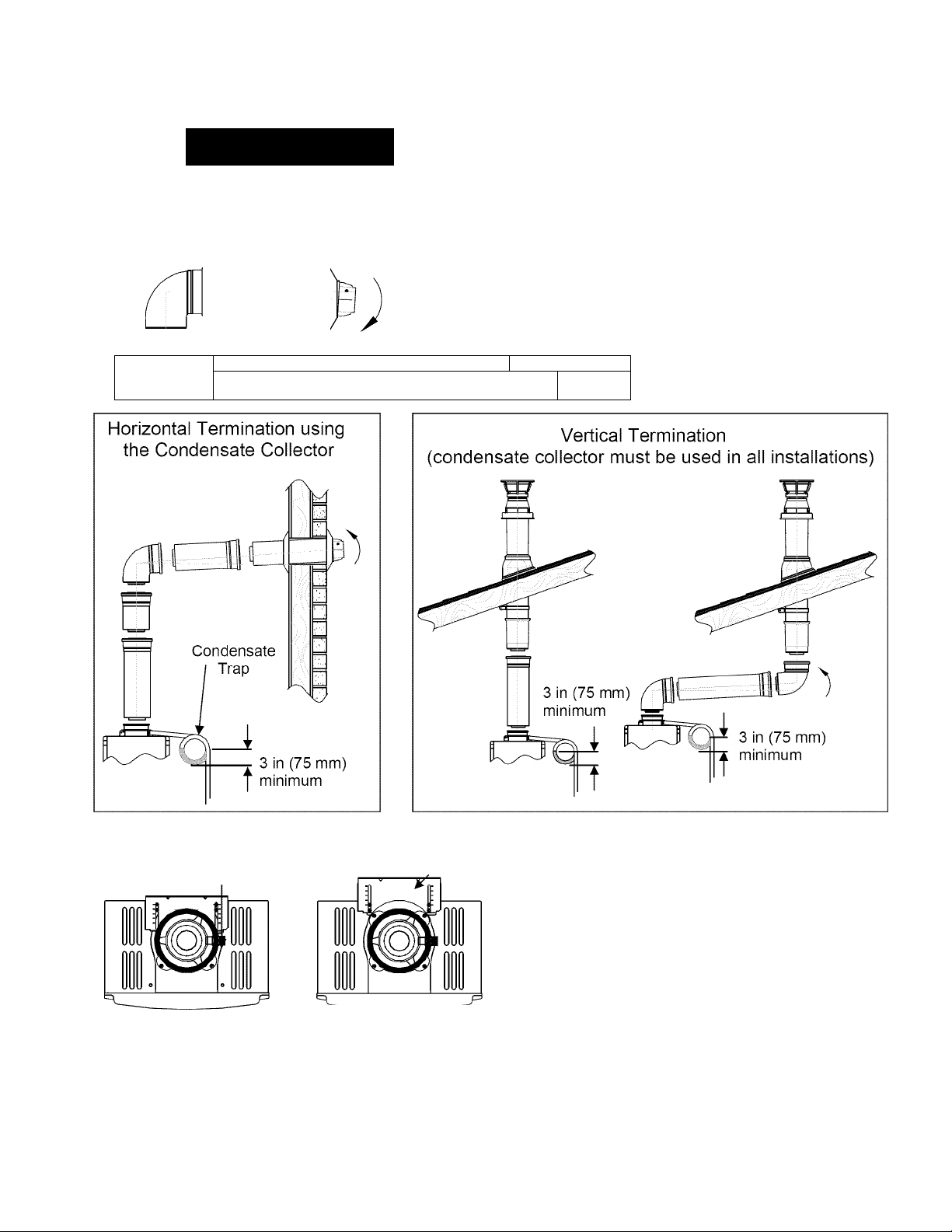
Flue Installation for the 305 and 505 Models
Horizontal Termination without using the Condensate Collector
A WARNING
If the condensate collector is not used, the drain pipe must
be capped to prevent exhaust gases and condensate from
entering the building. The cap is supplied on the appliance.
Maximum Height *
VI
* The condensate collector must be used
in horizontal terminations if a vertical rise
in the vent system exceeds 5ft.
5 feet (1.52 m)
r ^ ^
Regions of cold climate will create
more condensate in the vent system.
The condensate collector should be
used in cold climates.
If more than one elbow is used in the
vertical section the condensate
collector must be used.
Condensate Collector
11
To adjust the condensate collector position or to
Bracket
replace the female vent top with a male vent top:
1. Loosen the 4 screws at the rear bracket
2. Slide the bracket away from the female vent top.
3. Remove the 4 screws attaching the female vent
top to the water heater.
4. Lift up the female vent top and reposition as
desired (or replace with a male vent top).
5. Install the 4 screws at the vent top and tighten the
4 screws at the bracket.
Securing Screw
Secure the first vent component to the water heater
with one self-tapping screw at the hole located above
the condensate collector.
Figure 10
305 & 505 Indoor Manual 21
Page 22
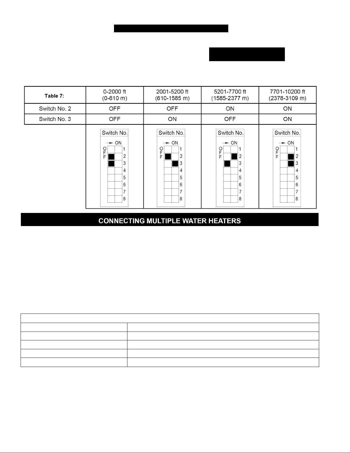
HIGH ALTITUDE INSTALLATIONS
Set dip switches 2 and 3 to the values shown in table
below for your altitude. The default setting for the
appliance is 0-2000 ft (0-610 m) with switches No. 2 and
No. 3 in the OFF position.
A WARNING
DO NOT adjust the other dip switches uniess specificaliy
instructed to do so.
The 2-Unit connection cable is an optional accessory
that connects 2 water heaters and allows them to
function as one hot water source.
The Multi-Unit connection kit and Multi-Unit connection
cables are optional accessories that connect 2 to 5
water heaters and allow them to function as one hot
water source.
The Multi-Unit connection kit includes a PC board and
one Multi-Unit connection cable.
Refer to the instructions that come with the accessory
for complete installation information.
Table 8:
Number of Connected Water Heaters: Accessories Necessary:
2 (1) 2-Unit connection cable or (1) Multi-Unit connection kit
3 (1) Multi-Unit connection kit and (1) Multi-Unit connection cable
4 (1) Multi-Unit connection kit and (2) Multi-Unit connection cables
5 (1) Multi-Unit connection kit and (3) Multi-Unit connection cables
Guidelines
• Do not install both the 2-Unit connection cable and the
Multi-Unit connection kit because they are not designed
to operate together.
• Water heaters should be installed less than 18 inches
apart so that the cables will reach between units and to
prevent temperature fluctuations (cold water sandwich
effect) when the water is shut off and turned back on.
• Temperature settings can only be changed on the
controller for the primary unit.
22 305 & 505 Indoor Manual
Page 23
TEMPERATURE CONTROLLER INSTALLATION
Location Mounting the Controller
Indoor models have their controller built into the front
panel. Additional controllers can also be installed.
• The controller should be out of reach of small
children.
• Avoid locations where the controller may become hot
(near the oven or radiant heater).
• Avoid locations in direct sunlight. The digital display may
be difficult to read in direct sunlight.
• Avoid locations where the temperature controller could
be splashed with liquids.
• Do not install in locations where it can be adjusted by
the public.
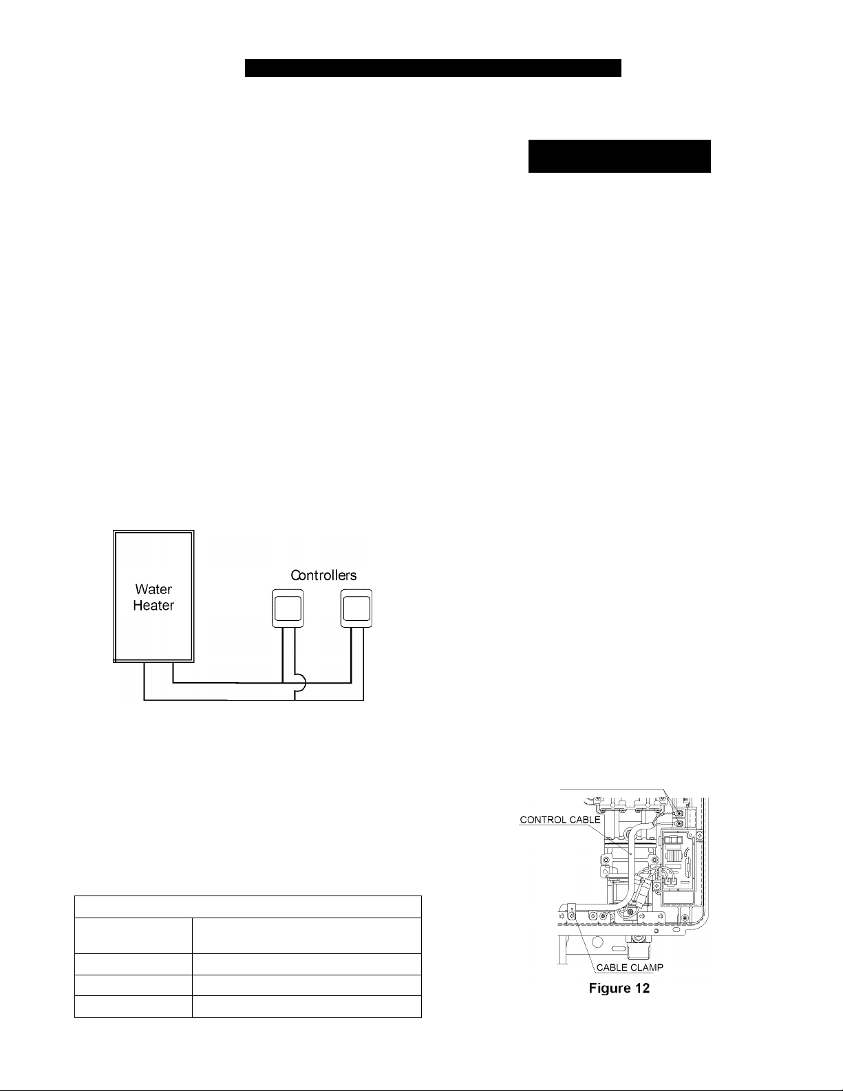
Configurations
A maximum of 4 temperature controllers can be installed
for a water heater or bank of water heaters.
Controllers can only be wired in parallel. Controllers
cannot be wired in series.
If 4 temperature controllers are installed, simultaneously
press the Priority and On/Off buttons on the fourth
controller until a beep sounds.
Do not attempt to connect the temperature controllers with
the power on. There is 120 volt potential, next to the
temperature controller connections inside the unit.
Do not connect the temperature controller to the 120VAC
terminals provided for the optional solenoid drain valves.
All service and wiring should be performed by a registered
installer.
Follow the procedure below to install additional
controllers.
1. Determine a suitable location for the controller.
2. Make three holes in the wall as shown.
3. Run the cable between the controller and the water
heater or the controller and the other controller.
4. Remove the face plate from the temperature controller
using a screwdriver.
5. Connect the cable to the temperature controller.
6. Mount the controller to the wall using the holes drilled
in step 2.
7. Disconnect the power from the water heater.
8. Remove the cover of the water heater.
9. Remove the plastic cover from the PCB and electrical
connections.
10. Thread the cable through the access hole at the base
of the unit and connect the wires to the controller
terminals on the right hand side bottom of the PCB.
11. Secure the controller cable using the clamp
provided.
12. Replace plastic cover over PCB and then replace the
cover of the water heater.
A WARNING
Outline of Controller
Wire controllers in parallel
Figure 11
Cable Length and Size
The cable for the temperature controller should be a
non-polarized two-core cable with a minimum gauge
of 22 AWG. The maximum cable length from each
controller to the water heater depends on the total
number of wired controllers connected to the water
heater.
Table 9:
Number of Wired
Controllers
1 328 ft (100 m)
2 164 ft (50 m)
3 or 4 65 ft (20 m)
Maximum Cable Length for each
Controller to Water Heater
305 & 505 Indoor Manual 23
securing screw
wiring hole
securing screw
CONNECTION TERMINALS
t
1-21/32"
t_
3-5/16
Page 24
DESCRIPTION OF OPERATION
This appliance is one of the most advanced water
heaters available. It provides a continuous supply of
hot water at a preset temperature. This appliance is
direct vent where air is brought in from the outside and
combustion gases are exhausted to the outside.
While electricity, water, and gas supplies are connected,
this appliance produces hot water whenever a hot water
tap is open.
Ignition is electronic. There is no pilot light consuming
gas while the water heater is not being used. The gas
burner lights automatically when the hot water tap is
OPERATING INSTRUCTIONS
Sequence of Operation
1. Water Flow Begins
• Water Flow Sensor sends a pulse to the electronic
control board
• Electronic control board senses flow greater than
0.6 GPM
• Firing Sequence begins
2. Firing Sequence
• Electronic control board monitors inlet/outlet water
temperature, temperature set point, and water
flow rate.
• Combustion fan energized. Purges combustion
chamber.
• Spark igniter begins sparking.
• Gas control valve opens to minimum fire rate.
• Flame rod proves ignition
• Spark igniter stops sparking
3. Normal Operation
• Electronic control board monitors flame rod,
fan motor frequency, outlet water temperature,
controller temperature set point and water flow
rate.
• Gas control valve modulates gas input to required
firing rate.
• Combustion fan speed is adjusted for the required
firing rate.
• Water flow control valve is adjusted as needed.
4. Shutdown Sequence
• Electronic control board senses water flow rate
less than 0.5 GPM.
• Gas control valve closes.
• Water flow control valve resets to standby
position.
• Combustion fan runs for a short period of time at
low speed.
5. Standby Mode
• Electronic control board monitors water temperature
and remote controls
• Freeze protection is activated as needed.
opened and goes out when the tap is closed. Installation
of the temperature controller is highly recommended.
The temperature controller can set the temperature
within a specific range and can provide error codes to
diagnose any problems.
The temperature of the outgoing hot water is constantly
monitored. This appliance may adjust the water flow
in order to maintain the temperature setting. The
water flow may vary from summer to winter due to the
difference in ground water temperature.
Features Available on Temperature Controllers
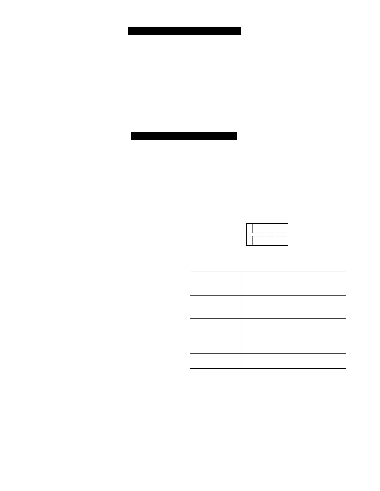
The temperature controller is supplied with the
appliance. Dimensions (inches): 3.5 W x 4.75 H x 0.75 D.
In Use
Indicator
Priority
Temperature
Display
Thermostat
u
—Hot water temp.
n
o Priority
On/Off
Features Description
Error Codes When a fault is detected an error code
In Use Indicator Indicates that hot water is being supplied
ON/OFF Button Used to turn the water heater ON or OFF.
Priority Button /
Indicator
Temperature Display Shows the temperature setting.
Thermostat Increases or decreases the temperature
flashes at the temperature
(i.e. a hot water tap is open).
Indicates that this controller is setting the
temperature . Priority can be switched to
another controller by pressing its Priority
Button when no hot water is running.
setting.
Figure 13
Indicator
Priority
Button
ON/OFF
Button
24 305 & 505 Indoor Manual
Page 25
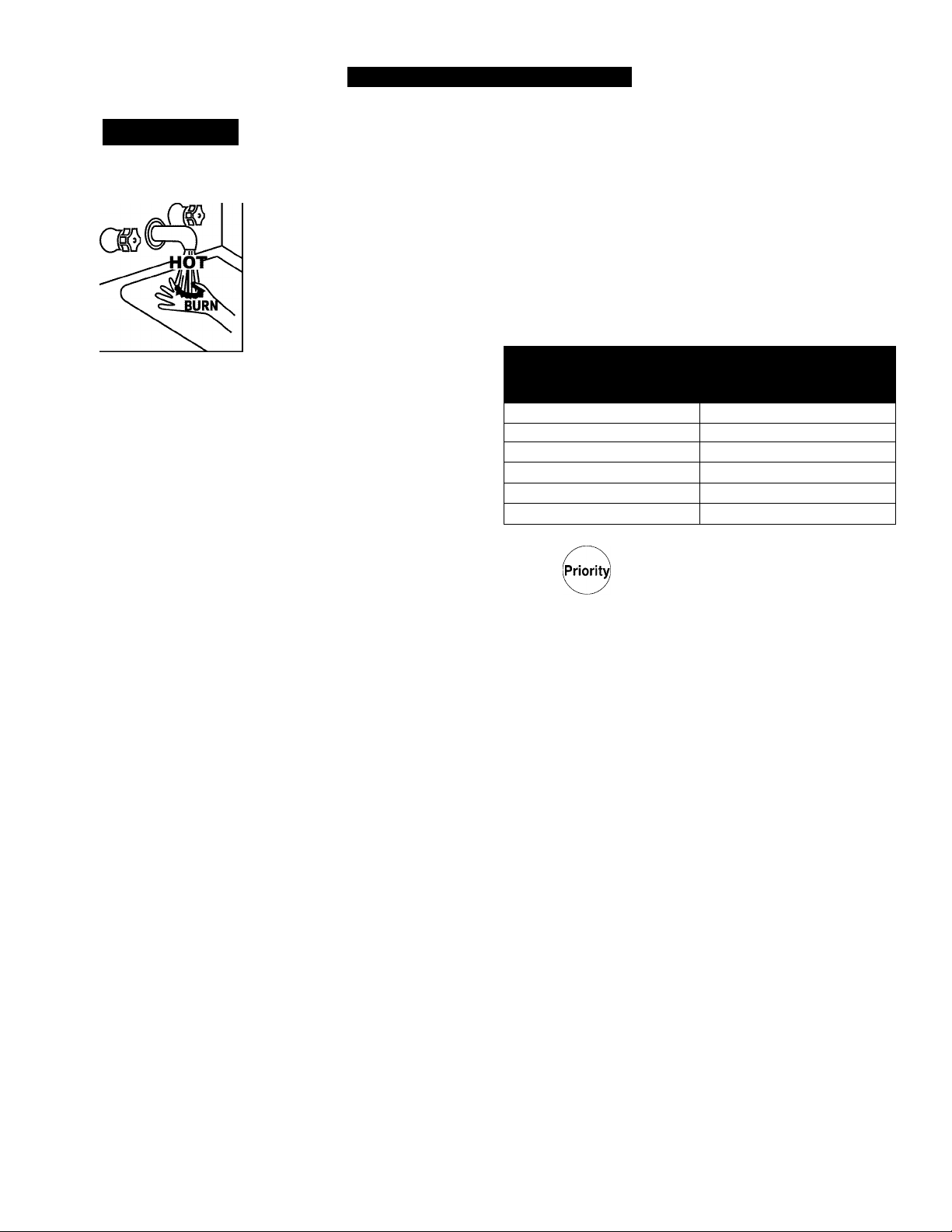
TEMPERATURE ADJUSTMENT
ÀDANGER
Water temperature over 125°F (52°C)
can cause servere burns instantly
resulting in severe injury or death.
Children, the elderly, and the
physically or mentally disabled are at
highest risk for scald injury.
Feel water before bathing or
showering.
Temperature limiting valves are
available.
Read instruction manual for safe
temperature setting.
For systems with storage tanks, the water temperature
in certain situation may vary up to 30°F (16.7°C) higher
or lower at the point of use such as, bathtubs,showers,
sink, etc.
HOTTER WATER CAN SCALD: Water heaters are
intended to produce hot water. Water heated to a
temperature which will satisfy space heating, clothes
washing, dish washing, and other sanitizing needs can
scald and permanently injure you upon contact. Some
people are more likely to be permanently injured by hot
water than others. These include the elderly, children,
the infirm, or physically/mentally handicapped. If anyone
using hot water in your home fits into one of these groups
or if there is a local code or state law requiring a certain
temperature water at the hot water tap, then you must
take special precautions. In addition to using the lowest
possible temperature setting that satisfies your hot water
needs, a means such as a mixing valve should be used
at the hot water taps used by these people or at the water
heater. Mixing valves are available at plumbing supply
or hardware stores. Follow manufacturer’s instructions
for installation of the valves. Before changing the factory
setting on the thermostat. Using the lowest hot water
temperature that meets your needs will also provide the
most energy efficient operation of the water heater.
Never allow small children to use a hot water tap, or
to draw their own bath water. Never leave a child or
handicapped person unattended in a bathtub or shower.
The thermostat on the water heater has been factory set
at 120°F, to reduce the risk of scald injury. It is adjustable
and can be reset to the desired temperature setting.
Some states have a requirement for a lower setting, if
you need hotter water, follow direction for temperature
adjustment, but beware of the warnings in this section.
NCTICE: While any hot water is being provided, the
temperature setting can only be adjusted between 98° F
and 110° F.
NCTICE: Check local codes for the maximum water
temperature setting allowed when used in nursing
homes, schools, day care centers, and all other public
applications.
NCTICE: If a newly installed unit with a temperature
controller has not been powered for at least 6 hours then
the temperature will return to the default setting of 104° F
(40° C) if power is interrupted.
NCTICE: There may be a variation between the
temperature displayed on the temperature controller and
the temperature at the tap due to weather conditions or
the iength of pipe to the water heater.
Table 10:
Temperature Settings
160°F (71°C) About 1/2 second
150°F (66°C) About 1-1/2 second
140°F (60°C)
130°F (54°C)
120°F (49°C)
80°F (27°C)
Time to Produce 2nd & 3rd
Degree Burns on Adult Skin
Less than 5 seconds
About 30 seconds
More than 5 minutes
1. Press the “Priority button”
C
on the temperature controller.
The green Priority iight will glow
indicating that this controller is
controlling the temperature and
that the water heater is ready to
supply hot water.
The priority can only be changed
while no hot water is running.
Press the A or T buttons to
obtain the desired temperature
W
Hot water temp.
setting.
All hot water sources are able to
provide water at this temperature
setting until it is changed again
M
at this or another temperature
controller.
305 & 505 Indoor Manual 25
Page 26
Temperature Ranges
This water heater will attempt to provide hot water at the temperature setting even when the water flow is varied or
when more than 1 tap is in use. The water heater can deliver water at only one temperature setting at a time. The
available temperatures for a given model are provided below.
Table 11:
Model Temperature Settings Available (°F)
305 Series
505 Series
Temp, in Celsius
98 100 102 104 106 108 110 115 120 125* 130* 135* 140*
98 100 102 104 106 108 110 115 120 125* 130* 135* 140*
37 38 39 40 41 42 43 46 49 52 54 57 60
* Re-setting the Maximum Temperature
Temperature settings from 125-140 °F (52-60 °C) are available by setting dip switch 6 to ON in the SW1 bank of 8
dip switches.
Table 12:
Suggested temperatures are: These temperatures are suggestions only.
Kitchen 120°F (49°C) A temperature lower than 98°F (37°C) can be obtained
Shower 98°- 110°F (37° - 43°C)
at the tap by mixing with cold water.
To change the temperature scale from Celsius to Fahrenheit or visa versa, press and hold the “On/Off” button for 5
seconds while the water heater is OFF.
Setting Controller to Mute
To eliminate the beeps when keys are pressed or to turn the beeps back on, press and hold both the A and T
buttons until a beep is heard (approximately 5 seconds).
26 305 & 505 Indoor Manual
Page 27
OPERATING YOUR WATER HEATER
FOR YOUR SAFETY READ BEFORE OPERATING
A WARNING
A. This appliance does not have a pilot. It is
equipped with an ignition device which
automatically lights the burner. Do not try to light
the burner by hand.
B. BEFORE OPERATING smell all around the
appliance area for gas. Be sure to smell next to
the floor because some gas is heavier than air and
will settle on the floor.
WHAT TO DO IF YOU SMELL GAS
• Do not try to light any appliance.
• Do not touch any electric switch; do not use any
phone in your building.
• Immediately call your gas supplier from a
neighbor’s phone. Follow the gas supplier’s
instructions.
If you do not follow these instructions exactly, a fire or explosion
may result causing property damage, personal injury or loss of life.
I OPERATING INSTRUCTIONS
1. STOP! Read the safety information above.
2. Set the thermostat to lowest setting.
3. Turn off all electric power to the appliance using
the ON/OFF button.
4. This appliance is equipped with an ignition device
which automatically lights the burner. Do not try to
light the burner by hand.
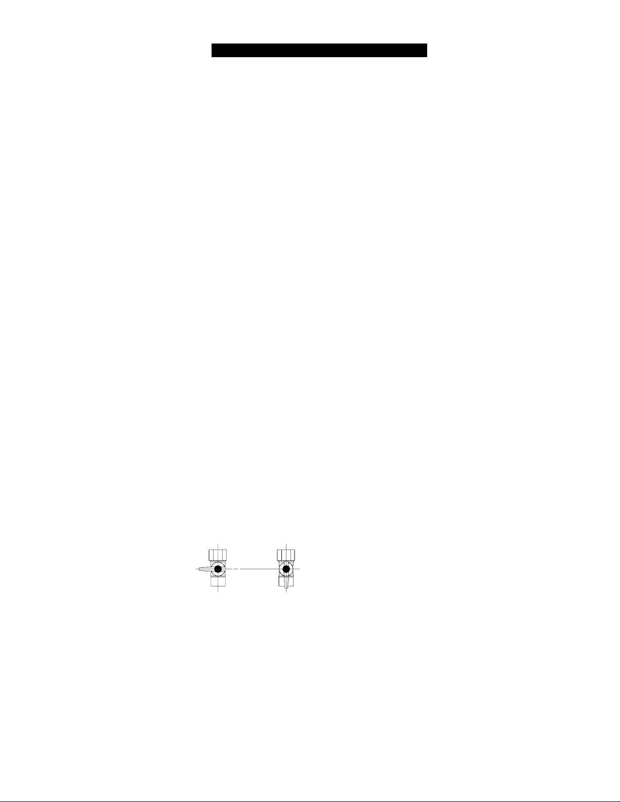
5. Locate the manual gas valve on the side of the
heater. Turn the manual valve
clockwise to the full OFF position.
Manual Valve
CLOSE OPEN
• If you cannot reach your gas supplier, call the
fire department.
C. Use only your hand to push in or turn the gas
control knob. Never use tools. If the knob will not
push in or turn by hand, do not try to repair it, call a
qualified service technician. Force or attempted
repair may result in a fire or explosion.
D. Do not use this appliance if any part has been
under water. Immediately call a qualified service
technician to inspect the appliance and to replace
any part of the control system and any gas control
which has been underwater.
.....................................
6. Wait five (5) minutes to clear out any gas. Then
smell for gas, including near the floor. If you smell
gas, STOP! Follow “B” in the safety information
above. If you don’t smell gas, go to the next step.
7. Turn the manual gas valve counterclockwise to the
full ON position.
8. Turn on all electric power to the appliance using
the ON/OFF button.
9. Set the thermostat to desired setting.
10. Open a hot water tap. If the appliance will not
operate, follow the instructions “To Turn Off Gas
To Appliance” and call your service technician or
gas supplier. See manual for additional
information.
....
I
/
TO TURN OFF GAS TO APPLIANCE
1. Turn off all electric power to the appliance using
the ON/OFF button.
2. Set the thermostat to lowest setting.
.......................
3. Locate the manual gas valve on the side of the
heater. Turn the manual valve clockwise to the full
OFF position.
305 & 505 Indoor Manual 27
........
Page 28
MAINTENANCE
Lime / Scale Build-up
A WARNING
Turn off the electrical power supply, the manual gas valve
and the manual water control valve whenever servicing the
unit.
Repairs and maintenance should be performed by a
qualified service technician. The appliance should be
inspected annually by a qualified service technician.
Verify proper operation after servicing.
Cleaning
It is imperative that control compartments, burners, and
circulating air passageways of the appliance be kept
clean.
Clean as follows:
1. Turn off and disconnect electrical power. Allow to
cool.
2. Remove and clean the water inlet filter.
3. Remove the front panel by removing 4 screws.
4. Use pressurized air to remove dust from the main
burner, heat exchanger, and fan blades. Do not
use a wet cloth or spray cleaners on the burner. Do
not use volatile substances such as benzene and
thinners. They may ignite or fade the paint.
5. Use soft dry cloth to wipe cabinet.
If you receive Error Code “LC”, refer to the procedure.
Flushing the Heat Exchanger. Refer to the section on
Water Quality to see if your water needs to be treated or
conditioned. (When checking maintenance code history,
“00” is substituted for “LC”.)
Snow Accumulation
Keep the area around flue terminal free of snow and ice.
The appliance will not function properly if the intake air
or exhaust is impeded (blocked or partially blocked) by
obstructions.
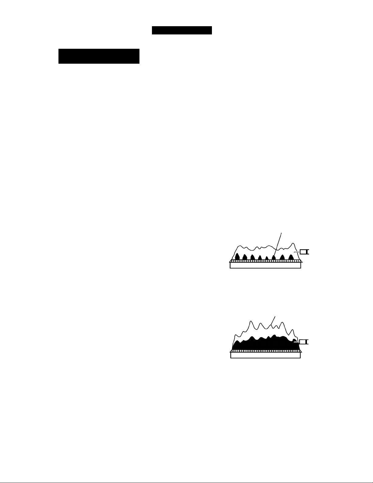
Visual Inspection of Flame
The burner must flame evenly over the entire surface
when operating correctiy. The flame must burn with a
clear, blue, stable flame. See the parts breakdown of the
burner for the location of the view ports.
The flame pattern should be as shown in the figures
beiow.
FRONT VIEW
SATISFACTORY
BLUE FLAME
FLAME ROD
Vent System
The vent system should be inspected at least annually
for blockages or damage.
Motors
Motors are permanently lubricated and do not need
periodic lubrication. Keep fan and motor free of dust and
dirt by cleaning annually.
Temperature Controller
Use a soft damp cloth to clean the temperature
controller. Do not use solvents.
UNSATISFACTORY
FRONT VIEW
YELLOW FLAME
FLAME ROD
Figure 14
28 305 & 505 Indoor Manual
Page 29

TROUBLESHOOTING
This appliance has the ability to check its own operation
continuously. If a fault occurs, an error code will flash
on the Display of the temperature controller. This
assists with diagnosing the fault and may enable you
to overcome a problem without a service call. Please
identify the code displayed when inquiring about service.
Table 13: Error Codes
Code Fault Remedy
02
10
11
12
No burner operation during freeze
protection mode
Air Supply or Exhaust Blockage Ensure approved venting materials are being used.
No Ignition Check that the gas is turned on at the water heater, gas meter, or cylinder.
Flame Failure Check that the gas is turned on at the water heater and gas meter. Check
Service Call - Check for possible freeze damage to heat exchanger.
Check that nothing is blocking the flue inlet or exhaust.
Check all vent components for proper connections.
Ensure vent length is within limits.
Ensure condensation collar was installed correctly.
Verify dip switches are set properly.
Check fan for blockage.
Ensure gas type and pressure is correct.
Ensure gas line, meter, and/or regulator is sized properly.
Bleed all air from gas lines.
Verify dip switches are set properly.
Ensure appliance is properly grounded.
Disconnect all 2-Unit or Multi-Unit connections to isolate the problem.
Ensure igniter is operational.
Check igniter wiring harness for damage.
Check gas solenoid valves for open or short circuits.
Remove burner cover and ensure all burners are properly seated.
Remove burner plate and inspect burner surface for condensation or debris.
for obstructions in the flue outlet.
Ensure gas line, meter, and/or regulator is sized properly.
Ensure gas type and pressure is correct.
Bleed all air from gas lines.
Ensure proper venting material was installed.
Ensure condensation collar was installed properly.
Ensure vent length is within limits.
Verify dip switches are set properly.
Ensure appliance is properly grounded.
Disconnect keypad.
Disconnect all 2-Unit or Multi-Unit connections to isolate the problem.
Check power supply for loose connections.
Check power supply for proper voltage and voltage drops.
Ensure flame rod wire is connected.
Check flame rod for carbon build-up.
Disconnect and reconnect all wiring harnesses on unit and PC board.
Check all components for electrical short.
Check gas solenoid valves for open or short circuits.
Remove burner plate and inspect burner surface for condensation or debris.
A WARNING
Some of the checks below may need to be done by a
qualified service technician. Call a service technician for any
remedy that involves gas or electricity. Call a service
technician if you have any doubt or reservation about
performing the remedy yourself.
305 & 505 Indoor Manual 29
Page 30
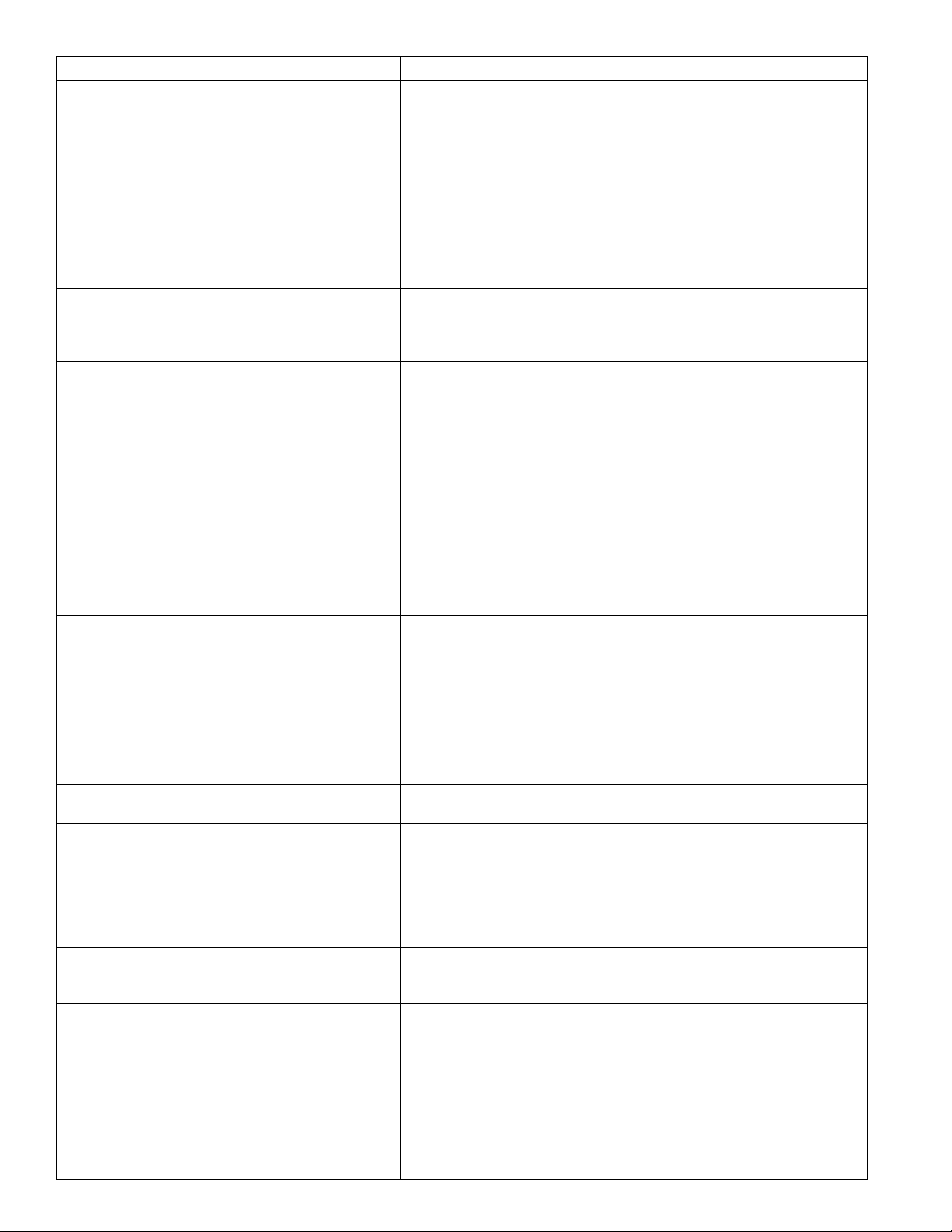
Code Fault Remedy
14
16
32
33
34
52
61
65
71
72
LC or
00
No
Code
30 305 & 505 Indoor Manual
Thermal Fuse Check gas type of unit and ensure it matches gas type being used.
Check for restrictions in air flow around unit and vent terminal.
Check for low water flow in a circulating system causing short-cycling.
Ensure dip switches are set to the proper position.
Check for foreign materials in combustion chamber and/or exhaust piping.
Check heat exchanger for cracks and/or separations.
Check heat exchanger surface for hot spots which indicate blockage due to
scale buildup.
Refer to instructions in manual for flushing heat exchanger.
Measure resistance of safety circuit.
Ensure high fire and low fire manifold pressure is correct.
Check for improper conversion of product.
Over Temperature Warning Check for restrictions in air flow around unit and vent terminal.
Check for low water flow in a circulating system causing short-cycling.
Check for foreign materials in combustion chamber and/or exhaust piping.
Check for clogged heat exchanger.
Outgoing Water Temperature Sensor
Fault
Heat Exchanger Outgoing Temperature
Sensor Fault
Combustion Air Temperature Sensor
Fault
Modulating Solenoid Valve Signal
Abnormal
Combustion Fan Failure Ensure fan will turn freely.
Water Flow Control Fault If blank screen is present on remote control then the flow control has
SVO, SV1, SV2, and SV3 Solenoid Valve
Circuit Fault
Flame Sensing Device Fault Ensure flame rod is touching flame when unit fires.
Scale Build-up in Heat Exchanger (when
checking maintenance code history, “00”
is substituted for “LC”)
Nothing happens when water flow is
activated.
Check sensor wiring for damage.
Measure resistance of sensor.
Clean sensor of scale build-up.
Replace sensor.
Check sensor wiring for damage.
Measure resistance of sensor.
Clean sensor of scale build-up.
Replace sensor.
Check for restrictions in air flow around unit and vent terminal.
Check sensor wiring for damage.
Measure resistance of sensor.
Clean sensor of scale build-up.
Ensure fan blade is tight on motor shaft and is in good condition.
Replace sensor.
Check modulating gas solenoid valve wiring harness for loose or damaged
terminals.
Measure resistance of valve coil.
Check wiring harness to motor for damaged and/or loose connections.
Measure resistance of motor winding.
shorted. Unplug flow control. If remote lights up and unit starts operating
then replace flow control assembly.
Check wiring harness to all solenoids for damage and/or loose connections.
Measure resistance of each solenoid valve coil.
Check all wiring to flame rod for damage.
Remove flame rod and check for carbon build-up; clean with sand paper.
Check inside burner chamber for any foreign material blocking flame at
flame rod.
Measure micro amp output of sensor circuit with flame present.
Replace flame rod.
Flush heat exchanger. See Flushing the Heat Exchanger section.
Clean inlet water supply filter.
Cn new installations ensure hot and cold water lines are not reversed.
Check for bleed over.
Isolate unit from building by turning off hot water line to building.
Isolate the circulating system if present. Cpen your pressure relief
valve; if water is flowing, there is bleed over in your plumbing.
Ensure you have at least the minimum flow rate required to fire unit.
Ensure turbine spins freely.
Measure the resistance of the water flow control sensor.
Check for DC shorts at components.
Page 31
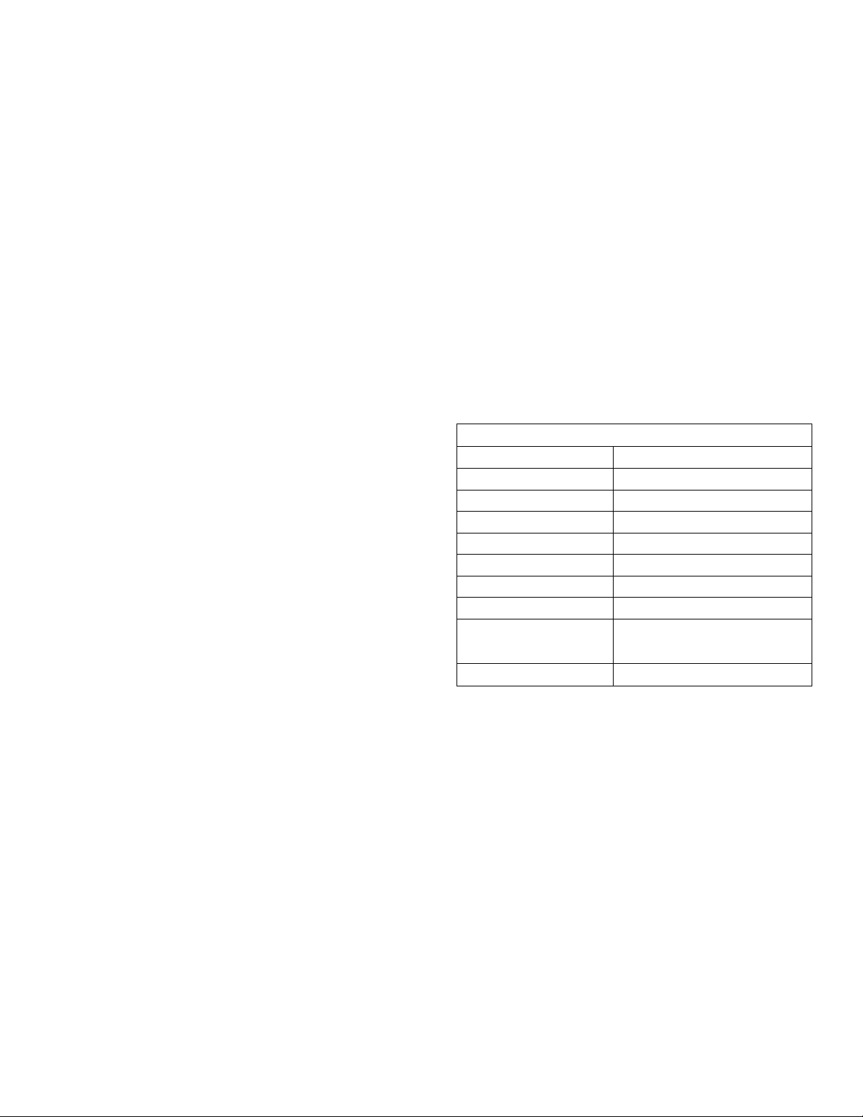
Troubleshooting for Common Issue
Accessing Operating Information
I don’t have any hot water when I open the tap.
Make sure there is gas, water, and electricity to the
water heater (power is turned on and the gas is turned
on).
When I was using the hot water, the water got cold.
If you adjusted the flow from the tap to lessen it, you
may have gone below the minimum flow required.
This water heater requires a minimum flow rate to
operate. (See the specification page for the flow rate of
your model.) Decrease the temperature setting at the
temperature controller or increase the water flow.
White smoke comes out of the exhaust.
During colder weather when the exhaust temperature
is much hotter than the outside air, the exhaust fumes
condense producing water vapor.
When I open a hot tap, I do not immediately get hot water.
Hot water must travel through your plumbing from the
water heater to the faucet. The time period for hot water
to reach your fixture is determined by the amount of
water in the plumbing system between the water heater
and the fixture, water pressure, and the flow rate of the
fixture.
After I turn off the hot water tap, the fan on the
water heater continues to run.
The fan is designed to continue running for a short time
after the flow of water stops. This is to ensure constant
water temperatures during rapid starting and stopping,
as well as exhausting any residual gas flue products
from the unit.
To display the most recent error codes press and hold
the “On/Off” button for 2 seconds. While holding the On/
Off” button press the A button. The last 9 error codes
will flash one after the other. To exit this mode press the
“On/Off” and A button as before.
To display the water flow through the water heater
press and hold the A button for 2 seconds and without
releasing the A button press the “On/Off button.
To display the outlet water temperature press and hold
the T button for 2 seconds and without releasing the T
button press the “On/Off” button.
Water Quality
Consideration of care for your water heater should
include evaluation of water quality. If the water quality
exceeds the target ievels provided in the table, you may
want to treat or condition the water.
* Source: Part 143 National Secondary Drinking Water
Regulations
Table 14:
Maximum Level
Total Hardness Up to 200 mg / L
Aluminum * Up to 0.2 mg / L
Chlorides * Up to 250 mg / L
Copper * Up to 1.0 mg / L
Iron * Up to 0.3 mg / L
Manganese * Up to 0.05 mg / L
pH * 6.5 to 8.5
TDS (Total Dissolved
Solids) *
Zinc * Up to 5 mg / L
Up to 500 mg / L
305 & 505 Indoor Manual 31
Page 32
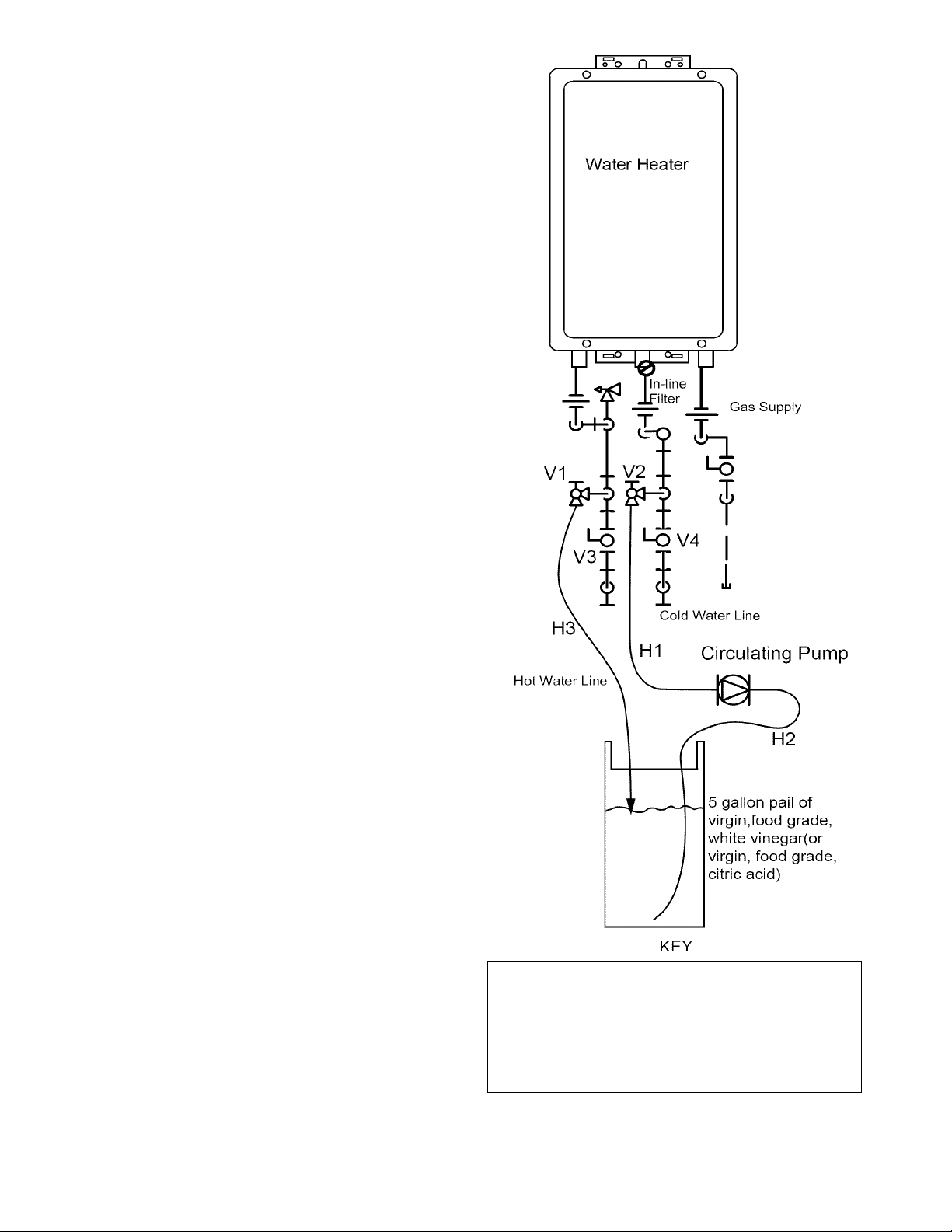
Flushing the Heat Exchanger (Error Code: LC or 00)
An “LC” or “00” error code indicates the unit is beginning
to lime up and must be flushed. Failure to flush the
appliance will cause damage to the heat exchanger.
Damage caused by lime build-up is not covered by the
unit’s warranty. After flushing, reset the LC fault code by
turning off the power to the unit and turning the power
back on.
1.
Disconnect electrical power to the water heater.
2.
Close the shutoff valves on both the hot water and
cold water lines (V3 and V4).
3.
Connect pump outlet hose (H1) to the cold water
line at service valve V2.
4.
Connect drain hose (H3) to service valve V1.
5.
Pour approximately 4 gallons of virgin, food grade,
white vinegar or citric acid into pail.
6.
Place the drain hose (H3) and the hose (H2) to the
pump inlet into the cleaning solution.
7.
Open both service valves (V1 and V2) on the hot
water and cold water lines.
8.
Operate the pump and allow the cleaning solution
to circulate through the water heater for at least 45
minutes.
9.
Turn off the pump.
a. Rinse the cleaning solution from the water
heater as follows: a. Remove the free end of the
drain hose (H3) from the pail.
b. Close service valve, (V2), and open shutoff
valve, (V4). Do not open shutoff valve, (V3).
c.d.Allow water to flow through the water heater for
5 minutes.
Close service valve, (V1), and open shutoff
valve, (V3).
10. Disconnect all hoses.
11. Remove the in-line filter at the cold water inlet and
clean out any residue. Place filter back into unit.
13. Restore electrical power to the water heater.
32 305 & 505 Indoor Manual
3/4" Ball Valve
3/4" Union Circulating Pump
Check Valve
Pressure Relief Valve
Figure 15
Pressure Regulator
s
Boiler Drain Valve
Solenoid Valve
eia
Page 33
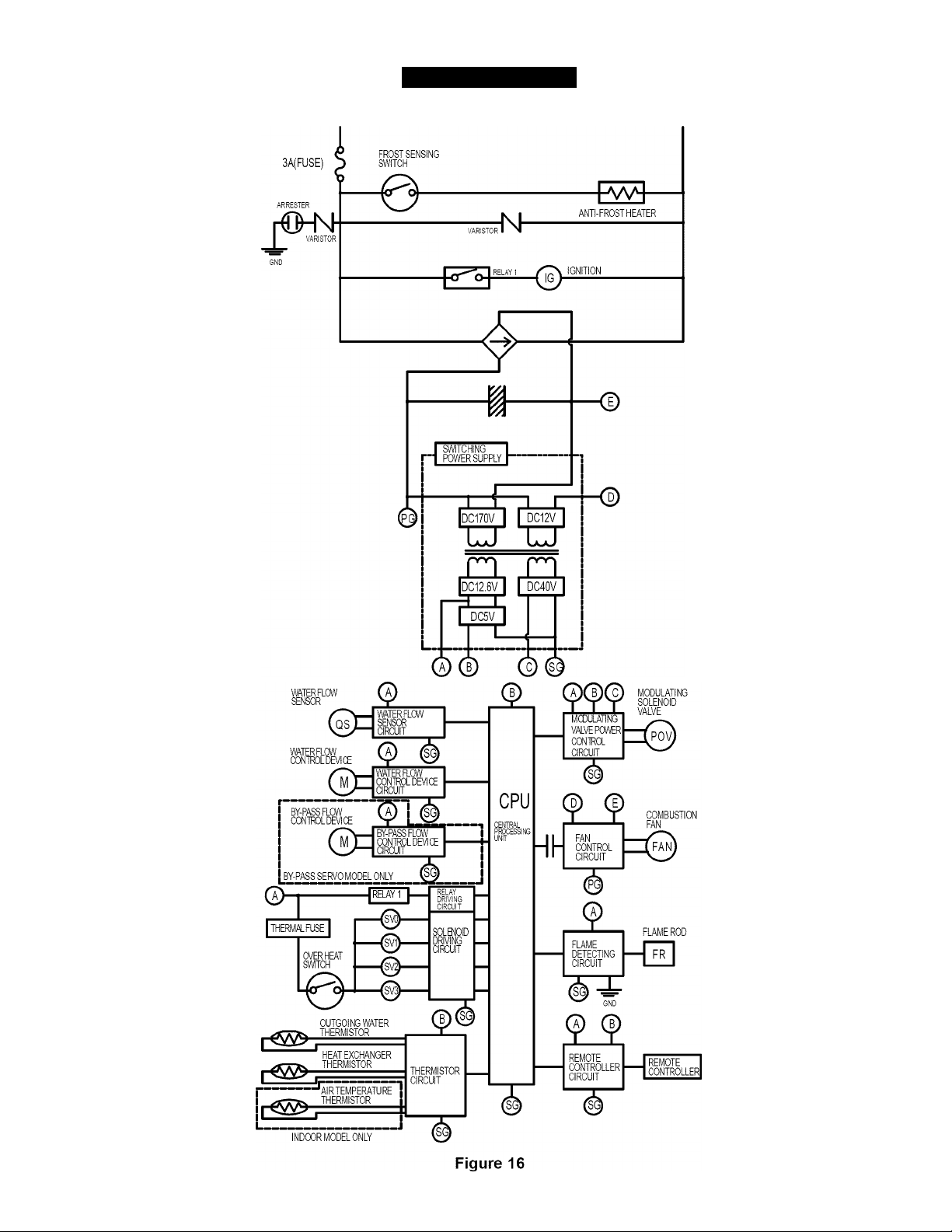
WIRING DIAGRAM
HOT
NEUTRAL
305 & 505 Indoor Manual 33
Page 34

SERVICE AND ADJUSTMENT
Contact Sears Service Center at: 1-800-4-MY-HOME® (1-800-469-4663).
For the convenience of the Qualified Service Technician a Technical Data Sheet has been placed inside the front
cover of the water heater. The Technical Data Sheet includes the following important information for Servicing and/or
Troubleshooting the water heater:
• Electric schematic (Wiring Diagram) for the water heater and the voltage and/or resistance readings that should
be measured at each component connection.
• Procedure for Setting the Gas Pressure.
• Dip Switch Settings
• Operation of the Remote Controller
• Error Codes and Suggested Remedies
Repair Parts List
For exploded parts diagrams and a part number listing refer to the Parts List located inside the front cover of the
water heater..
Note:
• Use the 305 Parts List for model numbers 154.330020 and 154.330030
• Use the 505 parts List for model numbers 154.330060 and 154.330070
Kenmore Tankless Water Heater Accessories
Part Number
Remote Conti oiler
701022-001
Plumbing Installation Kits
9006486005
9006487005
Connection Cables
9006490005
9006491005
9006492005
Recess Box
9006493005
Description
Standaid Contiollei - A maximum of 4 tempeiatuie contiolleis can be installed foi a
'.vatei heatei oi bank of v.-atei heateisfoi convenient tempeiatuie adjustment.
3/4” Fittings for solder connection to supply and distribution piping. Kit includes: 2
Unions, 2 Ball Valves, 2 Drain Valves and 1 Pressure Relief Valve
3/4” Fittings for threaded connection to supply and distribution piping. Kit includes: 2
Unions, 2 Ball Valves, 2 Drain Valves and 1 Pressure Relief Valve
2-Unit Connection Cable
Multi-Unit Connection Kit
Multi-Unit Connection Cable
Recess Box for installing water heater between wall studs
34 305 & 505 Indoor Manual
Page 35

305 & 505 Indoor Manual 35
Page 36

Get it fixed, at your home or ours!
Your Home
For expert troubleshooting and home solutions advice:
www.managemyhome.com
For repair - in your home - of all major brand appliances,
lawn and garden equipment, or heating and cooling systems,
no matter who made it, no matter who sold it!
For the replacement parts, accessories and
owner’s manuals that you need to do-it-yourself.
For Sears professional installation of home appliances
and items like garage door openers and water heaters.
1-800-4-MY-HOME®
Call anytime, day or night (U.S.A. and Canada)
www.sears.com www.sears.ca
(i-8oo-
469-4663
)
Our Home
For repair of carry-in items like vacuums, lawn equipment,
and electronics, call anytime for the location of your nearest
Sears Parts & Repair Service Center
1 -800-488-1222 (USA) 1 -800-469-4663 (Canada)
www.sears.com www.sears.ca
To purchase a protection agreement on a product serviced by Sears:
1 -800-827-6655 (USA) 1 -800-361 -6665 (Canada)
Para pedir servicio de reparación
a domicilio, y para ordenar piezas:
1-888-SU-HOGAR®
(1-888-784-6427)
Au Canada pour service en français:
1-800-LE-FOYER“''
(1-800-533-6937)
www.sears.ca
® Registered Trademark / ™ Trademark / ™ Service Mark of Sears Brands, LLC
® Marca Registrada / ™ Marca de Fábrica / ™ Marca de Servicio de Sears Brands, LLC
Marque de commerce / Marque déposée de Sears Brands, LLC
36 305 & 505 Indoor Manual
© Sears Brands, LLC
 Loading...