

Kenmore 41784052500, 41784082500, 41784152500, 41784252500, 41794052500 Installation Guide
...Page 1
Preqnstallation Requirements ................................ 2
Electrical Requirements ........................................ 2
Exhaust System Requirements ............................ 3-4
Gas Supply Requirements ..................................... 4
Location of Your Dryer.......................................... 4-5
Roughqn Dimensions ............................................ 6
Mobile Home Installation ...................................... 7
Unpacking ........................................................... 7
Reversing Door Swing ........................................... 7-8
Electrical Installation ............................................. 9
Grounding Requirements ....................................... 9
Electrical Connections--3-wire ............................... 10
Electrical Connections--4-wire ............................... 10
Gas Connection ..................................................... 11
El tic
General Installation ................................................ 11
Replacement Parts................................................. 11
Before beginning installation, carefully read these instructions. This wilt simplify the instaffation and ensure
the dryer is installed correctly and safely. Leave these instructions near the Dryer after installation for future
reference.
NOTE: The electrical service to the Dryer must conform with local codes and ordinances and the latest edition of the
National Electrical Code, ANSI/NFPA 70
NOTE: The gas service to the Dryer must conform with local codes and ordinances and the latest edition of the
National Fuel Gas Code ANS! Z2231
NOTE: The Dryer is designed under ANSI Z 21 51 or ANS!/UL 2! 58 - CAN/CSA C222 (latest editions) for HOME
USE only This Dryer is not recommended for commercial applications such as restaurants or beauty salons, etc
Save These Instructions
Sears, Roebuck and Co., Ho man Estates, IL 60129 U.S.A.
P/N 134472500 (0410)
Page 2
For your safety the information in
this manual must be followed to minimize the
risk of fire or explosion or to prevent property
damage, personal injury or loss of life.
- Do not store or use gasoline or other
flammable vapors and liquid in the vicinity of
this or any other appliance.
- WHAT TO DO IF YOU SMELL GAS
. Do not try to light any appliance.
. Do not touch any eIectdcaI switch; do not
use any phone in your building.
. Clear the room, building or area of all
occupants.
. immediately call your gas supplier from a
neighbor's phone. Follow the gas supplier's
instructions.
. if you cannot reach your gas supplier, call
the fire department.
POWER SUPPLY - 3 wire or 4-wire, 240 volt, single phase,
60 Hz,Alternating Current.
POWER SUPPLY CORD KIT - The dryer MUST employ a
3-conductor power supply cord NEMA I0-30 type SRDT
rated at 240 volt AC minimum, 30 amp., with 3 open end
spade lug connectors with upturned ends or closed loop
connectors OR a 4-conductor power supply cord NEMA
14-30 type SRDTor ST (as required) rated at 240 volt AC
minimum, 30 amp., with 4 open end spade lug connectors
with upturned ends or closed loop connectors and marked
for use with clothes dryers. If being installed in a
manufactured (mobile) home, the dryer MUST employ a
4-conductor power supply cord NEMA 14-30 type SRDTor
ST (as required) rated at 240 volt AC minimum, 30 amp.,
with 4 open end spade lug connectors with upturned ends
or closed loop connectors and marked for use with clothes
dryers. See ELECTRICAL CONNECTIONS for additional
instructions.
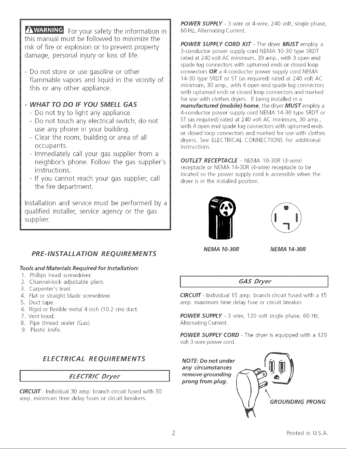
OUTLET RECEPTACLE _ NEMA 10-30R (3-wire)
receptacle or NEMA 14-30R (4-wire) receptacle to be
located so the power supply cord is accessible when the
dryer is in the installed position.
installation and service must be performed by a
qualified installer, service agency or the gas
supplier.
PRE-INSTALLATION REQUIREMENTS
Tools and Materials Required for Installation:
1. Phillips head screwdriver.
2. Channelqock adjustable pliers.
3. Carpenter's level.
4. Flat or straight blade screwdriver.
5. Duct tape.
6. Rigid or flexible metal 4 inch (10.2 cm) duct.
7. Vent hood.
8. Pipe thread sealer (Gas).
9. Plastic knife.
ELECTRICAL REQUIREMENTS
i ELECFR/C Dryer
NEMA 10-30R NEMA 14-30R
GAS Dryer
CIRCUtT- Individual 15 amp. branch circuit fused with a 15
amp. maximum time delay fuse or circuit breaker.
POWER SUPPLY - 3 wire, 120 volt single phase, 60 Hz,
Alternating Current.
POWER SUPPLY CORD _The dryer is equipped with a 120
volt 3-wire power cord.
NOTE: Do not under
any circumstances
remove grounding
1
prong from plug.
CIRCUIT- Individual 30 amp. branch circuit fused with 30
amp. minimum time delay fuses or circuit breakers.
GROUNDING PRONG
2 Printed in U.S.A.
Page 3
EXHAUST SYSTEM REQUIREMENTS
Use only 4 inch (! 0.2 cm) diameter (minimum) rigid or
flexible metal duct and approved vent hood which has a
swing-out damper(s) that open when the dryer is in
operation. When the dryer stops, the dampers automatically
close to prevent drafts and the entrance of insects and
rodents. To avoid restricting the outlet, maintain a minimum
of 12 inches (30.5 cm) clearance between the vent hood
and the ground or any other obstruction.
The following are specific requirements
for proper and safe operation of your dryer. Failure to
follow these instructions can create excessive drying
times and fire hazards.
Number
of
90°
Turns
o
1
2
3
4
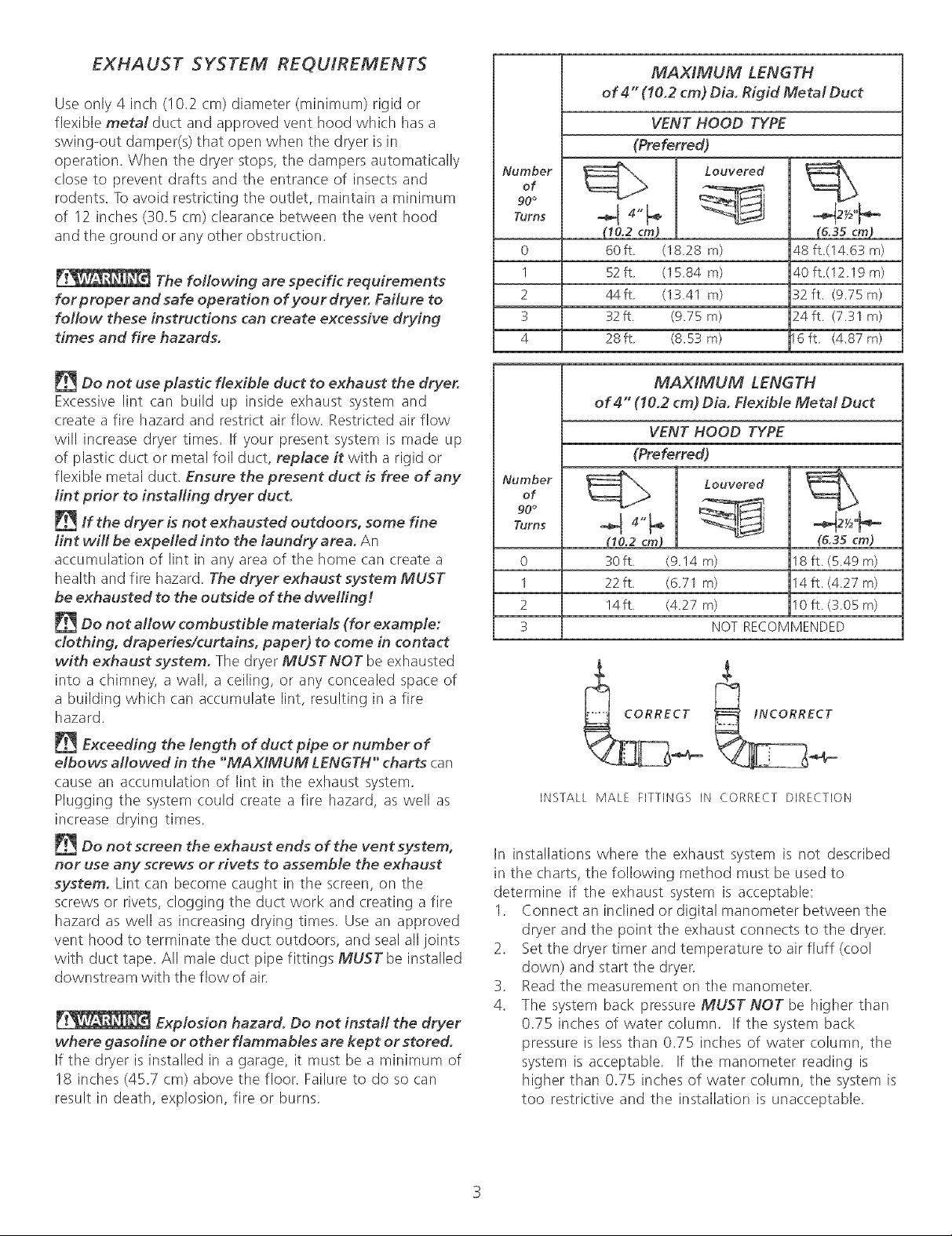
MAX/MUM LENGTH
of 4" (10.2 cm) Dia. Rigid Metal Duct
VENT HOOD TYPE
(Preferred)
Louvered
(10.2 cm)
6Oft (1828 m)
52 ft (1584 m)
44ft (1341 m)
32ft. (9.75 m)
28ft (8,53 m)
(&35 cm)
48 ft (14 63 m)
40 ft (1219 m)
32 ft. (9.75 m)
24ft. (7.31 m)
16ft (4,87m)
Do not use plastic flexible duct to exhaust the dryer.
Excessive lint can build up inside exhaust system and
create a fire hazard and restrict air flow. Restricted air flow
will increase dryer times. If your present system is made up
of plastic duct or metal foil duct, replace it with a rigid or
flexible metal duct. Ensure the present duct is free of any
lint prior to installing dryer duct.
If the dryer is not exhausted outdoors, some fine
lint will be expelled into the laundry area. An
accumulation of lint in any area of the home (:an create a
health and fire hazard. The dryer exhaust system MUST
be exhausted to the outside of the dwelling r.
Do not allow combustible materials (for example:
clothing, draperies/curtains, paper) to come in contact
with exhaust system. The dryer MUST NOT be exhausted
into a chimney, a wall, a ceiling, or any concealed space of
a building which can accumulate lint, resulting in a fire
hazard.
Exceeding the length of duct pipe or number of
elbows allowed in the "MAXIMUM LENGTH" charts can
cause an accumulation of lint in tile exhaust system.
Plugging the system could create a fire hazard, as well as
increase drying times.
Do not screen the exhaust ends of the vent system,
nor use any screws or rivets to assemble the exhaust
system. Lint can become caught in the screen, on the
screws or rivets, clogging the duct work and creating a fire
hazard as well as increasing drying times. Use an approved
vent hood to terminate the duct outdoors, and seal all joints
with duct tape. All male duct pipe fittings MUST be installed
downstream with the flow of air.
Explosion hazard. Do not install the dryer
where gasoline or other flammables are kept or stored.
If the dryer is installed in a garage, it must be a minimum of
18 inches (45.7 cm) above the floor. Failure to do so can
result in death, explosion, fire or burns.
MAX/MUM LENGTH
of 4" (10.2 cm) Dia. Flexible Metal Duct
VENT HOOD TYPE
(Preferred)
Number
of
90 °
Turns
o
1
2
3
_ Louvered
(10.2 cm)
3Oft (914 m)
22ft (671 m)
14ft (427 m)
NOT RECOMMENDED
_CORREC_ L _i
INSTALL MALE FITTINGS IN CORRECT DIRECTION
(6.35 cm)
18 ft (549 m)
14 ft (427 m)
10 ft (305 m)
In installations where the exhaust system is not described
in the charts, the following method must be used to
determine if the exhaust system is acceptable:
1. Connect an inclined or digital manometer between the
dryer and the point the exhaust connects to the dryer.
2. Set tile dryer timer and temperature to air fluff (cool
down) and start tile dryer.
3. Read the measurement on tile manometer.
4. The system back pressure MUST NOT be higher than
0.75 inches of water column. If the system back
pressure is less than 0.75 inches of water column, the
system is acceptable. If the manometer reading is
higher than 0.75 inches of water column, tile system is
too restrictive and tile installation is unacceptable.
Page 4
Althoughverticalorientationoftheexhaustsystemis
acceptable,certainextenuatingcircumstancescouldaffect
theperformanceofthedryer:
Onlytherigidmetalductworkshouldbeused.
Ventingverticalthrougharoofmayexposetheexhaust
systemto downdraftscausinganincreaseinvent
restriction.
Runningtheexhaustsystemthroughanuninsulated
areamaycausecondensationandfasteraccumulation
oflint.
Compression or crimping of the exhaust system will
cause an increase in vent restriction.
The exhaust system should be inspected and (:leaned a
minimum of every 18months with normal usage. The more
the dryer is used, the more often you should check the
exhaust system and vent hood for proper operation.
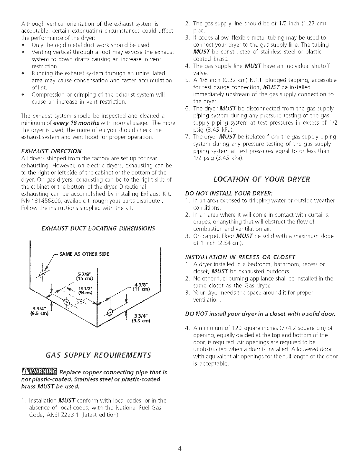
EXHAUST DIRECTION
All dryers shipped from the factory are set up for rear
exhausting. However, on electric dryers, exhausting (:an be
to the right or left side of the cabinet or the bottom of the
dryer. On gas dryers, exhausting carl be to the right side of
the cabinet or the bottom of the dryer. Directional
exhausting carl be accomplished by installing Exhaust Kit,
P/N 131456800, available through your parts distributor.
Follow the instructions supplied with the kit.
EXHAUST DUCT LOCATING DIMENSIONS
2. Tile gas supply line should be of 1/2 inch (127 cm)
pipe.
3. If codes allow, flexible metal tubing may be used to
connect your dryer to the gas supply line. The tubing
MUST be constructed of stainless steel or plastic-
coated brass.
4. Tile gas supply line MUST have an individual shutoff
valve.
5. A I/8 inch (0.32 cm) N.RT. plugged tapping, accessible
for test gauge conne(tion, MUST be installed
immediately upstream of the gas supply connection to
the dryer.
6. The dryer MUST be disconnected from tile gas supply
piping system during any pressure testing of tile gas
supply piping system at test pressures in excess of 1/2
psig (3.45 kPa).
7. Tile dryer MUST be isolated from the gas supply piping
system during any pressure testing of the gas supply
piping system at test pressures equal to or less than
1/2 psig (3.45 kPa).
LOCATION OF YOUR DRYER
DO NOT INSTALL YOUR DRYER:
1. In an area exposed to dripping water or outside weather
conditions.
2. In an area where it will come in contact with curtains,
drapes, or anything that will obstruct tile flow of
combustion and ventilation air.
3. On carpet. Floor MUST be solid with a maximum slope
of 1 inch (2.54 cm).
GAS SUPPLY REQUIREMENTS
Replace copper connecting pipe that is
not plastic-coated. StaiMess steet or plastic-coated
brass MUST be used.
1. Installation MUST conform with local codes, or in the
absence of local (:odes, with the National Fuel Gas
Code, ANSI Z223.1 (latest edition).
INSTALLATION IN RECESS OR CLOSET
1. A dryer installed in a bedroom, bathroom, recess or
closet, MUST be exhausted outdoors.
2. No other fuel burning appliance shall be installed in the
same closet as the Gas dryer.
3. Your dryer needs tile space around it for proper
ventilation.
DO NOT install your dryer in a closet with a solid door.
4. A minimum of 120 square inches (774.2 square cm) of
opening, equally divided at the top and bottom of the
door, is required. Air openings are required to be
unobstructed when a door is installed. A Iouvered door
with equivalent air openings for tile full length of the door
is acceptable.
4
Page 5
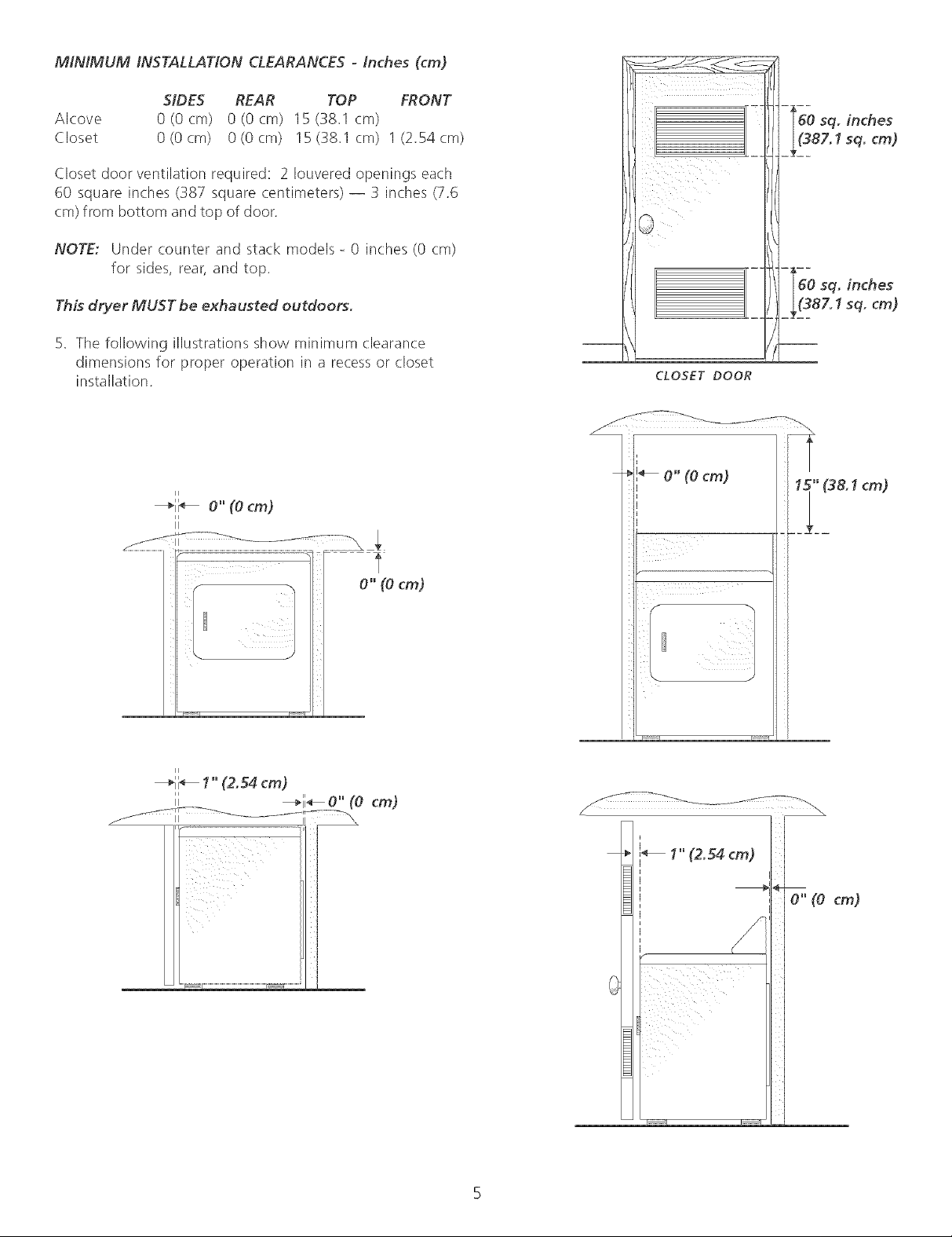
MINIMUM INSTALLATION CLEARANCES - Inches (cm)
SIDES REAR TOP FRONT
Alcove 0 (0 cm) 0 (0 cm) 15 (38.1 cm)
Closet 0(0cm) 0(0cm) 15(38.1 cm) 1(2.54cm)
Closet door ventilation required: 2 Iouvered openings each
60 square inches (387 square centimeters) -- 3 inches (7.6
cm) from bottom and top of door.
NOTE: Under counter and stack models - 0 inches (0 cm)
for sides, rear, and top.
This dryer MUST be exhausted outdoors.
5. The following illustrations show minimum clearance
dimensions for proper operation in a recess or closet
installation.
CLOSET DOOR
ii
_i i_ 0" (0 cm)
ii
i_ I" (2.54 cm)
,, _ii_0" (0 cm)
_ O" (Ocm) I 15"(38.1cm)
J,
I" (2.54 cm)
I
0"(0 cm)
Page 6
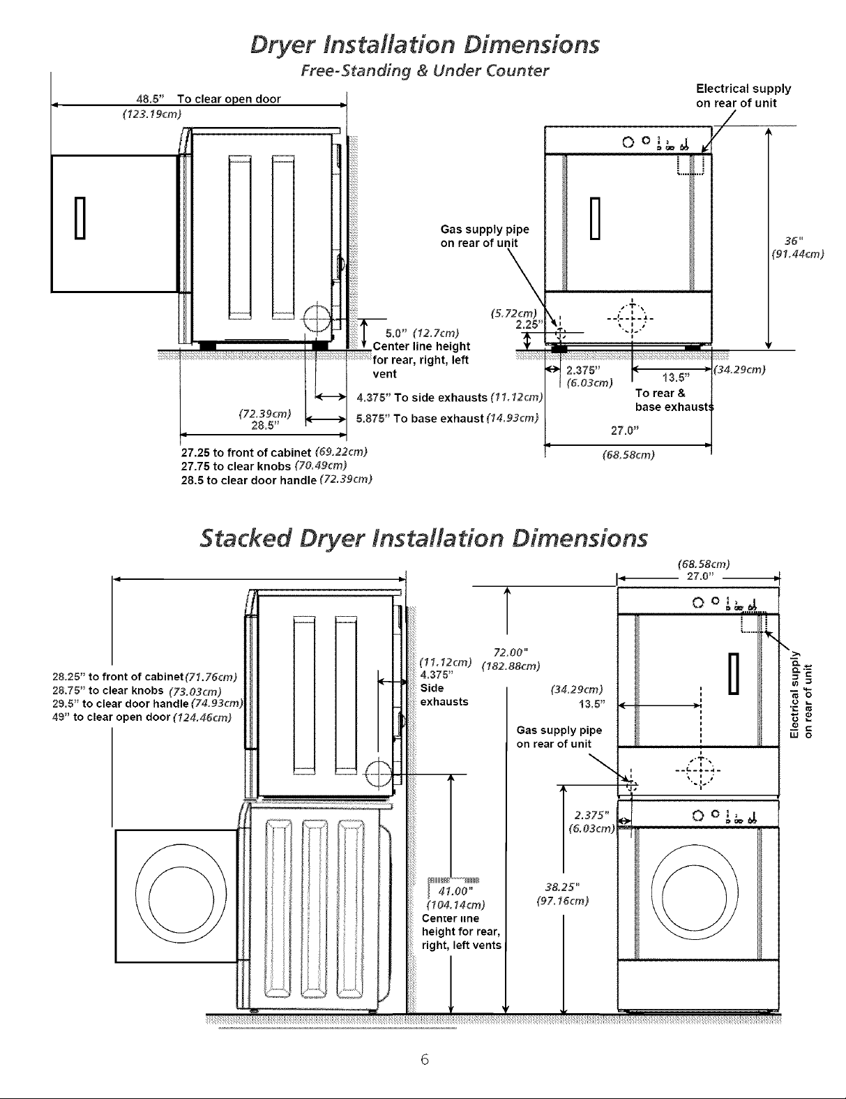
48.5" To clear open door
(123.19cm)
Dryer tnstM/ation Dimensions
Free-Standin 9 & Under Counter
Electrical supply
on rear of unit
/
0 o L_,#, _'
i
D
I--
D
\"
_2.375"
1(&O3cm)
I
i
I.,T-.
i i -
--- °1.-.L-
To rear &
base exhaus
27.0"
(68. 58cm)
13.5"
36 _
'91.44cm)
(34.29cm)
(72.39cm)
28.5"
27.25 to front of cabinet (S&22cm)
27.75 to clear knobs (7&dgcm)
28.5 to clear door handle (72.39cm)
Gas supply pipe
on rear of unit
\
(5.72cm)
5.0" (12.7cm)
Center line height
•, right, left
vent
4.375" To side exhausts (11.12cm)
5.875" To base exhaust (14.93cm)
2.25"
Stacked Dryer Installation Dimensions
(68. 58cm)
ii
27.0" -_
T
28.25" to front of cabinet(71.75cm)
28.75" to clear knobs (73.03cm)
29.5" to clear door handle
49" to clear open door (124.45cm)
72.00"
(11.12cm) (182.88cm)
4.375"
Side
exhausts
41.00"
(104.14cm)
Cenier line
height for rear,
right, left vents
13.5" .
Gas supply pipe
on rear of unit
(&O3cm)
_' 2.375"
38.25"
(97.15cm)
i
i
i
i
i
i
i
i
i
q
!
I"t-_
4- 4
-- - - -
w o
Page 7
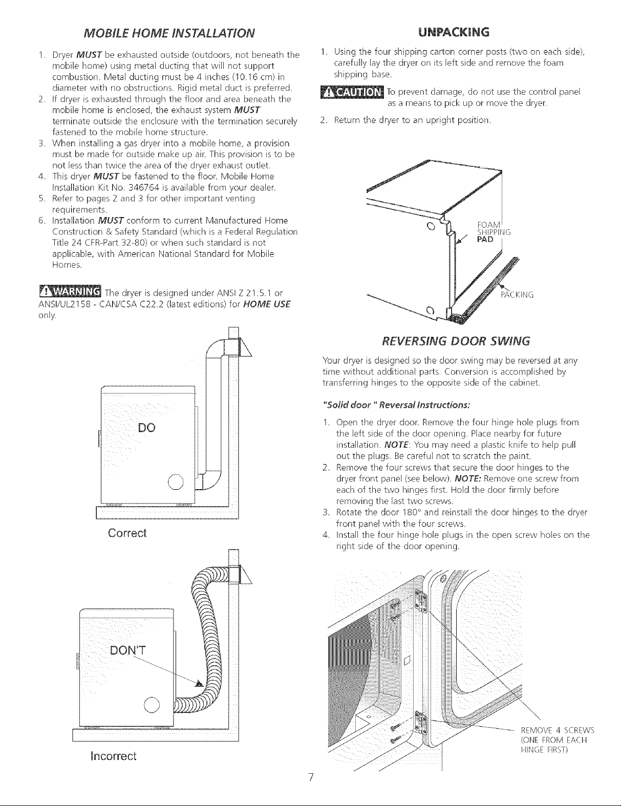
MOBILE HOME INSTALLATION
1 Dryer MUST be exhausted outside (outdoors, not beneath the
mobile home) using metal ducting that will not support
combustion Metal ducting must be 4 inches (1016 cm) in
diameter with no obstructions Rigid metal duct is preferred
2 If dryer is exhausted through the floor and area beneath the
mobile home is enclosed, the exhaust system MUST
terminate outside the enclosure with the termination securely
fastened to the mobile home structure
3 When installing a gas dryer into a mobile home, a provision
must be made for outside make up air This provision is to be
not lessthan twice the area of the dryer exhaust outlet
4 This dryer MUST be fastened to the floon Mobile Home
Installation Kit No 346764 is available from your dealer
5 Refer to pages 2 and 3 for other important venting
requirements,
6 Installation MUST conform to current Manufactured Home
Construction & Safety Standard (which is a Federal Regulation
Title 24 CFR-Part 32-80) or when such standard is not
applicable, with American National Standard for Mobile
Homes,
The dryer is designed under ANSI Z 21_E1 or
ANSVUL2158 - CAN/CSA C222 (latest editions) for HOME USE
only_
1 Using the four shipping carton corner posts (two on each side),
carefully Jaythe dryer on its left side and remove the foam
shipping base
To prevent damage, do not use the control panel
as a means to pick up or move the dryer
2 Return the dryer to an upright position
FOAM
SHIPPING
REVERSING DOOR SWING
Correct
DON'T
Your dryer is designed so the door swing may be reversed at any
time without additional parts_ Conversion is accomplished by
transferring hinges to the opposite side of the cabinet
"Solid door "Reversal Instructions:
1 Open the dryer door Remove the four hinge hole plugs from
the left side of the door opening_ Place nearby for future
installation NOTE; You may need a plastic knife to help pull
out the plugs Be careful not to scratch the paint.
2 Remove the four screws that secure the door hinges to the
dryer front panel (see below) NOTEr Remove one screw from
each of the two hinges first Hold the door firmly before
removing the last two screws_
3 Rotate the door 180° and reinstall the door hinges to the dryer
front panel with the four screws
4 Install the four hinge hole plugs in the open screw holes on the
right side of the door opening
Incorrect
©
\
REMOVE4 SCREWS
(ONEFROMEACH
HINGEFIRST}
Page 8

"Window Door" Reversal Instructions:
1. Open the dryer door. Rernove tile four hinge hole phJgs
from tile left side of the door opening. Place nearby for
future installation NOTE: You may need a plastic knife
to help pull out the plugs Be careful not to scratch the
paint.
2 Remove the four screws that secure the door hinges to
the dryer front panel. NOTE; Remove one screw from
each of the two hinges first. Hold the door firmly before
removing the last two screws.
3 Rernove door handle hole plugs NOTE: Wt_umay need a
plastic knife to help pull out the plugs Be careful not to
scratch the paint
4 Rernove the door handle screws
5 Pull door handle straight ahead to remove
6 Rotate the lens 180 degrees.
7 Remove die transition plugs by sticking a small screw-
driver through the holes vacated by the door handle
plugs.
8 Rotate the lens 180 degrees.
g Place the transition plugs into the holes vacated by the
door handle.
10. Rotate the lens 180 degrees
11. Place the door handle through the lens and reattach
using the screws removed in step 5.
12. Insert the door handle hole plugs in the holes vacated
by die screws removed in step 5
13 Remove the four screws that secure the door hinges to
the door.
14. Remove tile 4 tieqrl screws from the side of tile doon
1S. Using the 4 screws removed in step 4, reinstall the
hinges to the door
16. Reinstall the 4 tie-in screws in the holes vacated by the
door hinge screws removed in step 4.
17. Using the 4 screws removed in step 2, reinstall die door
hinges in the screw holes on the right side of the door
opening.
18. Install the four hinge hole plugs removed in step 1 in the
open screw holes on the right side of the door opening.
2. Remove
screws
7. Remova
of
Transition_
Plugs
I Initial State I
4. Remove 3. Remove
Handle Screws Plastic Plugs
x2
5. Pull Handle
Straight Ahead to
Remove From Door
Steps 6, 8, 10
After 180° Rotation i
9. Add
Transition
Plugs
11.
Replacement
of Handle
! 2. Add Door
11. Add Handle
Screws
!3. Remove
Hinges
Step I 5.
Add Hinges
14. Remove Tieqn Screws
8
Page 9

ELECTRICAL INSTALLATION
j ELECTR/C Dryer 1
The following are specific requirements
for proper and safe electrical installation of your dryer.
Failure to follow these instructions can create electrical
shock and/or a fire hazard.
This appfiance MUST be properly grounded.
Electrical shock can result if the dryer is not properly
grounded. Follow the instructions in this manual for proper
grounding.
2. If your dryer isequipped with a power supply cord having
an equipment-grounding conductor and a grounding plug,
the plug MUST be plugged into an appropriate, copper
wired receptacle that is properly installed and grounded
in accordance with all local codes and ordinances. If in
doubt, call a licensed electrician.
For a permanently connected dryer:
1. The dryer MUST be connected to a grounded metal,
permanent wiring system; or an equipment grounding
conductor must be run with the circuit conductors and
connected to tile equipment-grounding terminal or lead
on the appliance.
_!_ Do not use an extension cord with this dryer. Some
extension cords are not designed to withstand the amounts
of electrical current this dryer utilizes and can melt, creating
electrical shock and/or fire hazard. Locate tile dryer within
reach of the receptacle for tile length power cord to be
purchased, allowing some slack in the cord. Refer to the
preqnstallation requirements in this manual for the proper
power cord to be purchased.
A U.L. approved strain relief must be installed onto
powercord. If the strain relief is not attached, the cord can
be pulled out of the dryer and can be cut by any movement
of the cord, resulting in electrical shock.
Do not use an aluminum wired receptacle with a
copper wired power cord and plug (or vice versa). A
chemical reaction occurs between copper and aluminum
and can cause electrical shorts. The proper wiring and
receptacle is a copper wired power cord with a copper
wired receptacle.
NOTE: Dryers operating on 208 volt power supply will have
longer drying times than operating on 240 volt power supply.
GAS Dryer j
This dryer is equipped with a three-prong (grounding) plug
for your protection against shock hazard and should be
plugged directly into a properly grounded three-prong
receptacle. Do not cut or remove the grounding prong from
this plug.
GROUNDING REQUIREMENTS
J ELECTR/C Dryer 1
Improper connection of the equipment
grounding conductor can result in a risk of electrical shock.
Check with a licensed electrician if you are in doubt asto
whether the appliance isproperly grounded.
For a grounded, cord-connected dryer:
1. Tile dryer MUSTbe grounded. In the event of a
malfunction or breakdown, grounding will reduce the risk
of electrical shock by a path of least resistance for
electrical current.
Page 10

GREEN GREEN POWER CORD
ELECTRICAL CONNECTIONS
FOR 4-WIRE SYSTEM
ELECTRICAL CONNECTIONS
FOR 3-WIRE SYSTEM
[ ELECTR/C Dryer i
1. Remove the screws securing the terminal block access
cover and the strain relief mounting bracket located on
the back of the dryer upper corner.
2. Install a U.L approved strain relief into the power cord
entry hole of the mounting bracket. Finger tighten the nut
only at this time.
3. Thread a U.L approved 30 amp. power cord, NEMA
10-30 type SRDT,through the strain relief.
4. Attach the power cord neutral (center wire) conductor to
the silver colored center terminal on tile terminal block.
Tighten the screw securely.
5. Attach the remaining two power cord outer conductors to
the outer brass colored terminals on tile terminal block.
Tighten both screws securely.
Do not make a sharp bend or crimp wiring/
conductor at connections.
6. Reattach the strain relief mounting bracket to the back of
the dryer with two screws. Tighten screws securely.
7. Tighten the screws securing the cord restraint firmly
against the power cord.
8. Tighten the strain relief nut securely so that the strain
relief does not turn.
9. Reinstall the terminal block cover.
i
1.
Remove the screws securing the terminal block access
cover and tile strain relief mounting bracket located on
the back of the dryer upper corner.
.
Install a U.L approved strain relief in the entry hole of
the mounting bracket. Finger tighten the nut only at this
time.
.
Remove the ground wire from the green ground screw
located above tile terminal block.
4. Thread a U.L approved 30 amp power cord, NEMA 14-30
type ST or SRDT through the strain relief.
5. Attach the green power cord ground wire to the cabinet
with the green ground screw.
6. Attach the white (neutral) power cord conductor from the
power cord and the ground wire from the dryer harness to
the silver-colored (:enter terminal on the terminal block.
Tighten the screw securely.
7. Attach the red and black power cord conductors to the
outer brass-colored terminals on the terminal block.
conductor at the connections.
8. Tighten the screws securing the cord restraint firmly
against the power cord.
9. Tighten the strain relief nut securely so the strain relief
does not turn.
10. Reinstall the terminal block access cover.
10
EL ECTR/C Dryer
TYPICAL 4
CONDUCTOR BLACK 240V
30 AMP NEMA 14-30 TYPE SRDT OR ST
Do not make a sharp bend or crimp wiring/
Page 11

GAS CONNECTION
1. Remove the shipping cap from gas pipe at the rear of
the dryer.
NOTE; DO NOT connect the dryer to L.R gas service
without converting the gas valve. An LR
conversion kit must be installed by a qualified gas
technician.
Connecta /2 inch (1,27cm) I.D. semi-rigid or approved
pipe from gas supply line to the 3/8 inch (0,96 cm) pipe
located on tile back of tile dryer (see pages 6 and 7),
Use a 1/2 inch to 3/8 inch (!,27 cm to 0.96 cm) reducer
for a connection. Apply an approved thread sealer that
is resistant to the corrosive action of liquefied gases on
all pipe connections.
3. Open tile shutoff valve in the gas supply line to allow
gasto flow through pipe.
VALVE OPEN / GAS FLOW POSITtON
5. Run the dryer through a cycle check for proper
operation.
NOTE: On gas dryers, before the burner will light, it is
necessary for the gas line to be bled of air. If the
burner does not light within 45 seconds the first
time the dryer is turned on, the safety switch will
shut the burner oft. If this happens, turn the timer
to "OFF" and wait 5 minutes before making another
attempt to light.
6. If your dryer does not operate, please review the "'Avoid
Service Checklist"' located in your Use and Care Guide
before calling for service.
7. Placethese instructions in a location near the dryer for
future reference.
NOTE: A wiring diagram is located inside the dryer
console or under the top panel.
REPLA CEMENT PARTS
.
Test all connections by brushing on a soapy water
solution. NEVER test for gas leaks with an open
flame.
GENERAL INSTALLATION
1. Connect the exhaust duct to outside exhaust system
(see pages 3 and 4), Use duct tape to seal all joints.
2. With the dryer in its final position, adjust one or more of
the legs until the dryer is resting solid on all four legs.
Placea level on top of the dryer. The dryer MUSTbe
level and resting solid on all four legs.
3. Plug the power cord into a grounded outlet. NOTE:
Check to ensure the power is off at circuit breaker/fuse
box before plugging the power cord into tile outlet.
4. Turn on the power at the circuit breaker/fuse box.
Before operating the dryer, make sure the
dryer area is clear and free from combustible materials,
gasoline, and other flammable vapors. Also see that
nothing (such as boxes, clothing, etc.) obstructs the
flow of combustion and ventilation air.
If replacement parts are needed for your dryer, call
Sears Parts and Service Toll Free Number
1-800-355-PART(1-800-366-7278).
Label all wires prior to disconnection when
servicing controls. Wiring errors can cause improper and
dangerous operation. Verify proper operation after servicing.
Destroy tile carton and plastic bags after
the dryer is unpacked. Children might use them for play.
Cartons covered with rugs, bedspreads, or plastic sheets
can become airtight chambers causing suffocation. Place
all materials in a garbage container or make materials
inaccessible to children.
The instructions in this manual and all other
literature included with this dryer are not meant to cover
every possible condition and situation that may occur.
Good safe practice and caution MUST be applied when
installing, operating and maintaining any appliance.
11
Page 12

Requerimientos de instalacion preliminares ....... 2
Requerimientos electricos ............................... 2
Requerimientos del sistema de escape............ 3-4
Requerimientos del suministro de gas............... 4
Ubicacion de su secadora............................... 4-5
Dimensiones para la instalacion ...................... 6
Instalacion en casasmoviles ........................... 7
Desembalaje .................................................. 7
Puerta reversible ............................................ 7-8
Instalacion electrica ........................................ 9
Requerimientos para la puesta a tierra ............... 9
Conexiones electricas - trifilares ....................... I 0
Conexiones electricas - tetrafilares ................... 10
Conexion del gas............................................ 11
General Instalacion ......................................... 11
Secadora a gas y el6ctrica
Piezas de recambio ........................................ 11
Antes de comenzar la instMacion, tea cuidadosamente estas instrucciones. Esto simplih'carb ta instalacidn y
asegurarb que la secadora se instMe correctamente y de manera segura. Despu@s de completar la instMaci6n,
coloque estas instrucciones cerca de la secadora para referencia futura.
NOTA: Laalimentacion ele(trica para la secadora deber_ cumplir (:onlos c6digos y reglamentos localesy (:onla Oltima
edition del COdigo Electrico National, ANS!/NFPA70.
NOTA: Laalimentacion de gaspara la secadora deber_ cumplir con loscodigos y reglamentos locales y con la Oltima
edition del C6digo National para GasesCombustibles, ANS! Z223.1.
NOTA: Lasecadora est_ dasificada para US0 DOMESTICO solamente, de acuerdo con la norma ANS! Z2! .5.1 o ANS!/
UL2158 - CAN/CSA C22.2 (las Oltimasediciones). Estasecadora no serecomienda para uso commercial tal como en
restaurantes, salones de belleza, etc.
Conserve estas instrucdones
Sears, Roebuck and Co., Hoffman Estates, IL 60179 U.S.A.
P/N 134472500 (0409)
Page 13

Para su seguridad, siga Ias
instrucciones contenidas en este manual a fin
de reducir a un minimo los riesgos de incendio o
explosion o para evitar danos materiales,
lesiones personales o la muerte.
No almacene ni utilice gasotina u otros
vapores y Ifquidos inftamables en la
proximidad de 6ste o de cualquier otro
artefacto elOctrico.
QUE DEBE HACER SI PERCIBE OLOR A GAS
. No trate de encender ning0n artefacto
et_ctrico.
. No toque ning0n interruptor etOctdco; no use
ning0n teI_fono en su edificio.
. Haga salir a todos los ocupantes de la
habitaci6n, deI edificio y deI Iugar.
. Ltame a su proveedor de gas desde el
tebfono de un vecino. Siga Ias
instrucciones det proveedor de gas.
. Si no Iogra comunicarse con su proveedor
de gas, Ilame al departamento de
bomberos.
ALIMENTACtON ELECTRICA - Corriente alterna, monof_Ssica, 60
Hz, 240 voltios; trifilar o tetrafilar
CORDON ELECTRICO - En la secadora se DEBE usar un cordon
elOctrico trifilar NEMA 10o30 tipo SRDT para un voltaje nominal
mfnimo de 240 voltios CA, 30 amp., con 3 conectores de
horquillas con terminales abiertos y extremos dirigidos hacia
arriba o conectores de anillo cerrado y marcados para uso en
secadoras de ropa o_ un cordon elOctrico tetrafilar NEMA 14-30
tipo SRDT o ST (como sea necesario) para un voltaje nominal
m[nimo de 240 voltios CA, 30 amp. con 4 conectores de horquillas
con terminales abiertos y extremos dirigidos hacia arriba o
conectoresdeanillocerrado. SilainstalaciOnserealizaenuna
casa mOviJ, se DEBE utilizar un cordon elOctrico tetrafilar NEMA
14-30 tipo SRDT o ST (como sea necesario) para un voltaje
nominal m[nimo de 240 voltios CA, 30 amp. con 4 conectores de
horquillas con terminales abiertos y extremos dirigidos hacia
arriba o conectores de anillo cerrado y marcados para uso en
secadorasde ropa Ver CONEXIONES ELECTRICAS para
adicional informaciOn
TOMACORRIENTE ° El tomacorriente NEMA 10o30R (3
alambres) o NEMA 14°30R (4 alambres) debe estar ubicado de
manera que el cordon elOctrico Ilegue hasta el cuando la
secadora este instalada.
La instalaciOn y el serviclo de mantenimiento
debe de realizarlos un instalador calificado, la
agencia de servicios o el proveedor de gas.
REQUERIMIENTOS DE INSTALACION PREM-
MINARES
Herramientas y materiales necesarios para la instalaciOn:
1. DestorniHador Phillips
2. AJicates universales
3. Nivel de carpintero
4. DestorniHador para torniHo de cabeza pJana o recta
5. Cinta para ductos
6 Ducto met_ilico figido o flexible de 4"(10,2 cm)
7. Caperuza de salida
8. SeHador de tuberfas (gas)
9. Un cuchillo de pkistico
REQUERIMIENTOS ELECTRICOS
Secadoras ELECTR/CAS
NEMA IO-30R NEMA 14-30R
I Secadofas a GAS
CIRCUITO - Circuito individual derivado de 15 amp, con fusibles
de 15 amp. de retardo m_iximo o disyuntor
ALtMENTACION ELECTRICA - Corriente alterna, monof_isica,
60 Hz, 120 voltios, trifilar
CORDON ELECTRICO - La secadora est_ equipada con un
cordon elOctrico trifilar para 120 voltios
NOTA: No saque pot
ningbn motivo Ja
espiga de puesta a
tierra del enchufe,
1
1
CIRCUtTO - Circuito derivado individual de 30 amperios, con
fusibles de 30 amp, del tipo de retardo minimo o disyuntores
Impreso en los EE,UU,
2
Page 14

REQUERIMIENTOS DEL SISTEMA DE ESCAPE
Uti[ice so[amente ductos metalicos, r[gidos o flexib[es de 4"
(10,2 cm) de di_imetro (mfnimo) y una caperuza de sa[ida de uso
aprobado, con registros que giren hada afuera que se abren
cuando [a secadora se encuentra en fundonamiento, Cuando [a
secadora se detiene, los registros se derran autom_iticamente
para evitar [as corrientes de aire y [a entrada de insectos y
roedores, Para evitar obstruir [a sahda, mantenga una a[tura [ibre
mfnima de 12"(30,5 cm) entre [a caperuza de sa[ida y el piso o
entre cualquier otra obstrucci6n_
especificos para el funcionamiento correcto y seguro de su
secadora. El incumplimiento de estas instrucciones puede
causar prolongaci6n excesiva del tiempo de secado y riesgos
de incendio.
LARGO MAXIMO
del Conducto Metblico Rigido
de 4" (10,2 cm) de Dibmetro
TIPO DE CAPERUZA DE SALIDA
(Preferido)
ogoo ,"F
(10,2 cm_ (6.35 cm_
0 60 pies (18,28 m) 48 pies(!4,63 m)
1 52 pies (15,84 m) 40 pies(12,19 m)
2 44 pies (13,41 m) 32 pies (9,75 m)
3 32 pies (9,75 m) 24 pies (7,31 m)
4 28 pies (8,53 m) 16 pies (4,87 m)
_ No use ductos flexibtes de pl_stico para el escape de la
secadora,
Se puede acumular un exceso de pelusas en el sistema de
escape, crear un riesgo y obstruir el flujo de aire_ La restricci6n
del flujo del aire prolongar_i el tiempo de secado_ Si su sistema
de escape actual tiene ductos de pl_istico o de I&minas met_ilicas
delgadas, reemplacelo con un ducto meta'lico r[gido o flexible
Asegurese de que los ductos existen tes no tengan pelusas an tes
de instMar el ducto de la secadora.
_ Si el escape de la secadora no se dirige al exterior, algunas
pelusas finas seran sopladas hacia el recinto donde se efect_a el
lavado. La acumulaci6n de pelusas en cualquier lugar de la casa,
puede crear un peligro para la salud y un riesgo de incendio, iEf
sistema de escape de la secadora DEBE estar dirigido hacia el
exterior de la vivienda t
_ No permita que los materiMes combustibles (pot ejemplo:
la ropa, cortinas!cortinajes, papel) tengan contacto con los
ductos. E[escape de [a secadora NO DEBE dirigirse hacia el
interior de una chimenea, hacia una pared, hacia e[ cielo raso o
hacia cua[quier otro espacio reducido del edificio, donde puede
ocurrir acumulaci6n de pe[usas y constituir un pe[igro de
incendio
_ Ex ceder la Iongitud del conducto rigido o los n_meros de
codos permitidos en los diagramas "LARGO MAXIMO" puede
disminuirlacapacidaddeexhaustaci6ndelsistema_ Obstruirel
conducto puede provocar peligro de incendio, asf como
aumentar el tiempo de secado_
ONo coloque un filtro en el extremo del escape del sistema ni
emplee tornillos o remaches para ensamblar elsistema de
escape. Las pelusas podfian quedar atrapadas en los filtros, en
los tornillos o en los remaches, Io cual obstruifia el sistema de
escape ycrear[aunriesgodeincendio, asfcomotambi6n
prolongarfaeltiernpodesecado Useunacaperuzadesalida
adecuada para el extremo del ducto que salga al exterior de la
vivienda y selle todas las juntas con cinta adhesiva para ductos.
Todos los accesorios de tuber[a machos, DEBEN ser instalados
aguas abajo del flujo de aire.
Riesgo de explosi6n_ No instale la
secadora donde se guarda gasolina u otros materiales
inflamables. Si la secadora se instala en un garage, ella debe
estar por Io menos 18 pulgadas (45,7 cm) por encima del suelo
El incumplimiento puede resu[tar en [a muerte, exp[osi6n,
incendio, o quemaduras
LARGO Mt_XIMO
def Conducto Metbtico Flexible
de 4" (10,2 cm) de D#metro
TJPO DE CAPERUZA DE SALIDA
(Preferido)
(10,2 cm_ (6.35 cm)
0 30 pies (9,14m) 18 pies (5,49 m)
1 22 pies (6,71 m) 144 pies (4,27 m)
2 14 pies (4,27 m) 10 pies(3,05 m)
3 NO RECOMENDADO
CORRECTO
[NSTALE LOS ACCESORIOS MACHOS EN LA DIRECCI©N CORRECTA
Para las instalaci6nes cuyas sistema de exhaustaci6n no se encuentre
en el diagrama, se puede utilizar el metodo a continuaci6n para
determinar si e[ sistema de exhaustaci6n es apropiado_
1. Conecte un man6rnetro a tubo inclinado o digital entre la
secadora y el uni6n de exhaustaci6n de la secadora_
2. Ponga el contador de tiempo de la secadora y la temperatura
a aire fifo (enfiriamiento), y la secadora en la posici6n de
marcha,
3, Lea la medida indicada en el man6metro
4, La baja presion NO DEBEexceder 075 pulgada de la
columna deagua_ Si la baja presion esinferior a 075" dela
columna de agua, el sistema es aceptable_ Si la lectura indica
una presion superior a 0_75" de la columna de agua, la
capacidad del circuito es insuficiente y la instalaci6n es
inaceptable
Page 15

Aungueunsisternaverticalseaaceptable,algunascircunstancias
atenuantespuedenafectarelfuncionarnientodelasecadora:
Sedebeutilizarsolamenteconductosmetalicosrigidos.
Unasalidadelsisternaverticaleneltecho,puedeexponerlea
uncorrientedeairedescendenteydisrninuirasisucapacidad
deexhaustaci6n.
Elaislantequedebeatravesarelsisternapuedecausar
condensaci6nydisrninuirasilacapacidaddeexhaustaci6n
delsisterna
Lacapacidaddeexhaustaci6ndeunsisternade
exhaustaci6ncornprirnidooonduladopuededisrninuirse
Elsisternadeexhaustaci6ndebedeserinspeccionadolirnpiado
porIornenoscada 18meses de uso normal. Cuanto rn_Ssla
secadora est,1 utiJizada, rn_is debe verificar el buen funcionarniento
del sisterna de exhaustaci6n y de la tapa deJ orificio de ventiJaci6n.
UBICACION DEL ESCAPE
Todas Jas secadoras vienen de f_ibrica equipadas con escape
trasero. Sin embargo, enlassecadorasel6ctricas, elescape
puede hacerse al lado derecho o izquierdo del gabinete o en la
parteinferiordeJasecadora. EnJassecadorasagas, elescape
deJ aire puede estar en el lado derecho del gabinete o en Ja
parte inferior de la secadora. El escape direccional puede
efectuarse instalando un Juego de Escape, P/N 131456800,
disponibleatrav6sdesu distribuidorderepuestos SigaJas
instrucciones que se surninistran con el juego
2. La tuberia de alirnentaci6n de gas debe ser de 1/2 pulgada
(I ,27 crn) de di_irnetro
3. Si est,1 permitido por los c6digos locales, se puede usar
tuberia de metal para conectar su secadora a la linea de
suministro de gas. La tuberfa DEBE ser fabricada de acero
inoxidable o cobre recubierto de p!_istico.
4. La tuberia de alirnentaci6n de gas DEBEtener una Ilave de cierre
individual
5. Una torna de 1/8 de pulgada (0,32 crn) N.P.T accesible para
conexi6n del rnan6rnetro de prueba, DEBE ser instalada
inrnediatarnente aguas arriba de la conexi6n de la tuberia
de alirnentaci6n de gas a la secadora.
6. La secadora DEBE ser desconectada del sisterna de tuberias
de alirnentaci6n de gas durante cualquier ensayo de presi6n
del sisterna de tuberias de alirnentaci6n de gas realizado a
presiones de prueba de rn_is de 1/2 Ibs/pulg 2(3,45 kPa)
7. La secadora DEBE aislarse del sisterna de tuberias de
alirnentaci6n de gas durante cualquier ensayo de presi6n del
sisterna de tuberias de alirnentaci6n de gas realizado en
ensayos de presi6n iguales o inferiores a 1/2 Ibs/pulg. 2 (3,45
kPa),
UBICACION DE SU SECADORA
NO INSTALE SU SECADORA:
1, En un lugar donde puede haber goteos de agua o quede
expuesta alas inclemencias del tiernpo,
2, En un a'rea donde pueda entrar en contacto con cortinas,
cortinajes o cualquier otra cosa que obstruya el flujo de
cornbusti6n y ventilaci6n de aire,
3, Sobre alfornbras El piso DEBE ser firrne con un desnivel
rn_ixirno de 1 pulgada (2,54 crn)
REQUERIMMENTO$ [}EL SUMINISTllO DE GAS
Reemplace la tuberia de conexi6n de
cobre que no est# recubrida con pl#sticoo El lat6n inoxidabte o
recubrido con pf#stico DEBE 5ER udlizado,
1 La instalaci6n DEBE hacerse cumplir con los c6digos locales o
en ausencia de los rnisrnos, de acuerdo con los estandares
deJ National Fuel Gas Code (C6digo National para Gases
Combustibles), ANSI Z223.1 (Ja QJtirna editi6n)
INS TA LA CIONDENTRO DE UN NICHO 0 A RMA RiO
1. Si la secadora es instalada en un dormitorio, cuarto de bar]o,
nicho o arrnario, el tubo del escape DEBE ser instalado hacia
el exterior
2. No se debe instaJar ningQn otro artefacto que querne
combustible en el rnisrno arrnario en que est_ instalada Ja
secadora a Gas
3. La secadora necesita espacio a su alrededor para una
ventilaci6n adecuada
NO instale la secadora en un armario con puerta maciza,
4. Se requiere corno rninirno una abertura de 120 pulgadas
cuadradas (774,2 crnZ), dividida equitativarnente para la
partesuperioreinferiordeJa puerta CuandoseinstaJa una
puerta, es necesario proveer aberturas para el aire. Una
puerta apersianada con aberturas para el aire en todo el
largo de Ja puerta es aceptable
Page 16

DESPEJES MiNIMOS DE INS TA LA CION - Putgadas (cm)
Parte Parte Parte
Lados Trasera Superior Delantera
Alcoba 0 (0 cm) 0 (0 cm) 15(38,1 cm)
Armario 0(0cm) 0(0cm) 15(38,1cm) 1(2,54cm)
Ventilaci6n requirida en la puerta del armario: dos aberturas
rejilladas cada 60 pulg_2(387 cm2)-- 3" (7,6 cm) desde la parte
inferior y superior de la puetra
NOTA: Secadoras encastradas o superpuestas -- 0 pulgada
(0 cm) para los lados, parte trasera y en la parte
superior
El tubo del escape de la secadora debe ser instalado hacia el
exterior,
5 Las siguientes ilustraci6nes muestran las dimensi6nes
mfnimas de espacio libre que debe existir para el buen
funcionamiento de la secadora cuando se instala en un nicho
o en un arrnario.
nn
-41_--1" e,s4 c_)
a_ On
÷un_ (0cm)
PUERTADELARMARmO
o1" _2o54 era)
/_ .................. i "7
O" (0 _:m)
Page 17

Dimensiones De la InstalacI_n
Fuente e[_ctriea en [a parte
posterior de ta unidad
OOi, .I
l
Pipe de [a fuente de
gas en [a parte
posterior de [a unidad
5.0" (12.7cm) _ _.
L{nea aitura de ¢entro para
el respiradero posterior, _i??
derecho, izquierdo
(ll.12em)
4.375"Para echar a un [ado extractoree
(27.39cm) 5,875"Para baear roe extractoreJ
28.5" (14.93cm)
27.25 AI frente de{ gabinete (69.22cm)
27.75 A [as periHae e[aras (70.49cm)
28,5 A [a manija clara de [a puerta (72.39em}
l
.... I.-.L -
27,0"
(68.58cm)
i
I.'1-,
r" i •
,. _ s
_1 _
A roe extractoree de _a parte
posterior y de la base
Dimensiones Apiladas De la Instalaci6n De1 Secadora
(71.7Gem) q
28.25" A[ frente del gabinete |
28.75" A [as perHiae clarae (73.03cm}
29.5" A la manija c_ara de [a puerta (14.93cm}
49" En ei claro abra [a puerta /
(124.46em
L
T
(11.12cm)
4.375"
Para eehar a un
[ado extraetoree
L[nea a_tura de centro
para el reepiradero
posterior, derecho,
izquierdo
71.75"(182.25em)
I
Pipe de _a fuente de gas
en la parte posterior de
la unidad
(34,2ecru)
13.5"
(6.03¢m}
2.375"
Fuente
ei_ctrica
\en ta
parte
)osterior
de [a
unidad
-- - _'_
Page 18

INSTALA CION EN CASA5 MOWLES
1, El tubo de escape de la secadora DEBE set instalado hacia el
exterior (El escape debe colocarse en la parte exterior y no
debajo de la casa m6vik) Debe usarse ducto de metal que no
sea combustible EIductodemetaldebetenercuatro
pulgadas (10,16 cm) de diametro y no tenet obstrucciones, Es
preferible usar ducto de metal que sea Hgido_
2, Si el tubo de escape de la secadora torte a traves del piso y el
area debajo de la casa m6vil es cerrada, el ducto de escape
DEBE terminar fuera del recinto, con el extremo final
asegurado en contra de la estructura de la casa m6vil
3, AI instalar una secadora de gas en una casa m6vil, hay que
instalar una provisi6n de aire fresco suplementario La
provisi6n tiene que set ma's grande que dos veces el espacio
del escape de la secadora_
4, Esta secadora DEBE asegurarse al piso. El juego para
instalaci6n en la casa m6vil es el No, 346764 y Io puede
adquirir con su distribuidor
5, Vea las p_qginas 2 y 3 para otros requ[sitos importantes de
ventilaci6n
6, La instalaciOn DEBE cumplir con las est_qndares aplicables de la
Manufactured Home Construction & Safety Standard -
Est_Sndares de Seguddad y Construcci6n de Casas
Prefabricadas (Tftulo 24 CFR - Parte 32-80 del Reglamento
Federal) o cuando dichos esta'ndares no sean aplicables, se
deben complir con los estandares de la American National
Standard for Mobile Homes (Est_ndares Nacionales
Americanas para Viviendas M6viles)_
Esta secadora ha sido disenada PARA USO
DOMESTtCO solamente, de acuerdo con la norma ANSI Z 21,5,1 o
ANSI/UL 2158°CAN/CSA C222 (las 01timas edici6nes
Sm
CORRECTO
MODELO5 A UTONOMOS CON CONSOLA
SUPERIOR
DtMENSIONES PARA LA INSTALACI6N
DESEMBALA]E
1, Utilizando las cuatro esquineras de embarque de la caja de cart6n
(dos a cada lado), coloque cuidadosamente la secadora sobre el
costado izquierdo y saque la base de espuma de embarque_
Para evitar darhos, no use el panel de control como
un medio para levantar o mover la secadora
2, Vuelva la secadora a su posici6n vertical,
PLACA DE
ESPUMA DE
,_/ EMBARQUE
MPAQUE
PUERTA REVERSIBLE
Su secadora ha sido diseFiada para que la puerta pueda ser
cambiada de lado en cualquier momento sin necesidad de
piezas adicionaJes_ La conversi6n se hace transfiriendo las
bisagras aJ lado opuesto del gabinete
C6mo cambiar /a direcci6n de apertura de la puerta:
1, Abra[a puerta delasecadora Quite Ioscuatroreceptoresdel
agujero de [a bisagra del [ado izquierdo de la apertura de [a
puerta Co[6que[osenun[ugarcercanoparafutura
insta[aci6n NOTA: Puede que se necesite un cuchil[o de
pla'stico para poder sacar los receptores Tenga cuidado de no
rayar la pintura
2, Quite los cuatro torni[los que aseguranlas bisagras de [a
puerta al panel frontal de la secadora (vet figura abajo)_
NOTA: Primero quite un torni[[o de cada una de [as bisagras
Mantenga [a puerta sujetada firmemente antes de quitar los
dos OItimos tornillos
3 Gire la puerta 180 ° y vuelva a co[ocar las bisagras de la puerta
en el panel frontal con los cuatro tornillos_
4, Insta[e los cuatro receptores de los agujeros de [as bisagras
en los agujeros abiertos en el [ado derecho de [a apertura de
i[[ ¸
INCORRECTO
©
\
QUITE LOS CUA1-RO
TORNILLOS (PRIMERO QUITE
UNO DE CADA BISAGRA)
Page 19

lnstrucdonesDe la Revocadon De la Puerta De la Ventana
1, Abra [a puerta del secador, Quite los cuatro tap6ns del
agujero de la bisagra del lado izquierdo de la abertura de la
puerta, Coloque cerca para la instalaci6n futura. NOTA:
Usted puede necesitar un cuchillo plastico ayudar a sacar
los tap6ns, l_nga cuidado de no rasgut_ar la pintura.
2, Quite los cuatro tornillos ese seguro las bisagras de la puerta
al panel delantero del secador NOTA: Quite un tornillo de
cada uno de las dos bisagras primero. Sostenga la puerta
firmemente antes de quitar los dos tornillos pasados. 3. Quite
los tapons del agujero de la manija de la puerta NOTA:
Usted puede necesitar un cuchillo pBtko ayudar a sacar los
tapons, 1-_ngacuidado de no rasgunar Fapintura.
4, Quite los tornillos de la manija de la puerta
5 Tire de la manija de la puerta todo derecho para quitar, 6,
Rote la lente 180 grados.
7 Quite los tap6ns de B transition pegando un destornillador
peque_o a traves de los agujeros desocupados por los
tap6ns de la manija de la puerta,
8. Rote la lente 180 grados.
9, Coloque los tap6ns de la transition en los agujeros
desocupados pot B manija de B puerta,
10. Rote la lente 180 grados.
1I. Coloque la manija de la puerta a trav#s de la lente y reatela
con los tomillos quitados en el paso 5.
12. Inserte el agujero de la manija de la puerta tap6ns los
agujeros desocupados por los tornillos quitados en el paso 5.
1;3.Quite los cuatro tornillos ese seguro las bisagras de la puerta
a la puerta
14. Quite los 4 tornillos de la relaci6n del lado de la puerta.
15. Con los 4 tornillos quitados en el paso 4, reinstale las bisagras
a la puerta
16. Reinstale los 4 tornillos de la relaci6n en los agujeros
desocupados por los tornillos de la bisagra de la puerta
quitados en el paso 4,
17. Con los 4 tornillos quitados en el paso 2, reinstale las bisagras
de la puerta en los agujeros del tornillo en el derecho de la
abertura de la puerta.
18. Instale los cuatro tap6ns del agujero de la bisagra quitados
en el paso 1 en los agujeros abiertos del tornillo en el
derecho de la abertura de la puerta,
2. Quite Los
Tornillos
7. Retiro de
los Tapdns
de la
Transici6f_,
4. Quite Los
3. Quite Los
Tornillos De la Tap6ns PBsticos
Manija
Pesos 6, 8, 10
9. 12.
Agregue Agregue
Los Los
Tapos Tapds de
la la
Transition Puetra
11. Reemplazo
de la Manija
[ Despuds De 180 ° RotatJn]l Estado Initial ]
11. Agregue
LosTornillos De
la Manija
13. Quite las
Bisagras
15. Agregue lasBisagras
14. Quite el Lazo en Tornillos
8
Page 20

INS TALA OON ELECTRfCA
[ SecadorasELECTR/CAS [
_ !_ Los siguientes requerimien tos son
especificos para el funcionamiento correcto y seguro de su
secadora° El incumplimiento de estas instrucciones p uede
causar prolongaci6n ex cesiva del dempo de secado y riesgos
de incendio,
_ Este artefacto DEBE ser puesto a derra de manera
correcta, Si la secadora no est,1 debidamente puesta a tierra se
puede producir un choque el6ctrico. Siga las instrucciones
indicadas en este manual para la puesta a tierra en forrna
correcta
_ No use un cord6n de extensi6n con esta secadora°
Algunos cordones de extensi6n no pueden soportar la cantidad
de comente el6ctrica que utiJiza esta secadora y pueden
fundirse, creando un peligro de choque el6ctrico y/o incendio.
Ubique la secadora de rnanera que el cord6n eJ6ctrico Ilegue
hasta el tornacorriente que se va a usar, dejando un poco de
hoJgura paraelcord6n Consultelosrequerirnientosde
instalaci6n preJirninares indicados en este manual para el
cord6n el6ctrico que debe ser adquirido.
_ Se debe instalar un anclaje aprobado por el U,L. para el
cord6n electricoo Si no se utiliza un anclaje para sujetar el
cord6n electrico, este puede salirse de la secadora y cortarse
con cualquier rnovirniento, resultando en un choque electrico
_ No utilice un tomacorriente con cables de aluminio con un
cord6n y un enchufe de cobre (o viceversa), 5e produce una
reacci6n qufrnica entre el cobre y el alurninio que puede causar
cortacircuitos. El cableado y tomacorriente apropiado es un
cord6n el_ctrico equipado con conductores de cobre con un
tomacorriente con conductores de cobre,
La conexi6n indebida del conductor de puesta a
tierra deJ equipo puede ocasionar un riesgo de choque eJ@ctrico
Consulte con un eJectricista profesionaJ si tiene alguna duda respecto
a la puesta a tierra correcta del artefacto
Para una secadora puesta a tierra con cordon el_ctrico:
1. La secadora DEBEser puesta atierra Encaso de rnalfuncionarniento
o falla, la puesta a tierra reducir_i el riesgo de choque el6ctrico
proporcionando un trayecto de rnenor resistencia a la corriente
el_ctrica
Si su secadora est5 equipada con un cord6n el6ctrico que posee un
conductor de puesta a tierra del equipo y un enchufe de puesta a
tierra, dicho enchufe DEBE set conectado a un tornacorriente
adecuado, debidarnente instalado y puesto a tierra de acuerdo con
todos los c6digos y reglarnentos locales Si tiene alguna duda
consulte a un electricista profesional
TOD,4Stassecadoras a GAS
Esta secadora est,1 equipada con un enchufe de tres espigas (de puesta
a tierra) para protecci6n en contra de choques eJectricos y debe set
conectada directarnenta en un recept_iculo para tres espigas el cual
debe estar puesto a tierra No torte ni elirnine Ja espiga de puesta a
tierra de este enchufe
NOTA: Las secadoras que operan con un surninistro de energfa
de 208 voltios usara'n rn_is tiernpo de secado que aqueHas que
operan con un surninistro de energfa de 240 voltios
REQUERIMfENTOS PARA LA PUESTA A TIERRA
Secadoras ElECTR/CAS ]
_La conexi6n indebida de[ conductor de puesta
a tierra del equipo puede ocasionar un desgo de choque
el_ctrico. Consulte con un electricista profesional si tiene alguna
duda respecto a la puesta a tierra correcta del artefacto
Para una secadora puesta a tierra, con cord6n electrico:
1 La secadora DEBE set puesta a tierra. En caso de
malfuncionarniento o falla, la puesta a tierra reducir¢i el
riesgo de choque el_ctrico proporcionando un trayecto de
rnenor resistencia a la corriente el_ctrica.
2 Si su secadora est,1 equipada con un cord6n electrico que posee
un conductor de puesta a tierra del equipo y un enchufe de
puesta a tierra, dicho enchufe DEBEser conectado a un
tornacorriente adecuado, debidarnente instalado y puesto a
tierra de acuerdo con todos los c6digos y reglarnentos locales Si
tiene alguna duda consulte a un electricista profesionaL
Para una secadora conectada permanentemente:
1 La secadora DEBE ser conectada a un sistema de cableado
rnet_ilico perrnanente, puesto a tierra; o se debe instalar un
conductor de puesta a tierra de equipo junto con los
conductores del circuito y conectarse al borne de puesta a tierra
del equipo o al cable del artefacto.
Page 21

TORNILLO
VERDE DE
PUESTA A
TIERRA
CABLE DE
PUESTA
A TIERRA
NEUTRAL
BORNE PLATEADQ
TUERCA
TORNILLO VERDE CONDUCTOR VERDE DE
DE PUESTA CORDON ELECTRICO BORNE PLATEADO
A TIERRA
/!TABLERO DE BORNES
CABLE DE
PUESTA A
TIERRA
NEGRO
/LANCO TUERCA EN ESTAS
ATORNILLE LA
ROSCAS
TORNILLE LA TUERCA
EN ESTAS ROSCAS
SOPORTE DE
MONTAJE DEL
ANCLAJE DE
CABLE
CORDON ELECTRICO
CONEXIONES ELECTRICAS PARA
UN SISTEMA TRIFILAR
1
1,
Saque los tornillos due sujetan la cubierta de acceso del tablero
de bornes y el soporte de montaje deJ anclaje deJ cord6n,
situado en Jaesquina superior de Japarte trasera de la secadora_
2, InstaJe un anclajede cable aprobado por el UL, en el orificiode
entrada deJcord6n elOctrico en el soporte de montaje Luego
apriete Jatuerca con los dedos solamente
3, Inserte un cordon electrico de 30 amp, NEMA 10-30 Tipo SRDT,
aprobado por el UL, a travOs del andaje de cabJe_
4, Conecte el conductor neutro del cord6n elOctrico (cable central)
al borne central pJateado del tabJero de bornes_ Apriete
firmemente el tornillo_
Conecte los dos conductores externos restantes deJ cordon
elOctrico a los bornes bronceados extemos del tablero de
bornes Apriete firmemente los torniJJos
.__'Im_'j_F, iizl£L_'±1 No doble en forma pronunciada ni engarce
los cables/conductores en las conexiones_
6, Coloque nuevamente el soporte de montaje del anclaje de cable
en la parte trasera de lasecadora con dos torniJJos Apriete
firmemente los tornillos_
7, Apriete firmemente lostornillos del anclaje de cable contra el
cordon elOctrico
8, Apriete la tuerca deJandaje de cable afin de due elandaje no
gire
9, Coloque nuevamente la cubierta del tablero de bornes_
Secadoras ELECTR/CAS j
DE
DEL
ANCLAJE
CABLE "-
CORDON
ELECTRICO
CONEXIONES ELECTRICAS PARA UN SlSTEMA
TETRAFILAR
I SecadorasELECTR/CAS ]
1, Saque los tornillos que sujetan la cubierta de acceso del tablero
de bornes y el soporte de montaje del anclaje de cable situado
en Jaesquina superior en Japarte trasera de la secadora,
2, Instale un anclaje de cableaprobado por el UL, en elorificio de
entrada del cord6n eJ@ctrico en el soporte de montaje, Luego
apriete Jatuerca con los dedos solamente_
3, Desconecte el cable de puesta a tierra neutral deJ torniJJo verde
de puesta a tierra situado en la parte superior del tabJero de
bornes
PUESTAA TIERRA VERDE
CORDON ELECTRICO DE 30 AMP NEMA 14o30 TIPO SRDT 0 5T
4 Inserte un cord6n elOctrico tetrafilar de 30 amp, NEMA 10-30
Tipo ST o SRDT, aprobado pot el U_L, a tray,s del andaje de
cable.
5 Conecte el cable verde de puesta a tierra deJ cord6n eJOctrico al
gabinete mediante el torniJJo verde de puesta a tierra.
6 Conecte el conductor blanco (neutro) deJ cord6n electrico y el
cable de puesta a tierra deJ mazo de cables de la secadora al
borne pJateado central del tablero de bornes_
7 Conecte los conductores rqo y negro del cord6n eJOctrico a los
bornes bronceados externos deJ tablero de bornes
No dobJe en forma pronunciada ni
engarce los cables/conductores en las conexi6nes
8 Apriete firmemente los torniJlos del anclaje de cable contra el
cord6n el@ctrico_
9 Apriete Jatuerca del ancJaje de cable a fin de que el anclaje no
gire.
10 Coloque nuevamente Ja cubierta del tablero de bornes
10
Page 22

CONEXtON DEL GAS
1 Saque la tapa de embarque de la tuberfa de gas de la
secadora situada en la parte trasera
NOTA:
2 Conecte una tuberfa semirfgida de 1/2" (1,27 cm) DL o una
3 Abra la wilvula de cierre en la linea de suminfstro del gas
NO conecte la secadora al suministro de propano, sin
convertirlawilvuladelgas_ Unjuegodeconversi0na
propano debeserinstaladoporuntOcnicodegas
calificado
tuberfa aprobada, desde la Ifnea de suministro de gas a la
tuberfa de 3/8" (0,96 cm) ubicada en la parte trasera de la
secadora (ver p_iginas 6 y 7)_ Utilice un reductor de !/2" (1,27
cm) a 3/8" (0,96 cm) para la conexi6m Aplique un sellador de
roscas de uso aprobado, resistente a la corrosion de los
gases licuados, en todas las uniones de la tuberfa,
para permitir aJ gas de fluir en la tuberfa
V_lvula abierta / Posici6n para el flujo del gas
4 Pruebe todas las conexiones aplicando con una escobilla
una soluci6n jabonosa, NUNCA UTILICE UNA LLAMA
ABtERTA PARA DETECTAR Sl HAY FUGAS DE GAS.
Haga funcionar la secadora durante un ciclo completo para
comprobar su buen funcionamiento_
NOTA: En Jas secadoras a gas, antes de encender el quema-
dor es necesario purgar el aire de la tuberia del gas_ Si el
quemador no enciende dentro de 45 segundos, cuando Ja
secadora se enciende por primera vez, el interruptor de
seguridadapagarAelquemador SiOstosucede, gireel
contador de tiempo a la posiciOn "OFF" (apagado) y espere 5
minutos antes de intentar encender Ja secadora
nuevamente,
6 Si su secadora no funciona, consulte la secci6n "Lista de
Control de Averias" que se encuentra en su Manual del
Usuario, antes de Ilamar para obtener servicio
7 Conserve estas instrucciones cerca de la secadora para
referencia futura
NOTA: Un cableado diagrama esta" situado dentro de la
consola de la parte posterior de la secadora o en el
interior de la secadora cerca del moto[
PIEZA S DE RECA MBIO
Si necesita piezas de recambio para su secadora, Ilame al n0mero
gratis de Sears Piezas y Servicio 1-800-366-PART
(1-800-366-7278),
GENERA L INS TA LA CION
1 Conecte el ducto de escape al sistema de escape exterior
(verp_Sginas3y4) Utilicecintaparaductoparaobturartodas
Jas uniones
2 Con la secadora en su posici6n definitiva, ajuste una o m_is
paras niveladores, hasta que Ja secadora repose firmemente
sobre las cuatro patas_ CoJoque un niveJ sobre Ja parte
superior de la secadora LA SECADORA DEBE ESTAR A
NIVEL Y REPOSAR SOMDA SOBRE LAS CUATRO PATAS
NIVELA D ORES.
3 Conecte el cord6n eJectrico a un tomacorriente puesto a
tierra_ NOTA: Aseg0rese de que Ja corriente est6
desconectada en el disyuntor/caja de fusibles, antes de
conectar el cord6n elOctrico en el tomacorriente
4 Conecte la corriente en el disyuntor/caja de fusibles.
Antes de poner en funcionamiento la
secadora, aseg(_rese de que no haya materiaJes combus-
tibles, gasolina y otros vapores infJamables cerca de Ja
secadora. Adem_s aseg_rese de que no haya nada (tal
como cajas, ropas, etc.) que obstruya el flujo del aire de
combusd6n y ventilaci6n.
Cuando se reparan los controles, marque todos los
cables con etiquetas antes de desconectarlos_ Cualquier error de
cableado puede causar una operaciOn inadecuada y peligrosa
Aseg0rese de que la secadora funcione adecuadamente despues
de repararla_
__ Destruya la caja de carton y las
bolsas de pl_istico despues de haber desempacado la
secadora, Los nifi_os pueden ponerse a jugar con ellos, Las
cajas de carton cubiertas con alfombras, colchas o
pedazos de pl_istico pueden convertirse en ca'maras sin
aire y causar asfixia, Elimine todos los materiales
poniOndolos en la basura o fuera del alcance de los nifi_os.
_" _±I_zI_II_F±_II Las instrucciones incluidas en este
manual yen el resto de Ja documentaci6n que se entrega con Ja
secadora no pueden cubrir todas Jas situaciones o condiciones
posibles que puedan presentarse_ Pot Io tanto, se DEBEN
seguir pr_icticas seguras y tener cuidado cuando se instaJa,
pone en funcionamiento y mantiene cuaJquier artefacto
domOstico.
11
 Loading...