

Kenmore 41779042990 Installation Guide
Gas & E_ectric Dryer
Before begBnning installation, carefully read these instructions. THs will simplify the installation and ensure
the dryer is installed correctly and safely. Leave these instructions near the Dryer after installation for future
reference.
NOTE: The electrical service to the Dryer must conform with local codes and ordinances and the latest edition of the
National Electrical Code, ANSI/NFPA 70.
NOTE: The gas service to the Dryer must conform with local codes and ordinances and the latest edition of the
National Fuel Gas Code ANSi Z223.1.
NOTE: The Dryer is designed underANSI Z 21.5.1 orANSIIUL 2158 - CAN/CSA C22.2 (latest editions) for HOME
USE only. This Dryer is not recommended for commercial applications such as restaurants or beauty salons, etc.
Save These mnstructions
Sears, Roebuck and Co., Hoffman Estates, IL 60179 U.S.A.
P/N 131823800(9901)
For your safety the information in
this manual must be followed to minimize the
risk of fire or explosion or to prevent property
damage, personal injury or loss of life.
- Do not store or use gasoline or other
flammable vapors and liquid in the vicinity of
this or any other appliance.
o WHAT TO DO iF YOU SMELL GAS
. Do not try to light any appliance.
. Do not touch any electrical switch; do not
use any phone in your building.
. Clear the room, building or area of all
occupants.
. Immediately call your gas supplier from a
neighbor's phone. Follow the gas
supplier's instructions.
. If you cannot reach your gas supplier, call
the fire department.
POWER SUPPLY - 3 wire or 4-wire, 240 volt, single phase,
60 Hz, Alternating Current.
POWER SUPPLY CORD KIT- The dryer MUST employ a
3-conductor power supply cord NEMA 10-30 type SRDT
rated at 240 volt AC minimum, 30 amp., with 3 open end
spade lug connectors with upturned ends or closed loop
connectors OR a 4-conductor power supply cord NEMA
14-30 type SRDT or ST (as required) rated at 240 volt AC
minimum, 30 amp., with 4 open end spade lug connectors
with upturned ends or closed loop connectors and marked
for use with clothes dryers. If being installed in a
manufactured (mobile) home, the dryer MUST employ a
4-conductor power supply cord NEMA 14-30 type SRDT or
ST (as required) rated at 240 volt AC minimum, 30 amp.,
with 4 open end spade lug connectors with upturned ends
or closed loop connectors and marked for use with clothes
dryers. See ELECTRICAL CONNECTIONS for additional
instructions.
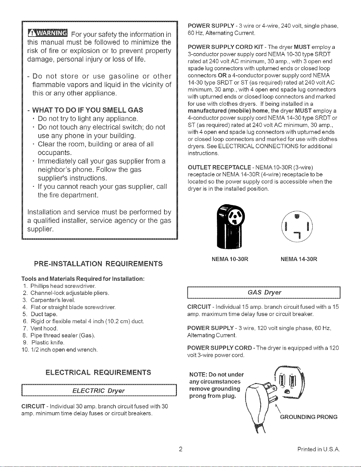
OUTLET RECEPTACLE - NEMA 10-30R (3-wire)
receptacle or NEMA 14-30R (4-wire) receptacle to be
located so the power supply cord is accessible when the
dryer is in the instaNed position.
Installation and service must be performed by
a qualified installer, service agency or the gas
supplier.
PRE-INSTALLATION REQUIREMENTS
Tools and Materials Required for Installation:
1. Phillips head screwdriver.
2. Channel-lock adjustable pliers.
3. Carpenter's level.
4. Flat or straight blade screwdriver.
5. Duct tape.
6. Rigid or flexible metal 4 inch (10.2 cm) duct.
7. Vent hood.
8. Pipe thread sealer (Gas).
9. Plastic knife.
10.1/2 inch open end wrench.
ELECTRICAL REQUIREMENTS
i ELECTRIC Dryer
NEMA 10-30R NEMA 14-30R
GAS Dryer
CIRCUIT - Individual 15 amp. branch circuit fused with a 15
amp. maximum time delay fuse or circuit breaker.
POWER SUPPLY - 3 wire, 120 volt single phase, 60 Hz,
Alternating Current.
POWER SUPPLY CORD - The dryer is equipped with a 120
volt 3-wire power cord.
NOTE: Do not under
any circumstances
remove grounding
i
prong from plug.
CIRCUIT- Individual 30 amp. branch circuit fused with 30
amp. minimum time delay fuses or circuit breakers.
GROUNDINGPRONG
2 Printed in U.S.A.
EXHAUST SYSTEM REQUIREMENTS
Use only 4 inch (10.2 cm) diameter (minimum) rigid or
flexible metal duct and approved vent hood which has a
swingzout damper(s) that open when the dryer is in
operation. When the dryer stops, the dampers automatically
close to prevent drafts and the entrance of insects and
rodents. To avoid restricting the outlet, maintain a minimum
of 12 inches (30.5 cm) clearance between the vent hood
and the ground or any other obstruction.
The following are specific requirements
for proper and safe operation of your dryer. Failure to
follow these instructions can create excessive drying
times and fire hazards.
Number
of
90°
Turns
0
1
2
3
4
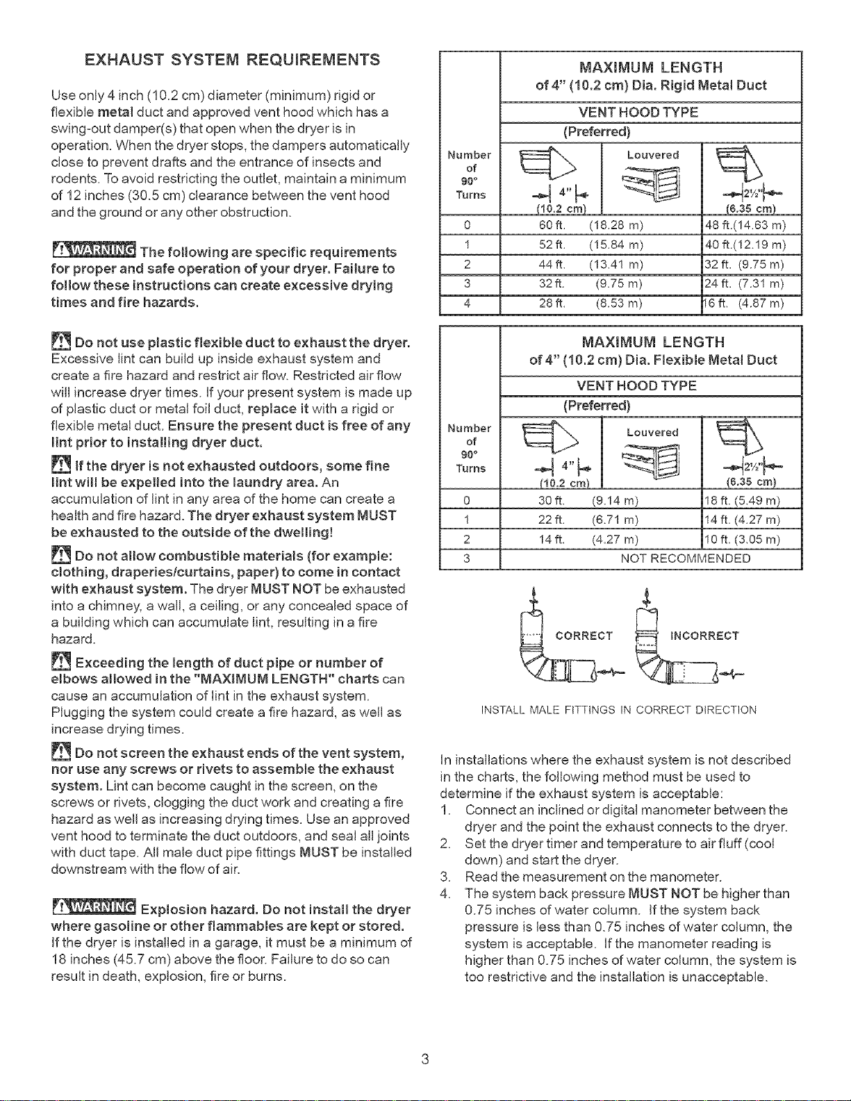
MAXIMUM LENGTH
of 4" (10.2 cm) Din. Rigid Metal Duct
VENT HOOD TYPE
(Preferred)
_4'_._ _Louvered
-,4
(10.2 cm)
60ft, (18,28 m)
52ft. (15,84 m)
44ft, (13,41 m)
32 ft. (9.75 m)
28ft, (8.53 m)
48 ft.(14.63 m)
40 ft.(12.19 m)
32 ft, (9.75 m)
24 ft, (7.31 m)
16ft, (4.87 m)
(&38 cm)
Do not use plastic flexible duct to exhaust the dryer.
Excessive lint can build up inside exhaust system and
create a fire hazard and restrict air flow. Restricted air flow
will increase dryer times, if your present system is made up
of plastic duct or metal foil duct, replace it with a rigid or
flexible metal duct. Ensure the present duct is free of any
lint prior to installing dryer duct.
If the dryer is not exhausted outdoors, some fine
lint will be expelled into the laundry area. An
accumulation of lint in any area of the home can create a
health and fire hazard. The dryer exhaust system MUST
be exhausted to the outside of the dwellin!!
Do not allow combustible materials (for example:
clothing, draperies/curtains, paper) to come in contact
with exhaust system. The dryer MUST NOT be exhausted
into a chimney, a wall, a ceiling, or any concealed space of
a building which can accumulate lint, resulting in a fire
hazard.
Exceeding the length of duct pipe or number of
embows almowed in the "MAXIMUM LENGTH" charts can
cause an accumulation of lint in the exhaust system.
Plugging the system could create a fire hazard, as well as
increase drying times.
[_ Do not screen the exhaust ends of the vent system,
nor use any screws or rivets to assemble the exhaust
system. Lint can become caught in the screen, on the
screws or rivets, clogging the duct work and creating a fire
hazard as well as increasing drying times. Use an approved
vent hood to terminate the duct outdoors, and seal all joints
with duct tape. All male duct pipe fittings MUST be installed
downstream with the flow of air.
Explosion hazard. Do not instatl the dryer
where gasoline or other flammables are kept or stored.
If the dryer is installed in a garage, it must be a minimum of
18 inches (45.7 cm) above the floor. Failure to do so can
result in death, explosion, fire or burns.
MAXIMUM LENGTH
of 4" (10.2 cm) Din. Flexible Metal Duct
VENT HOOD TYPE
(Preferred)
Number
of
96°
Turns
o
1
2
3
INSTALL MALE FITTINGS IN CORRECT DIRECTION
.> Louvered
-q4-F
!16.2 era!!
30ft. (9.14 m)
22 ft. (6.71 m)
14ft. (4,27 m)
(&38 cm)
18 ft. (5.49 m)
14 ft. (4.27 m)
10 ft, (3,05 m)
NOT RECOMMENDED
In installations where the exhaust system is not described
in the charts, the following method must be used to
determine if the exhaust system is acceptable:
1. Connect an inclined or digital manometer between the
dryer and the point the exhaust connects to the dryer.
2. Set the dryer timer and temperature to air fluff (cool
down) and start the dryer.
3. Read the measurement on the manometer.
4. The system back pressure MUST NOT be higher than
0.75 inches of water column. If the system back
pressure is less than 0.75 inches of water column, the
system is acceptable. If the manometer reading is
higher than 0.75 inches of water column, the system is
too restrictive and the installation is unacceptable.
Althoughverticalorientationoftheexhaustsystemis
acceptable,certainextenuatingcircumstancescouldaffect
theperformanceofthedryer:
• Onlytherigidmetalductworkshouldbeused.
• Ventingverticalthrougharoofmayexposetheexhaust
systemtodowndraftscausinganincreaseinvent
restriction.
• Runningtheexhaustsystemthroughanuninsulated
areamaycausecondensationandfasteraccumulation
oflint.
• Compressionorcrimpingoftheexhaustsystemwill
causeanincreaseinventrestriction.
Theexhaustsystemshouldbeinspectedandcleaneda
minimumofevery18monthswithnormalusage.Themore
thedryerisused,themoreoftenyoushouldcheckthe
exhaustsystemandventhoodforproperoperation.
EXHAUSTDIRECTION
Alldryersshippedfromthefactoryaresetupforrear
exhausting.However,onelectricdryers,exhaustingcanbe
totherightorleftsideofthecabinetorthebottomofthe
dryer.Ongasdryers,exhaustingcanbetotherightsideof
thecabinetorthebottomofthedryer.Directional
exhaustingcanbeaccomplishedbyinstallingExhaustKit,
P/N131456800,availablethroughyourpartsdistributor.
Followtheinstructionssuppliedwiththekit.
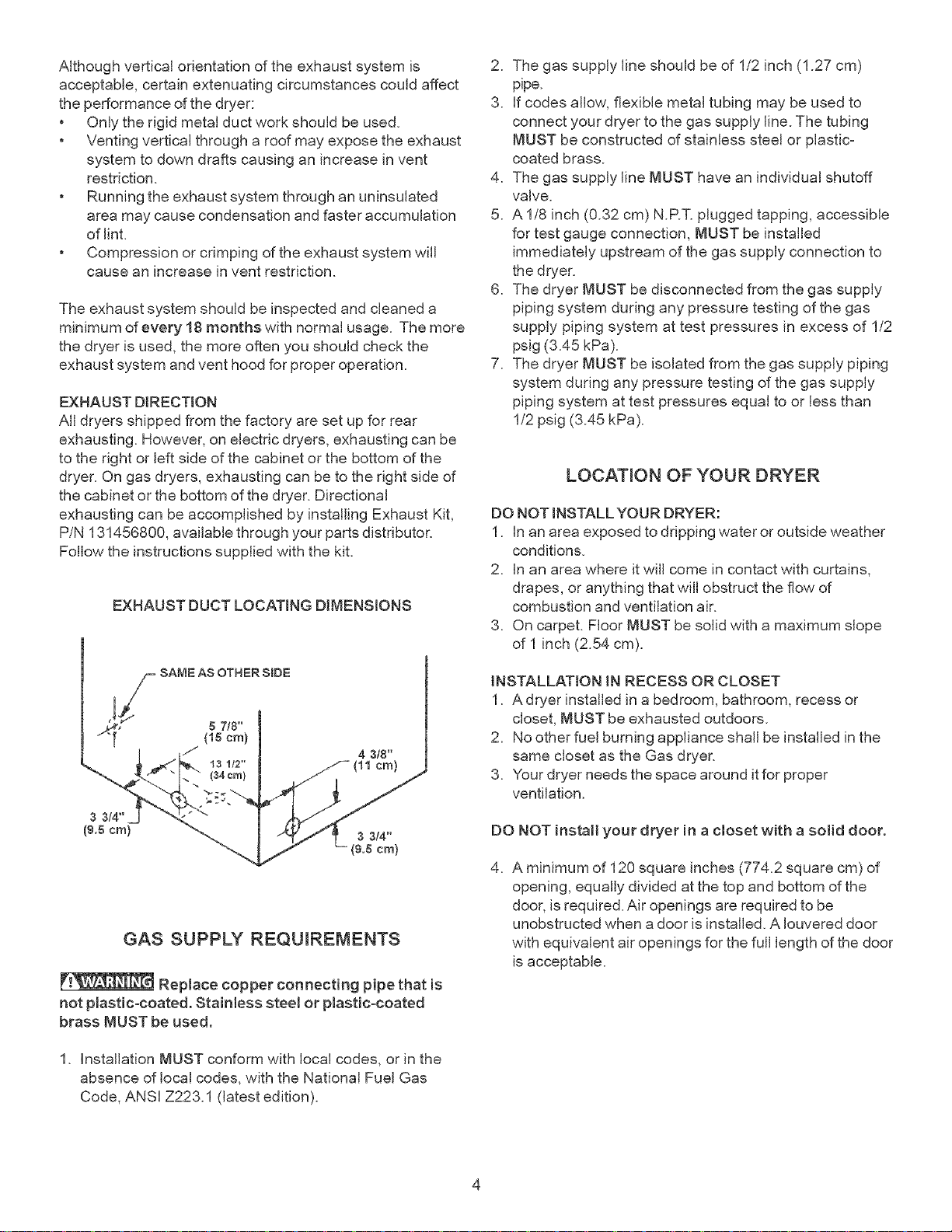
EXHAUSTDUCTLOCATINGDIMENSIONS
2. The gas supply line should be of 1/2 inch (1.27 cm)
pipe.
3. if codes allow, flexible metal tubing may be used to
connect your dryer to the gas supply line. The tubing
MUST be constructed of stainless steel or plastic-
coated brass.
4. The gas supply line MUST have an individual shutoff
valve.
5. A 1/8 inch (0.32 cm) N.RT. plugged tapping, accessible
for test gauge connection, MUST be installed
immediately upstream of the gas supply connection to
the dryer.
6. The dryer MUST be disconnected from the gas supply
piping system during any pressure testing of the gas
supply piping system at test pressures in excess of 1/2
psig (3.45 kPa).
7. The dryer MUST be isolated from the gas supply piping
system during any pressure testing of the gas supply
piping system at test pressures equal to or less than
1/2 psig (3.45 kPa).
LOCATION OF YOUR DRYER
DO NOT [NSTALLYOUR DRYER:
1. [nan area exposed to dripping water or outside weather
conditions.
2. In an area where it will come in contact with curtains,
drapes, or anything that will obstruct the flow of
combustion and ventilation air.
3. On carpet. Floor MUST be solid with a maximum slope
of I inch (2.54 cm).
4 3/8"
cm)
3 3/4"
(9.5 cm)
GAS SUPPLY REQUIREMENTS
Replace copper connecting pipe that is
not plastic-coated. Stainless steel or plastic-coated
brass MUST be used.
1. Installation MUST conform with local codes, or in the
absence of local codes, with the National Fuel Gas
Code, ANSI Z223.1 (latest edition).
iNSTALLATION IN RECESS OR CLOSET
1. A dryer installed in a bedroom, bathroom, recess or
closet, MUST be exhausted outdoors.
2. No other fuel burning appliance shah be installed in the
same closet as the Gas dryer.
3. Your dryer needs the space around itfor proper
ventilation.
DO NOT install your dryer in a closet with a solid door.
4. A minimum of 120 square inches (774.2 square cm) of
opening, equally divided at the top and bottom of the
door, is required. Air openings are required to be
unobstructed when a door is installed. A [ouvered door
with equivalent air openings for the full length of the door
is acceptable.
 Loading...