

Kenmore 41740412701, 41740412703 Installation Guide
®
Inst ll tion
Instructions
Instrucciones
para la instalad6n
Before beginning installation, carefully read these instructions. This will simplify the installation and ensure the washer is installed
correctly and safely. Leave these instructions near the washer after installation for future reference.
NOTE: The electrical service to the washer must conform with local codes and ordinances and the latest edition of the National
Electrical Code, ANSI/NFPA 70 or in Canada, CSA C22.1 Canadian Electrical Code Part 1.
Antes de comenzar la instalacion, lea estas instrucciones con atendon. Le facilitaran la instaladbn y aseguraran que la lavadora sea
instalada correctamente y de manera segura. Guarde estas instrucdones cerca de la lavadora una vez terminada la instaladbn para
referirse a elias en el futuro.
NOTA: el suministro electrico de su lavadora debe estar conforme con los codigos y ordenanzas locales y la edicion mas reciente del
National Electrical Code {Codigo Electrico Nacional), ANSI/NFPA 70, o en Canada, la edition mas reciente del Canadian Electrical Code
(Codigo Electrico de Canada).
_For your safety the information in this manual must be followed to minimize the risk of fire or explosion or to prevent
property damage, personal injury or loss of life.
Do not store or use gasoline or other flammable vapors and liquid in the vicinity of this or any other appliance.
WHAT TO DO IF YOU SMELL GAS
Do not try to light any appliance.
Do not touch any electrical switch; do not use any phone in your building.
Clear the room, building or area of all occupants.
Immediately call your gas supplier from a neighbor's phone. Follow the gas suppliers instructions.
If you cannot reach your gas supplier, call the fire department.
Installation and service must be performed by a qualified installer, service agency or the gas supplier.
Parasuseguridad, siga la informaci6n contenida en estemanual para minimizar el riesgo de incendio o explosi6n
o para evitar da_os materiales, lesiones personales o la muerte.
No guarde ni utilice gasolina u otros vapores y licluidos inflamables en las cercanias de este ni cualcluier otro electrodomestico.
- (2UEHA CERSI NOTA UN OLORA GAS:
No trate de encender ning_n electrodomestico.
No toque ningOn interruptor electrico; no use ningOn telefono de su edificio.
Haga cluetodo el mundo salga del cuarto, edificio o _irea.
Llame inmediatamente al proveedor del gas desde el telefono de un vecino. Siga las instrucciones del proveedor del gas.
Si no puede ponerse en contacto con el proveedor del gas, Ilame a los bomberos.
La instalaci6n y el servicio deben ser hechos por un instalador capacitado, una agencia de servicios o el proveedor del gas.
Save These Instructions
Sears, Roebuck and Co., Hoffman Estates, IL 60179 U.S.A.
Printed in U.S.A. P/N 134804900 (0706)
Contents
SUBJECT PA GE
Pre-lnstallation Requirements ................................................. 2
Electrical Requirement .......................................... 2
Grounding Requirement ........................................ 2
Water Supply Requirements .......................................... 2
Drain Requirements ................................................ 2
Location Of Your Washer ........................................... 2
Unpacking ...................................................... 2-3
Rough-In Dimensions ............................................. 3
Installation ....................................................... 4
Replacement Parts ............................................... 4
PRE-INSTALLATION REQUIREMENTS
Tools Required for installation:
1. 1/4 in. nut driver
2. 3/8 in. socket with ratchet.
3. 3/8 in. open end wrench.
4. 7/16 in. socket with ratchet.
5. 9/16 in. open end wrench.
6. Channel-lock adjustable pliers.
7. Carpenter's level.
ELECTRICAL REQUIREMENTS
CIRCUIT- Individual, properly polarized and grounded 15 amp.
branch circuit fused with 15 amp. time delay fuse or circuit breaker.
POWER SUPPLY - 2 wire, with ground, 120 volt, single phase, 60
Hz, Alternating Current. NOTE: The use of this washer with power
created by gas powered generators, solar powered generators, wind
powered generators or any other generator other than the local
utility company is not recommended.
WATER SUPPLY REQUIREMENTS
Hot and cold water faucets MUSTbe installed within 42 inches (107
cm) of your washer's water inlet. The faucets MUSTbe 3/4 inch (1.9
cm)garden hose type so inlet hoses can be connected. Water pressure
MUST be between 10 and 120 pounds per square inch (maximum
unbalance pressure, hot vs. cold, 10 psi.) Your water department can
advise you of your water pressure.
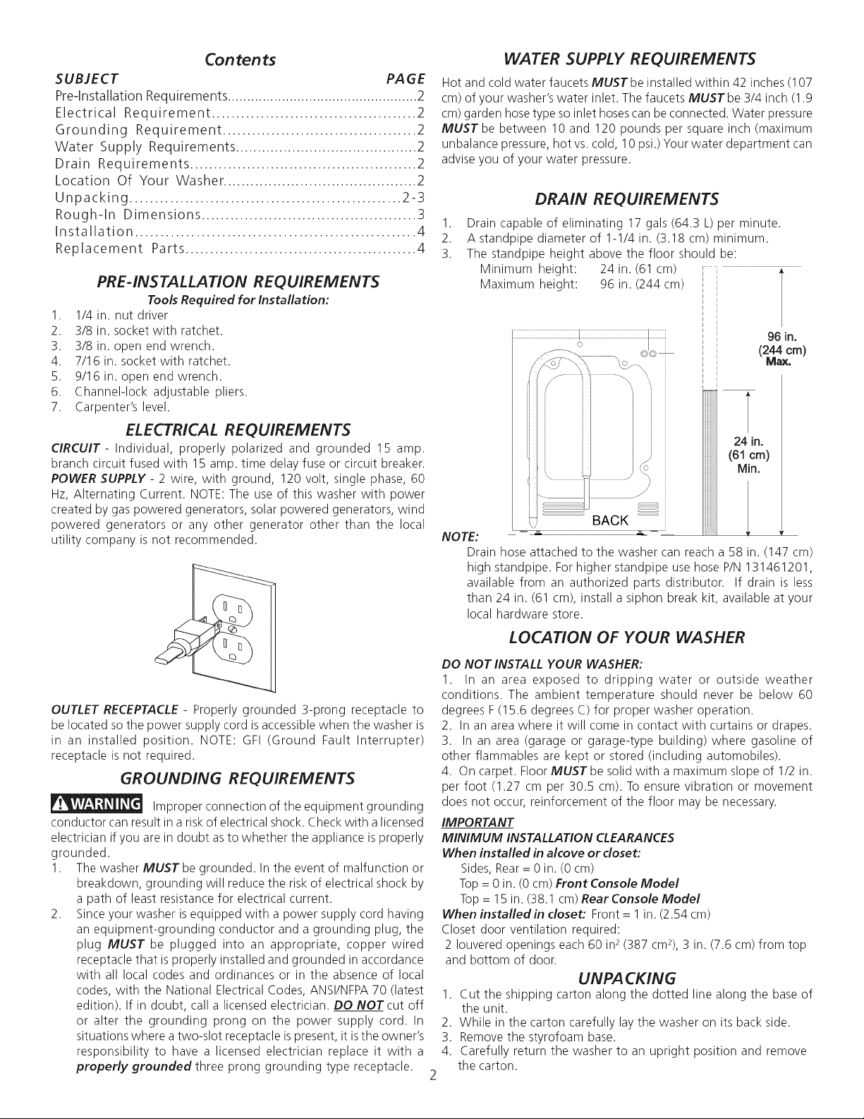
DRAIN REQUIREMENTS
1. Drain capable of eliminating 17 gals (64.3 L) per minute.
2. A standpipe diameter of 1-1/4 in. (3.18 cm) minimum.
3. The standpipe height above the floor should be:
Minimum height: 24 in. (61 cm)
Maximum height: 96 in. (244 cm)
96 m.
(244 cm)
24 in.
(61 cm)
Min.
NOTE:
Drain hose attached to the washer can reach a 58 in. (147 cm)
high standpipe. For higher standpipe use hose P/N 131461201,
available from an authorized parts distributor. If drain is less
than 24 in. (61 cm), install a siphon break kit, available at your
local hardware store.
OUTLET RECEPTACLE - Properly grounded 3-prong receptacle to
be located so the power supply cord isaccessible when the washer is
in an installed position. NOTE: GFI (Ground Fault Interrupter)
receptacle is not required.
GROUNDING REQUIREMENTS
Improper connection of the equipment grounding
conductor can result in arisk of electrical shock. Check with a licensed
electrician if you are in doubt as to whether the appliance is properly
grounded.
1. The washer MUSTbe grounded. In the event of malfunction or
breakdown, grounding will reduce the risk of electrical shock by
a path of least resistance for electrical current.
2. Since your washer is equipped with a power supply cord having
an equipment-grounding conductor and a grounding plug, the
plug MUST be plugged into an appropriate, copper wired
receptacle that is properly installed and grounded in accordance
with all local codes and ordinances or in the absence of local
codes, with the National Electrical Codes, ANSI/NFPA 70 (latest
edition). If in doubt, call a licensed electrician. DO NOTcut off
or alter the grounding prong on the power supply cord. In
situations where atwo-slot receptacle is present, it isthe owner's
responsibility to have a licensed electrician replace it with a
properly grounded three prong grounding type receptacle.
LOCATION OF YOUR WASHER
DO NOT INSTALL YOUR WASHER:
1. In an area exposed to dripping water or outside weather
conditions. The ambient temperature should never be below 60
degrees F (15.6 degrees C) for proper washer operation.
2. In an area where it will come in contact with curtains or drapes.
3. In an area (garage or garage-type building) where gasoline of
other flammables are kept or stored (including automobiles).
4. On carpet. Floor MUST be solid with a maximum slope of 1/2 in.
per foot (1.27 cm per 30.5 cm). To ensure vibration or movement
does not occur, reinforcement of the floor may be necessary.
IMPORTANT
MINIMUM INSTALLATION CLEARANCES
When installed in alcove or doset:
Sides, Rear= 0 in. (0 cm)
Top = 0 in. (0 cm) Front Console Model
Top = 15 in. (38.1 cm) Rear Console Model
When installedin closet: Front= l in. (2.54 cm)
Closet door ventilation required:
2 Iouvered openings each 60 in2(387 cm2),3 in. (7.6 cm) from top
and bottom of door.
UNPACKING
1 Cut the shipping carton along the dotted line along the base of
the unit.
2 While in the carton carefully lay the washer on its back side.
3 Remove the styrofoam base.
4. Carefully return the washer to an upright position and remove
the carton.
5.Carefullymovethewashertowithin4feet(122cm)ofthefinal
location.
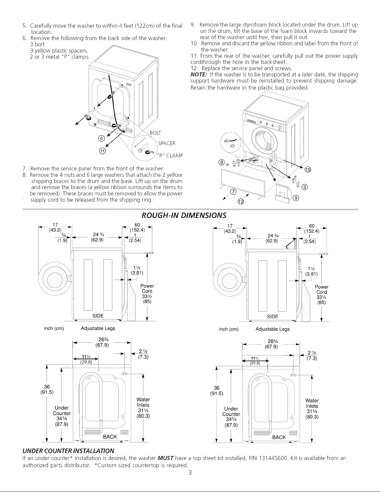
6. Removethefollowingfromthebacksideofthewasher:
3bolt
3yellowplasticspacers,
2or3metal"P"clamps.
7. Remove the service panel from the front of the washer.
8. Remove the 4 nuts and 6 large washers that attach the 2 yellow
shipping braces to the drum and the base. Lift up on the drum
and remove the braces (a yellow ribbon surrounds the items to
be removed). These braces must be removed to allow the power
supply cord to be released from the shipping ring.
9. Removethelargestyrofoamblocklocatedunderthedrum.Liftup
onthedrum,tiltthebaseofthefoamblockinwardstowardthe
rearofthewasheruntilfree,thenpullitout.
10.Removeanddiscardtheyellowribbonandlabelfromthefrontof
thewasher.
11.Fromtherearofthewasher,carefullypulloutthepowersupply
cordthroughtheholeinthebacksheet.
12.Replacetheservicepanelandscrews.
NOTE" If the washer is to be transported at a later date, the shipping
support hardware must be reinstalled to prevent shipping damage.
Retain the hardware in the pla .tic bag provided.
24 3/4
(62.9)
SIDE
inch (cm) Adjustable Legs
263/4
361(91.5)
Under
Counter
345/8
(87.9)
_ 60 _
|(152.4)
.,1
1 "_(2.54)
ROUGH-IN DIMENSIONS
Power
Cord
33V2
(85)
2¼
(7.3)
Water
Inlets
31s/8
(80.3)
(62.9) _
inch (cm) Adjustable Legs
(67.9)
36
(91.5)
Under
Counter
34%
(87.9)
24 3¼
SIDE
263A
._ 60 _
(152.4)
(2.54)
Power
Cord
331/2
(85)
2¼
(7.3)
Water
Inlets
315/8
(80.3)
BACK
UNDER COUNTERINSTALLATION
If an under counter* installation is desired,the washerMUST havea top sheet kit installed, P/N131445600. Kit is availablefrom an
authorized parts distributor. *Custom sizedcountertop is required.
3
 Loading...