

Page 1
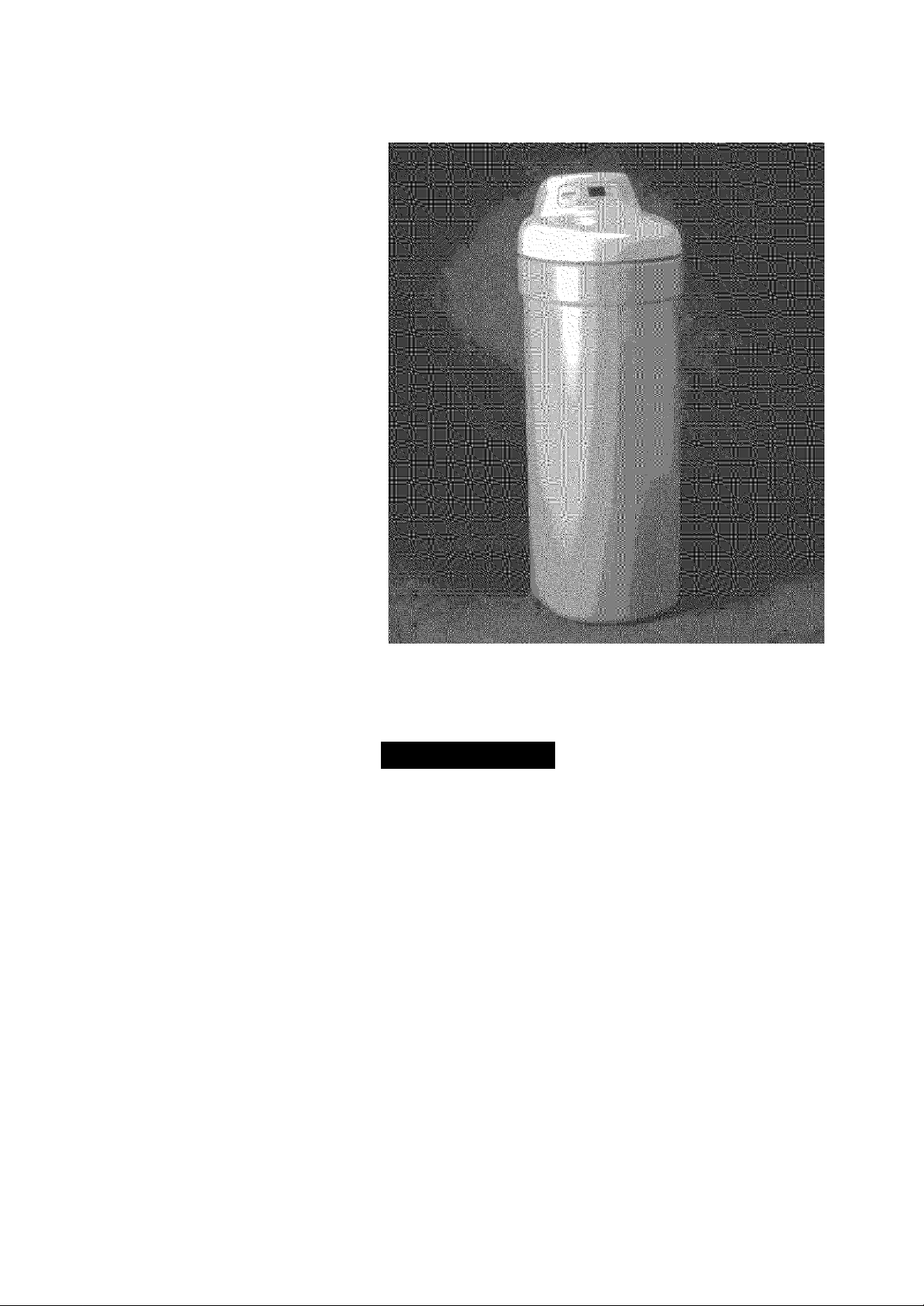
OWNER’S
MODEL NOS.
UltraSoft 275
625.388270 03 UltraSoft 280
625.388280 03
Caution:
Read and Follow
All Safety Rules and
Operating Instructions
Before First Use of
This Product.
If you have questions when
installing, operating or main
taining your softener, and
when setting the timer, call
this toll-free number...
1-800-426-9345
(M - F, 7 am - 8 pm, CST)
For repair or replacement
parts, call this toll-free num
ber...
1-800-366-7278
See back cover for other
Sears service numbers.
www.KenmoreWater.com
SAVE THIS MANUAL
ICeftfiiore
Water Softeners
with Deluxe Valve
♦ Warranty
♦ Start Up / Setting Timer
♦ How It Works
♦ Care Of
♦ Specifications
Systems Tested and Certified by NSF international
♦ Repair Parts
Use the plastic bag and tie provided, to hang manuals
nearby the sotener for future reference.
against NSF/ANSI Standard 44for softener performance.
Sears, Roebuck and Co., 3333 Beverly Road, Hoffman Estates, IL 60179 USA
PRINTED IN U.S.A.
7276547 (Rev. C 8/24/05)
Page 2
WARRANTY
W
A
R
R
A
N
T
Y
ij^jjjjj^jjjjj^jjj
ij^jjjjj^jjjjj^jjj
ij^jjjjj^jjjjj^jjj
ij^jjjjj^jjjjj^jjj
ij^jjjjj^jjjjj^jjj
ij^jjjjj^jjjjj^jjj
>j^j.ij.ij^j.ij.ij^j.ij
SEARS RESIDENTIAL WATER SOFTENER
FULL ONE YEAR WARRANTY ON WATER SOFTENER
For one year from the date of purchase, when this water softener is installed and
maintained in accordance with our instructions, Sears will repair, free of charge,
defects in material or workmanship in this water softener.
FULL TEN YEAR WARRANTY AGAINST LEAKS
For ten years from the date of purchase. Sears will furnish and install a new current
model water softener tank or salt storage drum, free of charge, if either the tank
or drum develop a leak.
TO OBTAIN WARRANTY SERVICE, SIMPLY CONTACT THE NEAREST SEARS
SERVICE CENTER THROUGHOUT THE UNITED STATES. This warranty ap
plies only while this product is in use in the United States.
This warranty gives you specific legal rights, and you may have other rights which
vary from state to state.
Sears, Roebuck and Co., D/817 WA, Hoffman Estates, !L 60179
If you want your water softener professionally installed, talk to your Sears Salesman. He will arrange for a
prompt, quality installation by Sears Authorized Installers.
SEARS INSTALLATION POLICY
All installation labor arranged by Sears shall be per
formed in a neat, workmanlike manner in accor
dance with generally accepted trade practices. Fur
ther, all installations shall comply with all local
laws, codes, regulations, and ordinances. Custom
ers shall also be protected, during installation, by in
surance relating to Property Damage, Workman's
Compensation and Public Liability.
FACTS AND FIGURES TO KEEP
Fill in the blanks below and keep this book in a safe place so you always have
these facts.
Water Softener Model No.t
Serial Number
Date Installed
Water Hardness_
Iron Content
pH
___________
Water Pressure
Water Flow Rate
________________________________________
___
Taste And/Or Odor
_
______________________________
_Grains Per Gallon
_Pounds/Square Inch
Gallons Per Minute
In addition to any warranty extended to you on the
Sears merchandise involved, which warranty be
comes effective the date the merchandise is
installed, should the workmanship of any Sears ar
ranged installation prove faulty within one year.
Sears will, upon notice from you, cause such faults
to be corrected at no additional cost to you.
Parts Per Million
SEARS INSTALLATION WARRANTY
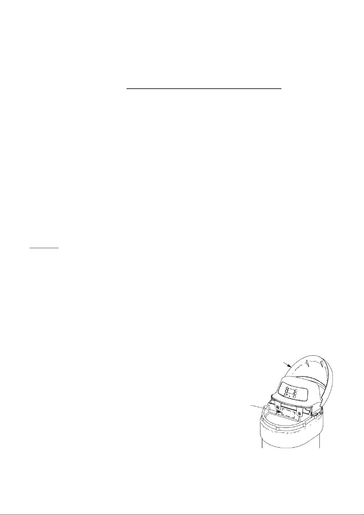
salt hole cover
rating
decal
t The model number is on the rating decal, located on the rim, under the salt hole cover.
A
Page 3
TABLE OF CONTENTS
T
A
L
E
O
F
C
O
N
SECTION 1
A.
B.
C.
D.
E.
Safety Guides------------------------------------------------------------------------- 1-1
Check List of Step-By-Step Guides To Install
Program The Timer......................................................................... 1-3, 1-4
Sanitizing The Water Softener
Adding Salt To The Storage Tank
SECTION 2
A.
B.
Faceplate Timer Features
Soft Water Service and Regeneration
SECTION 3
A.
B.
C.
Salt: Adding To The Storage Tank / Salt Bridge
Keeping The Water Softener Clean------------------------------------------------ 3-2
Protect The Water Softener From Freezing
WATER SOFTENER START UP PAGE NO.
...............................
-----------------------------------------------------
--------------------------------------
HOW YOUR WATER SOFTENER WORKS
------------------------------------------------
----------------------------------
CARE OF YOUR WATER SOFTENER
---------------------
--------------------------------------
1-2
1-5
1-6
2-1 to 2-3
2-4 to 2-6
3-1
3-3
N
ij^jjjjj^jjj
ij^jjIuj^jjjjj^jjj
ij^j^ii^^j j jjj^j j j
rj JJ JJ.TJ JJ JJ
ij^jnVj^j j jjj^j j j
J JJJ^J j j
D.
Checklist (Not Getting Soft Water)............................................................... 3-4
SECTION 4
A.
Dimensions / Specifications-------------------------------------------------- 4-p4-2
SECTION 5
A.
B.
C.
Troubleshooting
Rotary Valve Service
Water Flow Through The Softener Valve
SECTION 6
A.
B.
C.
Water Softener Complete------------------------------------------------------- 6-1, 6-2
Brine Valve Assembly
Valve Assembly....................................................................................... 6-5, 6-6
ABOUT YOUR WATER SOFTENER
SERVICE TECH. INFORMATION
-----------------------------------------------------------
----------------------------------------------------------------
......................................
REPAIR PARTS FOR WATER SOFTENER
............................................................................
5-1 to 5-4
5-5
5-6 to 5-8
6-3, 6-4
B
Page 4

S
C
T
o
SECTION 1 I WATER SOFTENER START UP
A safety GUIDES
▲ Read all steps, guides and rules carefully before
installing and using your new water softener. Follow
all steps exactly to correctly install. Failure to follow
them could cause personal injury or property damage.
Reading this book will also help you to get all of the
benefits from your water softener.
A
Your water softener will remove hardness minerals
and “clear water” iron* from water, up to the iimits
shown on page 4-1. It will not remove other types of
iron, acids, tastes and odors, etc. It will not purify pol
luted water or make it safe to drink.
A
Protect the softener and piping from freezing. Dam
age from freezing voids the softener warranty. See
page 3-3.
N
ij^jjjjj^jjjjj^jjj
IJ^J J JJJ^J J J
ij^j jBj^j j jjj^j j j
ij^j j®j^j j jjj^j j j
ij^jjjjj^jjjjj^jjj
>j^j.ij.ij^j.ij.ij^j.ij
J JJJ^J J J
----------------------------
PLEASE READ AND COMPLY WITH THE FOLLOWING
GUIDES TO PREVENT DAMAGE TO THE SOFTENER
OR OTHER PROPERTY, PERSONAL INJURY, OR POS
SIBLE FATAL SHOCK.
A
THIS SOFTENER WORKS ON 24 VOLTS ONLY. BE
SURE TO USE ONLYTHE TRANSFORMER INCLUDED,
AND PLUG IT INTO A NOMINAL 120V, 60 CYCLE
HOUSEHOLD OUTLET THAT IS GROUNDED AND
PROPERLY PROTECTED BY AN OVERCURRENT DE
VICE SUCH AS A CIRCUIT BREAKER OR FUSE. IF
TRANSFORMER IS REPLACED, USE ONLY THE AU
THORIZED SERVICE, CLASS II, 24 VOLT, 10 VA
TRANSFORMER.
A
Unplug the transformer right away if the power
cable should become damaged or frayed. Make re
pairs, or replace transformer, before plugging back
into the power outlet.
A
Always unplug the softener from electrical power
before removing outer valve covers.
CAUTiONS ----------------------------------------
A
This system is not intended to be used for treating
water that is microbioiogicaily unsafe or of unknown
quality without adequate disinfection before or after
the system.
* The capacity to reduce clear water iron is substantiated
by WQA test data.
1 - 1
Problems, Questions? Call 1-800-426-9345 Kenmore Water Line
Page 5
SECTION 1 I WATER SOFTENER START UP
B. CHECK LIST OF gTEP-BY-STEP GUIDES TO INSTALL
To be sure you have done all the steps to install the
softener, read the following list. Refer to the Installa
tion Manual, part no. 7258997, for step-by-step
guides.
Page numbers referred to are in the Installation
Manual unless otherwise noted.
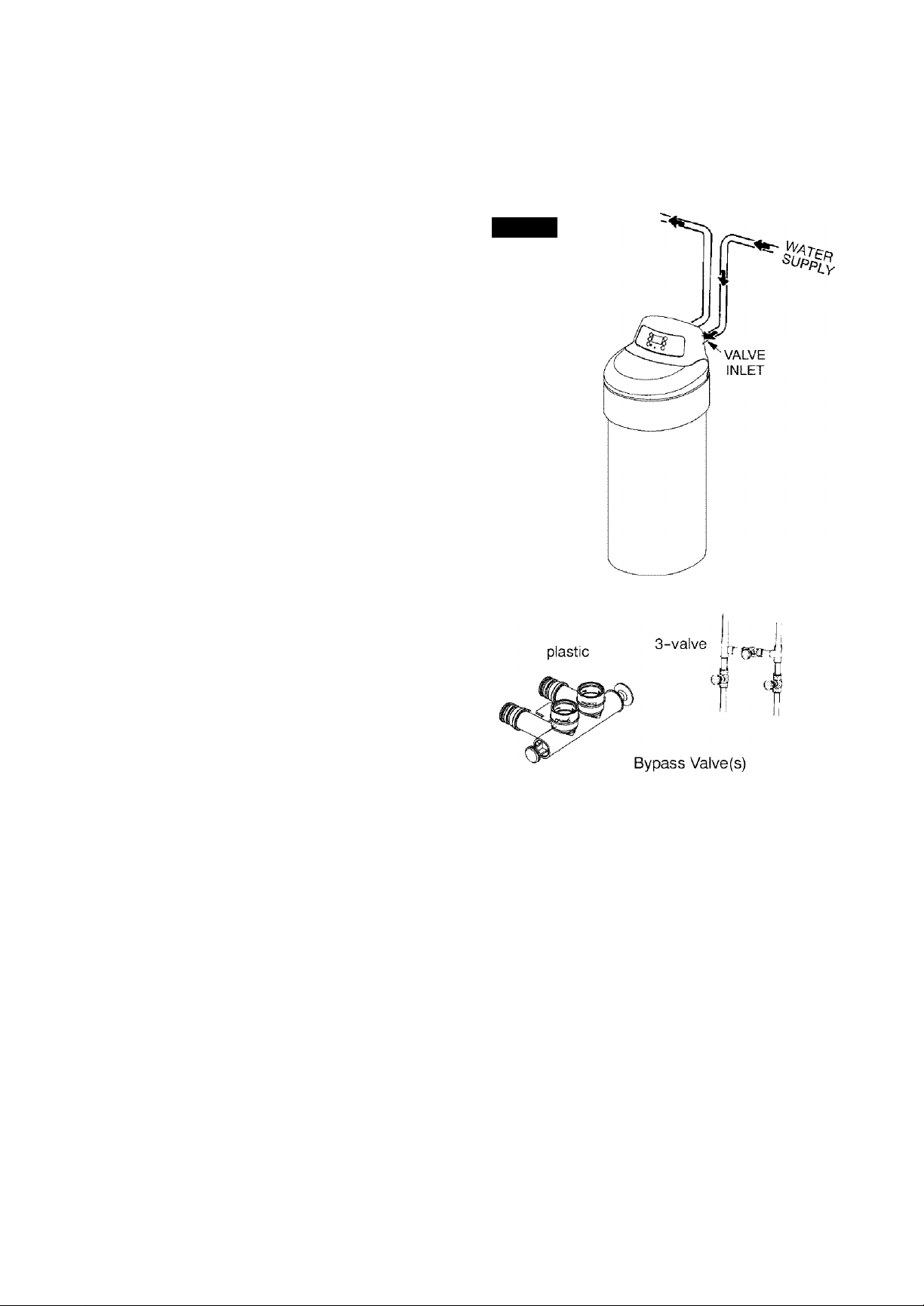
K' Is the house water flow going INTO the softener
valve INLET? Trace piping to be sure. See pages
2-4 and 2-5.
Is the plumbing bypass valve (or 3 valves) set for
SERVICE? Bypass valve(s) should always re
main in soft water service position. Position in
"bypass" only if needed for softener repairs. See
FIG. 14, page 4-1 of this manual.
K' Is the valve drain hose connected the right way,
and without sharp bends or kinks that could
stop or reduce water flow? See page 3-5 in the
installation manual.
Page numbers referred to are in the Installation Manual unless otherwise noted.
FIG. 1
Is the transformer plugged into an inside, al
ways live, grounded, 120V-60Hz electrical out
let? See pages 3-8 and 3-9 in the installation
manual, and the wiring schematic on page 5-1 of
this manual.
K' Be sure to restart the water heater. See page 3-9.
California Efficiency Requirement
Your Kenmore Water Softener has a "Eiigh Effi
ciency" feature with an "ON" or "OFF" setting.
This softener setting is shipped in the "OFF"
position, which utilizes the maximum rated ca
pacity while most often achieving maximum salt
efficiencies. When installing this unit in the State
of California, you MUST turn this setting to the
"ON" position which may initiate more frequent
recharges, however it will operate at 4000 grains
per pound of salt or higher.
If you wish to turn the Salt Efficiency feature
"ON" icon will show in display), follow the
instructions in the Faceplate Timer Features, Sec
tion 2 of this manual.
¿1
NOTE: Codes in the state of Massachusetts require installation
by a licensed plumber. For installation, use plumbing code
248-CMR of the Commonwealth of Massachusetts.
Problems, Questions? Call 1-800-426-9345 Kenmore Water Line
1 - 2
Page 6
SECTION 1 I WATER SOFTENER START UP
C. program THE TIMER
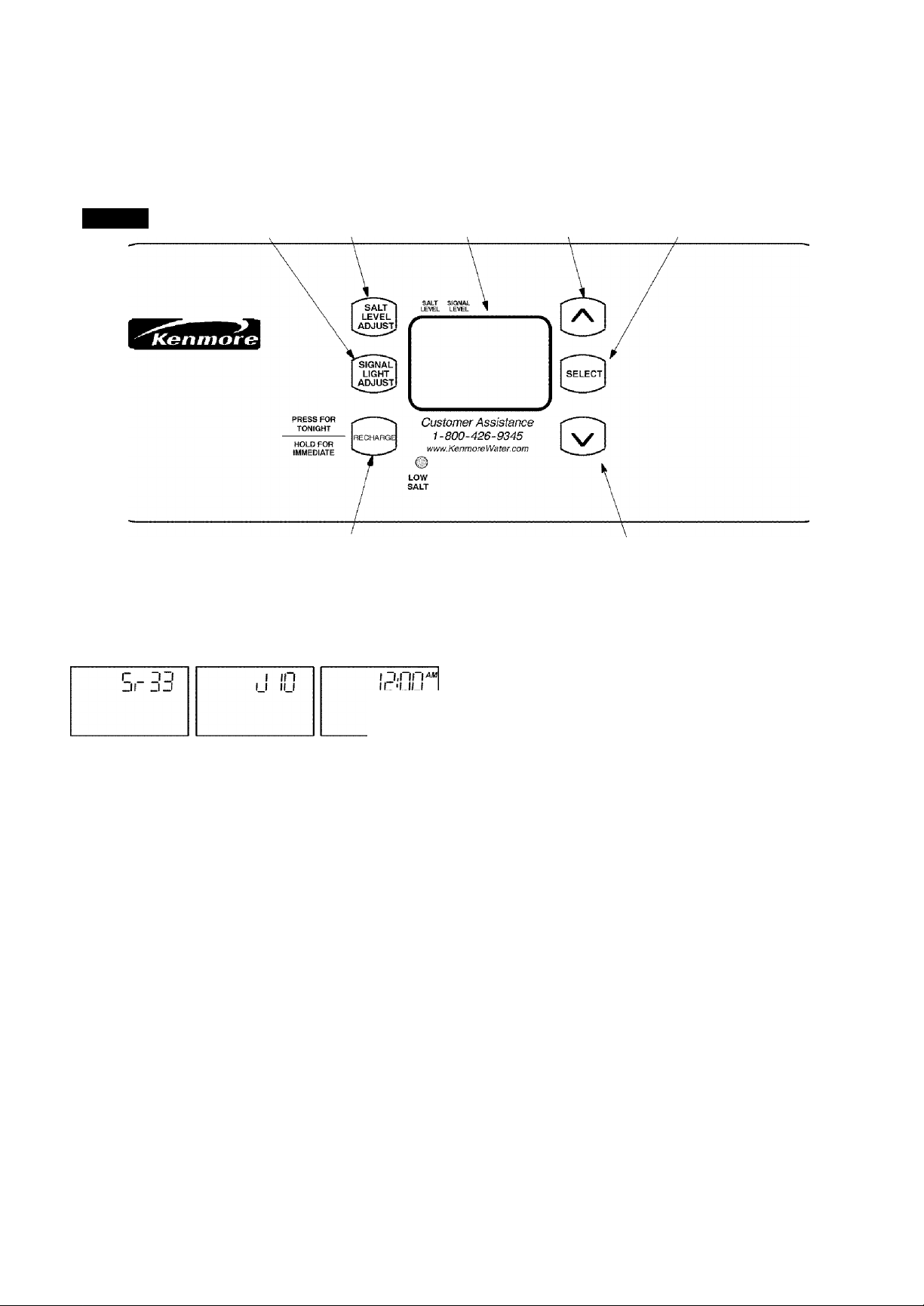
FIG. 2
signal light adjust salt level adjust display button SELECT" button
RECHARGE button
When the transformer is plugged in, a model code,
and a test number (example: JIO) show in the face
plate display for 4 seconds. Then, 12:00 AM and
PRESENT TIME begin to flash.
DOWN button
(step 2), the beeper sounds repeatedly when the dis
play reaches 1 using the DOWN button, or the high
est hardness setting using the UP button.
SET PRESENT TIME OF DAY
PRESENT TiME
Notes:
If SR - - or
-----------
shows in the display, press the
UP0 orDOWNQ button until SR33 shows in the
display. Then, press the SELECT button to set, and
change to the flashing PRESENT TIME display.
To check the model code, unplug the transformer at
the wall outlet and plug in again, if other than this
code shows, see page 5-3 to reset.
SOUND "BEEPER": A "beeper" sounds while
pressing buttons for timer set-up. One beep signals
a change in the face plate display. Repeated beeps
mean the timer will not accept a change from the
button you have pressed, telling you to use another
button. For example, while setting the hardness
If the words PRESENT TIME do not show in the dis
play, press the SELECT button (FIG. 2) until they do,
or see the previous notes.
■ Press the UP or DOWN buttons to set the present
time. Press UP to move the display ahead; press
DOWN to move the time backward.
If the present time is between
noon and midnight, be sure PM
U.rO“
lOLI
PRESENT TIME
shows.
If the present time is between
midnight and noon, be sure AM
I
i lOU
PRESENT TIME
shows.
Each press of the UP or DOWN buttons changes
the time by 1 minute. Fielding the buttons in
changes the time 32 minutes each second.
1 - 3
Problems, Questions? Call 1-800-426-9345 Kenmore Water Line
Page 7

SECTION 1 I WATER SOFTENER START UP
C program THE TIMER
Q SET WATER HARDNESS NUMBER
■ Press the SELECT button once to display 25
(flashing) and HARDNESS.
The grains per gallon (gpg) hard
ness of your water supply is on
your water analysis report. Be
sure to enter water test results on
page A, for future reference.
If your water supply contains iron, compensate for
it by adding to the water hardness number. For ex
ample, assume your water is 20 gpg hard and contains 2
ppm iron. Add 5 to the hardness number for each 1 ppm
of iron. In this example, you would use 30 for your hard
ness number.
20 gpg hardness
2 ppm iron X 5 - 10
(times)
+10
30 HARDNESS NUMBER
■ Press the UP or DOWN buttons to set your water
hardness number in the display. The DOWN button
moves the display to 1. The UP button moves the
display to the highest setting (see maximum setting
for your model in the specifications).
Note:
Each press of the UP or DOWN button changes the
display by 1 between 1 and 25. Between 25 and the
highest number, the display changes 5 at a
time.. .25, 30,35, etc. Holding the UP or DOWN but
ton in changes the display twice each second.
Q SET RECHARGE (REGENERATION) TIME
■ Press the SELECT button to display 2;00 AM
(flashing) and RECHARGE TIME.
M II M«"
At the 2:00 AM recharge time
setting, the softener begins re
C'ULl
RECHAi^G£
TIME
generation (see pages 2-4 and
2-5) at 2:00 AM. This is a good
time in most households because water is not being
used (see Automatic Bypass, page 2-6). If a differ
ent recharge time setting would be better for your
household, do the following.
■ Press the UP or DOWN buttons to set the desired
recharge starting hour. Be sure to observe the AMPM as you did when setting the present time of day.
Note:
Each press of the UP or DOWN buttons changes the
display one hour. Holding the buttons in changes
the display twice each second.
■ Press the SELECT button once again, to com
plete initial programming, and the current time of
day shows in the display.
iiB
IF YOU NEED HELP PROGRAMMING THE TIMER, CALL TOLL FREE,
NUMBER 1-800-426-9345.
SEE PAGES 2-1, 2-2 AND 2-3 FOR OTHER FACE PLATE TIMER FEATURES.
1 - 4
Problems, Questions? Call 1-800-426-9345 Kenmore Water Line
Page 8
SECTION 1 I WATER SOFTENER START UP
Care is taken at the factory to keep your water soft
ener clean and sanitary. Materials used to make the
softener will not infect or contaminate your water
supply, and will not cause bacteria to form or grow.
However, during shipping, storage, installing and
operating, bacteria could get into the softener. For
this reason, sanitizing as follows is suggested®
when installing.
The first time you sanitize your softener, be sure
to do all steps in the installation manual, and on
pages 1-2, 1-3 and 1-4 of this manual first.
Note: Be certain the bypass valve is pulled out
to "service" position.
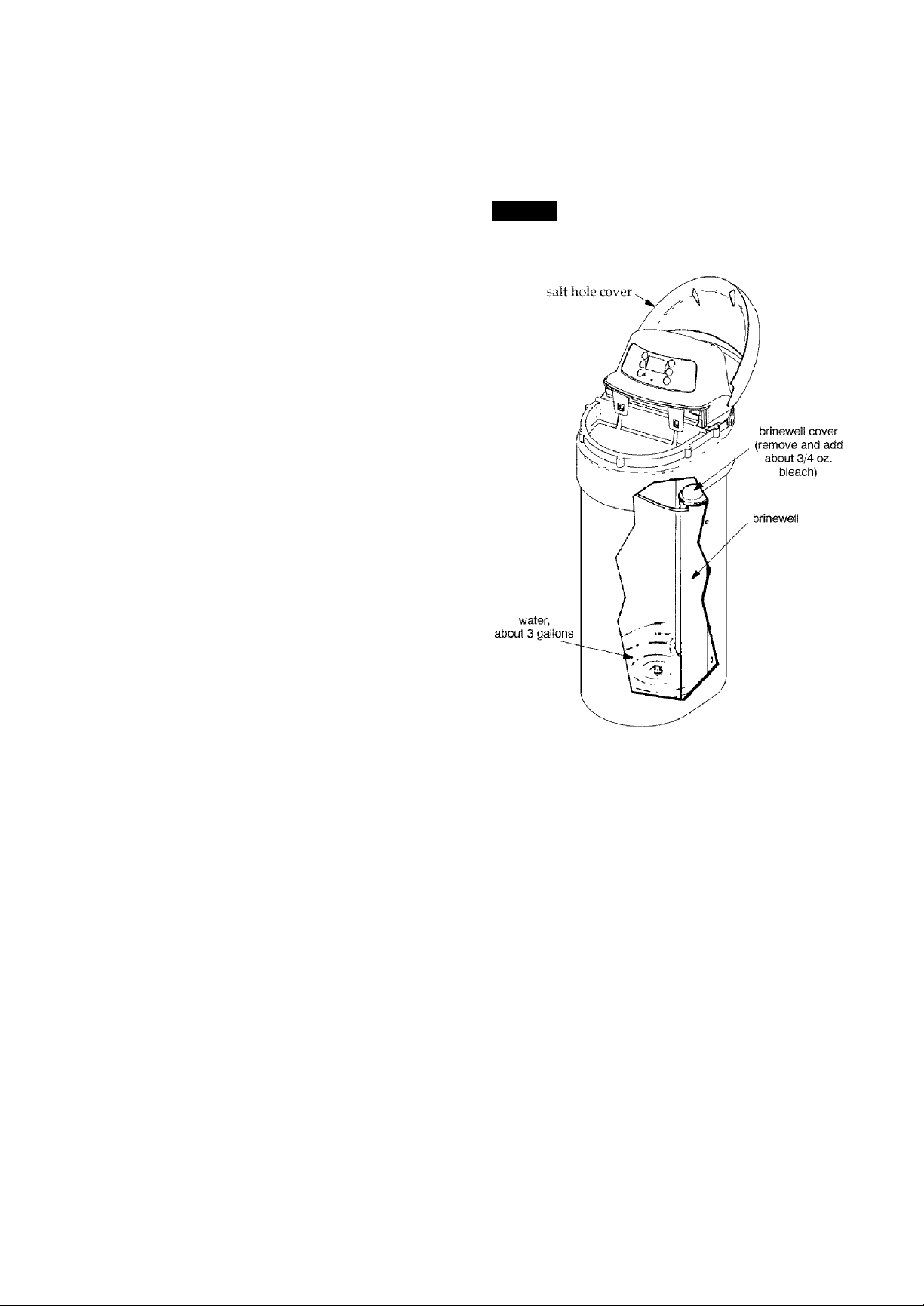
Lift the salt hole cover and use a pail to fill the
salt storage tank with up to 3 gallons of water.
Remove the brinewell cover (FIG. 3) and pour
about 3/4 ounce, or 1 to 2 tablespoons, of com
mon 5.25%, imscented, household bleach (Clorox, Linco, BoPeep, White Sail, Eagle, etc.) in the
softener brinewell. Replace the brinewell cover.
Press the RECHARGE button and hold for 3 se
conds to start a recharge. This first recharge does
several things.
FIG. 3
• It draws the bleach into and through the softener
to sanitize it.
• It fills the salt tank to the water level needed.
• It gets all the air out of the resin tank.
• It prepares the resin bed (see page 2-4) for ser
vice and flushes residual chlorine from the soften
er.
Notes:
This recharge takes about 2-1 /2 or 2- 3/4 hours, de
pending on the salt type setting (page 1-4).
You can sanitize the softener ivith or without salt
in the storage tank.
' Recommended by the Water Quality Association. On some
water supplies, the water softener may need periodic
disinfecting.
1 - 5
Problems, Questions? Call 1-800-426-9345 Kenmore Water Line
Page 9
SECTION 1 I WATER SOFTENER START UP
E. ADDING SALT TO
Brine (salt dissolved in water) is needed for each and
every regeneration. The water for making brine is me
tered into the salt storage tank by the softener.
You must keep salt in the tank, but because the wa
ter softener is very efficient, it is not necessary to
keep it full. Especially in humid areas, it is best to
fill the storage tank one quarter to one half full, and
to refill it more often. Salt bridging (see page 3-1) oc
curs more often when conditions are humid.
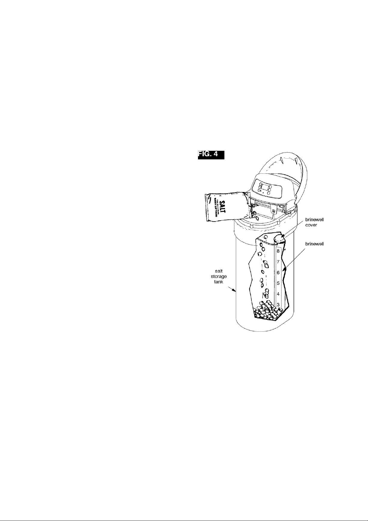
Use NUGGET or PELLET water softener salt. DO
NOT use rock salts, as they have dirt and sediments
that will stop the softener from working.
Before adding salt, be sure the brinewell cover is in
place on the top of the brinewell. It is recommended to
set the salt monitor system, although it is not required
for proper operation (see page 2-1).
Note: The salt monitor system, page 2-1, is calibrated
to the density of nugget or pellet water softener salt.
The monitor will not work as accurately with other
types of salt including rock and solar.
If you choose Potassium Chloride (KCl) as a regener
ant, following these suggestions will help give you
years of maintenance free service.
1) Place only one bag of KCl in your softener at a time
(the salt storage tank should contain no more than 60
pounds of KCl at any one time).
2) A softener using KCl should not be placed in areas
with temperature fluctuations and high humidity
(KCl will harden in these environments and may
make the softener inoperable).
3) Check the brine tank and brine well (black tube in
salt storage tank) monthly. If hardening is present,
pour small amounts of warm water on hardened areas
until they loosen.
4) If your softener does not have a KCl salt setting you
must increase your hardness setting by 25% to ensure
continuous soft water as in example below.
Raw Water Hardenss
(grains per gallon)
5gPg
logpg
ISgpg
20gPg
25gpg
30gPg
35gpg
40gpg
+ 25%
Softener setting when
using KCl
7gPg
13gpg
19gpg
25gPg
32gpg
28gPg
44gpg
SOgpg
THE STORAGE TANK
WATER SOFTENING SALT WITH IRON REMOVING
ADDITIVES — Some salts have an additive to help the
softener handle iron in the water supply These salts
may be used if your water supply has a high iron con
tent. It is recommended to use Sears Resin Bed Clean
er 42- 34426, for periodic treatments to keep your resin
bed clean. This is available at your local Sears store.
Sodium information: Water softeners using sodium
chloride for regeneration add sodium to the water.
Persons who are on sodium restricted diets should
consider the added sodium as part of their overall so
dium intake. For example, if your water supply is 15
grains hard, and you drank 3 quarts of softened water
you would consume 335 milligrams of sodium. That
is equivalent to eating 2-1/2 slices of white bread.
Persons who are concerned about their drinking water
should consider a Kenmore Drinking Water System
that will remove or reduce in excess of 90% of the so
dium and other drinking water contaminants.
1 - 6
Problems, Questions? Call 1-800-426-9345 Kenmore Water Line
Page 10
SECTION 2 HOW YOUR WATER SOFTENER WORKS
yy TIMER FEyXTURES
^ EXTRA RECHARGE
s
c
I
o
N
ij^jjjjj^jjjjj^jjj
IJ^J J JJJ^J J J
rj:.f
ij^j^iPCi^j j jjj^j j j
ij^ j jjj^j j j
ij^jjjjj^jjjjj^jjj
>j^j.ij.ij^j.ij.ij^j.ij
^ RECHARGE NOW
Press the RECHARGE button
and hold unfA ^RECHARGE, Serv
and Fill begin to flash in the display. Upon reaching
fill, the first cycle of regeneration, the flashing Serv
goes off and Fill is on steady. RECHARGE continues
to flash. This regeneration will last for about 2
hours. After the 2 hours, you will have soft water
again.
’^'Note:
If the CLEAN feature is set to ON, a cleaning back
wash {CLEAN and Bkwsh or Rinse flashes in the dis
play, along with the minutes of the dean cycle re
maining) precedes the recharge.
j jjj^j j j
Sometimes, a manually started
regeneration (recharge) may be
desired, or needed. Two exam
ples are:
- You have used more water than
usual (guests visiting) and you
may run out of soft water before
the next timer started regenera
tion.
- You did not refill the softener
with salt before it was gone. After
you refill with salt:
You can start a regeneration right
away, or you can set the timer to
regenerate at the next 2:00 AM (or
other preset recharge time). Do
the following.
M II If
I'LIIJ
RECHARGE
WATER FLOW
^ SALT MONITOR SYSTEM
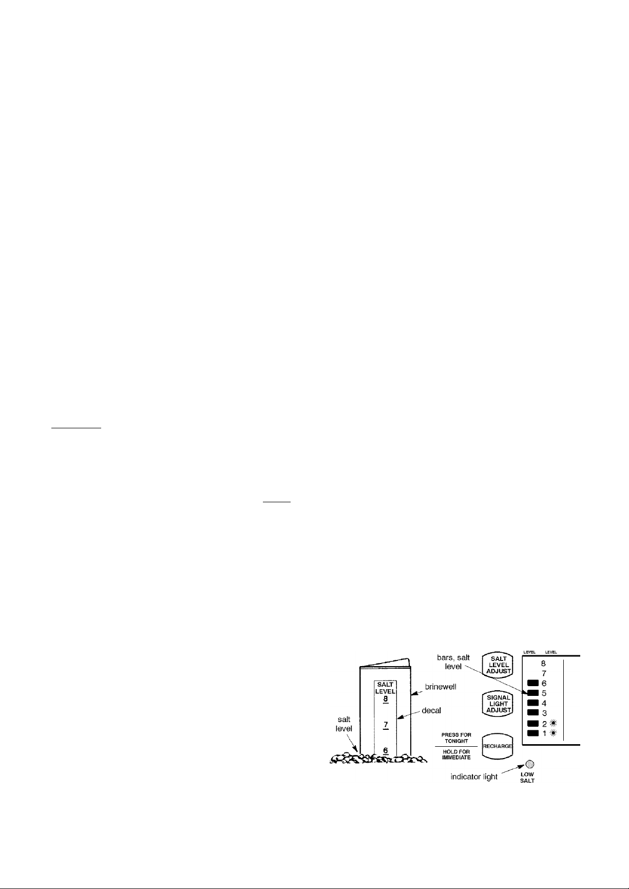
The face plate timer has a low salt monitor with an
indicator light to remind you to add salt to the stor
age tank. To set this monitor system:
Lift the salt hole cover and level the salt in the
storage tank.
The salt level decal, on the brinewell inside the
tank, has numbers from 0 to 8 (see drawing be
low). Observe the number the leveled salt is at
or closest to.
Now, press the SALT LEVEL ADJUST button
until black bars display up to the salt level num
ber. For example, the pictures below show the
salt level at 6.
Finally, set the level you want the low salt indi
cator light to come on. Press the SIGNAL LIGHT
ADJUST button until a (★ ) shows opposite this
number. In the example below, the light will
come on when the stored salt drops to level 2. At
level 2, the storage tank is about 1/3 full. This is
the lowest you should allow the stored salt level
to drop to (see note on page 1-6).
If you wish to turn the salt monitor off, press the
SIGNAL LIGHT ADJUST button until OFF
shows above.
Note:
Your salt monitor is an estimate of your salt level; ac
curacy depends on the type of salt used and other
regeneration characteristics.
^ RECHARGE TONIGHT
Press and release (do not hold) the
RECHARGE button. RE
CHARGE TONIGHT flashes in the display, and the
softener begins regeneration at the next preset re
charge time. Press and release the RECHARGE but
ton once more if you decide to cancel the regenera
tion, and RECHARGE TONIGHT will not flash in
the display.
8
RECHARGE TONIGHT
2
I'IJO
WATER FLOW
Problems, Questions? Call 1-800-426-9345 Kenmore Water Line
2 - 1
Page 11
SECTION 2 HOW YOUR WATER SOFTENER WORKS
A. paceplaTE TIMER FEATURES
^ OPTIONAL SETTINGS - SALT EFFICIENCY,
CLEAN FEATURE, CLEAN FEATURE MINUTES,
MAXIMUM DAYS BETWEEN REGENERA
TIONS and 12 / 24 HOUR CLOCK:
1. To set any of the following options, press and hold
SELECT for 3 seconds until 000 shows in the display.
Then press once until the SALT EFFICIENCY dis
play shows. Use the UP or DOWN buttons to
change the ON / OFF displays.
OFF
Ф
ijn
Ф
□ SALT EFFICIENCY: When this feature is ON,
the unit will operate at salt efficiencies of 4000 grains
of hardness per pound of salt or higher, which will
reduce the softeners salt usage. (May recharge more
often using smaller salt dosage and less water).
When installing this unit in the State of California,
this setting MUST be ON.
2. Press SELECT again to show the CLEAN display.
ncc
urr
un
l_JCFEAN: This feature is beneficial on water sup
plies containing iron and/or high amounts of sedi
ments (sand, silt, dirt, etc.). When set to ON, a back
wash and fast rinse cycle will occur first, proceeding
the normal regeneration sequence (see page 2-4).
This provides extra cleaning of the resin bed before
it is regenerated with the salt brine. To conserve wa
ter, if your water supply does not contain iron or
sediments, be sure this feature is set to OFF. For
UltraSoft 280 the default is ON, for UltraSoft 275 the
default is OFF.
3. Press SELECT again until the CLEAN TIME dis
play shows.
1Ш
Ш
1
|intt
CUM
D
JШ
1Ш
4. Press SELECT again to show the following RE
CHARGE display.
DAt 1 ОДУ
RECHARGE RECHARGE
default display
example: setto 4 days maxi
mum between regenerations
u
^Maximum days betiveen regenerations: The face
plate timer automatically controls regeneration fre
quency (see page 2-5). This provides the greatest
operating efficiency, and under most conditions this
feature will be left in its default mode. However,
you can modify this feature if you want to force a
regeneration every set number of days. For exam
ple, if your water supply contains iron and you
want the softener to regenerate at least once every
few days to keep the resin bed clean, set the display
as typically shown above. Setting is available from
1 to 15 days by using the UP and DOWN buttons.
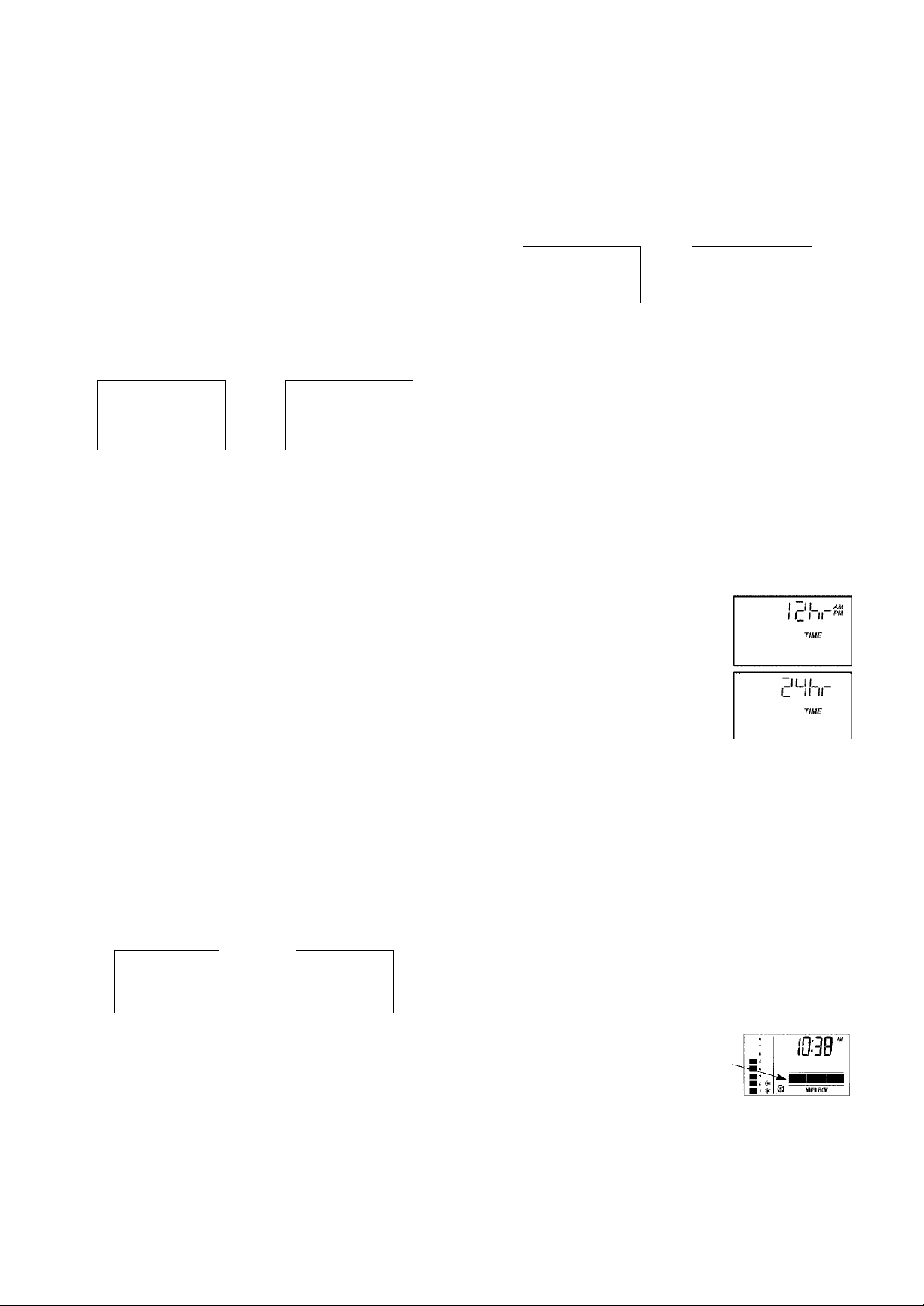
5. Press SELECT to show the 12 HOUR display.
QI2 or 24 hour clock: All time
displays are shown in standard
clock time (1 to 12 PM; and 1 to
12 AM) at the 12 hr default set
ting. If military time displays are
desired, set to 24 hr by pressing
the UP button.
6. Press SELECT to return to the present time dis
play.
^ WATER FLOW THROUGH THE SOFTENER
If soft water is in use, the water
flow bars continually scroll
IS38'
across the display. The bars
scroll slowly when water flow is
slow, and move faster as water
flow increases. The flow bars do
IS38
not show when all faucets and
water using appliances are off.
1038'
default minutes example: time set to 3 minutes
l_\C FEAN feature minutes: If you are using this fea
ture, the length of the extra backwash cycle auto
matically sets to 7 minutes. Flowever, you can ad
just this time from 1 to 15 minutes in length. To
change this cycle time, use the UP button to increase
the time, or the DOWN button to shorten the time.
If no change is desired, continue below.
Problems, Questions? Call 1-800-426-9345 Kenmore Water Line
# ©
Flow bars scroll when
soft water is in use.
2 - 2
Page 12
SECTION 2 I HOW YOUR WATER SOFTENER WORKS
^ RECHARGE TIME REMAINING and VALVE POSITION INDICATORS
One of the valve position indi
cators (Serv, Fill, Brine,
Bkwsh, Rinse) is displayed
while the softener is recharg
ing (See “^Note on page 2-1 if
the CLEAN feature is ON).
valve
position
indicators
tOFF
3
2
A
remaining
SeiV
Fill
Brine
Bkwsh
Bins©
recharge
TIME REmtNI^tG
time
I lio
II IIJM*
RECHAReS
RECHARGE flashes in the
display and, beginning with Brine, the minutes of
recharge remaining before return to service appears
in place of the present time. When the valve is mov
ing from one cycle to another, both position indica
tors are flashing.
^ PROGRAM MEMORY
If electrical power to the softener goes off, the time
display is blank but the face plate timer keeps the
correct time for about 6 hours. When electrical pow
er comes on again, you have to reset the present
time only if the display is flashing. The HARDNESS
and RECHARGE TIME never require resetting un
less a change is desired.Even if the timer is incorrect
after a long power outage, the softener works as it
should to keep your water soft. However, regenera
tions may occur at the wrong time of day until you
reset the timer to the correct time of day (page 1-3).
^ KENMORE'S ULTRA CLEANSING FEATURE (UltraSoft 280 only)
The ultra cleansing feature keeps larger particles of
sediment from entering the home's plumbing sys
tem. As water passes through the softener, the larg
er sediment particles are collected in the integrated
basket and then rinsed to the drain before each re
generation. The ultra cleansing feature provides
added protection for water-using appliances by re
ducing the chance of larger particles entering the
various product's valves and screens.
An extra backwash will be pre- programmed into
the electronics by the factory (see "Clean Feature" in
Section 2 "Faceplate Timer Features" in this manu
al). This extra backwash will help keep the ultra
cleansing feature screen clean.
Important: The ultra cleansing feature is not in
tended to replace pretreatment filtration. For prob
lem water applications, additional sediment filtra
tion is recommended.
Sears offers a full- line of dedicated sediment filtra
tion products including the Whole Home Filter and
Automatic Clarifying Filter.
ultra cleansing screen
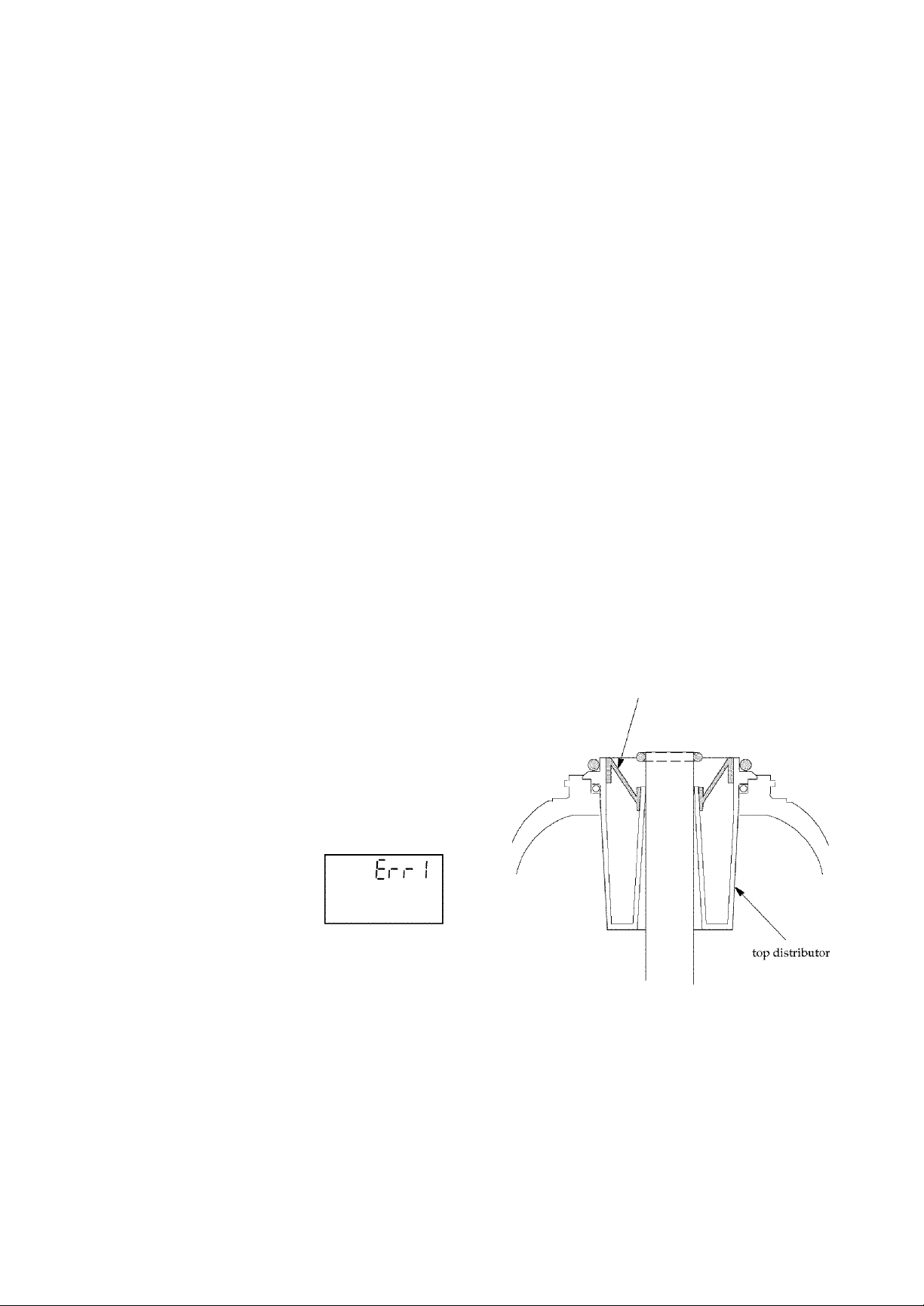
^ ERROR CODE
An error code could appear in
the face plate display if a prob
lem occurs in the softener elec
tronics. Turn to page 5-2 under
"Troubleshooting" to resolve
the problem and/or call the Kenmore Water Line
1-800-426-9345.
Problems, Questions? Call 1-800-426-9345 Kenmore Water Line
2 - 3
Page 13
SECTION 2 HOW YOUR WATER SOFTENER WORKS
B. SOFT WATER SERVICE and REGENERATION
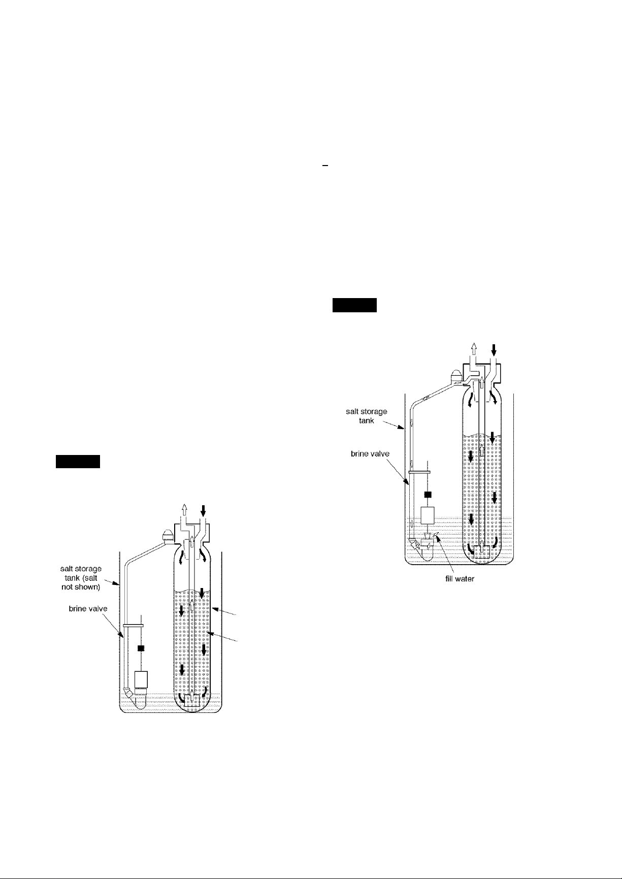
When the softener is giving you soft water, it is
called "Service". During service, hard water comes
from the house main water pipe into the softener.
Inside the softener resin tank is a bed made up of
thousands of tiny, plastic resin beads (FIG. 5). As
hard water passes through the bed, each bead at
tracts and holds the hardness minerals. This is
called ion-exchanging. Water without the hardness
minerals (soft water) flows out of the softener and
into the house soft water pipes.After a period of
time, the resin beads hold all of the hardness miner
als they can, and cleaning with salt brine is needed.
This cleaning is called regeneration or recharge. Re
generation is started at 2:00 a.m. by the electronic
timer (see page 2-6). It takes place in 5 stages or
cycles. These are:
D FILL B BACKWASH
B BRINING
B BRINE RINSE
FAST RINSE
REGENERATIONSERVICE
n FILL: Salt, dissolved in water, is called brine.
Brine is needed to clean the hardness minerals from
the resin beads. To make the brine, water flows into
the salt storage area during the fill stage as shown
in FIG. 6. Fill cycle length depends on how much
soft water making capacity you have used since the
last regeneration. As you use more water, fill time
increases so more brine is made. The greater
amount of brine cleans more hardness minerals
from the resin bed.
FIG. 6
Water Flow Through
the Softener in Fill
soft water hard water
OUT IN
Note:
If the Clean feature is set to ON, additional back
wash and fast rinse cycles occur before the fill cycle.
FIG. 5
Water Flow Through
the Softener in Service
soft water hard water
OUT IN
resin tank
resin bed
2 - 4
Problems, Questions? Call 1-800-426-9345 Kenmore Water Line
Page 14
SECTION 2 HOW YOUR WATER SOFTENER WORKS
B. SOFT WATER SERVICE and REGENERATION
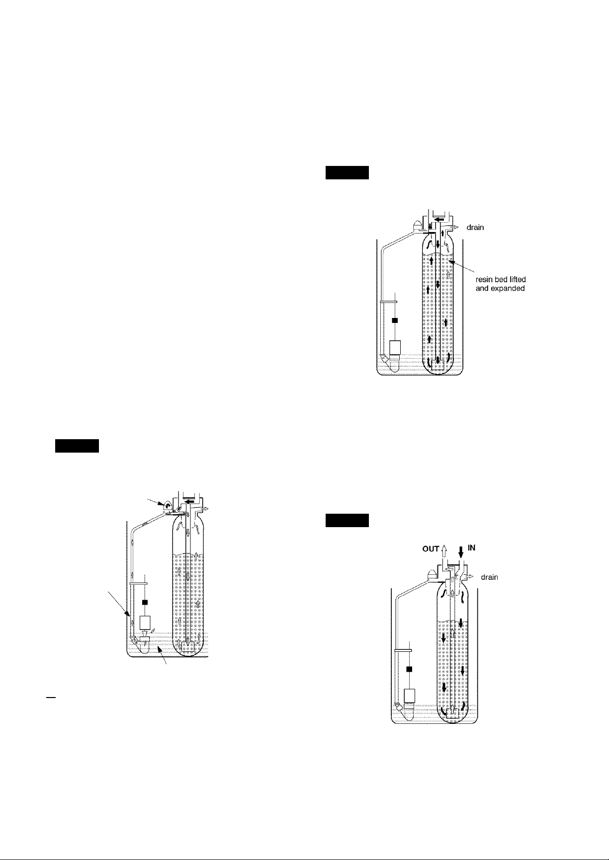
BRINING: During brining, the brine is moved
from the salt storage area, into the resin tank. Inside
the resin tank, brine cleans hardness minerals from
the resin beads and they are discharged out the
drain. How much brine is needed to dean the resin
depends on:
- - the amount of service water used between regen
erations,
- - the amount of resin in the softener,
- -how fast the brine goes through the bed.
The nozzle and venturi (FIG. 7) makes suction to
take brine from the salt tank and put it into the resin
tank. They keep the brine flow down to a very slow
rate to get the best resin cleaning with the least salt.
BRINE RINSE: After all of the brine is moved
into the resin tank, the brine valve closes. Water
keeps flowing the same way it did during brining
except the brine flow has stopped. Hardness miner
als and brine flush from the resin tank to the drain.
Brining and brine rinse together vary in the length
of time they take, relative to the fill cycle length.
FIG. 7
Water Flow Through the Softener
in Brining and Brine Rinse
hard water hard water
bypass OUT ^ ifj
nozzle &
venturi
drain
and to the drain. The bed lifts and expands for good
cleaning.
FIG. 8
Water Flow Through the
Softener in Backwash
hard water hard water
bypass OUT f I IN
FAST RINSE: Backwash is followed by a fast
flow of water down through the resin tank. The fast
flow packs the resin bed and gets it ready for return
to service (FIG. 9).
After fast rinse, the softener returns to service. Hard
water goes into the resin tank where the resin bed
again takes out the hardness minerals. Soft water
goes to the house soft water pipes.
FIG. 9
Water Flow Through the
Softener in Fast Rinse
soft water
hard water
brine valve
brine
El BACKWASH: During backwash, water flows
UP through the resin tank (FIG. 8) at a fast rate to
flush iron minerals, dirt and sediments from the bed
Problems, Questions? Call 1-800-426-9345 Kenmore Water Line
2 - 5
Page 15

SECTION 2 HOW YOUR WATER SOFTENER WORKS
B. SOFT WATER SERVICE and REGENERATION
AUTOMATIC BYPASS
During the brining, brine rinse and backwash cycles
of regeneration, HARD water goes through the soft
ener valve and to the house pipes. If a faucet is
opened, hard water is there for your needs. Howev
er, you should not use hot water, if possible, because
the water heater will refill with hard water. The soft
ener, as factory programmed, regenerates from 2:00
AM to about 4:20 AM, a time when not much water
is used.
If you start your day prior to 4 AM, you may need
to change the recharge starting time. Set the re
charge time to 12:00 AM or 1:00 AM (page 1-4).
Then regeneration will start and end that much ear
lier and your water heater will not refill with hard
water if a hot faucet is opened.
ELECTRONICS
Two main parts of the softener's electronics are [î]
a WATER METER, and [2] a COMPUTER.
[T] WATER METER—The water meter is in the soft
ener valve outlet. As water flows through the meter,
it sends electric pulses to the computer. The com
puter changes the pulses to a measure in gallons of
water.
[2] COMPUTER — The computer is part of the face
plate timer circuit board. It is programmed to know
the softener's capacity (how many grains of hard
ness minerals it will take out of the water before a re
generation is needed). When starting the softener,
page 1-4, you set it for the grains per gallon (gpg)
hardness of the water.
To find a regeneration pattern best for your needs,
the computer uses: (1) water usage from the meter,
(2) hardness setting, (3) softener capacity, and (4)
time since the last regeneration. The computer al
ways adjusts this pattern to your water using hab
its. It works toward providing you with soft water
for the longest time and at the most efficient salt
usage.
Softening capacity is used as hard water goes
through the softener and hardness minerals are re
moved. When the computer determines that only
enough capacity remains to provide soft water up to
the next regeneration starting time (2:00 AM, or as
otherwise set) it will schedule a regeneration. When
the regeneration begins, KELHARGE or RE
CHARGE TIME REMAINING flashes during the re
generation.
^ Note:
If the CLEAN feature is set to ON, a cleaning back
wash {CLEAN and Bkwsh or Rinse flashes in the dis
play, along with the minutes of the clean cycle re
maining), precedes the recharge.
2 - 6
Problems, Questions? Call 1-800-426-9345 Kenmore Water Line
Page 16
SECTION 3
A. SALT: ADDING SALT TO STORAGE TANK, SALT BRIDGE
CARE OF YOUR WATER SOFTENER
s
c
I
o
N
ij,jj j j j
IJ,JJ J J
ij,jj j j j
IJ j j j ,j j j j j
ij^jjjjj^jjjjj^jjj
>j,jj.ij.ij,jj.ij.ij,jj.ij
j jjj^j j j
WHEN TO ADD SALT: The Salt
Monitor System (see page 2-1)
will turn the low salt light
warn you when to refill with salt.
Check for a low salt light a few
weeks after you install the soften
er, and every week after that. Add
salt at about the #2 salt monitor
level. At this level, the tank is
on to
about 1/3 full. Never let the softener use all the salt
before refilling. Without salt, you will soon have
hard water. After filling, reset the Salt Monitor Sys
tem, page 2-1.
Note:
You will have a loss in softening capacity and may
get partly hard water if less than 10 inches (salt mon
itor level 2) of salt is in the storage tank.
PLEASE SEE PAGE 1-6 FOR SALT FILLING DIRECTIONS.
BE SURE TO RESET THE SAET MONITOR, PAGE 2-1.
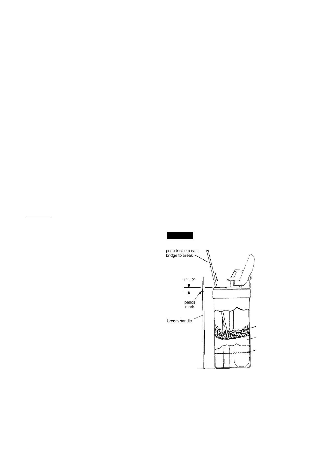
SALT BRIDGE
Sometimes, a hard crust or salt bridge forms in the
salt storage tank. It is usually caused by high hu
midity or the wrong kind of salt. When the salt
bridges, an empty space forms between the water
and salt. Then salt will not dissolve (melt) in the wa
ter to make brine. Without brine, the resin bed does
not regenerate and you will have hard water.
If the storage tank is full of salt, it is hard to tell if you
have a salt bridge. Salt is loose on top, but the bridge
is under it. The following is the best way to check for
a salt bridge.
Salt should be loose all the way to the bottom of the
tank. Hold a broom handle, or like tool, up to the
softener as shown in FIG. 10. Make a pencil mark on
the handle, 1" or 2" below the top height of the rim.
Then, carefully push it straight down into the salt.
If a hard object is felt before the pencil mark gets to
the top of the tank, it's most likely a salt bridge.
Carefully push into the bridge in a few places to
break it. Do not try to break the salt bridge by
pounding on the outside of the salt tank. You may
damage the tank.
FIG. 10 Salt Bridge
salt
salt bridge
water level
If the wrong kind of salt made the bridge, take it out.
Then fill the tank with nugget or pellet salt only.
Problems, Questions? Call 1-800-426-9345 Kenmore Water Line
3 - 1
Page 17
SECTION 3
CARE OF YOUR WATER SOFTENER
CLEAN
NOZZLE & VENTURI
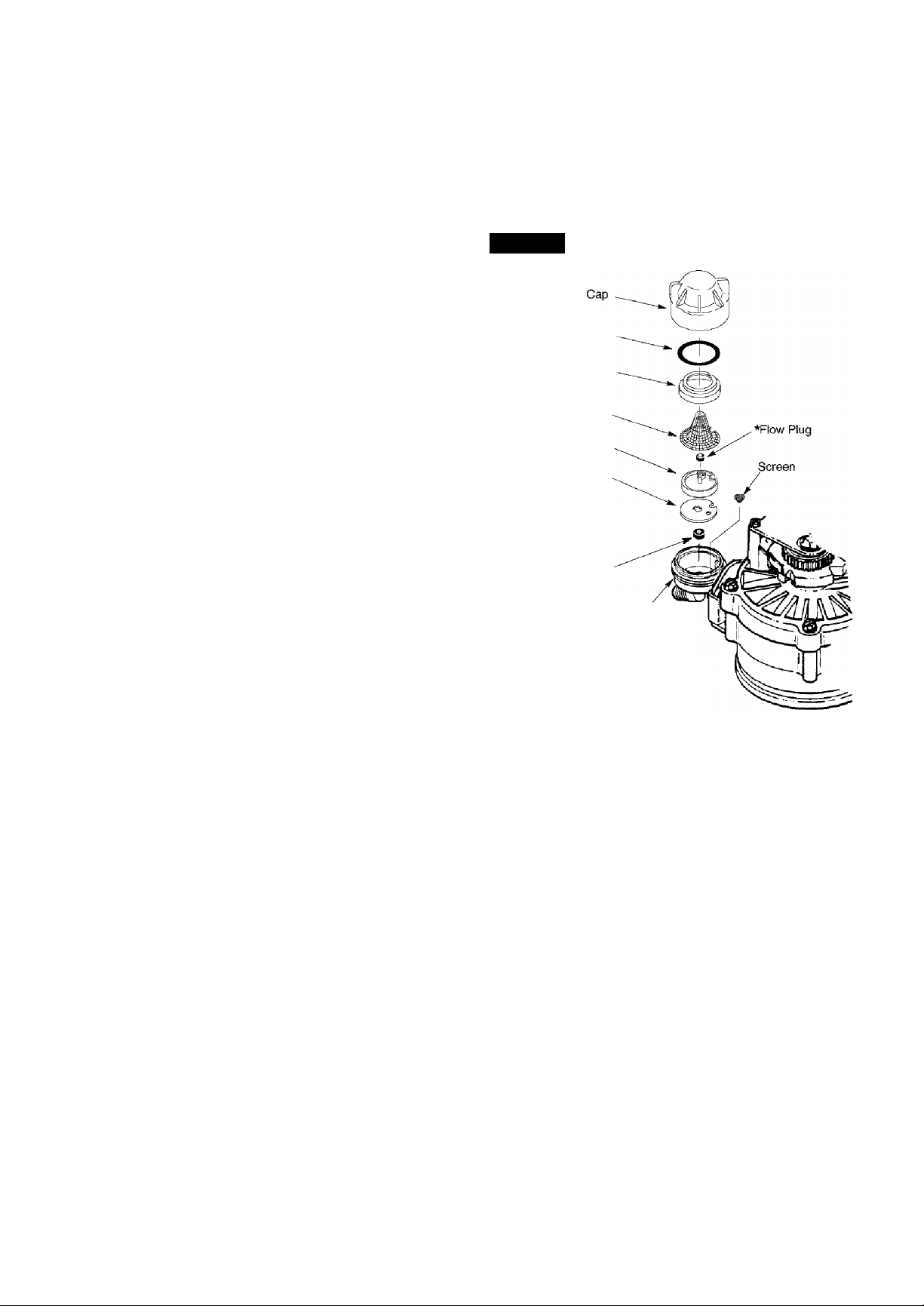
A clean nozzle and venturi (FIG. 11) is a must for the
softener to work right. This small unit moves brine
from the salt storage tank to the resin tank during re
generation. If it becomes plugged with sand, silt,
dirt, etc., the softener will not work and you will get
hard water.
To get to the nozzle and venturi, remove the softener
top cover. Be sure the softener is in service cycle (no
water pressure at nozzle and venturi).
1) Turn off the cap from the nozzle and venturi hous
ing.
2) Lift out the screen support and screen, do not lose
the large o-ring seal.
3) Then the nozzle and venturi. Wash and rinse the
parts in warm water until clean. If needed, use a
small brush to remove iron or dirt. Also check and
clean the gasket, flow plugs and screens.
Carefully replace all parts in the correct order. Lu
bricate the o-ring seal with silicone grease or Vase
line and place in position. Install and tighten the
cap, by hand only. Do not overtighten, which
may break the cap or housing.
FIG. 11
Screen Support
Nozzle & Venturi
IMPORTANT: Be sure small
holes in the gasket are cen
tered directly over the small
holes in the nozzle & venturi
housing,
»Install with numbered side up concave
side down. Be sure the largest flow plug is
located in the nozzle & venturi housing.
Cleaning Nozzle & Venturi
O-ring Seal
Screen
Gasket
»Flow Plug
(HVDC)
Nozzle & Venturi
Housing
IRON FROM RESIN BED
Your water softener takes hardness minerals (cal
cium and magnesium) out of the water. It can also
control some "clear water" iron. See maximum al
lowed in the specifications on page 4-1. With clear
water iron, water from a faucet is clear when first
put into a glass. After 15 to 30 minutes, the waterbe
gins to cloud or turn rust colored. A water softener
WILL NOT remove any iron which makes the water
cloudy or rusty as it comes from the faucet (called
red water iron). To take red water iron out of water,
or over the maximum of clear water iron, an iron fil
ter or other equipment is needed. Your local Sears
store has trained people to help you with iron water
problems.
If your water supply has clear water iron, even
though less than the maximum allowed, regular
resin bed cleaning is needed. Your local Sears store
has resin bed cleaner. Item No. 42-34426 for this.
Clean the bed at least every 6 months. If iron shows
up in the soft water before 6 months, clean more
often. Printed instructions are on the resin bed
cleaner bottle.
3 - 2
Problems, Questions? Call 1-800-426-9345 Kenmore Water Line
Page 18

SECTION 3
CARE OF YOUR WATER SOFTENER
WATER SOFTENER FROM FREEZING
If the softener is installed where it could freeze
(summer cabin, lake home, etc.), you must drain all
water from it to stop possible freeze damage. To
drain the softener:
Close the shut-off valve on the house main wa
ter pipe, near the water meter or pressure tank.
Open a faucet in the soft water pipes to vent
pressure in the softener.
Q Refer to FIG. 14 on page 4-1. Move the stem in
a single bypass valve to bypass. Close the inlet
and outlet valve in a 3-valve bypass system, and
open the bypass valve. If you want water in the
house pipes again, reopen the shut-off valve on
the main water pipe.
Unplug the transformer at the wall outlet. Re
move the salt hole cover and the main cover.
Take off both drain hoses.
Carefully remove the large holding clips at the
softener inlet and outlet (see Key No. 67, on page
6-5). Separate the softener from the copper
tubes, or from the bypass valve.
FIG. 12
Looking at FIG. 12, lay a piece of 2 inch thick
board near the floor drain. Move the softener
close to the drain. SLOWLY and CAREFULLY,
tip it over until the rim rests on the wood block
with the inlet and outlet over the drain.
allow the softener's weight to rest on the inlet
and outlet fittings or they will break.
Drain All Water From Softener
Do not
Remove the brinewell cover and disconnect the
brine valve tubing at the nozzle and venturi as
sembly (see page 3-2). Lift the brine valve out of
the brinewell. Tip the brine valve upside down
to drain water.
Tip the bottom of the softener up a few inches
and hold until all water has drained. Leave the
softener laying like this until you are ready to
use it. Plug the inlet and outlet with rags to keep
dirt, bugs, etc. out.
3 - 3
Problems, Questions? Call 1-800-426-9345 Kenmore Water Line
Page 19
SECTION 3
CARE OF YOUR WATER SOFTENER
D. CHECKLIST ... TO HELP YOU SAVE MONEY
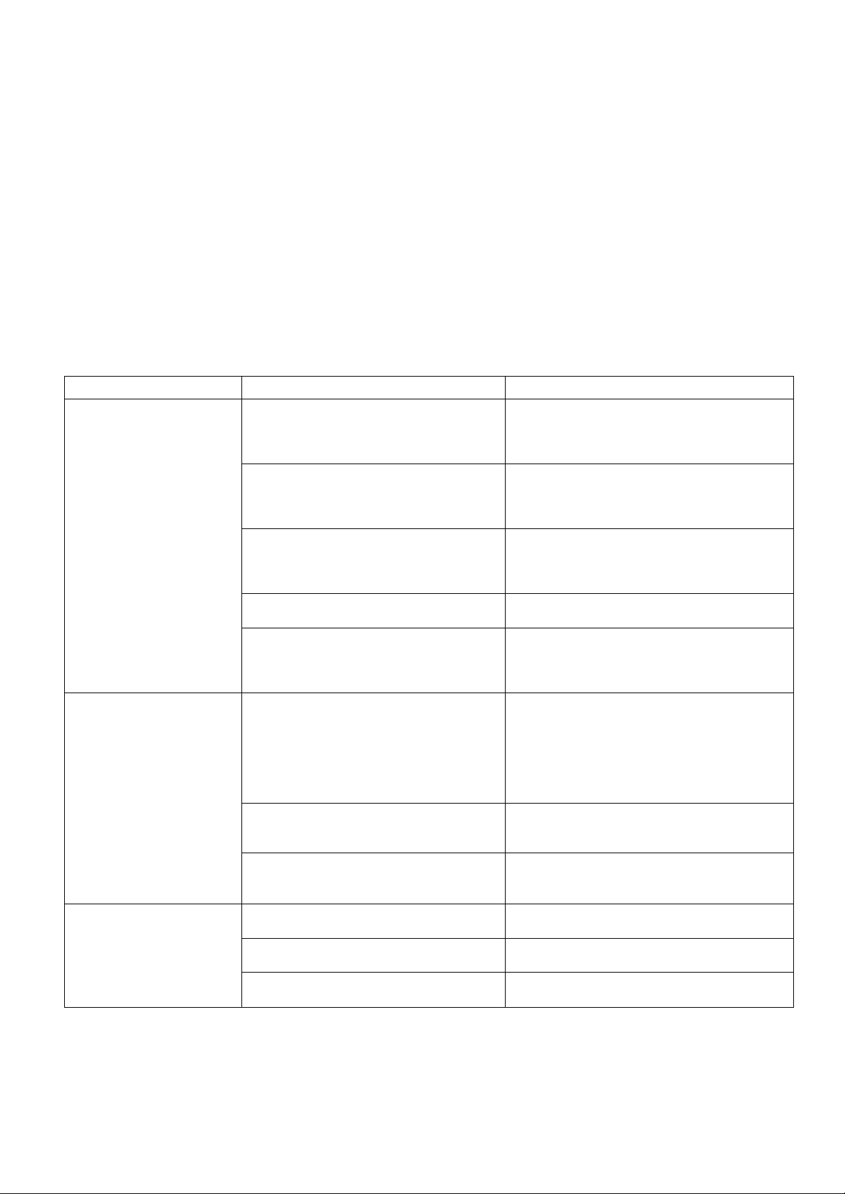
If your water softener fails to work, make the following easy checks. Often, you will find what's wrong your
self and you won't have to call and wait for service. If you do not find anything wrong, while making the
checks, and your softener still does not work, call your Sears Service Department.
Note:
1. Also read ERROR CODE, page 2-3.
2. If an error code is not displayed, press and hold the SELECT button until the display changes. Then, press
the SELECT button again and hold until a flashing SR code appears. It must show SR33. If any other number
shows, the face plate computer is working on incorrect input and would probably be the cause of the problem.
To set SR33, press either the UFIXI or DOWNfvl button. When correct model code shows, press SELECT to
return a flashing 12:00 AM display. Reset the present time, hardness number, etc., pages 1-3 and 1-4.
PROBLEM CAUSE CORRECTION
No soft water
Water hard sometimes
Brine tank fiooded
No salt (or salt bridged) in the storage tank Add salt, or break the salt bridge (page 3-1).
Press ON/OFF-HOLD (RECHARGE NOW)
button and hold for 3 seconds to start a
regeneration (see page 2-1).
Transformer unplugged at the wail outlet,
or power cable leads loose from the
electronic board, fuse blown, circuit
breaker popped, or circuit switched off.
Manual bypass valve(s) in bypass position Look at FIG.Mon page 4-1. Move the stem in
Dirty, plugged or damaged nozzle &
venturi
Valve drain hose plugged or restricted The drain hose must not have kinks, sharp
Check for loss of power due to any of these
and correct. With the power back on, look at
the time display and read PROGRAM
MEMORY, page 2-3.
a single valve to service. In a 3-valve bypass,
open the inlet and outlet valves, and be sure to
fully close the bypass valve.
Take apart and clean or replace damaged
parts (see page 3-2).
bends, or be raised too high above the
softener (see page 16 in your installation
manual).
Hardness number setting too low Press and release the SELECT button until
HARDNESS shows in the display. Read the
hardness number in the display and be sure
the same grains per gallon number is shown
on your water analysis report. See page 1 -4 to
reset. Press and release the SELECT button
until the present time shows in the display.
Using hot water when softener is
regenerating
Increase in the grains of hardness in your
water supply
Restricted drain line Check for kinks, bends or obstructions (see
Plugged or dirty nozzle & venturi Take apart and clean or replace damaged
Valve-rotor disc & seals Check for scratches or grooves, replace if
Avoid using hot water during this time because
the water heater refills with hard water (see
Automatic Bypass, page 2-6).
Ask your Sears retail store for a new water
analysis. Then make a new hardness number
setting (page 1-4).
page 16 in your instaliation manual).
parts (see page 3-2).
needed.
3 - 4
Problems, Questions? Call 1-800-426-9345 Kenmore Water Line
Page 20
SECTION 4
KNOW ABOUT YOUR WATER SOFTENER
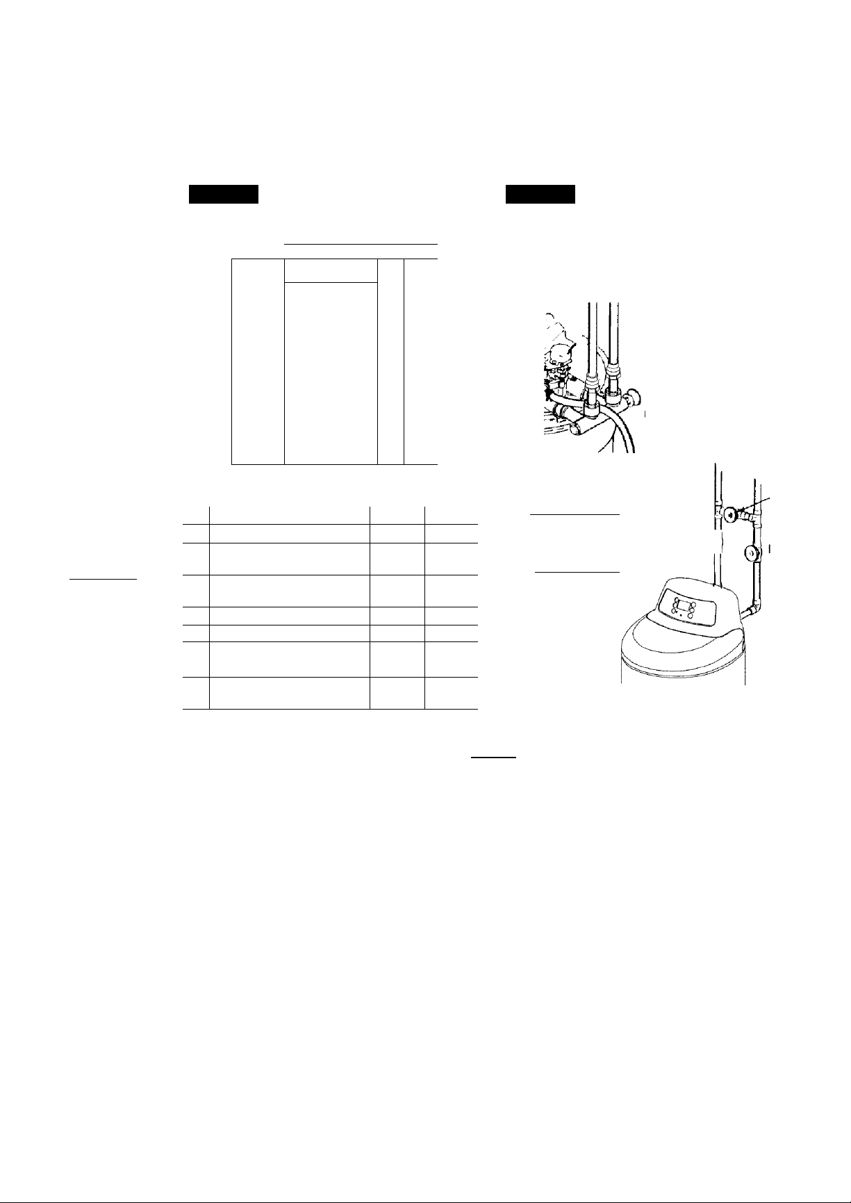
A p||^Ej^3|Q|^3 ! specifications
S
C
T
o
N
IJ^JJJJJ^JJJJJ^JJJ
ij^jjjjj^jjjjj^jjj
J JJJ^J J J
11 t m imi t j I I 11t j I I
ij^jTjKj^j J jjj^j J J
ij^jJjjj^jJjjj^jJJ
>j^j.ij.ij^j.ij.ij^j.ij
FIG. 13
i\
''
1 1
1 ,
1 1
1
A
A Sait Tank Height 40-1/4 102.2
B Resin Tank Diameter
(nominal)
C Resin Tank Height
(nominal)
D Iniet-Outiet Height 41-1/2 105.4
E Overall Height 47-3/4
F1 Length 19-3/4 50.2
p2
Width 16-1/2
—
Distance between inlet-
outlet center lines
1
1
1
1
1
1
1
1 1
i J
\ y
V. y J
Inches
3-3/8 8.6
D
(
1 U
'
CM
10
40 101.6
25.4
121.3
41.9
FIG. 14
BYPASS VALVES
Bypass valve(s) should always remain in soft
water service position. Position in "bypass" only
if needed for softener repairs.
SINGLE BYPASS
PULL STEM
OUTWARD
FOR
SERVICE
Push
nward
For
Bypass
3 - VALVE BYPASS
FOR SERVICE
close bypass valve
open inlet & outlet valves Outlet ^
FOR BYPASS
open bypass valve
close Inlet & outlet valves
Value Vfl
Bypass
Valve
niet
Valve
TIMER SR CODE SR33
WATER SUPPLY TO WATER SOFTENER
Minimum water system flow (gpm)
Minimum-Max. water pressure (psi)
Minimum-Max. water temperature (°F).................................................................... 40-120
Maximum water hardness (gpg)................................................................................. 100
Maximum “clear water” iron (ppm)*
SALT FOR WATER SOFTENER
Type of salt needed
Alternate type of salt........................................................................... pure, evaporated, compacted
............................................................................
.....................................................
........................................................................
-------------------------------------------
3
10
nugget or pellet
20-125
water softener salt
gpm = gallons per minute gpg = grains per gallon
psi = pounds per square inch ppm = parts per million
^Capacity to remove clear water iron is substantiated by WQA test data. State of Wisconsin requires
additional treatment if water supply contains greater than 5 ppm clear water iron.
4 - 1
Problems, Questions? Call 1-800-426-9345 Kenmore Water Line
Page 21
SECTION 4
KNOW ABOUT YOUR WATER SOFTENER
A. DIMENSIONS / SPECIFICATIONS
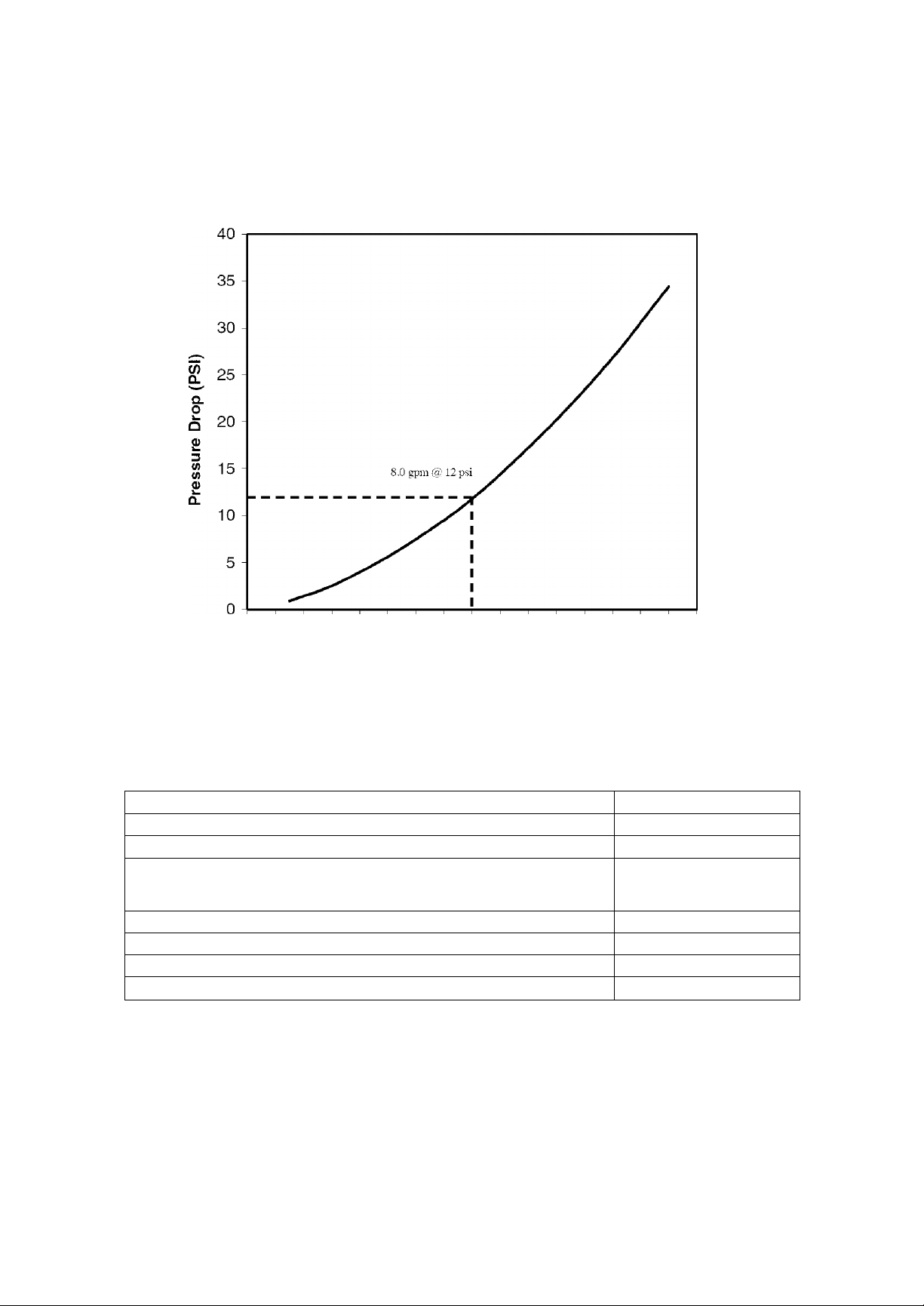
Pressure Drop (PSI) vs. Flow Rate (GPM)
0 1 2 3 4 5 6 7 8 9 10 11 12 13 14 15 16
Flow Rate (GPM)
Intermittent flow rate does not represent the maximum service flow rate used for determining the softeners
rated capacity and efficiency. Continuous operation at flow rates greater than the service flow rate may affect
capacity and efficiency performance.
OTHER SPECIFICATIONS
Type of ion exchange material (resin) high capacity
Amount of resin (cu ft) 1.05
Rated Softening Capacity (Grains @ Pounds Salt Dose) 15.600 @3.1
33.600 @ 10.0
40,100® 16.8
Efficiency Rating (Grains/Pound of Salt @ Minimum Sait Dose) 5040 @3.1
Rated Service Flow Rate (gpm)
Pressure Drop at Rated Service Flow Rate (psi)
Max. Drain Flow Rate (gpm)
8.0
12
2.0
These systems conform to NSF/ANSI 44 for the specific performance claims as verified and substantiated
by test data.
The efficiency rating is only valid at the minimum stated salt dosage. These softeners were efficiency rated
according to NSF/ANSI Standard 44.
4 - 2
Problems, Questions? Call 1-800-426-9345 Kenmore Water Line
Page 22
SECTION 5
SERVICE TECH. INFORMATION
A. TROUBLESHOOTING
S
C
T
o
N
ij.jjjj.jj.jjjj.jj.jjjj
IJJJJJJJJJJJJJJJJJ
IJJ.A9SJJJ JJJJJ jj
n I^TI T J n t:i T J
ijjB^Bjjj JJJJJ jj
ijjjJJJJJJJJJJJJjj
rjJJJJJJJJJJJJJJJJ
UJJJJJJJJJJJJJJJJ
J JJJ^J J J
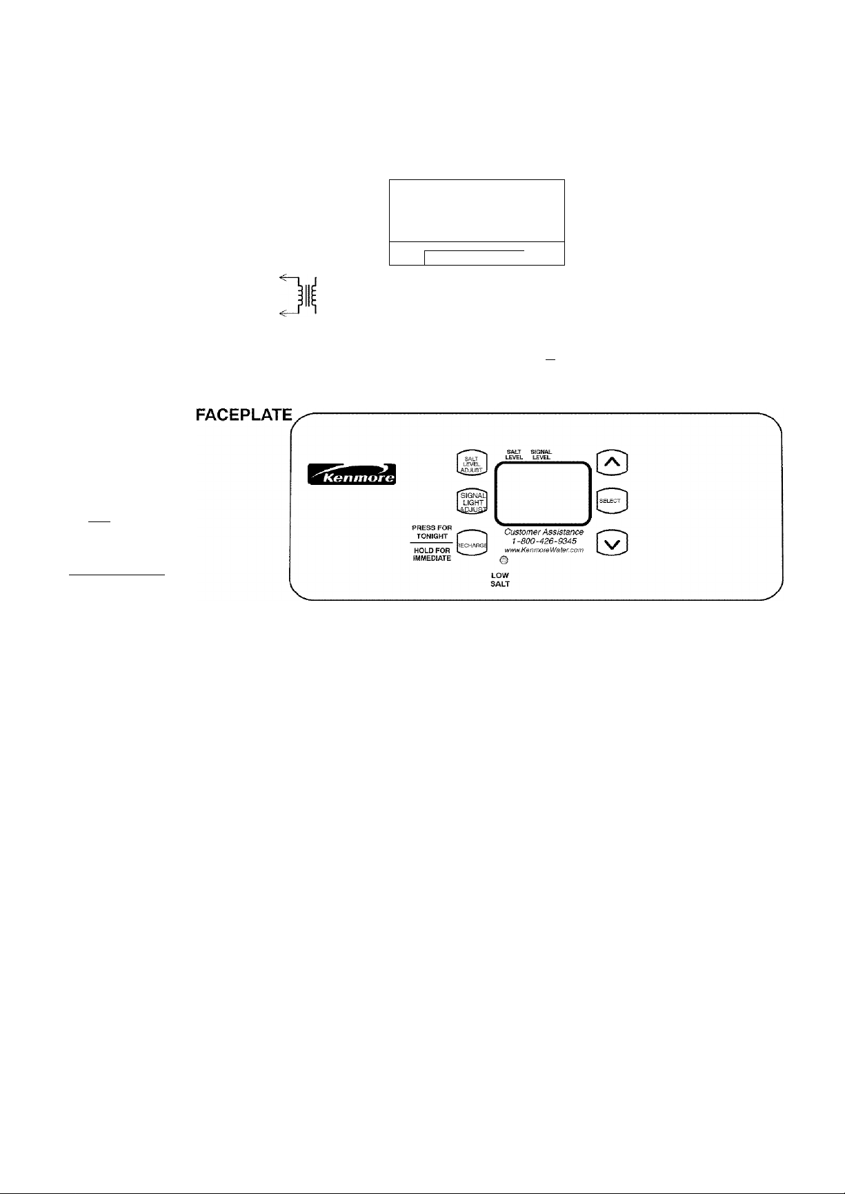
WIRING SCHEMATIC BACK OF TIMER
AC INPUT PCS- ' TURBINE MOTOR
24VAC
Transformer
Turbine
Sensor
TO
_
GNC|-'
+5
(PWA)
1
-----------
1
valve
motor
n
grn
NO Position
a Switch
NO
Keep this manual with your water softener. If repairs are needed, the service technician must have
the information on the following 8 pages. For telephone assistance, call toll free, 1-800-426-9345.
ALWAYS MAKE THESE INITIAL CHECKS FIRST
Does the time display show the correct time of
day?
- - If display is blank, check power source to the
softener.
--If time is flashing, power was off for over 6
hours. The softener resumes normal operation
but regenerations occur at the wrong time.
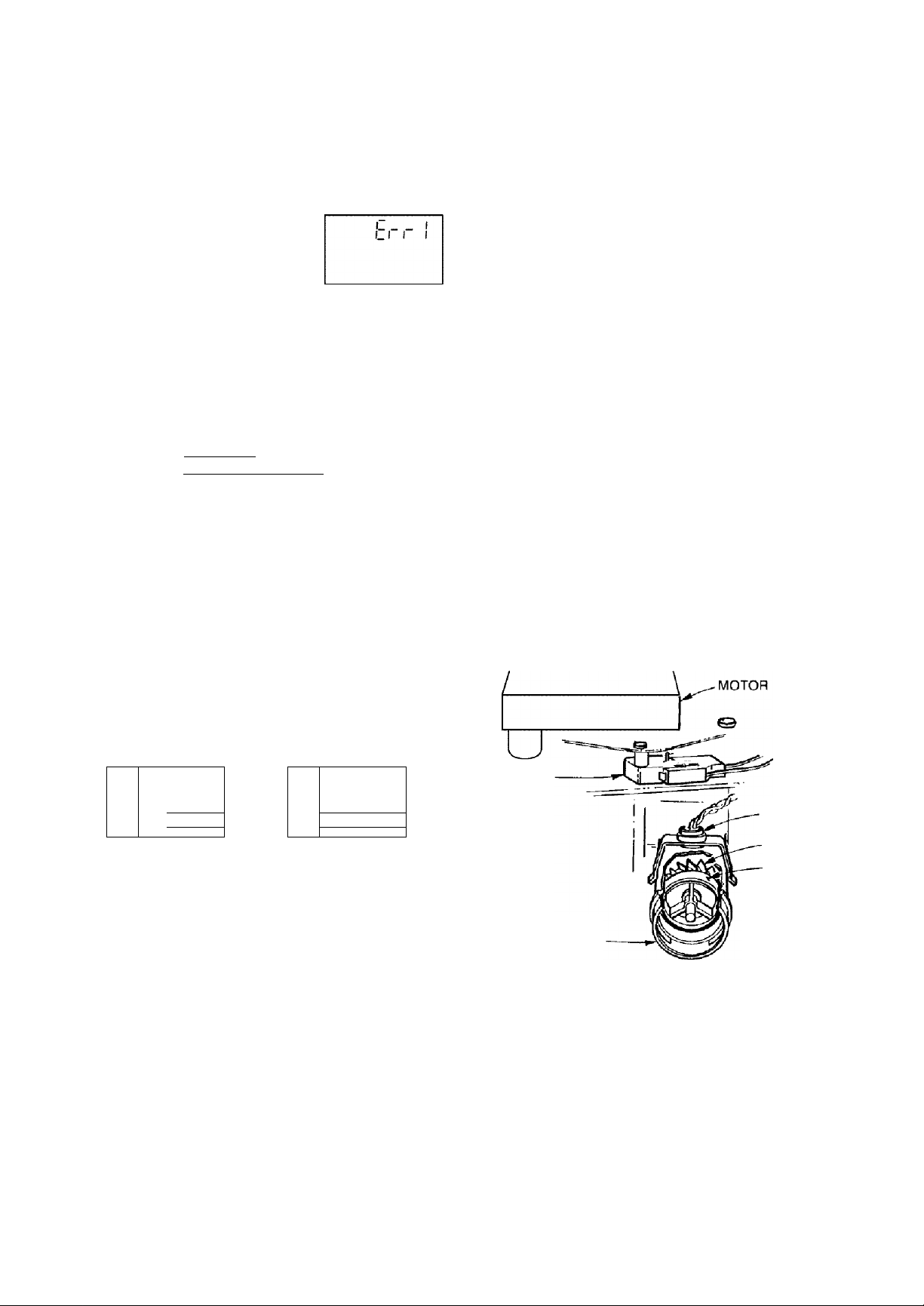
- - If an error code (Example: Err3) shows in the
faceplate display, go to AUTOMATIC ELEC
TRONIC DIAGNOSTICS, page 5-2.
Plumbing bypass valve(s) must be fully in ser
vice position.
The inlet and outlet pipes must connect to the
softener inlet and outlet respectively.
Is the transformer plugged into a "live",
grounded wall outlet, and the power cable fas
tened securely to the controller?
The valve drain hose must be free of kinks and
sharp bends, and not elevated over 8 ft. above the
floor.
Is there salt in the storage tank?
Is the brine tubing connected? Brine tubing con
I
nects to nozzle venturi and brine valve assembly.
(See page 6-3)
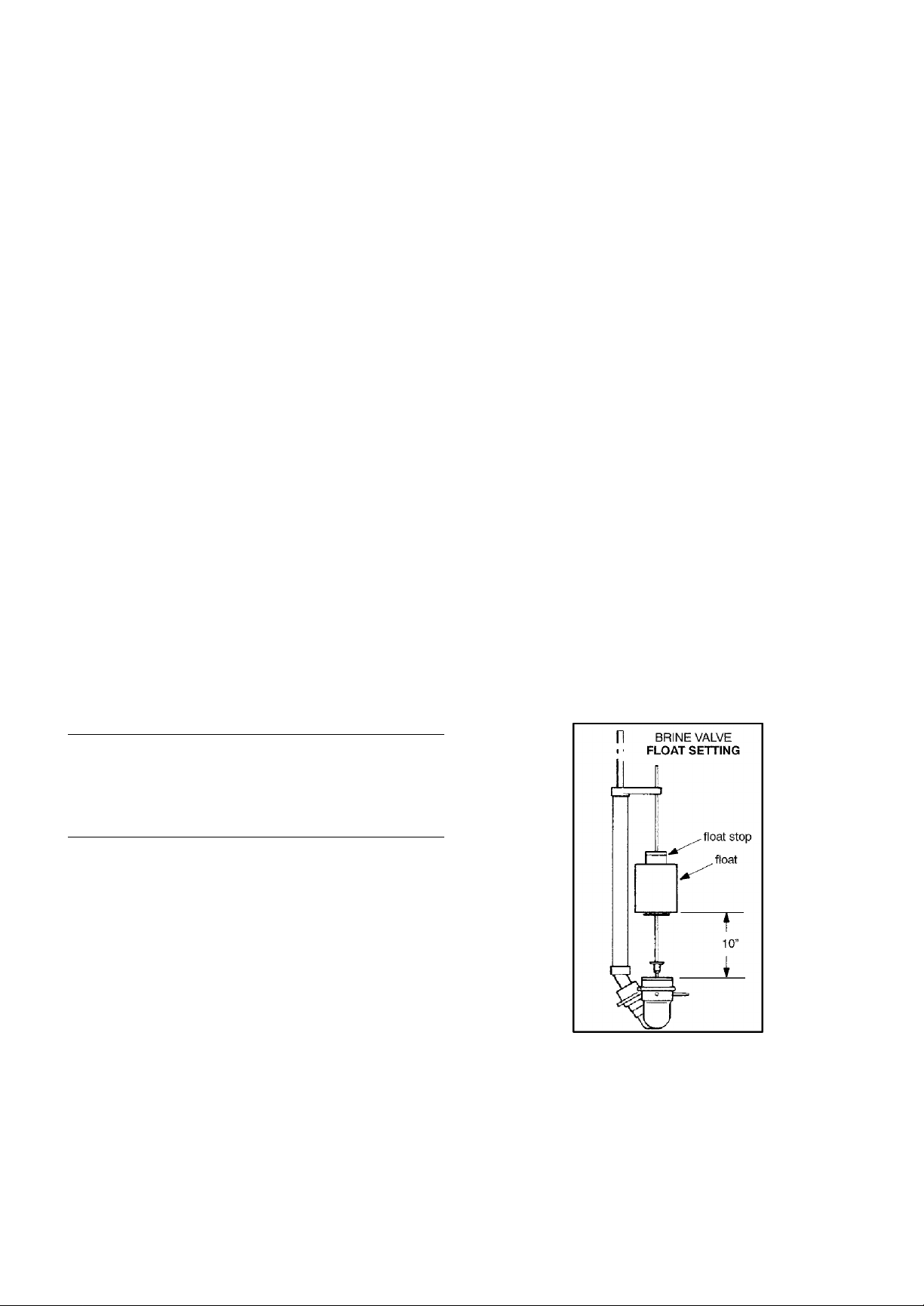
Is the brine valve float set right? (See page 5-4).
Press the SELECT button two times to display
I
the hardness setting. Be sure it is the correct set
ting for the household's water supply. (Make a
hardness test of the raw water and compare with
the hardness setting. Also test a soft water sam
ple to verify if a problem exists.) Press the SE
LECT button twice more to return to present time
in the display.
If you do not find the problem after making initial
checks, do the MANUAL INITIATED ELEC
TRONIC DIAGNOSTICS, and the MANUAL AD
VANCE REGENERATION CHECK.
5 - 1
Problems, Questions? Call 1-800-426-9345 Kenmore Water Line
Page 23
SECTION 5
SERVICE TECH. INFORMATION
A. TROUBLESHOOTING
AUTOMATIC ELECTRONIC DIAGNOSTICS
The faceplate timer (PWA) com
The chart below shows the error codes that could
appear, and the possible defects for each code.
puter has a self-diagnostic func
tion for the electrical system, ex
cept for input power and water
meter. The computer monitors electronic compo
nents and circuits for correct operation. If a malfunc
tion occurs, an error code appears in the faceplate
display.
CODE
Erri, ЕггЗ,
Err4
Errs
PROCEDURE FOR REMOVING ERROR CODE FROM FACEPLATE: 1. Unplug transformer from outlet 2. Correct
defect 3. Plug in transformer 4. Wait for 8 minutes. The error code will return if the defect was not corrected.
MOST LIKELY LESS LIKELY
motor inoperative / wiring harness or connection to switch / position switch / valve defect causing
high torque_________________________________________________________________________
faceplate timer (PWA)
MANUAL INITIATED ELECTRONICS DIAGNOSTICS
To enter diagnostics, press the SELECT button
and hold for three seconds.
While an error code appears in the display, all face
plate buttons are inoperable except the SELECT but
ton. SELECT remains operational so the service per
son can make the MANUAL INITIATED ELEC
TRONIC DIAGNOSTICS (below) to further isolate
the defect, and check the water meter.
POSSIBLE DEFECT
Pass a small magnet back and forth in front of the
sensor. You should get a reading in the display. If
you get a reading, unhook the in and out plumbing
and check the turbine for binding.
You will see the following display, showing valve
cycle position, position switch status (open or
closed), and turbine operation.
valve position indicator
sOFF
position switch
indicator (open)
1 II II 1
LI ULL
Л
______
X
WATFR FLOW
turbine count (no
water flowing)
turbine count {water
flowing)
SOFF
4
gggg; _ ;
3
___
WATER FLOW
\ no
\
TURBINE OPERATION: If no water is flowing
through the softener, the turbine indicator displays
three zeros. When water is flowing, the flow bar
scrolls across the display, and a 000 to 199 count re
peats for each gallon of water passing through the
turbine. To check for positive operation of the tur
bine if zeros are shown, open a nearby soft water
faucet and observe the turbine count and flow bar.
If you don't get a reading in the display, with faucet
open, pull the sensor from the valve outlet port.
POSITION
SWITCH
SENSOR
___
VALVE
OUTLET
HOUSING
TURBINE
TURBINE
SUPPORT AND
SHAFT
POSITION SWITCH STATUS: With the valve in ser
vice, or any of the recharge cycles, the switch indica
tor will show open -*K-. While the valve is rotating
from one position to another, the indicator will
show the switch closed A defect is probable if
indications vary from this pattern.
5 - 2
Problems, Questions? Call 1-800-426-9345 Kenmore Water Line
Page 24
SECTION 5
SERVICE TECH. INFORMATION
A. TROUBLESHOOTING
VALVE POSITION INDICATORS: Depending on
the valve position, the following indicators show in
the display:
INDICATOR
Serv
...............
Fill
.............
Brine ...............
Bkwsh
Rinse
.............
..........................................
VALVE POSITION
service
fill
brining/brine rinse
backwash
fast rinse
When the valve is rotating from one cycle to another,
both indicators flash. For example, if the valve is in
transition between fill and brining, both Fill and
Brine flash. Upon reaching brining position. Fill
goes off and Brine is on steady. The time display
shows the minutes of the cycle remaining.
NOTE: If the faceplate is left in a diagnostic
display (or a flashing display when setting times
or hardness), present time automatically returns
if a button is not pressed within 4 minutes. To
return to the diagnositc display, repeat step 1.
OTHER INFORMATION: While in this diagnostic
screen, the following information is available and
may be beneficial for various reasons. This informa
tion is retained by the computer from the first time
electrical power is applied to the faceplate.
... Press Q to display the number of days this face
plate has had electrical power applied.
... Press to display the number of regenerations
initiated by this faceplate since the SR code number
was entered.
Press the RECFiARGE button to advance the
valve to each position and observe the switch
and position indicators to verify component op
eration, or to possibly isolate a defect.
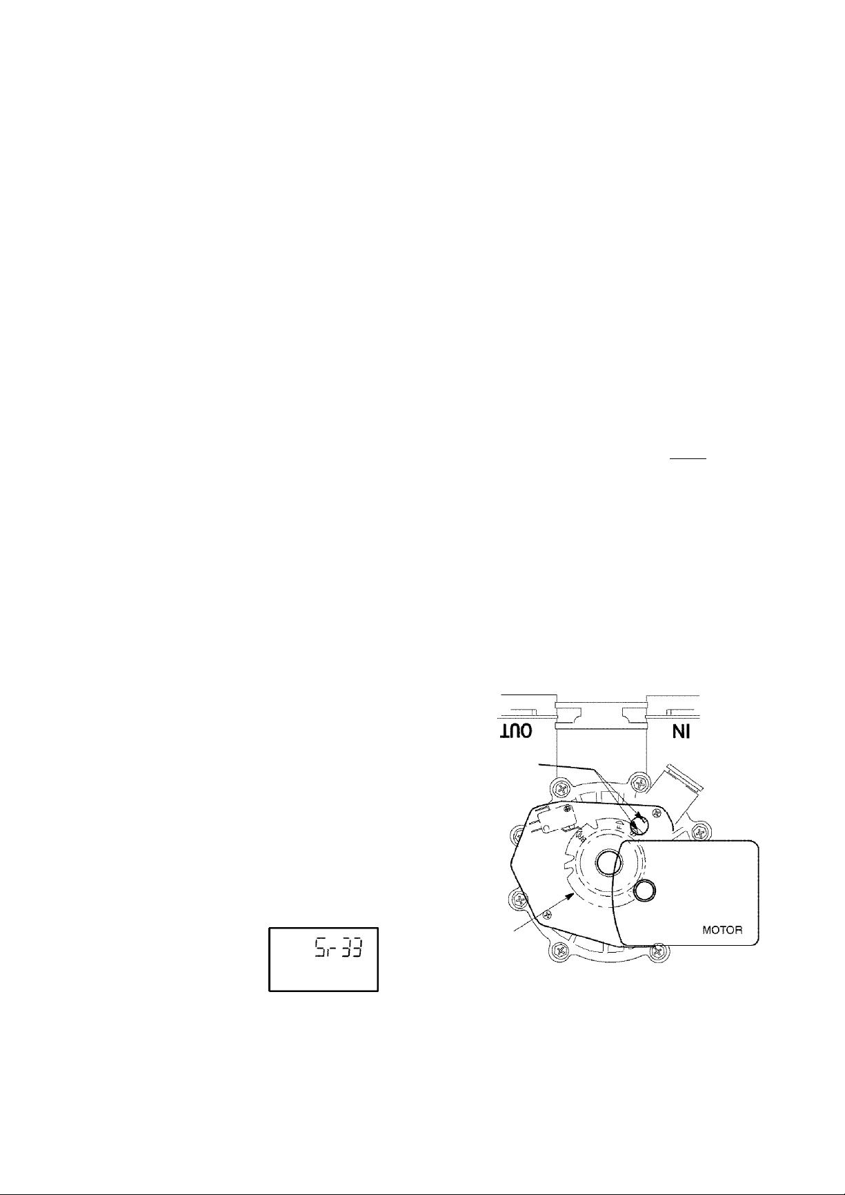
This code identifies the softener nominal capacity
size. If the wrong number shows, the softener will
operate on incorrect programming. Do the follow
ing as needed.
SR33 does show — Press the SELECT button to re
turn to the present time display.
To change SR number — Press the UP or DOWN
button until the correct SR code shows. Then, press
the SELECT button and reset the timer ... page 1-3.
TIMER PWA REPLACEMENT: Be sure the
valve is in service position when replacing the
timer PWA (observe valve cycle indicator).
If, after installing and programming the re
placement timer PWA, the valve is not in ser
vice position, do the following to assure correct
cycle orientation, or timing, between the face
plate and valve.
Use the MANUAL ADVANCE procedures,
page 5-4. With the RECHARGE NOW button,
advance through the recharge cycles until the
valve stops in service position, and RE
CHARGE no longer flashes in the display.
NOTE: The valve motor may automatically
drive through several valve positions while
searching for service. If an error code occurs,
unplug the transformer, then plug in again.
position
markers
(vaive in
service)
Press and hold the SELECT button for 3 seconds
until ...
.SR33 shows
Problems, Questions? Call 1-800-426-9345 Kenmore Water Line
CAM
5 - 3
Page 25
SECTION 5
SERVICE TECH. INFORMATION
A. TROUBLESHOOTING
MANUAL ADVANCE REGENERATION CHECK
This check verifies proper operation of the valve
motor, brine tank fill, brine draw, regeneration flow
rates, and other controller functions. Always make
the initial checks, and the mannal initiated diag
nostics.
Notes:
The faceplate display must show a steady time (not
flashing). If an error code shows, first press the SE
LECT button to enter the diagnostic display.
Press the RECHARGE button and hold in for 3
seconds. ^RECHARGE and Fill begin to flash (or
clean backwash begins, if set) as the softener en
ters the fill cycle of regeneration. When FILL is on
steady, remove the brinewell cover and, using a
flashlight, observe fill water entering the tank.
=^Note:
If the CLEAN feature is set to ON, a cleaning back
wash {CLEAN and Bkwsh or Rinse flashes in the dis
play, along with the minutes of the clean cycle re
maining), precedes the recharge.
a. If water does not enter the tank, look for an ob
structed nozzle, venturi, fill flow plug, brine tubing,
or brine valve riser pipe.
CYCLE FLOW RATES (GALLONS PER MIN.)
FILL (flow to salt storage tank)
BRINING .22 (.83 liters)
BRINE RINSE
MAX. BACKWASH
MAX. FAST RINSE
/ (flow
> to
1 drain)
0.3 (1.1 liters)
15 ^ 5^
2.0 (7.6 liters)
2.0 (7.6 liters)
a. If the softener does not draw brine ...
...nozzle and/or venturi dirty or defective. See page
3-2
...nozzle and venturi not seated properly on gasket.
See page 3-2
...restricted drain (check drain fitting and hose).
...defective nozzle and venturi seal. See page 3-2
...other inner valve defect (rotor seal, rotor & disc,
wave washer, etc.).
Note: If water system pressure is low, an elevated
drain hose may cause back pressure, stopping brine
draw.
Again press RECHARGE to move the softener
into backwash. Look for a fast flow of water from
the drain hose.
a. An obstructed flow indicates a plugged top dis
tributor, backwash flow plug, or drain hose.
El Press RECHARGE to move the softener into fast
rinse. Again look for a fast drain flow. Allow the
softener to rinse for a few minutes to flush out
any brine that may remain in the resin tank from
the brining cycle test.
To return the softener to service, press RE
CHARGE.
After observing fill, press the RECHARGE but
ton to move the softener into brining. A slow
flow of water to the drain will begin. Verify brine
draw from the brine tank by shining a flashlight
into the brinewell and observing a noticeable
drop in the liquid level.
Note:
Be sure a salt bridge is not preventing water with
salt contact.
Problems, Questions? Call 1-800-426-9345 Kenmore Water Line
5 - 4
Page 26
SECTION 5
SERVICE TECH. INFORMATION
B. ROTARY VALVE SERVICE
Before working on the valve, turn off the water sup
ply and disconnect from electrical power. TO RE
LIEVE PRESSURE:
• 3 VALVE BYPASS: Close the inlet valve and open
a soft water faucet. Then close the outlet valve and
open the bypass valve.
• SEARS SPECIAL BYPASS: Slide the bypass valve
stem to bypass position. Loosen three hex head
screws toward the back side of the valve to allow
pressure water to bleed out. Catch water with a rag.
DISASSEMBLY
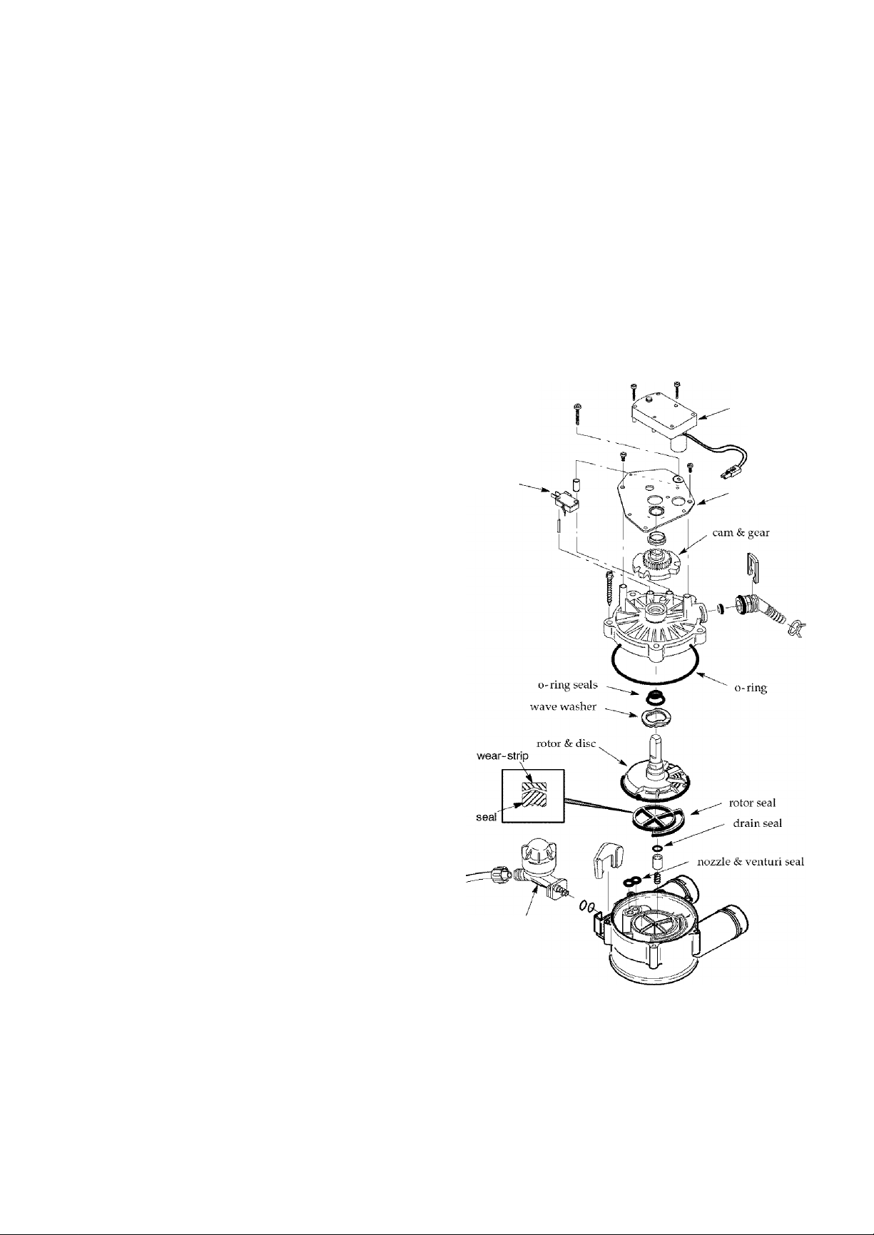
To remove a part or group of parts, refer to the valve
drawing. A common screwdriver or nut driver,
Phillips screwdriver and pliers are the only tools
needed to completely disassemble.
SERVICING THE VALVE
Inspect all o-rings, seals and gaskets for wear or de
fects.
Inspect the bottom surface of the rotor for scratches,
chips or wear.
Then, turn the rotor (clockwise only) to service posi
tion. Tighten the screws using a criss-cross pattern.
If a torque wrench is available, torque to 30-40 inch
pounds. Do not over tighten.
Lubricate the gear on the motor, and the valve cam
gear with Molykote grease, or other high quality
gear lubricant.
Be sure to orient switch as shown, with lever toward
the cam.
motor
switch-
motor plate
Note:
If replacement is needed, be sure to use the current
replacement part.
ASSEMBLY
Be sure all parts are in place and in the proper posi
tion. Lubricate ALL o-rings and seals with FDA ap
proved silicone grease. To install the rotor seal, first
place the seal into the valve groove, rounded side
down (see cross-section). Apply a light coating of
silicone grease to the seal's crossing ribs. Then, care
fully center the wear strip on the seal, and push it
downward onto the seal.
Install the nozzle and venturi seal and drain seal.
Assemble wave washer bearing, the wave washer,
and two o-rings onto the rotor top shaft. Then center
the rotor in the valve body, on the rotor seal.
Lower the cover onto the valve body and rotor shaft.
Then install the cover holding screws. Before tight
ening the screws, install the valve cam and gear.
see Nozzle
assembly
service,
page 3-2
5 - 5
Problems, Questions? Call 1-800-426-9345 Kenmore Water Line
Page 27
SECTION 5
SERVICE TECH. INFORMATION
C. WATER FLOW THROUGH THE SOFTENER VALVE
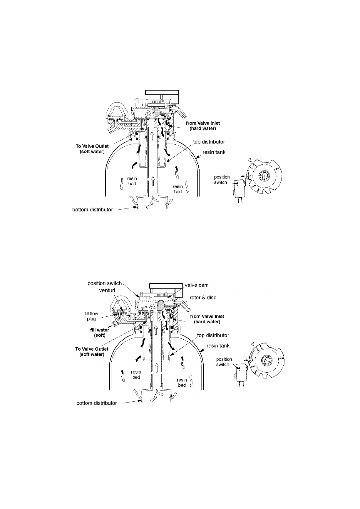
SERVICE CYCLE
Hard water enters the valve inlet port. Internal valve porting routes the
water down and out the top distributor, into the resin tank. Hard water is
softened as it passes through the resin bed, then enters the bottom
distributor. Soft water flows back into the valve and out the valve outlet, to
the house soft water pipes.
FILL CYCLE
To begin a regeneration, the electronic timer energizes the circuit to the valve
motor. The valve motor rotates the rotor and disc and the valve cam until the
position switch lever drops, to open the motor circuit and position the valve in
FILL. As the rotor and disc rotates, the port opens for SOFT water fill through
the venturi. Fill flow continues to the brine valve, and into the salt storage
tank. Soft water is still available to the house lines.
5 - 6
Problems, Questions? Call 1-800-426-9345 Kenmore Water Line
Page 28
SECTION 5
SERVICE TECH. INFORMATION
C. WATER FLOW THROUGH THE SOFTENER VALVE
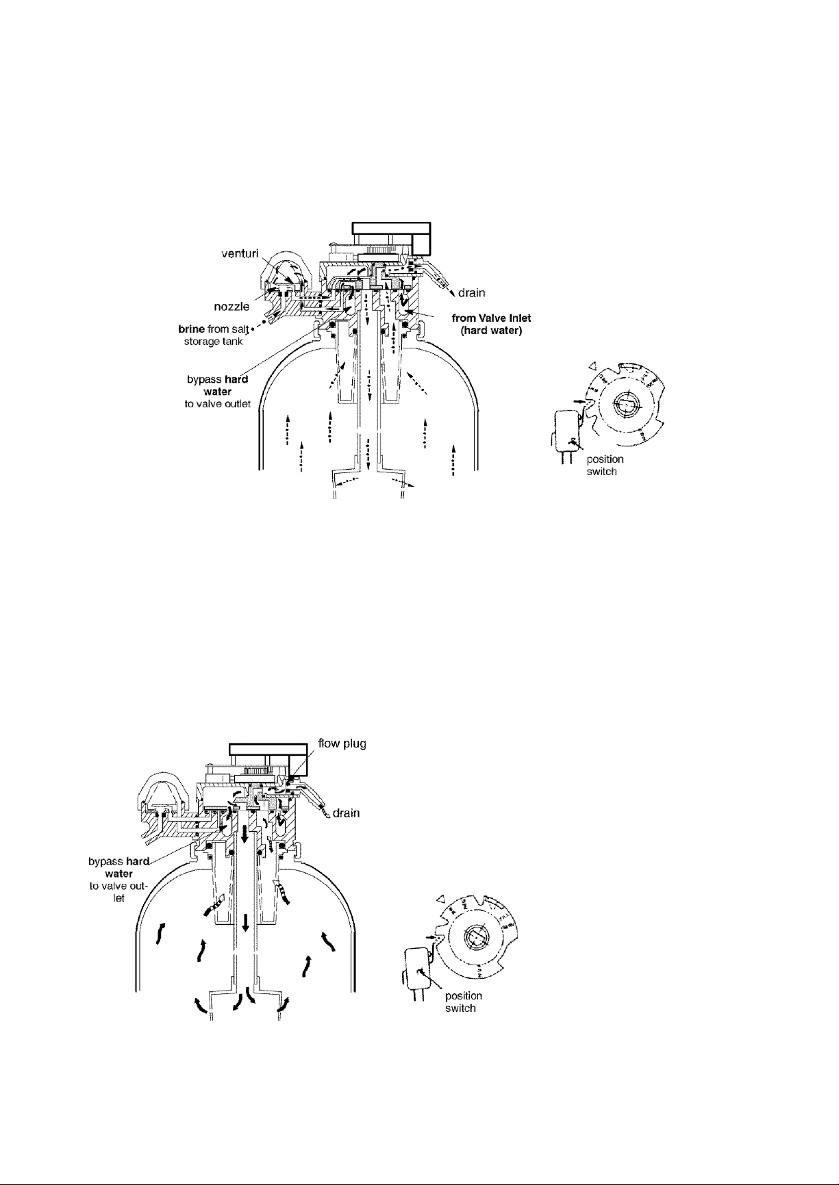
BRINING AND BRINE RINSE CYCLES
After fill, timer/switch action allows the motor to turn the rotor and disc into
BRINING position. Water flow is directed to the nozzle. Suction, created by the
nozzle and venturi, draws brine from the salt storage tank and injects it into the
resin bed via the bottom distributor. Flow continues out the top distributor and to
the drain. Hard water is available at the valve outlet.
When the brine valve closes to end brine draw, water flow continues in the same
directions to slowly RINSE brine from the resin bed and to the drain.
BACKWASH CYCLE
Timer/switch action again allows the motor to turn
the rotor & disc to place the valve in BACKWASH,
stopping water flow to the nozzle. Water is routed
down and out the bottom distributor, up through the
bed, and out the top distributor to the drain. The fast
flow (controlled by a flow plug in the drain fitting)
flushes dirt, sediments, iron deposits, remaining brine
and hardness to the drain.
5 - 7
Problems, Questions? Call 1-800-426-9345 Kenmore Water Line
Page 29
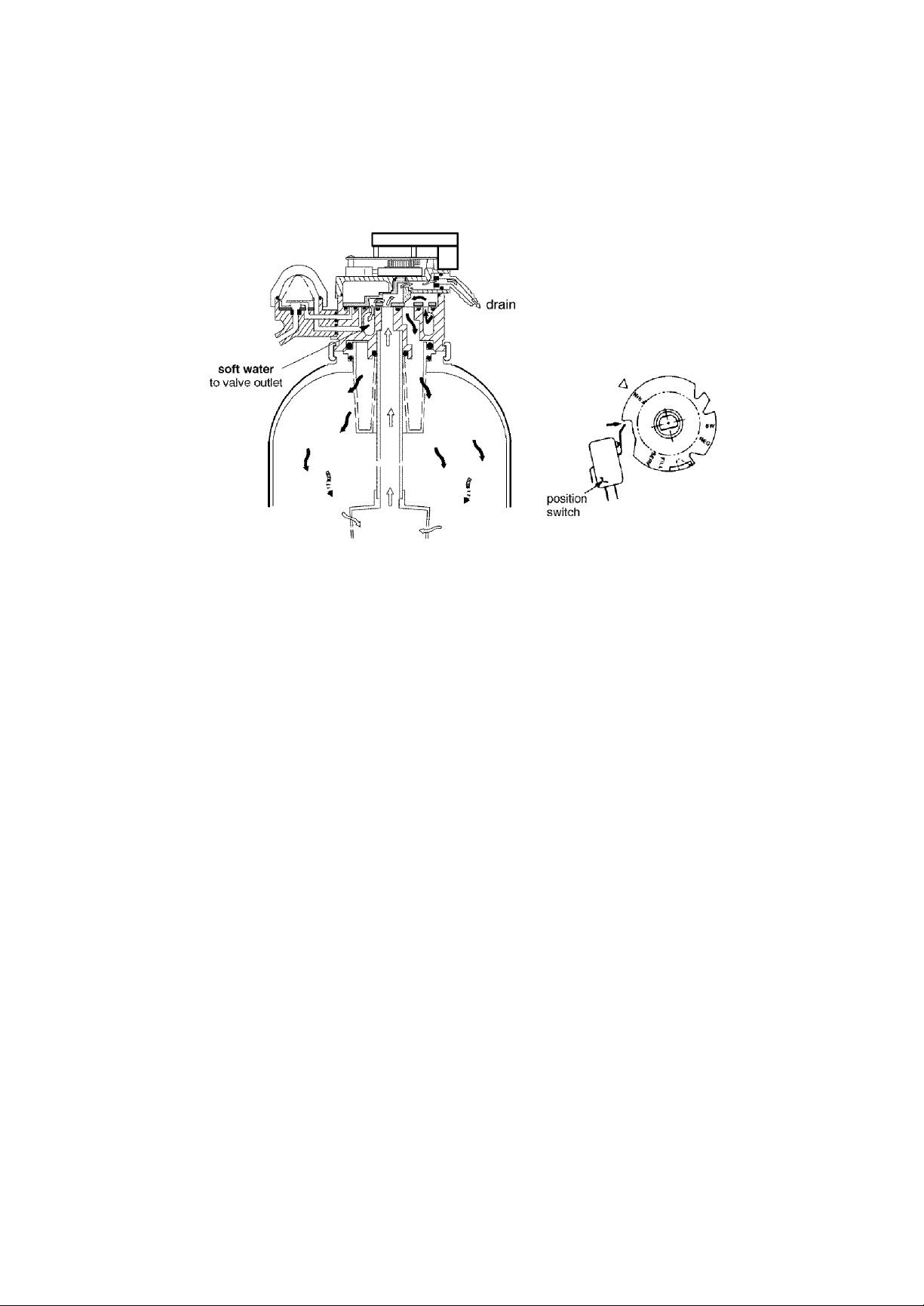
SECTION 5
SERVICE TECH. INFORMATION
C. WATER FLOW THROUGH THE 30FTENER VALVE
FAST RINSE CYCLE
During FAST RINSE, the rotor & disc is positioned so water flow enters the
resin tank through the top distributor, and exits through the bottom
distributor, to the drain.
The electronic timer again energizes the motor to return the valve to
service. As the valve rotates, the position switch lever drops to open the
circuit. The valve remains positioned in service until the electronic timer
initiates the next regeneration.
5 - 8
Problems, Questions? Call 1-800-426-9345 Kenmore Water Line
Page 30
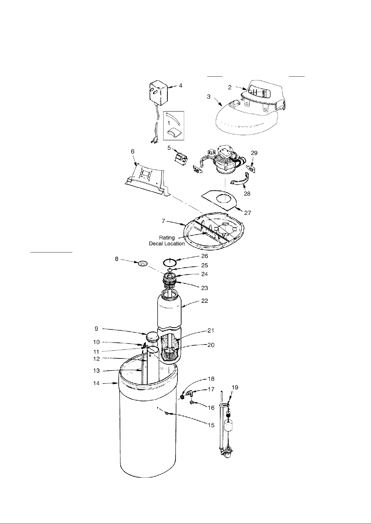
SECTION 6 I REPAIR PARTS FOR WATER SOFTENER
Kenmore MODEL NOS. 625.388270 03 and 625.388280 03
s
c
T
o
N
ij.jjjj.jj.jjjj.jj.jjjj
IJJJJJUJJJJJJJJJJJ
IJJ.^n»JJ J JJJJJ J J
ijjMS^^j j jjjjj j j
IJJ^^SJJ J JJJJJ j j
ijjjjjjjjjjjjjjjjj
rjJ^JJ^JJJJ^JJ^JJJJ^JJ^J
UJJJJJJJJJJJJJJJJ
6 - 1
Problems, Questions? Call 1-800-426-9345 Kenmore Water Line
Page 31
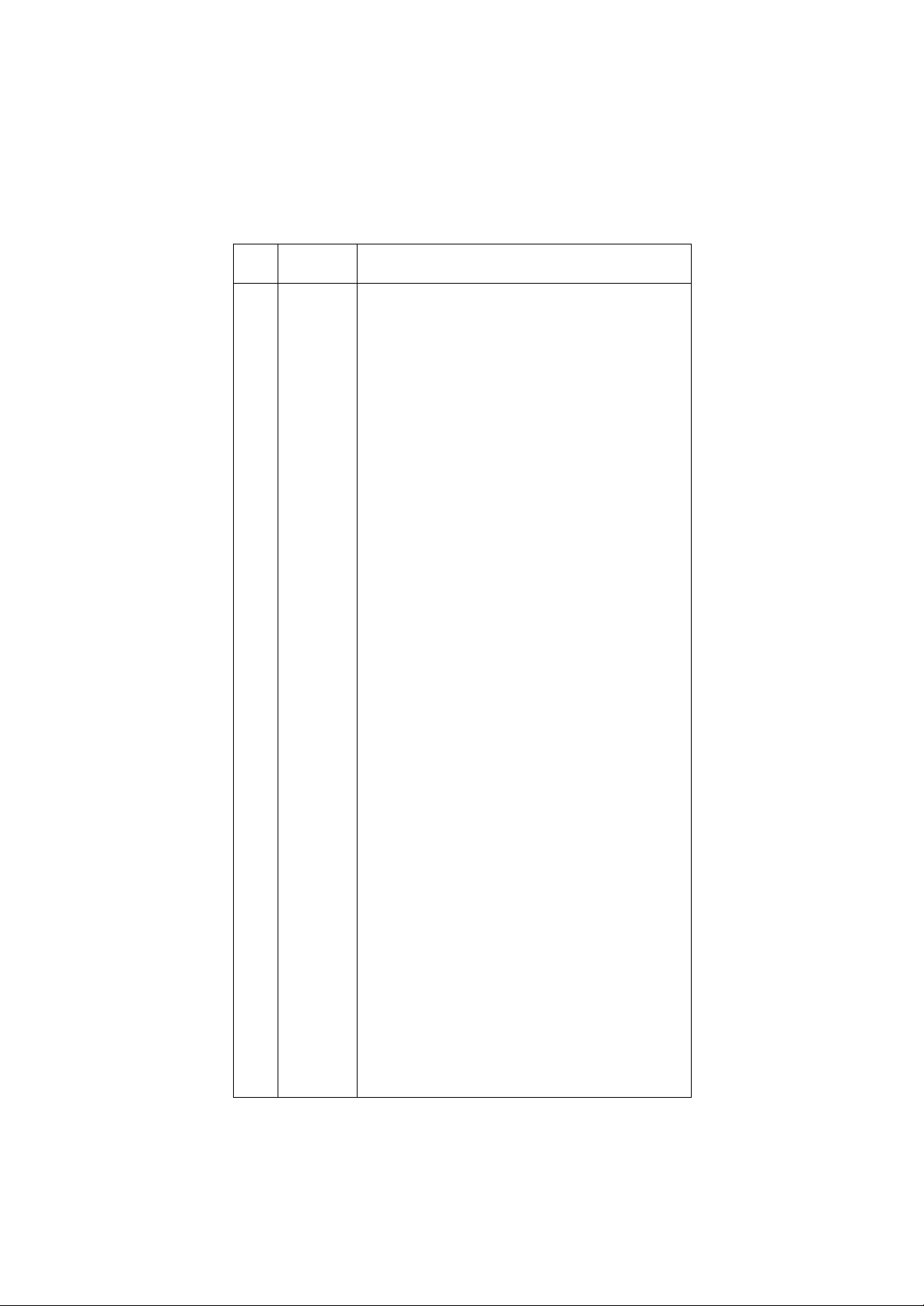
SECTION 6 I REPAIR PARTS FOR WATER SOFTENER
Kenmore MODEL NOS. 625.388270 03 and 625.388280 03
A. WATER SOFTENER COMPLETE
KEY
NO.
2
3 7229998
-
4 7252373 Transformer, 24V-1 OVA •
5 7268625 Timer Re pi. (PWA)
6
-
-
7 7231571 Rim
8 7265025
9 7219888 Brinewell Cover
10 7082150
11 7003847 0-Ring
12
13
14 7257307
15
16
17
18 9003500 Grommet •
19 7116488 Brine Valve Asm. (also see pages 6-3, 6-4)
20
21 0502272 Resin
22
23
24
25 7170254 0-Ring, 13/16" X 1-1/16"
26 7170296 0-Ring, 2-7/8" X 3-1/4"
28
29 7088033
♦
♦
♦
♦
PART
NUMBER
1
1
—
—
7230020
7264566 Instruction Decal
7230038
7268081 Faceplate Decal, UltraSoft 275
7264443 Faceplate Decal, UltraSoft 280
7100819 Brinewell
7137913
7232250
0900431
1103200
7105047 Replacement Distributor
7235478
7170270
7077870
7141001
7176292 Clamp Section (2 req.)
3442699
7144821
7258997 Installation Manual
7276547 Owners Manual
Cover Lock (req’d for ship, only)
Rinn Insert (req’d for shipping only)
Cover (main)
Salt Hole Cover (order following decal)
Faceplate (order following decal)
Ultra Cleansing Screen, UltraSoft 280 only
Wing Nut, 1/4"
Decal, Salt Level (0
Salt Storage Tank
Plastic Screw, 1/4" x 5/8"
Tube Clamp •
Tube Adaptor •
Resin Tank (incl. Key No. 21)
0-Ring, 2-3/4" x 3"
Top Distributor
Vapor Barrier
Clamp Retainer (2 req.)
Resin Bed Cleaner
Parts Bag, (includes parts marked with a *,
pages 6-2, 6-4 & 6-6) - order manuals
separtately if needed.
DESCRIPTION
♦ not illustrated.
(0 Aligns with top of brinewell.
• included in parts bag.
6 - 2
Problems, Questions? Call 1-800-426-9345 Kenmore Water Line
Page 32
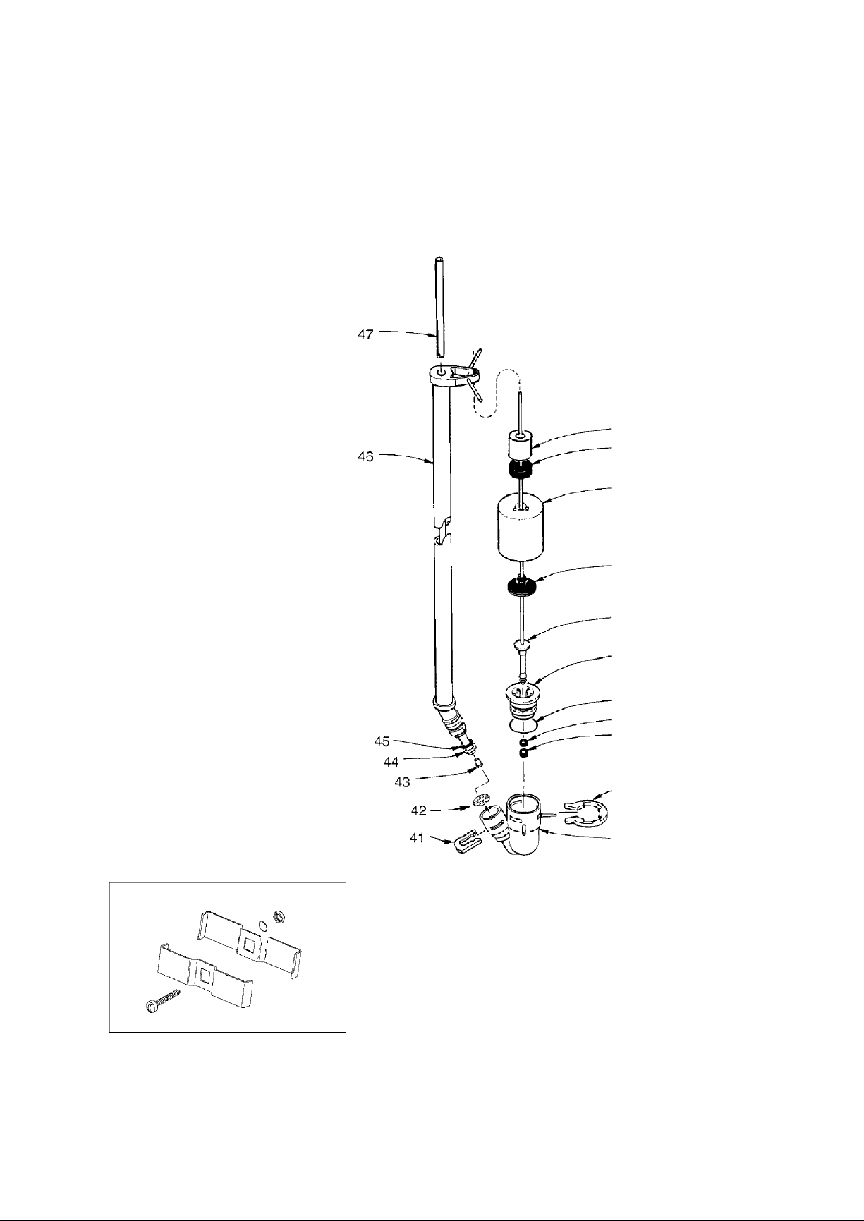
SECTION 6 I REPAIR PARTS FOR WATER SOFTENER
Kenmore MODEL NOS. 625.388270 03 and 625.388280 03
48
30
31
32
INLET - OUTLET
GROUNDING CLAMPS
33
34
35
36
37
38
39
40
,49
6 - 3
Problems, Questions? Call 1-800-426-9345 Kenmore Water Line
Page 33

SECTION 6 I REPAIR PARTS FOR WATER SOFTENER
Kenmore MODEL NOS. 625.388270 03 and 625.388280 03
g ggll^g /ASSEMBLY
KEY
NO.
30
31 0513860
32 7097202
33 0516947
34 7093216
35
36
37 0516211
38
39 1205500 Clip
40
41
42 7131365 Screen
43
44 7092294 Retaining Ring
45 7176161 0-Ring, 5/16x9/16
46
47 7113016 Tubing Assy, (includes Key Nos. 43, 44 & 45)
48 7171349
49 7248706 Grounding Kit •
PART
NUMBER
7168647
7092278 Guide Cap
7170288
0516924 Retainer, Bottom Seal
7092252
7080653 Clip
7094979 Insert
7095470 Brine Tube
Ceramic Weight
Float Stop
Float {includes Key No. 33)
Float Seal
Float Rod & Stem
0-Ring 15/16 X 1-3/16
Seal
Brine Valve Body
Oone Screen
DESCRIPTION
• included in parts bag, see page 6-2.
6 - 4
Problems, Questions? Call 1-800-426-9345 Kenmore Water Line
Page 34
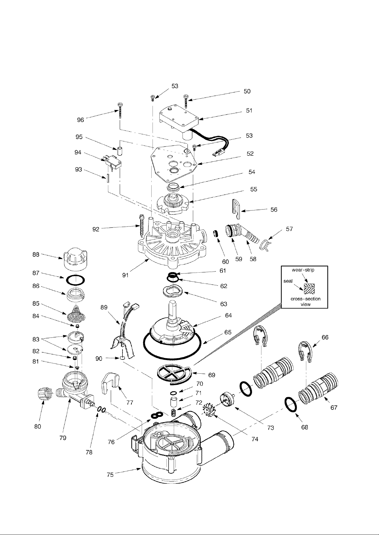
SECTION 6 I REPAIR PARTS FOR WATER SOFTENER
Kenmore MODEL NOS. 625.388270 03 and 625.388280 03
6 - 5
Problems, Questions? Call 1-800-426-9345 Kenmore Water Line
Page 35
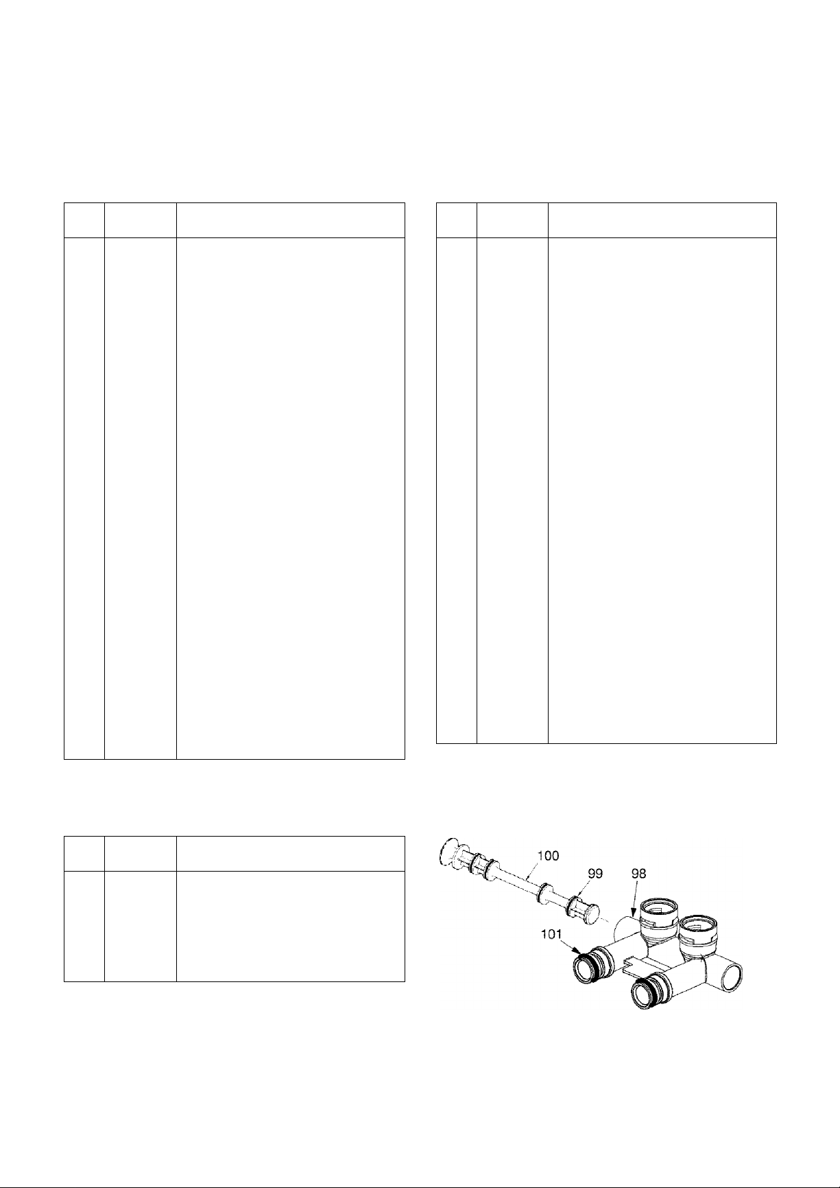
SECTION 6 I REPAIR PARTS FOR WATER SOFTENER
Kenmore MODEL NOS. 625.388270 03 and 625.388280 03
C. VALVE ASSEMBLY
KEY
NO.
50
51 7228544
52
53 0900857
54
55 7113927 Cam and Gear
56 7142942 Clip (Drain)
57 0900431 Tubing Clamp •
58 7024160
59
60 7092618 Flow Plug, 2.0
61
62 7170212 0-Ring, 3/4 X 15/16
63 7082087
64 7199232 Rotor & Disc
65 7170246
66
67 7278442 Installation Adaptor, 1 ” NPT
68 7170288
69
70
71 7092642
73
74
75 7082053
76
77
PART
NUMBER
7224087 Screw, #8-32 X 1” (2 req.)
Motor (incl. 2 ea. of Key No. 50)
7231385
0503288
7170327 0-Ring, 5/8 X 13/16
7170238 0-Ring, 7/16x5/8
7116713 Clip (2 req.) •
7134224 Rotor Seal
7170204 0-Ring, 3/8 X 9/16
7129889
2204101
7117858 Turbine
7081764 Seal (Nozzle & Venturi)
7081201
Motor Plate
Screw, #6-20 X 3/8 (2 req.)
Bearing
Drain Hose Adaptor
Wave Washer
0-Ring, 3-3/8 X 3-5/8
(2 req.) •
0-Ring (2 req.) •
Plug (Drain Seal)
Spring
Turbine Support and Shaft
Valve Body
Retainer (Nozzle & Venturi)
DESCRIPTION
KEY
NO.
78 7170319
79
80 1202600 Nut - Ferrule
81 7095030
82
83 7114533
- 7204362
84 7084607
85 7146043 Screen
86
87 7170262
88 7199729 Cap
89 7248714
90 0900060
91 7085263 Valve Cover
92 7074123 Screw, #10-14 X 2 (5 req.)
93
94 7030713 Switch
95 7117816 Spacer
96 7070412
♦
♦
♦
♦
♦
♦
♦ not illustrated
• included in parts bag, see page 6-2.
PART
NUMBER
0-Ring, 1/4 X 3/8 (2 req.)
7081104 Nozzle & Venturi Housing
Cone Screen
1148800
7167659 Screen Support
7077472 Expansion Pin
7253808
7129716
42-3433 Drain Tubing, 3/8" I.D. x 20'
42 -34401
42 -34403
7123613
Flow Plug, .3 gpm
Nozzle & Venturi Gasket Kit
Gasket (only)
Flow Plug, .15 gpm
0-Ring, 1-1/8 X 1-3/8
Wire Harness (Sensor)
0-Ring
Screw, #4-24 X 1 -1/8 (flat head)
Nozzle & Venturi Asm
(incl. Key Nos. 79 & 81 - 88)
Seal Kit (incl. Key Nos. 61,62, 65,
69, 70 & 76)
Flexible Connectors, 3/4”
Flexible Connectors, 1 ”
Silicone Grease (for 0-Rings)
DESCRIPTION
BYPASS INSTALLATION VALVE
KEY
NO.
97 0502206 Retainer Ring
98
99
100 7130911
101 7170288
♦ 7278434
PART
NUMBER
7271262
7105013 0-Ring, 13/16x1 (4 req.)
Bypass Body
Stem
0-Ring, 15/16x1 -3/16 (2 req.)
Bypass Valve (Complete) •
DESCRIPTION
Problems, Questions? Call 1-800-426-9345 Kenmore Water Line
97
6 - 6
Page 36

OWNER’S
MANUAL
MODEL NOS.
KGnmore
Water Softeners
UltraSoft 275
625.388270 03 UltraSoft 280
625.388280 03
The model number of
your water softener is
found on the rating decal.
This decal is on the rim,
under the salt cover.
When requesting service
or ordering parts, always
provide the following in
formation:
Get it fixed, at ydu r hdrrie dr ou ré!
Your Home
For repair-in your home-of all major brand appliances,
lawn and ga'-dsn equipment, cr heating and cooling systems,
no matter who made it, no matter who sold it!
For the replacement parts., accessories, and
owner's manuals that you neecf to do-it-yourself.
For Sears professional installation of home applances
and items like garage door openers and water heatefs.
1-800-4-MY-HOME- (i-800-469-4663)
Call anytime, day or night (U^S.A. and Canada)
ww-w.sesrs.com
Our Home
For repair of carry-tn items like vacuums, lawn equipment,
and electronics., call or go o.n-line for the location of your nearest
Sears Parts & Repair Center.
1-800-488-1222
Call a.nytime, day or n.ight (U.S.A. only)
www..sears.coin
TO' purchase a protection agreement (U.S..A.)
or maintenance agreement (Canada) on. a product serviced by Sears:
www.sears-ca
♦ Product Type
♦ Model Number
♦ Part Number
♦ Part Description
www.KenmoreWater.com
Sears, Roebuck and Co., Hoffman Estates, IL 60179 U.S.A.
1-800-827-6655 .JSA) 1-800-361-6665 (Canaoa)
Para pedir servicio de reparación
a domicilio, y para ordenar piezas.
1-888-SU-HOGAR ■
(1-888-784-6427)
i-'ey z\v r'Ü 1u»d6 r 41-
■ v.ir tur'de-IT-|T e tr
r 3’Jï-fi atl' SVI Le k-’.- f jfCtj'b "‘tftí.-fif- ìM'J'ru
' M.u t Ili 7,^ .Hj.
Him I* ‘^r-ciri'-r-r tir- -)- a-m t !
Ali Canada pouf service en français:
1-800-LE-FOYER"
{1-800-533-6937)
Wivw.sears.ca
è Sears, Roebuck and Co.
 Loading...