

Page 1

Installation Instructions
Instrucciones de instalación
Instructions pour l’installation
English / Español / Français
Kenmore
®
Top-Load Washer
Lavadora de Carga Superior
Laveuse à Chargement Superior
Table of Contents
WASHER SAFETY ......................................................................2
INSTALLATION REQUIREMENTS ...............................................2
Tools and Parts ..................................................................2
Location Requirements ......................................................3
Drain System .....................................................................4
Electrical Requirements ......................................................4
Índice
SEGURIDAD DE LA LAVADORA ................................................. 9
REQUISITOS DE INSTALACIÓN .................................................. 9
Herramientas y piezas ........................................................ 9
Requisitos de ubicación .................................................... 10
Sistema de desagüe .......................................................... 11
Requisitos eléctricos..........................................................11
INSTALLATION INSTRUCTIONS ................................................5
Connect Drain Hose ...........................................................6
Connect Inlet Hoses ...........................................................6
Level Washer ......................................................................7
Complete Installation Checklist .........................................8
INSTRUCCIONES DE INSTALACIÓN ......................................... 12
Conexión de la manguera de desagüe ............................. 13
Conexión de las mangueras de entrada ........................... 14
Nivelación de la lavadora ................................................ 15
Complete la instalación .................................................... 16
Table des matières
SÉCURITÉ DE LA LAVEUSE ....................................................... 17
EXIGENCES D’INSTALLATION .................................................. 17
Outillage et pièces .............................................................. 17
Exigences d’emplacement ..................................................18
Système de vidange ...........................................................19
Spécicationsélectriques .................................................... 19
INSTRUCTIONS D’INSTALLATION ............................................ 20
Raccordement du tuyau de vidange ................................... 21
Raccordement des tuyaux d’arrivée d’eau ......................... 22
Établissement de l’aplomb de la laveuse ........................... 23
Listedevéricationpourl’achèvement
de l’installation .......................................... Couverture arrière
P/N W10754825A
Sears Brands Management Corporation
Homan Estates, IL 60179 U.S.A.
www.kenmore.com
Sears Canada Inc.
Toronto, Ontario, Canada M5B 2C3
www.sears.ca
Page 2
WASHER SAFETY
INSTALLATION NOTES
Date of purchase: _________________________________________
Date of installation: _______________________________________
Installer: _________________________________________________
INSTALLATION REQUIREMENTS
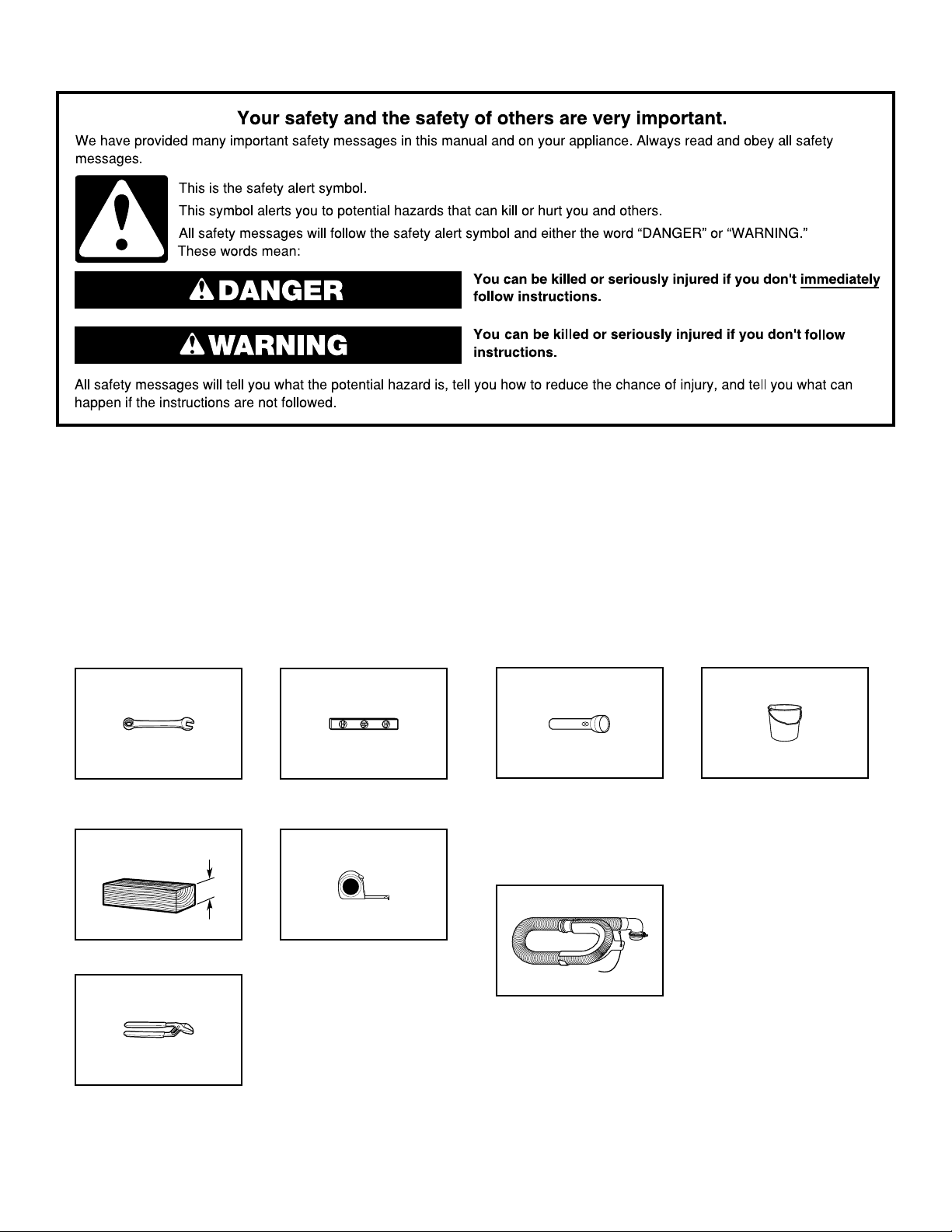
Tools and Parts
Gather required tools and parts before starting installation.
Tools needed:
Adjustable or open end
wrench 9/16" (14 mm)
4" min
(102 mm)
Level
Model number: ___________________________________________
Serial number: ____________________________________________
Optional tools:
Flashlight Bucket
Parts supplied:
NOTE: All parts supplied for installation are in
cardboard insert in the top of the washer.
Wood block
Pliers that open to
¾
" (44.5 mm)
1
2
Ruler or measuring tape
Drain hose with clamp,
U-form, and cable tie
Page 3
3"
(76 mm)
3"
(76 mm)
24 in.
2
(155 cm2)
48 in.
2
(310 cm2)
22"
(559 mm)
1"
(25 mm)
1"/0"*
(25 mm/0 mm)
5"
(126 mm)
14" max.
(356 mm)
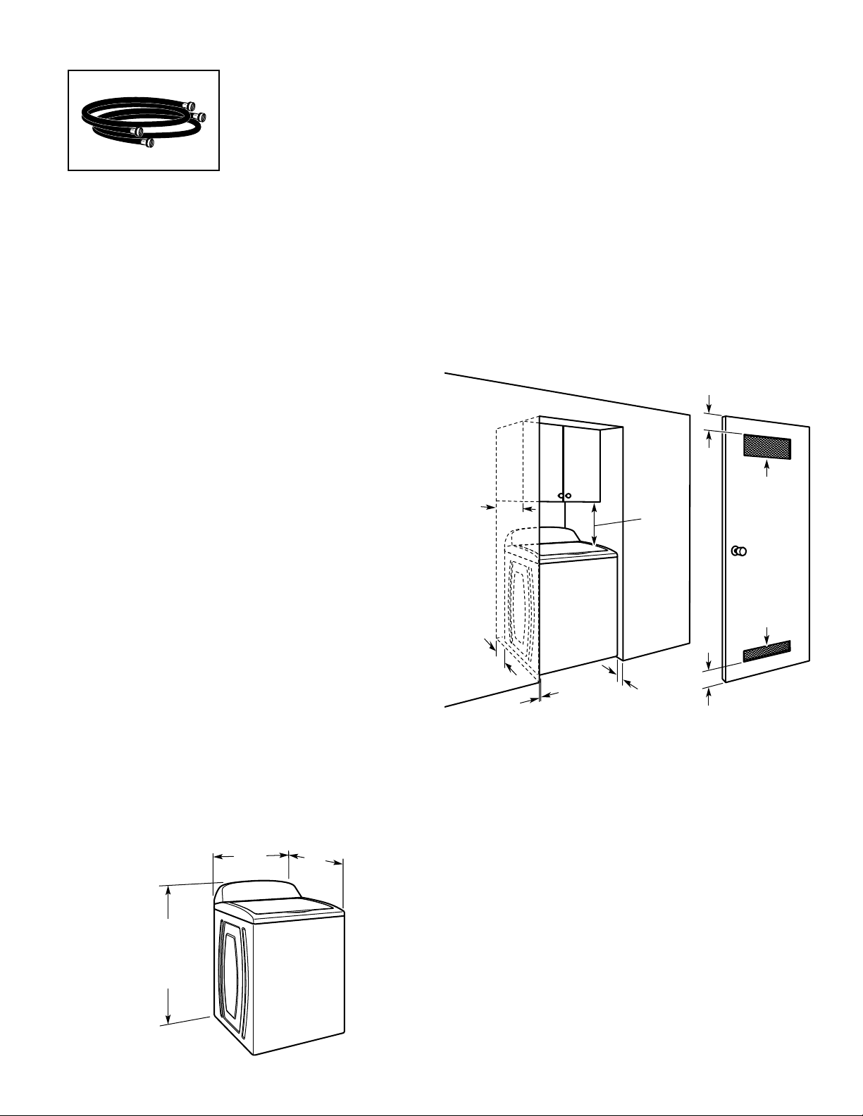
Parts needed: (Not supplied with washer)
Inlet hoses with
flat washers
To order, please refer to toll-free phone numbers on back page
of your Use and Care Guide.
n
8212656RP 10 ft. (3.0 m) Inlet hose, Black EPDM (2 pack)
n
8212641RP 5 ft. (1.5 m) Inlet hose, Black EPDM (2 pack)
n
8212546RP 4 ft. (1.2 m) Inlet hose, Black EPDM (2 pack)
n
8212545RP 5 ft. (1.5 m) Inlet hose, Red and Blue EPDM
(2 pack)
n
8212487RP 5 ft. (1.5 m) Nylon braided inlet hose (2 pack)
n
8212638RP 6 ft. (1.8 m) Nylon braided inlet hose, space
saving 90° elbow, hypro-blue steel couplings
(2 pack)
n
8212637RP 6 ft. (1.8 m) Inlet hose, Black EPDM, space
saving 90° elbow, hypro-blue steel couplings
(2 pack)
Alternate parts: (Not supplied with washer)
Your installation may require additional parts. To order,
please refer to toll-free numbers on back page of your
Use and Care Guide.
If you have: You will need:
Overhead sewer Standard 20 gal. (76 L) 39" (990 mm)
tall drain tub or utility sink, sump
pump and connectors (available from
local plumbing suppliers)
1" (25 mm) standpipe 2" (51 mm) diameter to 1" (25 mm)
diameter Standpipe Adapter
Part Number 3363920
Connector Kit Part Number 285835
Drain hose too short Extension Drain Hose Part
Number 285863
Connector Kit Part Number 285835
Lint clogged drain Drain Protector Part Number 367031
Connector Kit Part Number 285835
LOCATION REQUIREMENTS
Select proper location for your washer to improve performance
and minimize noise and possible “washer walk”. Install your
washer in a basement, laundry room, closet, or recessed area.
401/2"
(1029 mm)
437∕16"
without console
(1103 mm)
37"
(940 mm)
with console
1
/2"
29
(753 mm)
30"
(766 mm)
You will need:
n
A water heater set to 120° F (49° C).
n
A grounded electrical outlet located within 4 ft (1.2 m) of
power cord on back of washer.
n
Hot and cold water faucets located within 3 ft (0.9 m) of hot
and cold water ll valves on washer, and water pressure
of 20-100 psi (138-690 kPa).
n
A level oor with maximum slope of 1" (25 mm) under entire
washer. Installing on carpet is not recommended.
n
Floor must support washer’s total weight (with water and load)
of 315 lbs (143 kgs).
IMPORTANT: Do not install, store, or operate washer where it
will be exposed to weather or in temperatures below 32° F (0° C).
Water remaining in washer after use may cause damage in low
temperatures. See “Washer Care” in your Use and Care Guide
for winterizing information.
Proper installation is your responsibility.
Recessed area or closet installation
Dimensions show recommended spacing allowed, except for
closet door ventilation openings which are minimum required.
This washer has been tested for installation with spacing of
0" (0 mm) clearance on the sides. Consider allowing more space
for ease of installation and servicing, and spacing for companion
appliances and clearances for walls, doors, and oor moldings.
Add spacing of 1" (25 mm) on all sides of washer to reduce
noise transfer. If a closet door or louvered door is installed, top
and bottom air openings in door are required.
3
Page 4
DRAIN SYSTEM
4.5"
(114 mm)
Drain system can be installed using a oor drain, wall standpipe,
oor standpipe, or laundry tub. Select method you need.
Floor standpipe drain system
39"
4.5"
(114 mm)
Minimum diameter for a standpipe drain: 2" (51 mm). Minimum
carry-away capacity: 17 gal. (64 L) per minute. Top of standpipe
must be at least 39" (990 mm) high; install no higher than 96"
(2.44 m) from bottom of washer. If you must install higher than
96" (2.44 m), you will need a sump pump system.
(990 mm)
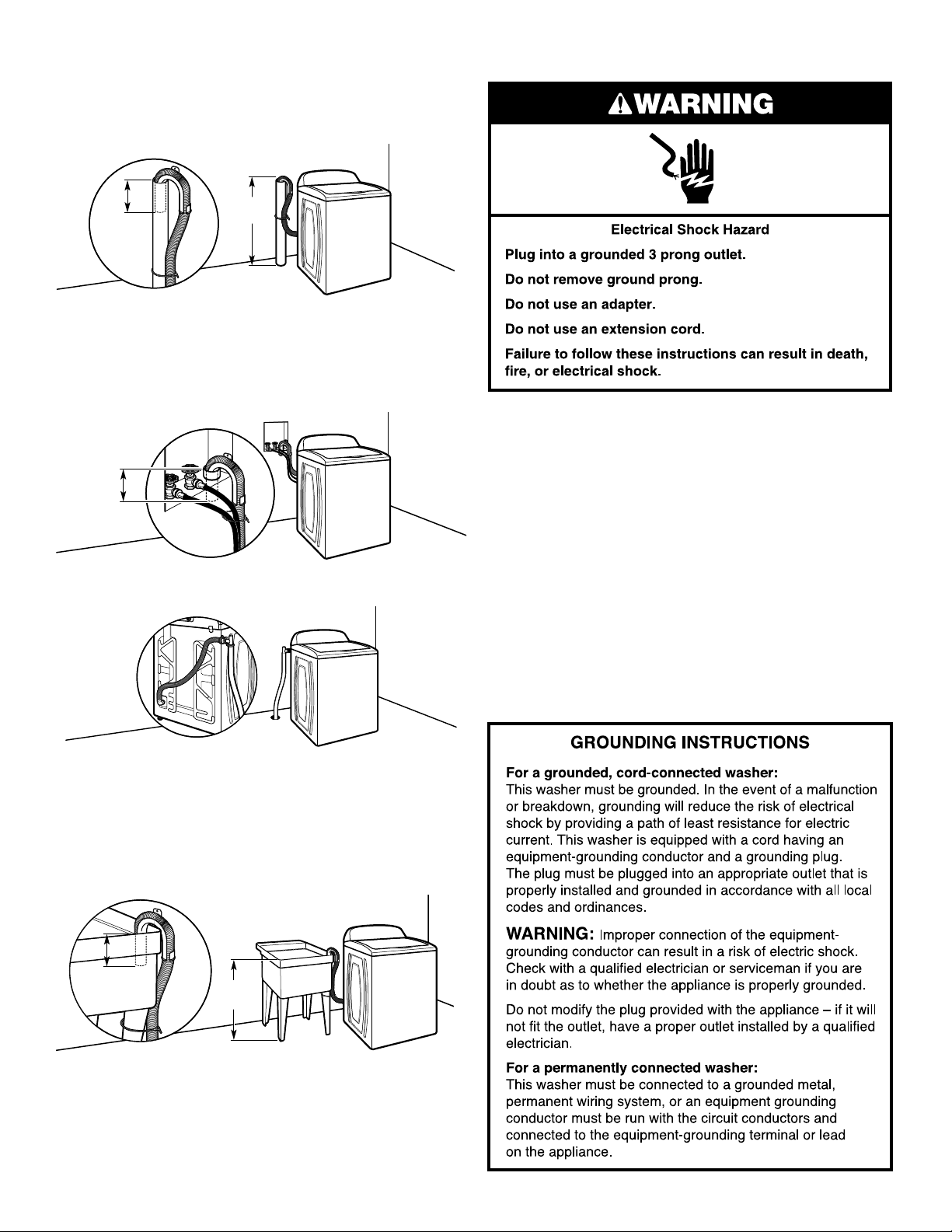
ELECTRICAL REQUIREMENTS
Wall standpipe drain system
4.5"
(114 mm)
See requirements for oor standpipe drain system.
Floor drain system
Floor drain system requires a Siphon Break Kit (Part Number
285834), 2 Connector Kits (Part Number 285835), and an
Extension Drain Hose (Part Number 285863) that may be
purchased separately. To order, please see toll-free phone
numbers in your Use and Care Guide. Minimum siphon break:
28" (710 mm) from bottom of washer. (Additional hoses may
be needed.)
Laundry tub drain system
n
A 120-volt, 60 Hz., AC only, 15- or 20-amp, fused electrical supply
is required. A time-delay fuse or circuit breaker is recommended.
It is recommended that a separate circuit breaker serving only this
appliance be provided.
n
This washer is equipped with a power supply cord having
a 3 prong grounding plug.
n
To minimize possible shock hazard, the cord must be plugged
into a mating, 3 prong, grounding-type outlet, grounded in
accordance with local codes and ordinances. If a mating outlet
is not available, it is the personal responsibility and obligation
of the customer to have the properly grounded outlet installed
by a qualied electrician.
n
If codes permit and a separate ground wire is used, it is
recommended that a qualied electrician determine that
the ground path is adequate.
n
Do not ground to a gas pipe.
n
Check with a qualied electrician if you are not sure the
washer is properly grounded.
n
Do not have a fuse in the neutral or ground circuit.
39"
(990 mm)
Minimum capacity: 20 gal. (76 L). Top of laundry tub must be at
least 39" (990 mm) above oor; install no higher than 96" (2.44 m)
from bottom of washer.
IMPORTANT: To avoid siphoning, no more than 4.5" (114 mm)
of drain hose should be inside standpipe or below the top of
wash tub. Secure drain hose with cable tie.
4
Page 5
INSTALLATION INSTRUCTIONS
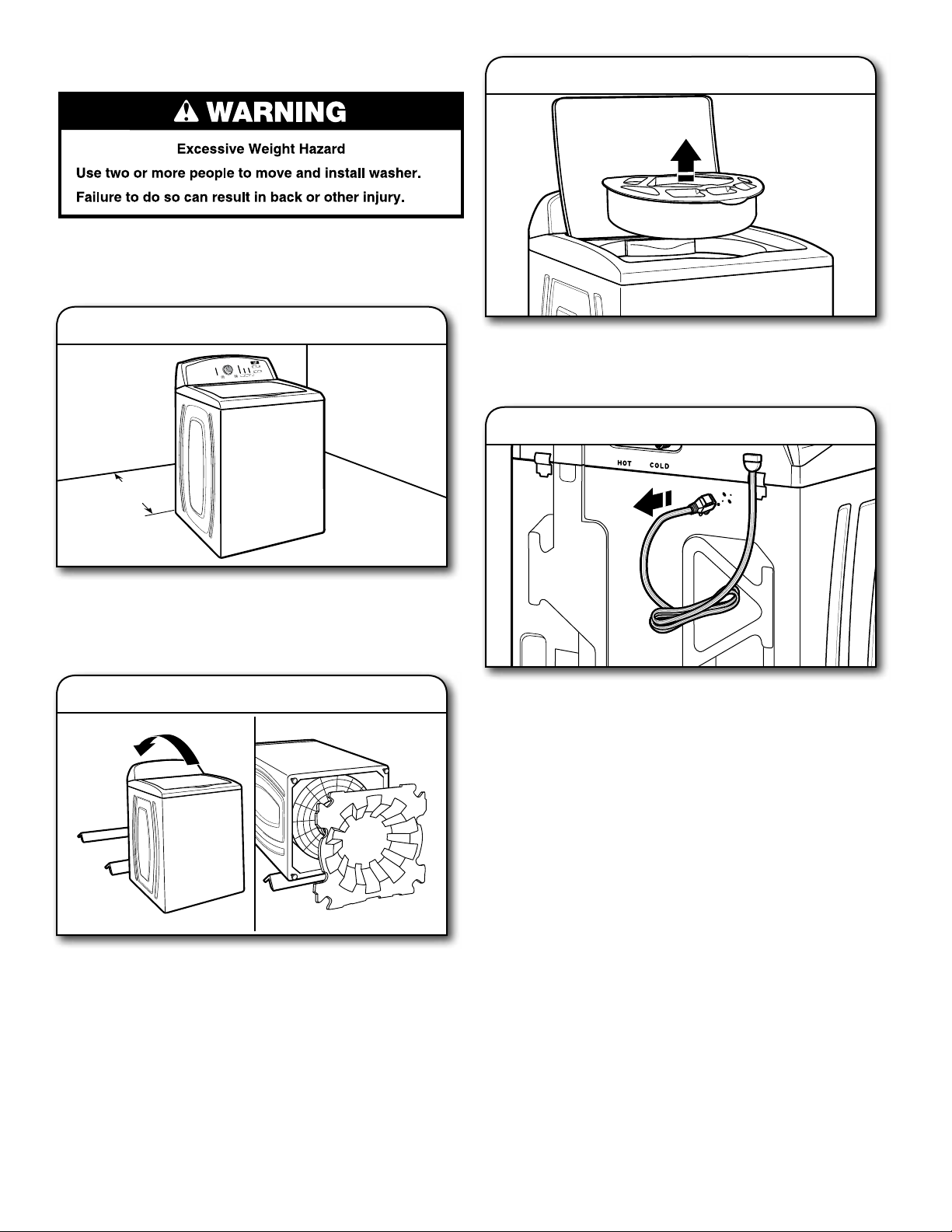
Before you start: remove shipping materials
It is necessary to remove all shipping materials for proper
operation and to avoid excessive noise from washer.
3. Remove packing tray from tub
1. Move washer
48"
(1.2 m)
Move washer to within 48" (1.2 m) of its nal location; it must
be in a fully upright position.
NOTE: To avoid oor damage, set washer onto cardboard
before moving it and make sure lid is taped shut.
2. Remove shipping base
Remove tape from washer lid, open lid, and remove cardboard
packing tray from tub. Be sure to remove all parts from tray.
NOTE: Keep tray in case you need to move washer later.
4. Free power cord
Firmly grasp power cord plug and pull to free from rear panel.
Gently place power cord over console to allow free access
to back of washer.
To avoid damaging oor, place cardboard supports from
shipping carton on oor behind washer. Tip washer back
and place on cardboard supports. Remove shipping base
by rotating base 90° to the right. Set washer upright.
IMPORTANT: Removing shipping base is necessary for proper
operation. If your washer includes a sound shield, please refer
to the instructions included with the sound shield to install it at
this time.
5
Page 6
CONNECT DRAIN HOSE
5. Attach drain hose to drain port
If clamp is not already in place on elbow end of drain hose,
slide it over end as shown. Squeeze clamp with pliers and
slide black elbow end of drain hose onto black drain port
and secure with clamp.
For a laundry tub or standpipe drain, go to step 6.
For a oor drain, remove the preinstalled drain hose form as
shown in Step 7. You may need additional parts with separate
directions. See “Tools and Parts”.
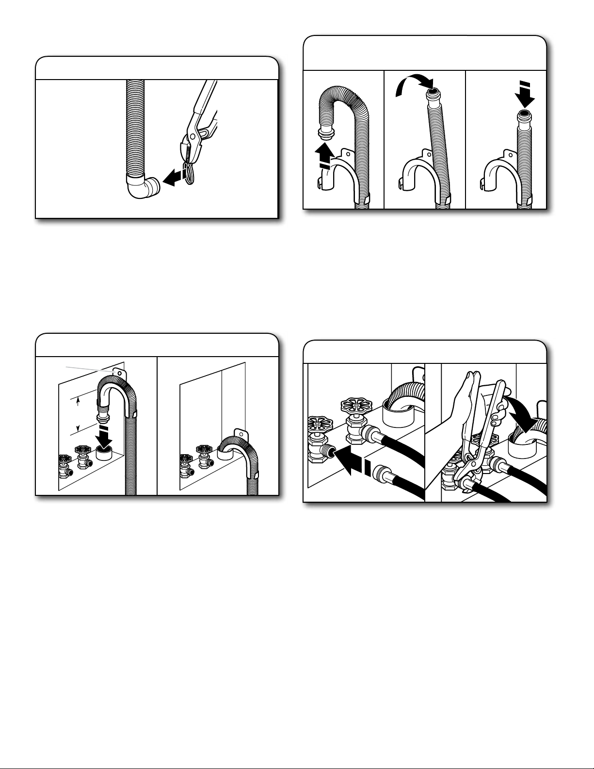
7. Remove drain hose form
(oor drain installations only)
For oor drain installations, you will need to remove the drain
hose form from the end of the drain hose. You may need
additional parts with separate directions. See “Tools and Parts”.
CONNECT INLET HOSES
Washer must be connected to water faucets with new inlet
hoses with at washers (not provided). Do not use old hoses.
NOTE: Both hoses must be attached and have water owing
to inlet valves. If you are only connecting to a cold water
faucet, you must use a Y-adapter (not provided).
6. Place drain hose in standpipe
Drain
hose form
4.5"
(114 mm)
Place hose into standpipe (shown in picture) or over side of
laundry tub.
IMPORTANT: 4.5" (114 mm) of drain hose should be inside
standpipe; do not force excess hose into standpipe or lay on
bottom of laundry tub. Drain hose form must be used.
8. Connect inlet hoses to water faucets
Verify location of hot and cold faucets. Attach hose to hot
water faucet. Screw on coupling by hand until it is seated on
washer. Use pliers to tighten couplings an additional twothirds turn. Repeat this step with second hose for cold water
faucet.
IMPORTANT: Do not overtighten or use tape or sealants on
valve when attaching to faucets or washer. Damage can result.
HELPFUL TIP: Make note of which hose is connected to hot
water to help in attaching hoses to washer correctly. In most
standard congurations, hoses will cross over each other
when attached correctly.
6
Page 7
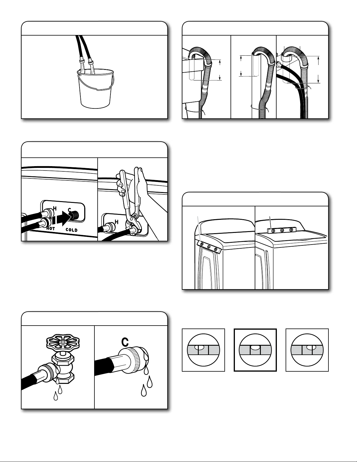
9. Clear water lines
12. Secure drain hose
Laundry Tub Standpipe Wall
Run water for a few seconds through hoses into a laundry tub,
drainpipe, or bucket to prevent clogs. Water should run until clear.
10. Connect inlet hoses to washer
4.5"
(114 mm)
Secure drain hose to laundry tub leg, drain standpipe, or inlet
hoses for wall standpipe with beaded tie strap.
It is the responsibility of the installer to install and secure the
drain hose into the provided plumbing/drain in a manner that
will avoid the drain hose coming out of or leaking from the
plumbing/drain.
4.5"
(114 mm)
4.5"
(114 mm)
LEVEL WASHER
IMPORTANT: Level washer properly to reduce excess noise
and vibration.
13. Check levelness of washer
Place level herePlace level here
Attach hot water hose to hot water inlet valve marked with a
red ring. Screw coupling by hand until it is snug. Use pliers to
tighten couplings an additional two-thirds turn. Repeat with
cold water inlet valve.
IMPORTANT: To reduce risk of hose failure, replace the hoses
every 5 years. Record hose installation or replacement dates
for future reference.
n
Periodically inspect and replace hoses if bulges, kinks, cuts,
wear, or leaks are found.
11. Check for leaks
Turn on water faucets to check for leaks. A small amount of
water may enter washer. It will drain later.
Move the washer to its nal location. Place a level on top
edges of washer. Use side seam as a guide to check levelness
of sides. Check levelness of front using lid, as shown. Rock
washer back and forth to make sure all four feet make solid
contact with oor. If washer is level, skip to step 15.
Not Level LEVEL Not Level
7
Page 8
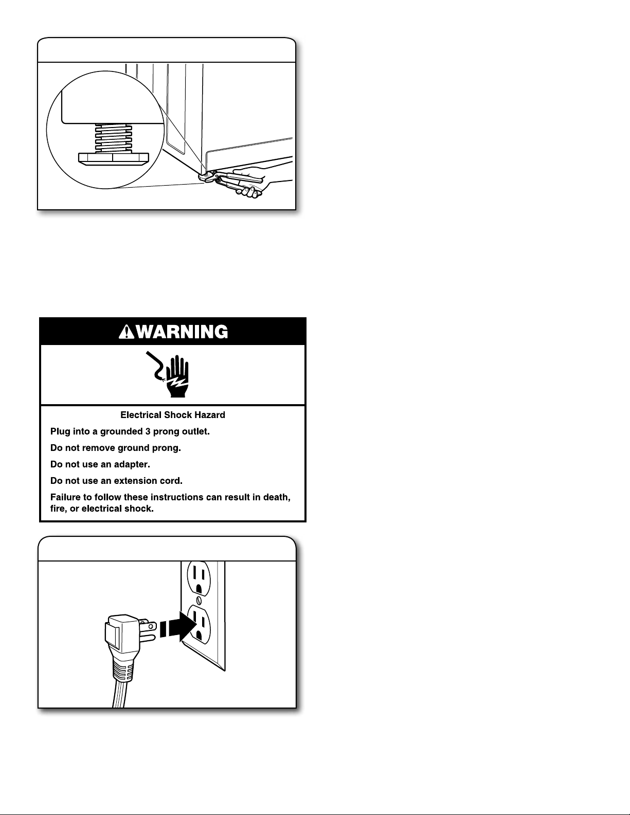
14.
If washer is not level:
Use adjustable pliers to turn the plastic leveling foot
counterclockwise to lower the washer or clockwise to raise the
washer. On all models, recheck levelness of washer and repeat
as needed.
HELPFUL TIP: You may want to prop up front of washer
about 4" (102 mm) with a wood block or similar object that
will support weight of washer.
Adjust leveling feet
Models with
metal feet
COMPLETE INSTALLATION
CHECKLIST
Check electrical requirements. Be sure you have correct
q
electrical supply and recommended grounding method.
Check that all parts are now installed. If there is an extra
q
part, go back through steps to see what was skipped.
Check that you have all of your tools.
q
Check that any shipping materials were completely
q
removed from washer.
Check that water faucets are on.
q
Check for leaks around faucets and inlet hoses.
q
Remove protective lm from console and any tape
q
remaining on washer.
Check that washer is plugged into a grounded
q
3 prong outlet.
Dispose of/recycle all packaging materials.
q
Read “Washer Care” in your Use and Care Guide.
q
To test and clean your washer, measure 1/2 of normal
q
recommended amount of powdered or liquid detergent
and pour it into washer basket or detergent dispenser
(on some models). Close lid. Select any cycle. Start washer
and allow to complete full cycle.
15. Plug into a grounded 3 prong outlet
8
Page 9

SEGURIDAD DE LA LAVADORA
NOTAS SOBRE LA INSTALACIÓN
Fecha de compra: _______________________________________
Fecha de instalación: ____________________________________
Instalador: ______________________________________________
REQUISITOS DE INSTALACIÓN
Herramientas y Piezas
Reúna las herramientas y piezas necesarias antes de comenzar
la instalación.
Herramientas necesarias:
Llave de tuercas
ajustable o de extremo
abierto de 9/16" (14 mm)
4" min
(102 mm)
Nivel
Número de modelo: ______________________________________
Número de serie:
_________________________________
Herramientas optativas:
Linterna Cubeta
Piezas suministradas:
NOTA: Todas la piezas suministradas para la instalación
están en una caja de cartón separada, en la parte superior
de la lavadora.
Bloque de madera
Pinzas que se abran a
1¾" (44,5 mm)
Regla o cinta para medir
Manguera de desagüe
con abrazadera, molde
en forma de U y atadura
para cables
9
Page 10

Piezas alternativas: (No se proveen con la lavadora)
Mangueras de entrada (2)
con arandelas planas (4)
Para hacer un pedido, consulte los números gratuitos
en la contraportada del Manual de uso y cuidado.
n
8212656RP Manguera de entrada de 10 pies (3,0 m) de
caucho de etileno propileno negro (EPDM)
(paquete de 2)
n
8212641RP Manguera de entrada de 5 pies (1,5 m) de
caucho de etileno propileno negro (EPDM)
(paquete de 2)
n
8212546RP Manguera de entrada de 4 pies (1,2 m) de
caucho de etileno propileno negro (EPDM)
(paquete de 2)
n
8212545RP Manguera de entrada de 5 pies (1,5 m) de
caucho de etileno propileno rojo y azul (EPDM)
(paquete de 2)
n
8212487RP Manguera de entrada de 5 pies (1,5 m) de
nylon trenzado (paquete de 2)
n
8212638RP Manguera de entrada de nylon trenzado de
6 pies (1,8 m), codo de 90° para ahorrar
espacio, acoplamientos de acero “hypro-blue”
(paquete de 2)
n
8212637RP Manguera de entrada de 6 pies (1,8 m) de
caucho de etileno propileno negro (EPDM),
codo de 90° para ahorrar espacio,
acoplamientos de acero “hypro-blue”
(paquete de 2)
Piezas alternativas: (No se proveen con la lavadora)
Su instalación puede requerir piezas suplementarias. Para hacer
un pedido, consulte los números gratuitos en la contraportada
del Manual de uso y cuidado.
Si tiene: Usted necesitará:
Una alcantarilla Tina de desagüe estándar de
suspendida 20 galones (76 L) 39" (990 mm) de
atura o lavadero utilitario, bomba de
sumidero y conectores (disponible con
proveedores locales)
Tubo vertical de Juego de adaptador de tubo vertical
1" (25 mm) de diámetro de 2" (51 mm) de diámetro a
1" (25 mm) de diámetro, pieza
número 3363920
Juego de conectores,
pieza número 285835
Una manguera de EJuego de extensión de desagüe,
desagüe corta pieza número 285863
Juego de conectores,
pieza número 285835
Desagüe obstruido Protector del desagüe,
por pelusa pieza número 367031
Juego de conectores,
pieza número 285835
REQUISITOS DE UBICACIÓN
1
/2"
Seleccione una ubicación
apropiada para su lavadora,
29
(753 mm)
para realzar el rendimiento y
reducir al mínimo el ruido y
la posible “caminata” de la
lavadora. Instale su lavadora
en un sótano, cuarto para
lavar, clóset o un lugar
401/2"
437∕16"
(1103
37"
mm)
empotrado.
Usted necesitará:
n
Un calentador de agua jado en 120°F (49°C).
n
Un contacto con conexión a tierra ubicado a no más
de 4 pies (1,2 m) del cable eléctrico en la parte posterior
de la lavadora.
n
Grifos de agua caliente y de agua fría ubicados a una
distancia de no más de 3 pies (0,9 m) de las válvulas
de llenado del agua caliente y fría en la lavadora y una
presión de agua de 20-100 lb/pulg² (138 – 690 kPa).
n
Un piso nivelado con un declive máximo de 1" (25 mm)
debajo de la lavadora completa. No se recomienda
la instalación sobre una alfombra.
n
El piso debe sostener el peso total de la lavadora (con
el agua y la carga) de 315 lb (143 kg).
IMPORTANTE: No instale, guarde ni utilice la lavadora
en donde estará expuesta a la intemperie o en temperaturas
por debajo de 32°F (0°C). El agua que queda en la lavadora
después del uso puede causar daños en temperaturas bajas.
Vea “Cuidado de la lavadora” enel Manual de uso y cuidado,
para saber cómo acondicionarla para el invierno.
La instalación correcta es su responsabilidad.
Instalación en zona empotrada o en el clóset
3"
(76 mm)
14" max.
(356 mm)
22"
(559 mm)
5"
(126 mm)
1"/0"*
(25 mm/0 mm)
1"
(25 mm)
3"
(76 mm)
30"
(766 mm)
2
48 in.
(310 cm2)
2
24 in.
(155 cm2)
10
Page 11

Las dimensiones muestran los espacios permitidos
4.5"
(114 mm)
recomendados, excepto por las aberturas de ventilación de la
puerta del clóset, las cuales son las mínimas necesarias. Esta
lavadora ha sido puesta a prueba para la instalación en espacios
de 0" (0 mm) en los costados. Considere dejar más espacio para
facilitar la instalación y el servicio técnico, así como espacio para
electrodomésticos que le acompañen y espacios libres para
las molduras de la pared, de la puerta y del piso. Agregue un
espacio adicional de 1" (25 mm) en todos los lados de la lavadora
para reducir la transferencia de ruido. Si se instala una puerta de
clóset o tipo persiana, es necesario que tenga aberturas para el
aire en la parte superior e inferior.
SISTEMA DE DESAGÜE
El sistema de desagüe de la lavadora se puede instalar utilizando
un desagüe de piso, un tubo vertical de pared, un tubo vertical
de piso o una tina de lavadero. Seleccione el método que
necesita.
Sistema de desagüe de tubo vertical de piso
39"
4.5"
(114 mm)
(990 mm)
Sistema de desagüe de tina de lavadero
39"
(990 mm)
Capacidad mínima: 20 gal. (76 L). La parte superior de la tina
de lavadero debe estar a 39" (991 mm) del piso como mínimo;
instálela a no más de 96" (2,4 m) de la base de la lavadora.
IMPORTANTE: Para evitar el efecto de sifón, no debe haber
más de 4,5" (114 mm) de manguera de desagüe dentro del
tubo vertical o debajo de la parte superior de la tina de lavado.
Siempre ajuste la manguera de desagüe con la altadura
para cables.
REQUISITOS ELÉCTRICOS
Diámetro mínimo para el desagüe de tubo vertical: 2" (51 mm)
Capacidad de desplazamiento mínima: 17 gal. (64 L) por minuto.
La parte superior del tubo vertical debe estar a 39" (991 mm) de
altura como mínimo; instálela a no más de 96" (2,4 m) de la base
de la lavadora. Si la instala a más de 96" (2,4 m), necesitará un
sistema de bomba de sumidero.
Sistema de desagüe de tubo vertical de pared
4.5"
(114 mm)
Vea los requisitos para el sistema de desagüe de tubo vertical
de piso.
Sistema de desagüe de piso
Un sistema de desagüe por el piso requiere de un juego
de desviación de sifón (pieza número 285834), 2 juegos de
conectores (pieza número 285385) y extensión de manguera de
desagüe (pieza número 285863), la cual puede comprarse por
separado. Para ordenar, sírvase consultar los números gratuitos
en el Manual de uso y cuidado. Desviación de sifón mínima:
28" (710 mm) de la base de la lavadora. (Se pueden necesitar
mangueras adicionales.)
n
Se necesita un suministro eléctrico de 120 voltios,
60 hertzios, CA solamente, de 15 ó 20 amperios
y protegido con fusible. Se recomienda un fusible
retardador o un cortacircuitos, en un circuito
independiente que preste servicio únicamente
a este aparato.
n
Esta lavadora viene equipada con un cable eléctrico
dotado de un enchufe de 3 terminales con conexión
a tierra.
n
Para reducir al mínimo el peligro de posibles choques
eléctricos, el cable debe ser enchufado en un contacto
apropiado de pared de 3 terminales, conectado a tierra
de acuerdo con los códigos y normas locales. Si no hay
disponible una salida equivalente, es responsabilidad
y obligación personal del cliente de tener un contacto
apropiado con conexión a tierra instalado por un
electricista calicado.
n
Si los códigos lo permiten y se emplea un alambre
de conexión a tierra separado, es recomendable que
un electricista calicado determine si la trayectoria
de conexión a tierra es adecuada.
n
Si no está seguro de que la conexión a tierra de la lavadora
sea la adecuada, verifíquela con un electricista competente.
11
Page 12

INSTRUCCIONES DE INSTALACIÓN
Antes de comenzar: Cómo quitar los materiales de transporte
Es necesario quitar todos materiales de transporte para
obtener un funcionamiento adecuado y para evitar ruido
excesivo de la lavadora.
1. Mueva la lavadora
48"
(1,2 m)
Mueva la lavadora a 4 pies (1.2 m) de su ubicación nal.
Debe estar en posición vertical.
NOTA: Para evitar daños en el piso, coloque la lavadora
sobre un cartón antes de moverla y asegúrese de que
la tapa esté cerrada con cinta adhesiva.
2. Saque la base de transporte
12
Para evitar dañar el piso, coloque los soportes de cartón de
la caja de embalaje sobre el piso detrás de la lavadora. Incline
hacia atrás la lavadora y colóquela sobre los soportes de
cartón. Quite la base de embalaje rotando la base 90° hacia
la derecha. Coloque la lavadora en posición vertical.
IMPORTANTE: Para un funcionamiento adecuado es
necesario quitar la base de transporte. Si su lavadora incluye
un aislador de sonido, consulte las instrucciones incluidas
con el mismo para instalarlo en este momento.
Page 13

3. Saque la bandeja de empaque
de la tina
Quite la cinta adhesiva de la tapa de la lavadora, abra la tapa y
saque la bandeja de empaque de cartón de la tina. Cerciórese
de sacar todas las piezas de la bandeja.
NOTA: Guarde la bandeja por si necesita mover la lavadora
más tarde.
4. Liberar el cable eléctrico
CONEXIÓN DE LA MANGUERA
DE DESAGÜE
5. Sujete la manguera de desagüe
al puerto de desagüe
Si la abrazadera no está en su lugar, sobre el extremo del
codo de la manguera de desagüe, deslícelo sobre el extremo
como se muestra. Apriete la abrazadera con unas pinzas y
deslice el extremo de la manguera de desagüe con el codo
negro sobre el puerto de desagüe negro. Asegúrelo con la
abrazadera.
Para una tina de lavandería o una tubería vertical, vaya
al paso 6.
Para un desagüe por el piso, quite el molde de la manguera
de desagüe instalado previamente, como se muestra en el
paso 7. Podría necesitar piezas adicionales con indicaciones
por separado. Vea “Piezas y herramientas”.
Sujete con rmeza el cable eléctrico y jálelo para liberarlo
por completo del panel posterior. Después coloque el cable
eléctrico con cuidado sobre la consola para permitir un
acceso sin obstrucciones a la parte posterior de la lavadora.
6. Coloque la manguera de desagüe en
el tubo vertical
Molde de la
Bride de retenue
manguera
pour tuyau
de desagüe
de vidange
4,5"
(114 mm)
Coloque la manguera dentro del tubo vertical (se muestra
en la ilustración) o sobre el lado de la tina de lavadero.
IMPORTANTE: No debe haber más de 4,5" (114 mm)
de manguera de desagüe dentro del tubo vertical; no fuerce
el exceso de la manguera dentro del tubo vertical, ni lo
coloque en el fondo de la tina de lavadero. El molde de la
manguera de desagüe debe usarse.
13
Page 14

7. Cómo quitar el molde de la manguera
de desagüe (instalaciones con
desagüe por el piso únicamente)
9. Despeje las líneas de agua
Deje correr agua por algunos segundos por las mangueras,
a una tina de lavadero, tubo de desagüe o cubeta para evitar
que se obstruya. El agua debe correr hasta que salga limpia.
Para las instalaciones con desagüe por el piso, necesitará
quitar el molde de la manguera de desagüe del extremo de
la misma. Puede ser que necesite piezas adicionales con
instrucciones por separado. Vea “Piezas y herramientas”.
CONEXIÓN DE LAS MANGUERAS
DE ENTRADA
La lavadora debe estar conectada a los grifos de agua
con mangueras de entrada nuevas y arandelas planas
(no provistas). No use mangueras viejas.
NOTA: Deberán sujetarse ambas mangueras y tener ujo de
agua a las válvulas de llenado. Si sólo va a conectar a un grifo
de agua fría, deberá utilizar un adaptador en Y (no provisto).
8. Conecte las mangueras de entrada
a los grifos del agua
10. Conecte las mangueras
de entrada a la lavadora
Sujete la manguera de agua caliente a la válvula de entrada
del agua caliente, marcada con un anillo rojo. Atornille
el acoplamiento a mano hasta que quede apretado. Use
pinzas para apretar los acoplamientos dos tercios de vuelta
adicional. Repítalo con la válvula de entrada del agua fría.
IMPORTANTE: Para reducir el riesgo de que las mangueras
fallen, reemplácelas cada 5 años. Para consulta en el futuro,
anote en las mangueras la fecha de instalación o la fecha
de reposición de las mismas.
n Inspeccione periódicamente y reemplace las mangueras
si aparecen bultos, torceduras, cortaduras, desgaste
o ltraciones de agua.
Cerciórese de que las arandelas planas estén en ambos
extremos de las mangueras de entrada. Sujete la manguera
al grifo de agua caliente. Atornille el acoplamiento con la
mano hasta que quede asentado en la lavadora. Use pinzas
para apretar los acoplamientos dos tercios de vuelta adicional.
Repita este paso con la segunda manguera para el grifo
de agua fría.
IMPORTANTE: No apriete en exceso ni use cinta o
selladores en la válvula. Puede resultar en daños.
CONSEJO ÚTIL: Tome nota de cuál de las mangueras está
conectada al agua caliente, para ayudar a conectar las
mangueras a la lavadora correctamente. En la mayoría de las
conguraciones estándar, las mangueras se cruzarán cuando
estén sujetas correctamente.
14
11. Revise si hay fugas
Abra los grifos del agua para revisar si hay fugas de agua
en el grifo y en la conexión a la lavadora. Una pequeña
cantidad de agua podría entrar en la lavadora. Ésta se
desaguará más tarde.
Page 15

12. Asegure la manguera de desagüe
Tina de lavadero Tubo vertical Pared
14.
Cómo ajustar las patas niveladoras
4,5"
4.5"
(114 mm)
(114 mm)
Asegure la manguera de desagüe a la pata del lavadero,
al tubo vertical o a las mangueras de entrada para el tubo
vertical de pared, utilizando el eje de atadura rebordeado.
Esto contribuirá a reducir la posibilidad de que se salpique
agua del desagüe en el piso.
Es responsabilidad del instalador instalar y asegurar la
manguera de drenaje en el drenaje/la plomería que se provee
de una manera que impida que la manguera de drenaje se
salga o presente fugas de la plomería/el drenaje.
4,5"
(114 mm)
4.5"
4,5"
(113 mm)
(114 mm)
NIVELACIÓN DE LA LAVADORA
IMPORTANTE: El nivelar adecuadamente su lavadora reduce el
ruido y la vibración en exceso.
13. Revise la nivelación de la lavadora
Coloque el nivel aquí
Coloque el nivel aquí
Place level herePlace level here
Modelos con
las patas de metal
Si la lavadora no está nivelada:
Use los alicates ajustables para girar la pata niveladora plástica
hacia la izquierda para bajar la lavadora o hacia la derecha
para levantarla. En todos los modelos, revise la nivelación de la
lavadora nuevamente y repita el procedimiento según
sea necesario.
CONSEJO ÚTIL: Puede apuntalar el frente de la lavadora
aproximadamente 4" (102 mm) con un bloque de madera
o un objeto similar que vaya a soportar el peso de la lavadora.
Con la lavadora en su ubicación nal, coloque un nivel en los
bordes superiores de la lavadora. Use la hendidura lateral
como una guía para revisar la nivelación de los lados. Revise
la nivelación del frente usando la tapa, como se muestra.
Balancee la lavadora hacia delante y hacia atrás para
asegurarse de que las 4 patas hagan contacto rme con
el piso. Si la lavadora está nivelada, saltee al paso 15.
No está nivelada NIVELADA No está nivelada
15
Page 16

15. Conecte a un contacto de pared de
conexión a tierra de 3 terminales
COMPLETE LA INSTALACIÓN
Revise los requisitos eléctricos. Asegúrese de contar con
q
la fuente de electricidad correcta y el método recomendado
de conexión a tierra.
Verique que todas las piezas estén ahora instaladas. Si hay
q
alguna pieza extra, vuelva a revisar todos los pasos para ver
qué se omitió.
Verique que tenga todas las herramientas.
q
Verique que los ambos grifos de agua estén abiertos.
q
Verique si hay fugas alrededor de los grifos y de las
q
mangueras de entrada.
Quite la película de la consola y la cinta que quede
q
en la lavadora.
Check that any shipping materials were completely
q
removed from washer.
Revise que la lavadora esté conectada en un contacto
q
de 3 terminales con conexión a tierra.
Deshágase de todos los materiales de embalaje o recíclelos.
q
Lea “Cuidado de la lavadora” en las Manual de uso
q
y cuidado.
Para probar y limpiar su lavadora, mida 1/2 de la cantidad
q
normal recomendada de detergente en polvo o líquido y
viértalo en la canasta de la lavadora o en el depósito de
detergente (en algunos modelos). Cierre la tapa. Seleccione
cualquier ciclo. Ponga en marcha la lavadora y deje que
termine un ciclo completo.
16
Page 17

SÉCURITÉ DE LA LAVEUSE
NOTES CONCERNANT L’INSTALLATION
Date d’achat: _____________________________________________
Date d’installation: ________________________________________
Installateur: ______________________________________________
EXIGENCES D’INSTALLATION
Outillage et Pièces
Rassembler les outils et piéces nécessaires avant de
commancer l’installation.
Outillage nécessaire :
Clé à molette ou clé
hexagonale de 9/16" (14 mm)
4" min
(102 mm)
Niveau
Numéro de modéle: _______________________________________
Numéro de série: _________________________________________
Outillage facultatif :
Lampe de poche Seau
Pièces fournies :
REMARQUE : Toutes les pièces fournies pour l’installation se
trouvent dans l’insert en carton dans le panier de la laveuse.
Cale en bois
Pince avec ouverture
jusqu’à 1
3
/4" (44,5 mm)
Règle ou mètre ruban
Tuyau de vidange et
attache-cåble
17
Page 18

Pièces nécessaires : (Non
fournies avec la laveuse
)
Tuyaux d’arrivée d’eau
avec rondelles plates
Pour commander, consulter les numéros d’appel sans frais sur la
page arrière du guide d’utilisation et d’entretien.
n
8212656RP Tuyau d’arrivée d’eau de 10 pi. (3 m), EPDM
noir (lot de 2)
n
8212641RP Tuyau d’arrivée d’eau de 5 pi. (1,5 m), EPDM
noirs (lot de 2)
n
8212546RP Tuyau d’arrivée d’eau de 4 pi. (1,2 m), EPDM
noirs (lot de 2)
n
8212545RP Tuyau d’arrivée d’eau de 5 pi. (1,5 m), EPDM
rouge et bleu (lot de 2)
n
8212487RP Tuyau d’arrivée d’eau en nylon tressé de 5 pi.
(1,5 m) (lot de 2)
n
8212638RP Tuyau d’arrivée d’eau en nylon tressé de 6 pi.
(1,8 m), coude compact à 90°, raccords
hypro-blue en acier (lot de 2)
n
8212637RP Tuyau d’arrivée d’eau de 6 pi. (1,8 m), EPDM
noir, coude compact de 90°, raccords
hypro-blue en acier (lot de 2)
Autres pièces : (Non fournies avec la laveuse)
Il se peut que l’installation nécessite des pièces supplémentaires.
Pour commander, consulter les numéros d’appel sans frais
gurant sur la page de couverture des Instructions d’utilisation
de la laveuse.
Si vous avez : Il vous faudra :
Un égout surélevé Tuyau de vidange standard de 20 gal.
(76 L) de 39" (991 mm) de haut ou
évier de décharge, pompe de puisard
et connecteurs (disponibles chez les
vendeurs de matériel de plomberie
locaux)
Tuyau de rejet à Adaptateur pour tuyau rigide de rejet
l’égout rigide à l’égout rigide de diamètre 2" (51 mm)
à 1" (25 mm) Pièce numéro 3363920
Ensemble de connection, pièce
numéro 285835
Un tuyau de vidange Tuyau de vidange supplémentaire,
trop court pièce numéro 285863
Ensemble de connection pièce
numéro 285835
Le système d’évacuation Protecteur de canalisation,
obstrué par de la charpie pièce numéro 367031
Ensemble de connection, pièce
numéro 285835
EXIGENCES D’EMPLACEMENT
1
/2"
Le choix d’un emplacement
approprié pour la laveuse
en améliore le rendement et
réduit au minimum le bruit et
le “déplacement” possible
de la laveuse. La laveuse
peut être installée dans un
sous-sol, une salle de
401/2"
437∕16"
(1103
37"
mm)
buanderie, un placard
ou un encastrement.
Il vous faudra :
n
Un chauffe-eau réglé à 120° F (49° C).
n
Une prise électrique reliée à la terre et située à moins de
4 pi. (1,2 m) du cordon d’alimentation situé à l’arrière de
la laveuse.
n
Des robinets d’eau chaude et d’eau froide situés à moins
de 3 pi. (0,9 m) des électrovannes de remplissage d’eau
chaude et d’eau froide situées sur la laveuse et une pression
d’eau de 20-100 lb/po² (138 à 690 kPa).
n
Un plancher de niveau avec une pente maximale de
1" (25 mm) sous l’ensemble de la laveuse. L’installation sur
de la moquette n’est pas recommandée.
n
Un plancher capable de supporter le poids total de
315 lb (143 kg) de la laveuse (eau et charge compris).
IMPORTANT : Ne pas installer, remiser ou faire fonctionner la
laveuse à un emplacement où elle sera exposée aux intempéries
ou à des températures inférieures à 32° F (0° C). De l’eau restée
dans la laveuse après utilisation peut causer des dommages
à basse température. Voir “Entretien de la laveuse” dans le
Guide d’utilisation et d’entretien pour des renseignements sur
l’hivérisation.
C’est à l’utilisateur qu’incombe la responsabilité de réaliser une
installation correcte.
Installation dans un encastrement ou un placard
14" max.
(356 mm)
22"
(559 mm)
29
(753 mm)
3"
(76 mm)
30"
(766 mm)
2
48 in.
(310 cm2)
18
5"
(126 mm)
1"/0"*
(25 mm/0 mm)
1"
(25 mm)
3"
(76 mm)
2
24 in.
(155 cm2)
Page 19

Les dimensions représentent les dégagements recommandés
4.5"
(114 mm)
permis, hormis pour les ouvertures de ventilation de la porte
du placard qui correspondent aux dimensions minimales
nécessaires. Cette laveuse a été testée pour une installation
avec des dégagements de 0" (0 mm) sur les côtés. On peut
éventuellement laisser davantage de dégagement pour faciliter
l’installation et l’entretien, et des distances de séparation pour
les appareils ménagers voisins et des dégagements pour les
murs, portes et plinthes. Ajouter un espace supplémentaire de
1" (25 mm) de tous les côtés de la laveuse pour réduire le
transfert de bruit. Si l’on installe une porte de placard ou une
porte à persiennes, des ouvertures d’aération au sommet et au
bas de la porte sont nécessaires.
SYSTÈME DE VIDANGE
Le système de vidange de la laveuse peut être installé à
l’aide d’un conduit d’évacuation au plancher, un tuyau de
rejet à l’égout au plancher ou mural ou un évier de buanderie.
Sélectionner la méthode à utiliser.
Système de vidange avec tuyau de rejet à l’égout
au plancher
Système de vidange au plancher
Le système de vidange au plancher nécessite un ensemble
de brise-siphon (pièce numéro 285834), deux ensembles de
connection (pièce numéro 285835), et un tuyau de vidange
supplémentaire (pièce numéro 285863) qui peuvent être achetés
séparément. Pour commander, consulter les numéros d’appel
sans frais gurant dans les Instructions d’utilisation de la laveuse.
Dimension minimale pour le brise-siphon : 28" (710 mm) à partir
du fond de la laveuse. (Des tuyaux supplémentaires peuvent
être requis).
Système de vidange dans un évier de buanderie
39"
4.5"
(114 mm)
Diamètre minimal pour un tuyau de rejet à l’égout : 2" (51 mm).
Capacité minimale d’acheminement : 17 gal. (64 L) par minute.
Le sommet du tuyau de rejet à l’égout doit avoir une hauteur d’au
moins 39" (990 mm); ne pas l’installer à plus de 96" (2,44 m) du fond
de la laveuse. Si on doit l’installer à plus de 96" (2,44 m) de hauteur,
un système de pompe de puisard est nécessaire.
(990 mm)
Système de vidange avec tuyau de rejet à l’égout mural
4.5"
(114 mm)
Voir les exigences pour le système de vidange avec tuyau de rejet
à l’égout au plancher.
39"
(990 mm)
Capacité minimale : 20 gal. (76 L). Le sommet de l’évier de
buanderie doit se trouver à au moins 39" (990 mm) du plancher;
ne pas l’installer à plus de 96" (2,44 m) du fond de la laveuse.
IMPORTANT : Pour éviter un effet de siphon, ne pas introduire
plus de 4,5" (114 mm) de tuyau de vidange à l’intérieur du
tuyau de rejet à l’égout ou sous la partie supérieure d’évier de
buanderie. Immobiliser le tuyau de vidange avec l’attache-cåble.
SPÉCIFICATIONS ÉLECTRIQUES
n
Une alimentation de 120 volts, 60 Hz, CA seulement, de
15 ou 20 ampères, protégée par un fusible est requise.
On recommande l’emploi d’un fusible ou d’un disjoncteur
temporisé. Il est recommandé de raccorder l’appareil sur
un circuit distinct exclusif à cet appareil.
n
Cette laveuse comporte un cordon d’alimentation électrique
à trois broches pour liaison à la terre.
19
Page 20

n
Pour minimiser les risques de choc électrique, on doit
brancher le cordon sur une prise de courant de conguration
correspondante, à 3 alvéoles, reliée à la terre et installée
conformément aux codes et règlements locaux. Si une
prise de courant de conguration correspondante n’est pas
disponible, le client a la responsabilité et l’obligation de
faire installer par un électricien qualié une prise de courant
correctement reliée à la terre.
n
Si les codes le permettent et si l’on utilise un conducteur
distlnct de liaison à la terre, il est recommandé qu’un
électricien qualié vérie la qualité de la liaison à la terre.
n
Ne pas utiliser une tuyauterie de gaz pour le raccordement
à la terre.
n
En cas de doute quant à la qualité de la liaison à la terre
de la laveuse, consulter un électricien qualié.
n
Ne pas installer un fusible dans le conducteur neutre
ou le circuit de liaison à la terre.
INSTRUCTIONS D’INSTALLATION
Avant de commencer : retirer le matériel d’expédition
Il est nécessaire de retirer tout le matériel d’expédition pour un
fonctionnement correct et pour éviter que la laveuse ne fasse trop
de bruit.
1. Déplacer la laveuse
48"
(1,2 m)
Déplacer la laveuse à moins de 4 pi (1,2 m) de son emplacement
nal, elle doit être en position complètement verticale.
REMARQUE: Pour éviter d’endommager le plancher, installer
la laveuse sur un carton avant de la déplacer. Assurer que le
couvercle et retenu en place avec le ruban adhésif.
2. Enlever la base d’expédition
20
An d’éviter d’endommager le plancher, placer les supports en
carton du carton d’expédition sur le plancher, derrière la laveuse.
Incliner la laveuse vers l’arrière et la placer sur les supports en
carton. Retirer la base d’expédition. Redresser la laveuse en
position verticale.
IMPORTANT :
est nécessaire au bon fonctionnement de l’appareil. Si la laveuse
comprend une plaque d’insonorisation, consulter les instructions
fournies avec la plaque d'insonorisation pour l'installer maintenant.
Le retrait de la base d’expédition en polystyrène
Page 21

3. Retrait du carton plat de la cuve
Retirer le ruban adhésif du couvercle de la laveuse, ouvrir
le couvercle et retirer le carton plat d’emballage de la cuve.
Veiller à retirer toutes les pièces du carton plat.
REMARQUE : Conserver le carton plat au cas où il faudrait
déplacer la laveuse ultérieurement.
4. Libérer le cordon d’alimentation
RACCORDEMENT DU TUYAU
DE VIDANGE
5. Fixation du tuyau de vidange à l’orice
de vidange
Si la bride n’est pas déjà installée sur l’extrémité coudée du
tuyau de vidange, la faire glisser sur l’extrémité tel qu’indiqué.
Serrer la bride avec une pince et faire glisser à nouveau
l’extrémité coudée du tuyau de vidange sur l’orice de vidange
noir, puis xer avec la bride.
Pour un évier de buanderie ou un tuyau de rejet à l’égout
rigide, passer à l’étape 6.
Pour une vidange au plancher, retirer la bride de retenue pour
tuyau de vidange préinstallée tel qu’indiqué à l’étape 7. Des
pièces supplémentaires avec des instructions distinctes
s’avèreront peut-être nécessaires. Voir “Outillage et pièces”.
Saisir fermement le cordon d’alimentation et le tirer pour le
libérer du panneau arrière. Placer délicatement le cordon
d’alimentation par dessus la console pour permettre le libre
accès à l’arrière de la laveuse.
6. Placer le tuyau de vidange dans
le tuyau de rejet à l’égout
Bride de retenue
pour tuyau
de vidange
4,5"
(114 mm)
Placer le tuyau dans le tuyau de rejet à l’égout (illustré sur
l’image) ou par-dessus le côté de l’évier de buanderie.
IMPORTANT : 4,5" (114 mm) du tuyau de vidange doit être
à l’intérieur du tuyau de rejet à l’égout; ne pas forcer
l’excédent de tuyau dans le tuyau de rejet à l’égout ni le placer
dans l’évier de buanderie. On doit utiliser la bride de retenue
pour tuyau de vidange.
21
Page 22

7. Retrait de la bride de retenue pour
tuyau de vidange (installations avec
vidange au plancher uniquement)
9. Purger les canalisations d’eau
Faire couler l’eau par les tuyaux dans l’évier de buanderie, le
tuyau de rejet à l’égout ou le seau pendant quelques secondes
pour éviter toute obstruction. On doit laisser couler l’eau jusqu’à
ce qu’elle soit limpide.
Pour les installations avec vidange au plancher, il faut retirer
la bride de retenue pour tuyau de vidange de l’extrémité
du tuyau de vidange. Des pièces supplémentaires avec
des directives distinctes seront peut-être nécessaires. Voir
“Outillage et pièces”.
RACCORDEMENT DES TUYAUX
D’ARRIVÉE D’EAU
La laveuse doit être raccordée aux robinets à l’aide de tuyaux
d’arrivée d’eau neufs dotés de rondelles plates (non compris).
Ne pas utiliser de tuyaux usagés.
REMARQUE : Les deux tuyaux doivent être xés et l’eau doit
pénétrer dans les robinets d’arrivée d’eau. Si l’on effectue un
raccordement uniquement à un robinet d’eau froide, on doit
utiliser un adaptateur en Y (non fourni).
8. Raccorder les tuyaux d’arrivée d’eau
aux robinets
10. Raccorder les tuyaux d’arrivée d’eau
à la laveuse
Fixer le tuyau d’eau chaude au robinet d’arrivée d’eau chaude
indiquée par une bague rouge. Visser le raccord à la main jusqu’à
ce qu’il soit bien serré. Serrer les raccords de deux tiers de tour
supplémentaires à l’aide d’une pince. Répéter pour le robinet
d’eau froide.
IMPORTANT : Pour réduire le risque de défaillance
des tuyaux, remplacer les tuyaux tous les 5 ans. Inscrire
la date d’installation ou de remplacement des tuyaux
pour référence ultérieure.
n
Inspecter périodiquement les tuyaux et les remplacer
en cas de renement, de déformation, de coupure,
d’usure ou si une fuite se manifeste.
Fixer le tuyau au robinet d’eau chaude. Visser le raccord à la
main pour qu’il repose sur la rondelle. Serrer les raccords de
deux tiers de tour supplémentaires à l’aide d’une pince.
Répéter cette étape avec le deuxième tuyau pour le robinet
d’eau froide.
IMPORTANT : Ne pas serrer excessivement ni utiliser de ruban
adhésif ou de dispositif d’étanchéité sur la valve lors
de la xation aux robinets ou à la laveuse. Cela pourrait
entraîner des dommages.
CONSEIL UTILE : Repérer quel tuyau est raccordé à l’eau
chaude pour permettre une xation correcte des tuyaux
à la laveuse. Dans la plupart des congurations standard,
les tuyaux se croisent lorsque xés correctement.
22
11. Rechercher les fuites éventuelles
Ouvrir les robinets d’eau pour vérier qu’il n’y a pas de fuite.
Une petite quantité d’eau peut entrer dans la laveuse. Elle
s’évacuera plus tard.
Page 23

12. Immobiliser le tuyau de vidange
Évier de buanderie Tuyau de rejet à
4,5"
4.5"
(114 mm)
(114 mm)
l’égout
4,5"
(114 mm)
Mur
4.5"
4,5"
(113 mm)
(114 mm)
14.
Ajuster les pieds de nivellement
Modèles avec les
pieds en métal
Fixer le tuyau de vidange au pied de l’évier de buanderie, au
tuyau de rejet à l’égout ou aux tuyaux d’arrivée d’eau pour le
tuyau de rejet à l’égout mural avec l’attache de xation perlée.
Il incombe à l’installateur d’installer et xer solidement le tuyau
de vidange à la canalisation d’évacuation de manière que le
tuyau de vidange ne puisse sortir et causer d’éventuelles fuites
de la canalisation d’évacuation.
ÉTABLISSEMENT DE L’APLOMB
DE LA LAVEUSE
IMPORTANT : L’établissement correct de l’aplomb de la
laveuse permet de réduire les nuisances sonores et de limiter
les vibrations.
13. Contrôler l’aplomb de la laveuse
Placer le niveau à cet endroit
Placer le niveau à cet endroit
Place level herePlace level here
Si la laveuse n’est pas d’aplomb :
Utiliser une pince réglable pour tourner le pied de nivellement
dans le sens antihoraire pour abaisser la laveuse ou horaire
pour la soulever. Sur tous les modèles, contrôler à nouveau
l’aplomb de la laveuse et répéter au besoin.
CONSEIL UTILE : Il serait judicieux de soulever l’avant de la
laveuse d’environ 4" (102 mm) à l’aide d’une cale en bois ou
d’un objet similaire qui soutiendra le poids de la laveuse.
Une fois la laveuse est à son emplacement nal, placer un
niveau sur les bords supérieurs de la laveuse. Utiliser une
rive latérale comme guide pour déterminer l’aplomb des
côtés. Vérier l’aplomb de l’avant à l’aide du couvercle, tel
qu’indiqué. Faire bouger la laveuse d’avant en arrière pour
s’assurer que les quatre pieds sont bien en contact avec le
plancher. Si la laveuse est d’aplomb, passer à l’étape 15.
Pas d’aplomb APLOMB Pas d’aplomb
15. Brancher sur une prise à 3 alvéoles
reliée à la terre
23
Page 24

LISTE DE VÉRIFICATION
POUR L’ACHÈVEMENT DE
L’INSTALLATION
Consulter les spécications électriques. S’assurer de
q
disposer d’une source d’électricité appropriée et d’une liaison
à la terre conforme à la méthode recommandée.
Vérier que toutes les pièces sont maintenant installées.
q
S’il reste une pièce, passer en revue les différentes étapes
pour découvrir laquelle aurait été oubliée.
Vérier la présence de tous les outils.
q
Vérier que tout le matériel d’expédition à été retiré
q
de la laveuse.
Vérier que les robinets d’eau sont ouverts.
q
Vérier qu’il n’y a pas de fuite autour des robinets et des
q
tuyaux d’arrivée d’eau.
Ôter la pellicule protectrice de la console et tout ruban
q
adhésif resté sur la laveuse.
Vérier que la laveuse est branchée sur une prise de courant
q
à 3 alvéoles reliée à la terre.
Éliminer/recycler tous les matériaux d’emballage.
q
Lire “Entretien de la laveuse” dans le Guide d’utilisation et
q
d’entretien.
Pour tester et nettoyer la laveuse, mesurer la moitié de la
q
quantité normale recommandée de détergent en poudre
ou liquide et la verser dans le panier de la laveuse ou le
distributeur de détergent (sur certains modèles). Fermer le
couvercle. Sélectionner n’importe quel programme. Mettre
la laveuse en marche et la laisser exécuter un programme
complet.
W10754825A
© 2015
All rights reserved
Todos los derechos reservados. 12/15
Tous droits réservés.
 Loading...