


Use & Care Guide
Manual de Uso y Cuidado
English/Español
Kenmore
®
DC Motor Stand Fan
3 Speeds, Oscillation Switch
DC Motor Stand Fan
3 Velocidades, Oscilación Interruptor
Model/Modelo: 405.34012310
Customer Assistance /Asistencia al Cliente
1-855-438-7899
Sears Brands Management Corporation
Hoffman Estates, IL 60179 U.S.A.
www.kenmore.com
www.sears.com
www.kmart.com
®
READ AND SAVE THESE INSTRUCTIONS
CAUTION
Read and follow all instructions before operating fan. Do not use fan if any part
are damaged or missing.
WARNING
1. To reduce the risk of fire or electrical shock, do not use this fan with any
solid-state speed control device.
2. If the supply cord is damaged, it must be replaced by the manufacturer or its
service agent or other qualified person in order to avoid a hazard.
3. Do not leave the fan running unattended.
4. Keep electrical appliances out of reach of children. Do not let them use the
appliances without supervision.
RULES FOR SAFE OPERATION
1. Never insert fingers or any other objects through the fan housing when the
tower fan is running. Unplug the fan when moving it from one location to
another.
2. Disconnect the fan before cleaning.
3. To avoid overturning, be sure the fan is on a stable surface when operating it.
4. To reduce the risk of electric shock, DO NOT use the fan by a window.
5. This appliance is for private household use only.
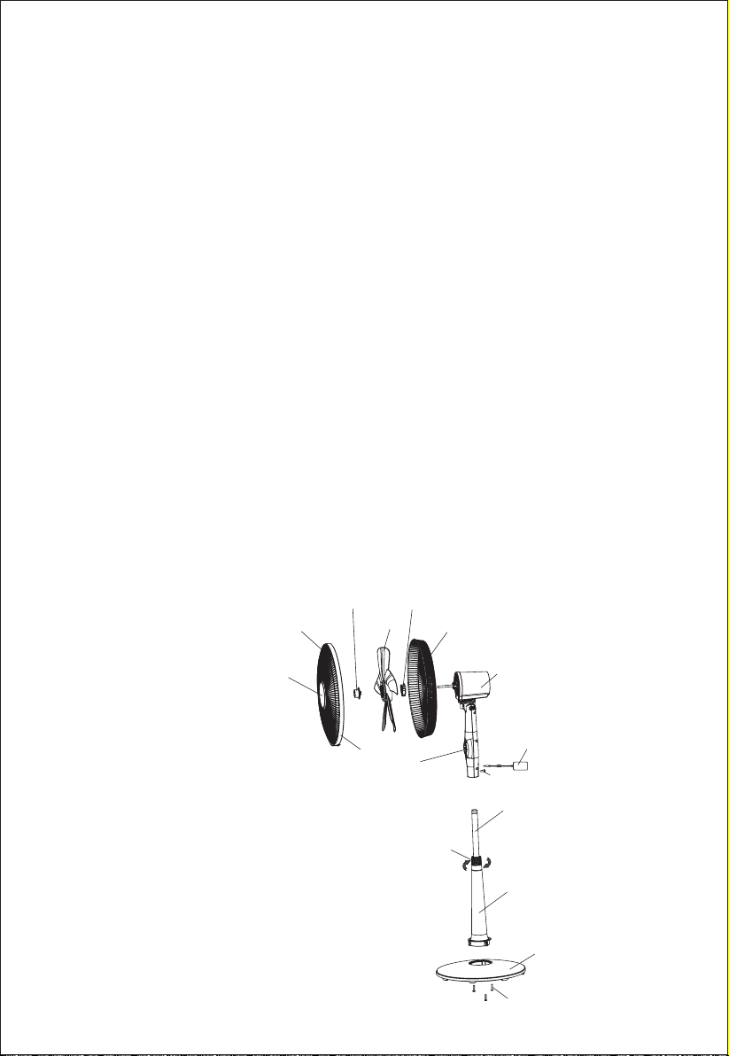
PARTS
Spinner
Front guard
Decorative Cover
Blade set
Plastic nut
Rear guard
Motor
Ring
Control Panel
Height Adjustment Ring
1
AC Adapter
Screw
Inner Pole
Extension Pole Stand
Base
Screw
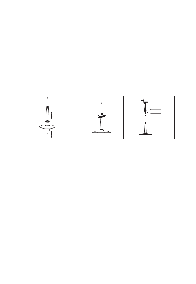
BASE, POLES & HEAD UNIT ASSEMBLY
1. Uncrew and remove the three screws from the underside of the Extension Pole
Stand. Insert the bottom of the Extension Pole Stand into the Base as shown in
Fig.1. Carrfully turn the Base and Stand upside down and use the three screws
to attach the Base and Stand together.
2. Loosen the height adjustment ring and pull the Inner Pole up to the desired height
(Fig. 2). Tighten the ring. Note: The Inner Pole may slide all the way down inside
the stand when loosening the adjustment ring. Invert the stand so that the Inner
Pole slides out for adjustment.
3. Loosen the attachment screw at the bottom of the Head Unit back side (Fig. 3).
Slide the Head Unit down onto the top of the Inner Pole as far as it will go.
Tighten the attachment screw.
Fig.1
F
ig.2 Fig.3
Loosen
Head unit
Attachment screw
GUARD & FAN BLADE ASSEMBLY
1. Unscrew and remove the spinner clockwise (or obtain from parts bag), and the
plastic nut counterclockwise. You may have to hold the shaft in place with one
hand to unscrew the spinner with the other. Position the rear guard against the
motor face so that the two pins on the motor face fit through the matching holes
in the rear guard. Tighten the rear guard into place with the plastic nut. (Fig.4)
2. Remove and discard the PVC sleeve from the motor shaft. Mount the blade set
onto the motor shaft through the center hole in the blade set. Insert the pin on
the motor shaft into the notches on the back of the blade set. Turn the spinner
counterclockwise onto the shaft to tighten the blade set into place. (Fig.5)
3. Remove the small screw from the clear plastic clasp on the bottom of the front
guard and set aside. Place the front guard over the rear guard so that the tab
at the top of the front guard fits over the rear guard rim (Fig. 6). Push the two
guards together. Close the clasp at the front guard bottom over the rear guard
rim, and re-insert and tighten the small screw removed earlier.
4. Insert the jack end of the AC adapter cord into the port for it just above the Head
Unit attachment screw. Insert the adapter plug end into an electrical outlet. The
fan is now ready to use.
2
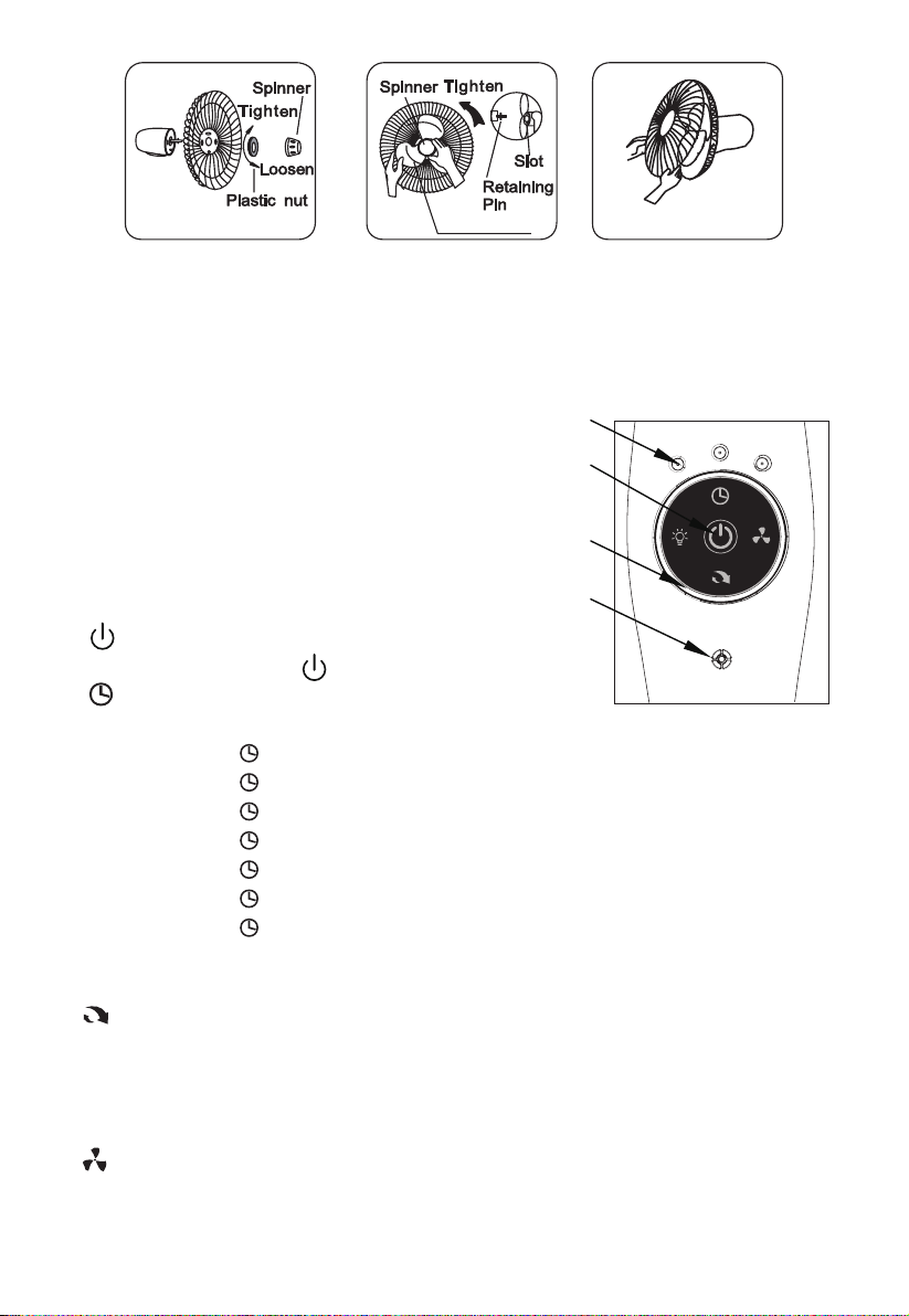
Fig.4 Fig.5
Blade Set
Fig.6
Note: The AC adapter is supplied with the product together. Don't use other AC
adapter. If your AC adapter is damaged, call customer assistance number:
1-855-438-7899 to purchase one new AC adaper.
OPERATING INSTRUCTIONS
I. CONTROLS (Figure 7)
1. Control Panel Keys
2. Speed Indicator Lights
3. Timer Set Indicator Lights
4. Receiver
II. CONTROLS PANEL
1. “ ” ON/OFF KEY
To turn fan on, press the “ ” key.
2. “ ” TIMER KEY
Choose from 1 to 7 hour setting as follows:
• 1 hour: Press the “ ” Timer key once. The indicator “1H” will be lit.
• 1 hour: Press the “ ” Timer key twice. The indicator “2H” will be lit.
• 1 hour: Press the “ ” Timer key three times. The indicators “1H” & “2H” will be lit.
• 1 hour: Press the “ ” Timer key four times. The indicator “4H” will be lit.
• 1 hour: Press the “ ” Timer key five times. The indicators “1H” & “ 4H” will be lit.
• 1 hour: Press the “ ” Timer key six times. The indicators “2H” & “4H” will be lit.
• 1 hour: Press the “ ” Timer key seven times. The indicators “1H”,”2H” & “4H”
will be lit.
Press the Timer key an eighth time to turn the Timer feature off.
3.“ ” OSC KEY
To activate the Oscillation feature, press the Oscillation key once. Press the
Oscillation key again to turn the Oscillation feature off. In Oscillation mode, the fan
will rotate slowly back and forth from right to left to direct the air flow over a
broader area.
4.“ ” SPEED KEY
When the fan turned on, repeatedly press the Speed key to change the fan speed
in a sequence from LOW to MEDIUM to HIGH.
3
1
2
4
Fig.7
3
 Loading...