

Page 1
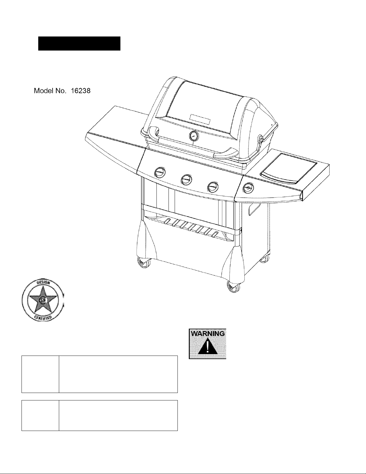
Assembly and Operation
Ken more
Liquid Propane Gas Gril
THIS GRILL IS FOR OUTDOOR
USE ONLY
CAUTION
A
CAUTION
A
Sears, Roebuck and Co., Hoffman Estates, IL 60179, U.S.A www.sears.com
Read and follow all Safety Statements,
Assembly instructions, and Use
and Care Manual Directions before
attempting to assemble and cook.
Some parts may contain sharp edges,
wear protective gloves if necessary.
Customer Service
Toll Free 1-800-396-3838
To Installer/Assembler: Leave these
instructions with consumer.
To Consumer: Keep this manual for future
reference.
Failure to follow all manufacturer’s
instructions could result
in serious personal injury and/or
property damage.
SP5327A-37
Page 2
Table of Contents
Limited Warranty
Warranty,,...
Safety................................................................2
Caring for your equipment................................3
Hardware..........................................................6
Assembly.....................................................7-24
Operation...................................................25-26
Cleaning and Maintenance
Parts................................................................29
Exploded view.................................................30
Troubleshooting
Product Record
IMPORTANT: Fill out the product record
information below.
................................................. 2
.......................
..............................................
27-28
31
One Year Full Warranty on Kenmore Grill
For one year from the date of purchase Sears will repair or
replace, at our option, any grill part (except for paint finish) that is
defective in materia! or workmanship. If this grill is defective in
material or workmanship within one year from the date of
purchase, contact Sears at 1-800-4-IVIY-HOME®.
Additional Warranty on Specific Grill Parts
For the time periods listed below, Sears will replace the following
specific grill parts free of charge if they are defective in material
of workmanship (Part replacement only, labor not included) :
Lifetime on Cast Aluminum Lids and Bottoms
Five years from purchase date on Stainless Burners
All warranty coverage excludes ignitor batteries and any paint
loss or rusting which are either expendable parts that can wear
out from normal use in less than a year, or are conditions that
can be the result of abnormal use, accident or improper mainte
nance.
All warranty coverage is void if this grill is used for commercial or
rental purposes.
Model Number
UPC (on carton) Label Lot # GG.
Serial Number
Date Purchased
Combustion byproducts produced when
using this product contain chemicals
known to the State of California to cause
cancer, birth defects, or other reproductive
harm.
WARNING
IF YOU SMELL GAS:
1. Shut off gas supply to the
appliance.
2. Extinguish any open flame.
A
Am.
3. Open lid.
4. If odor continues, immediately
call your gas supplier or your fire
department.
This warranty gives you specific legal rights, and you may also
have other rights which vary from state to state.
Sears, Roebuck and Co., Dept. 817WA, Hoffman Estates, !L 60179
SAFETY INSTRUCTIONS
WARNING
A
Am.
• Do not store or use gasoline or
other flammable vapors and liquids
in the vicinity of this or any other
appliance.
•An LP cylinder not connected
for use shall not be stored in
the vicinity of this or any other
appliance.
© Sears, Roebuck and Co.
Page 3
CAUTION
For residential use only. Do not use for
commercial cooking.
A
WARNING
A
Call Grill Service Center For Help And Parts
If you have questions or need assistance during
assembly, please call 1-800-396-3838. You will be
speaking to a representative of the grill manufacturer
and not a Sears employee. To order new parts call
Sears at 1-800-4-MY-HOiVIE®.
CARBON MONOXIDE HAZARD
Combustion byproducts include carbon
monoxide which has no odor and can
cause serious injury or death. Never use
inside homes, vehicles or tents.
Failure to ensure correct venturi tube assembly
may result in a hazardous fire or explosion
causing serious bodily injury and/or property
damage.
CARING FOR YOUR EQUIPMENT
INSTALLATION
THE INSTALLATION OF THIS APPLIANCE MUST
CONFORM WITH LOCAL CODES OR, IN THE
ABSENCE OF LOCAL CODES;
• In Canada: must conform to CAN/CGA- B149.2 Propane
Installation Code or CAN/CGA B149.1 Natural Gas
Installation.
• In the U.S.A.: must conform to National Fuel Gas Code
ANSI Z223.1.
WARNING
When deciding where to place your appliance,
follow these minimum clearance distances to
adjacent combustible materials:
A
GETTING FAMILIAR WITH YOUR GRILL
WARNING
A
Your grill is properly assembled.
There are no leaks in the gas supply system
(see ‘Leak Testing’ section).
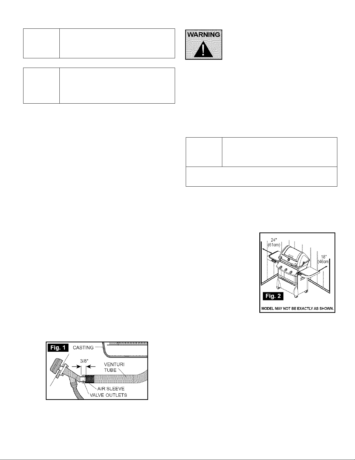
The burner is properly assembled with the venturi tubes
seated over the valve outlets (Figure 1 below) and there
are no blockages present in the venturi tubes
(see ‘Cleaning 'Venturi Tubes’ section).
Electrical supply cords and/or gas supply hoses are kept
away from any heated surfaces.
Your grill is positioned in a safe location
(see ‘Installation’ section).
Figure 1.
• Ensure valve outlets (orifices) are assembled 3/8” (1 cm)
into the venturi tubes.
• Check to see that the valve outlets and venturi tubes are
parallel to the bottom of the base casting of your appliance.
Do not use your grill until you have read and
understood all of the information in this manual. It
is extremely important to be sure that:
• 24 inches (61 cm) from side of unit (See Figure 2)
• 18 inches (46 cm) from back of unit (See Figure 2)
FOR YOUR OWN SAFETY:
• Only use your grill OUTDOORS in a well ventilated area
- preferably 10 feet (3m) from your residence or any
outbuildings.
• Always keep the area around your grill clear of any
combustible materials, gasoline, or other flammable liquids.
• DO NOT operate this grill under overhead or unprotected
construction.
• DO NOT obstruct the
flow of combustion and
ventilation air to the grill.
• DO NOT use in garages,
sheds, tareezeways, or
other enclosed areas.
• DO NOT store a spare L.P.
(propane) cylinder under or
near your grill.
• DO NOT leave your
grill unattended while in
operation.
• DO NOT allow children to
operate or play near your
grill.
• DO NOT use while under the influence of alcohol or drugs.
• DO NOT install/use in or on recreational vehicles and/or
boats
ELECTRICAL CAUTION
• If any accessory installed on this grill requires an external
electrical power source, it must be electrically grounded in
accordance with local laws or in the absence of local laws,
with the Canadian Electrical Code CSA C22.1 or in the U.S.,
with the National Electrical Code ANSI-NFPA70.
• The three-prong plug provides protection against shock
hazard and should be plugged directly into a properly
grounded three-prong receptacle. Do not cut or remove the
grounding prong from this plug.
• Ensure all electrical supply cords and fuel supply hoses are
kept well away from any heated surfaces.
Page 4
L.P. GAS CYLINDER
Gas cylinders manufactured today have
mechanisms to provide worry free
grilling year round:
Q.C.C.1 or Type 1-Quick Connect
Coupling Valve, ensure fast tank
hook-ups requiring only hand
tightening. The redundant
valve system inhibits the flow
of gas to the burner If the
connection is not correct.
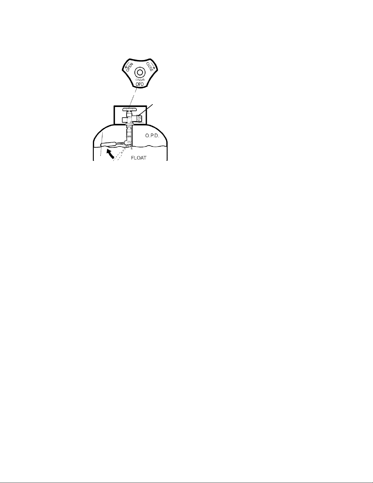
O.P.D, or Overfill Protection
Device prevents accidental
gas leaks caused by cylinder
'over-pressurization', the
leading cause of cylinder gas
leaks. The float in the tank
will automatically stop filling at
80% capacity, leaving a
20% area for the expansion
of liquid. Without this safety
feature, the relief valve may
open and discharge propane,
creating a potential safety hazard. An O.P.D. cylinder is easily
distinguished by its triangular hand wheel valve. (Figure 3)
FILLING STOPS AT 80%
NEW OPD
HANDWHEEL
'External threads
on Coupling Valve.
Fig. 3
1 SPECIFICATIONS
Self-contained propane gas grill systems are designed to be
used only with a 20 lb (9.1 kg) propane cylinder, equipped with
a Type 1 cylinder valve and incorporating an overfill protection
device
(0,P,D).THE CYLINDER SHOULD NOT EXCEED 18
1/2" (472 MM) !N HEIGHT AND 12 1/2" (317 MM) IN DIAMETER.
This grill cannot be connected to a #510 P.O.L type valve
(ones with left-hand threads).
The cylinder for your gas grill must be constructed and marked
in accordance with the specifications of L.P. gas cylinders:
In Canada: The National Standards of Canada CAN/CSA-B339,
Cylinders, Spheres and Tubes for Transportation of
Dangerous Goods; and Commission.
In the U.S.: U.S. Department of Transportation (D.O.T.)
THE CYLINDER MUST ALSO BE EQUIPPED WITH:
a. A shut-off valve terminating in a proper cylinder valve outlet
specified in current standards:
• Canada: CAN/CGA - 1,6a - M98 - Outdoor Gas Grills Amend. 1.
• U.S.: ANSI Z 21.58a-1998 OUTDOOR COOKING
APPLIANCES.
b. A listed overfilling protection device (O.P.D.).
c. A safety relief valve having direct communication with the
vapor space of the cylinder.
d. A collar to protect the tank shut off valve.
e. An arrangement for vapor withdrawal.
f. A bottom ring for mounting.
SAFETY:
• Always turn off the cylinder valve tightly when your grill is
not in use.
• Handle tank valves with care.
• Never connect an unregulated L.P. gas cylinder to your grill.
• Never store a spare cylinder under or near your grill when in
use.
• Never subject any cylinder to excessive heat or direct
sunlight.
• Always keep your in-use cylinder securely fastened in an
upright position.
• Do not insert any foreign objects into the valve outlet. You
may damage the back-check. A damaged back-check can
be the source of a leak. Leaking propane may result in
explosion, fire, severe personal injury or death.
• DO NOT fill the cylinder beyond 80% full.
WARNING
A
If the above instructions are not followed
exactly, a fire causing death or serious injury
may occur.
DO NOT CONNECT TO A PROPANE GAS CYLINDER
EXCEEDING THIS CAPACITY, OR USE A CYLINDER WITH
ANY OTHER TYPE OF VALVE CONNECTION DEVICE.
The Type 1 valve is recognizable by the large externa! thread on
the outlet part of the valve. Non Type 1 valves do not have
these exterior threads. Any attempt to connect a regulator, with
other than the:
i) Mating Type 1 connector (recognized by the large black
coupling nut)
or
ii) Standard #510 P.O.L. fitting, by use of adapters or any other
means.
Could result in damage, fire or injury and may negate
the important safety features designed into the Type 1 system.
The connection of a #510 P.O.L. fitting will not provide the flow
control or temperature shut-off features built into the complete
Type 1 System.
Page 5
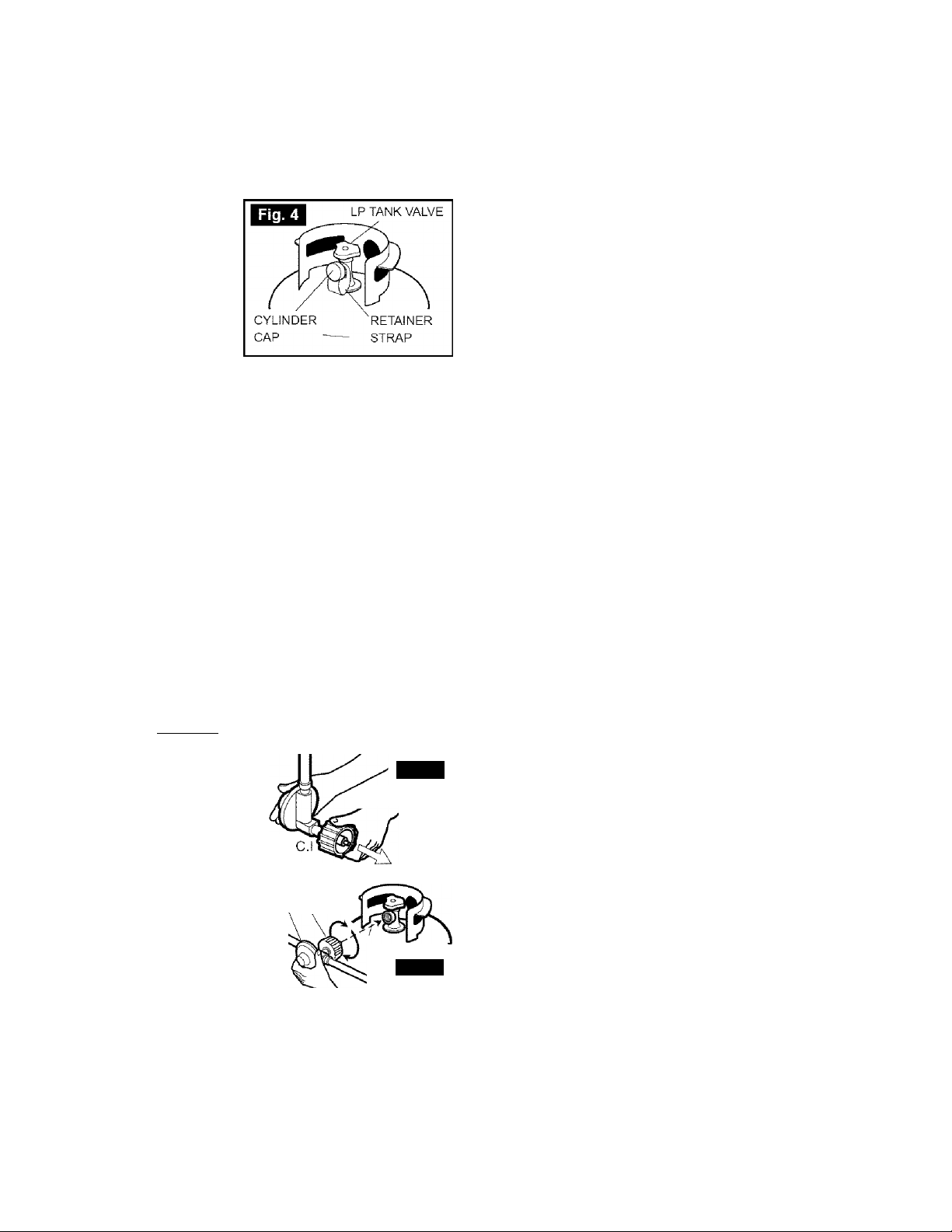
2. TRANSPORTATION AND STORAGE:
WARNING: Although it is safe when used properly, careless
handling of the propane gas cylinder could result in fire,
explosion, and/or serious injury.
PROPANE GAS IS HEAVIER THAN AIR, AND WILL COLLECT IN
LOW AREAS, INCREASING THE ABOVE RISKS THEREFORE:
• ALWAYS use the cylinder
cap provided with your
cylinder whenever the
cylinder is not connected
to your grill. (Figure 4)
• DO NOT store in a
building, garage or any
other enclosed area.
Store in a well-ventilated
area.
• DO NOT store near any
gas burning apparatus or in any
high-heat areas such as a closed car or trunk.
• Transport and store the cylinder in an upright position — do
not tip on its side.
• Store out of reach of children.
• DO NOT smoke while transporting a cylinder in your vehicle.
FILLING:
FOR SAFETY REASONS, IF AN OPTIONAL L.P. GAS
CYLINDER WAS SUPPLIED WITH YOUR GRILL, IT HAS
BEEN SHIPPED EMPTY. THE CYLINDER MUST BE PURGED
OF AIR AND FILLED PRIOR TO USING ON YOUR GRILL.
WHEN GETTING YOUR CYLINDER FILLED:
• Allow only a qualified L.P. gas dealer to fill or repair your
cylinder.
• DO NOT allow the cylinder to be filled beyond 80% full.
• Make sure the L.P. gas dealer checks the cylinder for leaks
after filling.
VVAKNINO : If the above instructions are not followed
exactly, a fire causing death or serious injury
may occur.__________________________________
HOSE & REGULATOR
PROPANE GAS MODELS:
Your grill is designed to operate
on L.P. (propane) gas at a
pressure regulated at 11" water
column(2.74 kPa). A regulator
preset to this pressure is supplied
with the grill and MUST be used. REGULATOR
This regulator is equipped with \Q.C.C.I
the Q.C.C. Type 1, quick connect
coupling system, which
incorporates the following safety
features: (Figure 5)
• It will not allow gas to flow until a
positive seal has been made. (Figure 6)
• It has a thermal element that will shut off the flow of gas
between 240 and 300°F (115 and150°C).
• It also has a flow-limiting device which,when activated, will
restrict the flow of gas to 10 cubic feet per hour (0.28 cubic
meters per hour).
Q.C
Fig. 5
REGULATOR
STRAIGHT
Fig. 6
Prior to attaching the propane cylinder to the hose and regulator,
be sure the cylinder valve and the appliance valves are OFF. The
cylinder valve is turned off by rotating the handwheel (see Figure 3)
clockwise (left to right) until it stops and all appliance valves should
be in the off position. When attaching the regulator to the cylinder,
make sure that the small probe in the nipple is centered in the
mating Q.C.C. 1 cylinder valve (see Figure 6). Turn the right hand
threaded Q.C.C. 1 black nut onto the valve in a clockwise motion
until there is a positive stop. DO NOT USE A WRENCH, HAND
TIGHTEN ONLY.
Should the large black thermally sensitive coupling nut be
exposed to temperatures above 240 and 300°F, it will soften
and allow the regulator probe to disengage from the cylinder
valve — thereby shutting off the flow of gas. Should this
occur, do not attempt to reconnect the nut. Remove the entire
regulator assembly, and replace it with a new one. (See
‘REPLACEMENT PARTS' section in assembly instructions or
contact us at 1 -800-396-3838)
The cause of the excessive heat should be determined and
corrected before operating your grill again. The regulator probe
also contains a flow-sensing element, which will limit the flow of
gas to the regulator to a manageable amount (10 cubic feet per
hour) in the event of a hose or regulator rupture. If it is evident
that the flow control device has been activated, the cause of the
excessive flow should be determined and corrected before using
your grill again.
Please refer to the troubleshooting guide on page 34 or
contact us 1-800-396-3838.
NOTE; IMPROPER LIGHTING PROCEDURES CAN
CAUSE THE FLOW CONTROL TO ACTIVATE, RESULTING
IN REDUCED HEAT OUTPUT. IF THIS IS SUSPECTED,
RESET THE FLOW CONTROL BY SHUTTING OFF ALL
BURNER CONTROLS AND THE CYLINDER VALVE. WAIT
30 SECONDS, THEN TURN THE CYLINDER VALVE ON
EXTREMELY SLOWLY - WAIT 5 SECONDS AND TURN THE
BURNER VALVE ON AND LIGHT AS NORMAL.
• Never connect a propane gas grill to an unregulated
propane gas supply or any other gas. Do not attempt to
alter the hose or regulator in any way.
• The connection fitting must be protected when disconnected
from the propane tank. If the fitting is allowed to drag on
the ground, nicks and scratches could occur resulting in a
leak when connected to the propane tank,
PROPANE AND NATURAL GAS MODELS:
' Do not allow any grease (or other hot material) to fail onto
the hose, or allow the hose to come in contact with any hot
surfaces of the grill.
• Visually inspect the entire length of the hose assembly
before each use of the grill. If it is evident there is
excessive abrasion/wear, or the hose is cut, it must be
replaced prior to using your grill. Only the hose assembly
as specified in the Parts List should be used.
' Follow the ‘LEAK TEST’ instructions before lighting your
grill for the first time, every time a propane cylinder is
refilled, if any gas component is changed, if the regulator
flow-limiting device has been activated, after prolonged
periods of storage or non-use or at least once per season.
Page 6
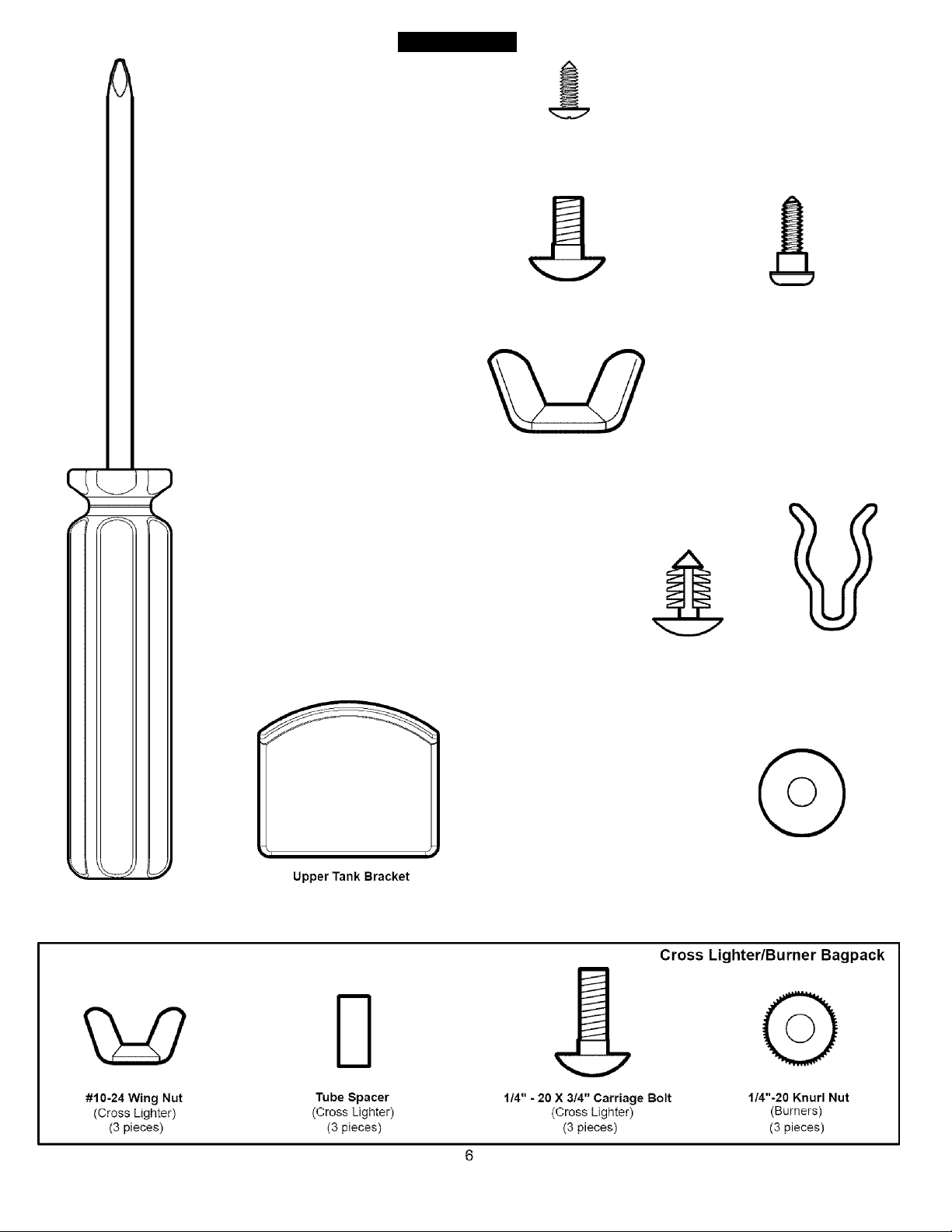
HARDWARE
Master Bagpack
#8-32 X 3/8 Tapping Screw
(2 pieces)
1/4"-20X2" Carriage Bolt
(8 pieces)
#10x1/2 Phillips Screw
(24 pieces)
1/4" - 20 X 1/2" Carriage Bolt
(2 pieces )(Blaok)
1/4"-20 Large Body Tapered Wing Nut
(2 pieces)
Shoulder Screw
(2 pieces)
1/4”-20 Wingnut
(10 pieces)
(2 Black)
#2 Phillips Screwdriver
(1 piece)
#6-32 Wing Nut
(Overlay)
(2 pieces)
(Tank)
(1 piece)
#10-24 Wing Nut
(Sideburner)
(1 piece)
MI
#10-24 Wing Nut
(Handle)
(2 pieces)
Push Pin
(Side Panel)
(2 pieces)
Hinge Clip
(Lid)
(1 piece)
Handle
1/4-3/4 Washer
(2 pieces)
Page 7
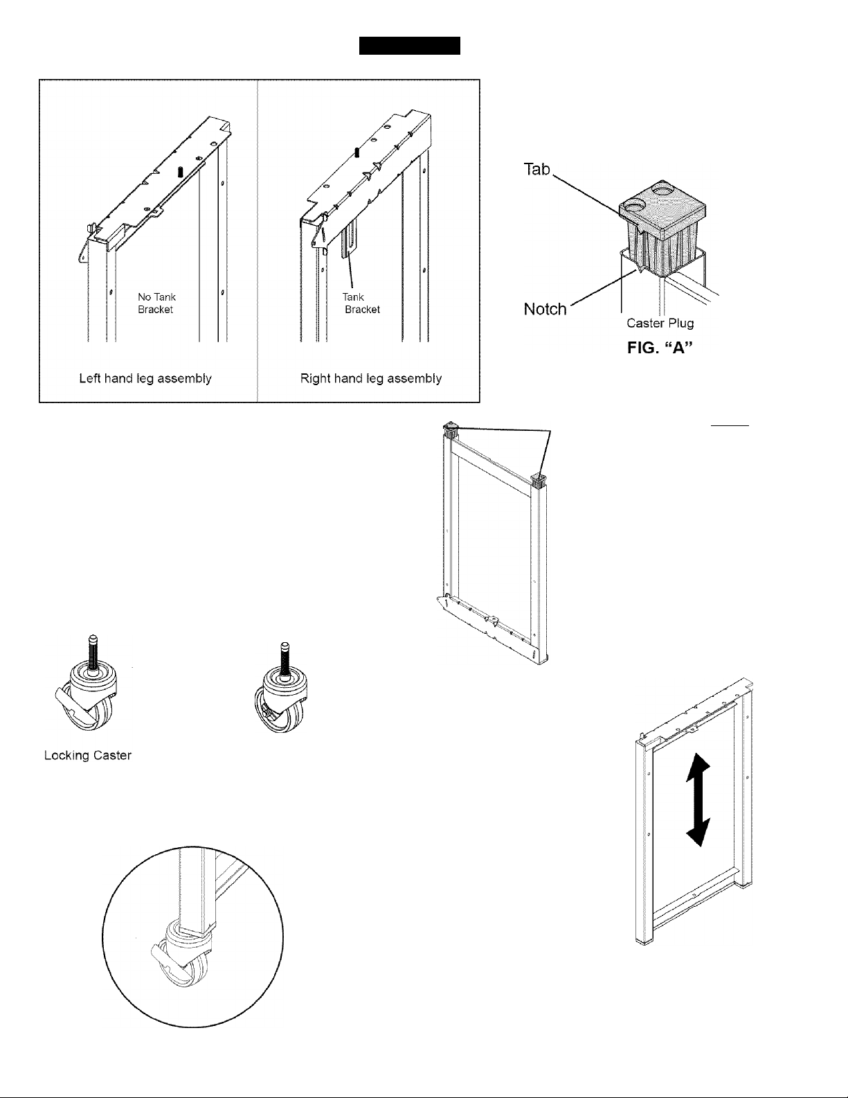
ASSEMBLY
1. Turn leg assembly upside down as
shown and insert caster plug.
Make sure caster plug tab is in line with
notch in leg. {SEE FIG “A”)
2. Turn leg assembly over and tap on a hard surface
until the caster plugs are fully seated.
Non-Locking Caster
3. Insert locking casters into the caster plugs on front of leg
assemblies and press in until caster is fully seated as shown.
Insert caster into holes on outside
corner of caster plug as shown.
Leg Assembly
(Left Hand shown)
Console mounting
tabs are on front
side of leg
assemblies.
4. Insert non-locking casters into the caster plugs
on rear of leg assemblies.
Page 8
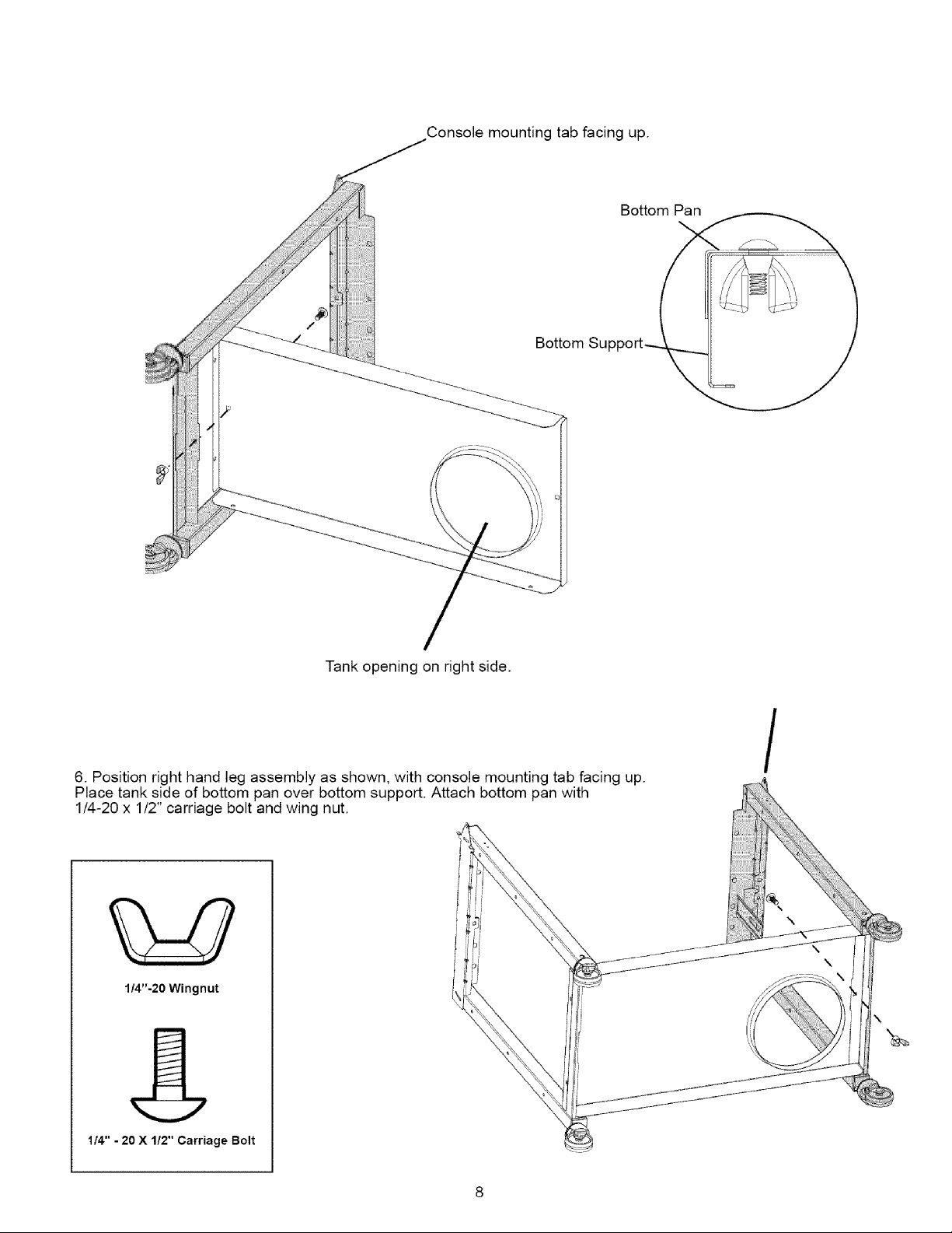
5. Position left hand leg assembly as shown with console mounting tab facing up.
Place non-tank side of bottom pan over bottom support. Attach bottom pan with
1/4”-20 X 1/2” carriage bolt (Black) and wing nut (Black).
Console mounting tab facing up.
Page 9
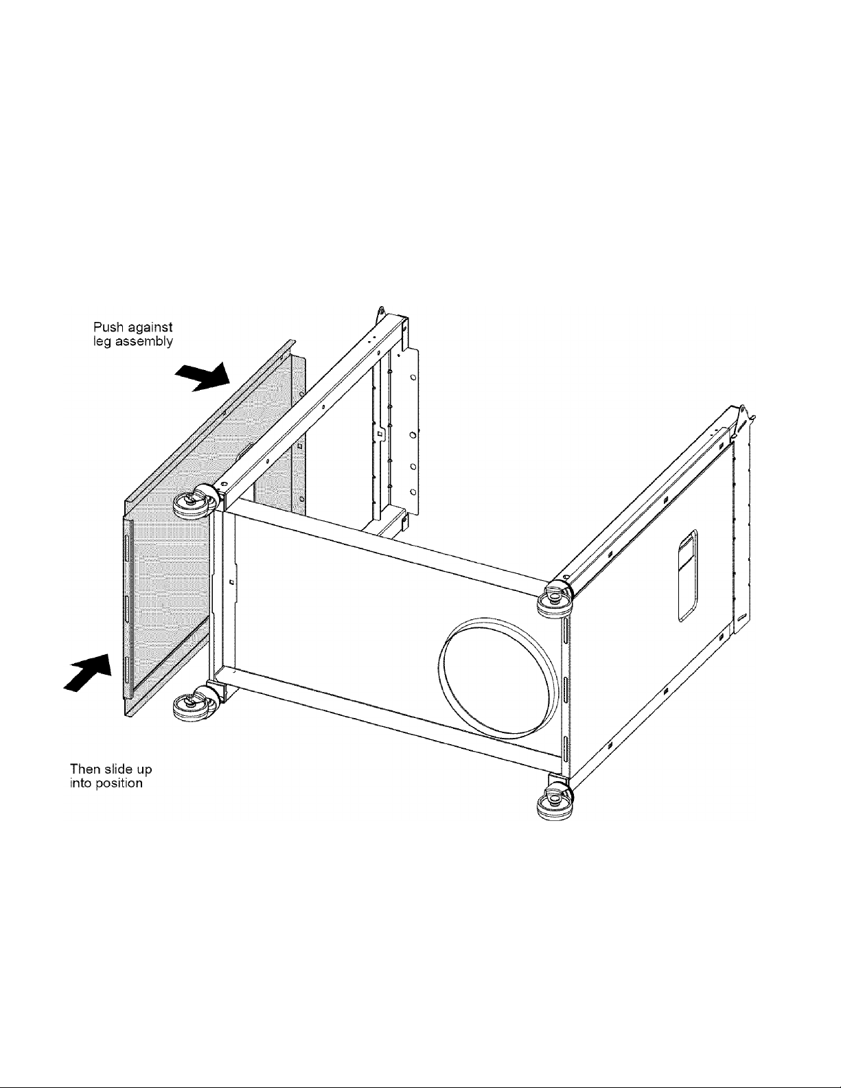
7. Position side panels over legs and slide up into position.
Bottom flange of side panel hooks over bottom support.
Page 10

Get it fixed, at your home or ours!
Your Home
For repair-in your home -of all major brand appliances,
lawn and garden equipment, or heating and cooling systems,
no matter who made it, no matter who sold it!
For the replacement parts, accessories and
owner’s manuals that you need to do-it-yourself.
For Sears professional installation of home appliances
and items like garage door openers and water heaters.
1-800-4-IV1Y-HOIV1E ® (1-800-469-4663)
Call anytime, day or night (U.S.A. and Canada)
www.sears.com www.sears.ca
Our Home
For repair of carry-in items like vacuums, lawn equipment,
and electronics, call or go on-line for the location of your nearest
Sears Parts & Repair Center.
1-800-488-1222
Call anytime, day or night (U.S.A. only)
www.sears.com
To purchase a protection agreement (U.S.A.)
or maintenance agreement (Canada) on a product serviced by Sears:
1-800-827-6655 (U.S.A.) 1-800-361-6665 (Canada)
Para pedir servicio de reparación
a domicilio, y para ordenar piezas:
1-888-SU-HOGAR
(1-888-784-6427)
Au Canada pour service en français:
1-800-LE-FOYER
(1-800-533-6937)
www.sears.ca
® Registered Trademark / ™ Trademark / Service Mark of Sears, Roebuck and Co.
® Marca Registrada / ™ Marca de Fábrica / Marca de Servicio de Sears, Roebuck and Co.
Marque de commerce / “ Marque déposée de Sears, Roebuck and Co. ) Sears, Roebuck and Co.
Page 11
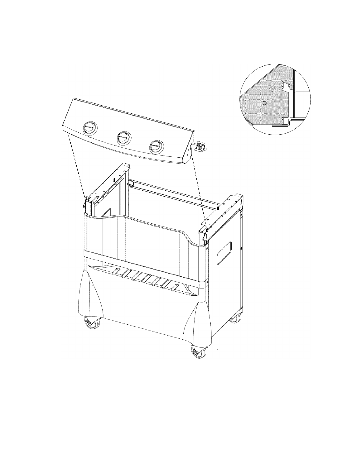
10. Position console/valve assembly over tabs as shown.
Locate Console on tabs as shown.
(Right side shown)
11
Note: Check wires from switch harness to ensure
that they are not against any sharp surfaces.
Page 12
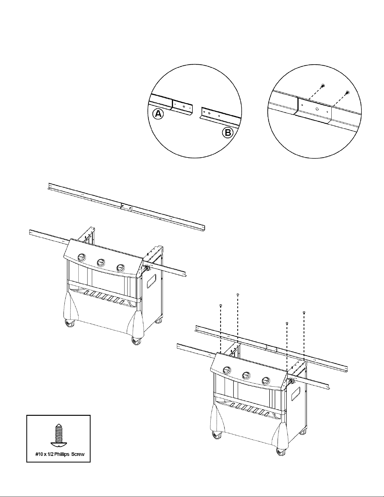
11. Assemble shelf support brackets by sliding shelf bracket (A) and Shelf bracket (B) together while paying
close attention to hole alignment, and attach the two with (2) #10 x 1/2” screws. Repeat for second set.
13. Attach second shelf support bracet using (2) #10 x 1/2”
screws.
12. After joining shelf bracket (A) and (B), align holes
along bottom flange of brackets with corresponding holes
along top edge of casting support. Fasten with (2) #10 x
1/2” screws.
(Note: Bottom flanges on shelf support brackets should
point toward interior of grill.)
12
Page 13
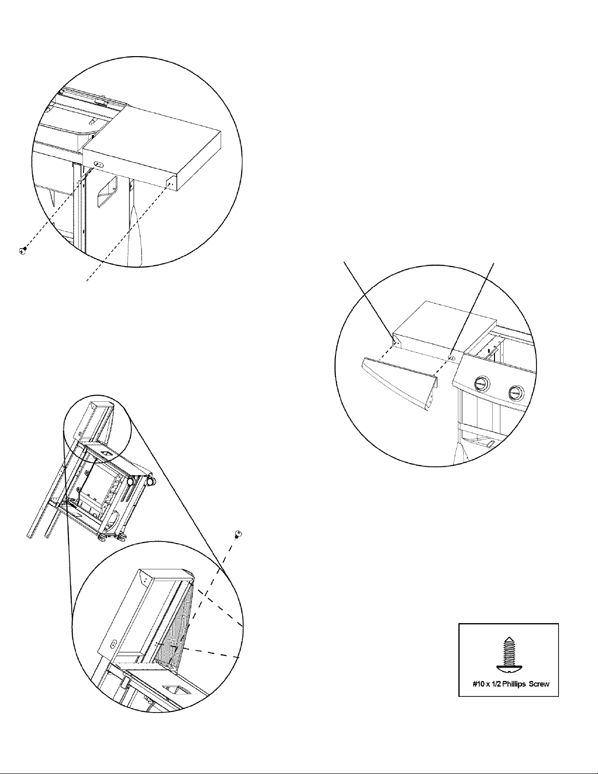
14. Position ieft side shelf over shelf mounting brackets
15. To begin installation be sure to align iarge shelf (holes) with the small holes in
the shelf bracket assembly. Insert (2) #10 x 1/2” Truss head screws (phillips drive)
into largest hole on outside rear corner of shelf carefully aligning with small hole in
shelf mounting bracket. Repeat procedure for inside rear.
^ Rear View
16. To install shelf trim, tilt grill onto opposite shelf supports, align large
holes in shelf bracket and shelf witht the small holes in the shelf trim. Then
place (2) #10 X 1/2” truss head screws into larger holes first (underneath
shelf) and tighten securely.
Outside hole
Inside hole
Front View
17. After securing shelf trim to shelf/shelf bracket, align large hole on inside
flange with large hole in control console and small hole in casting support
bracket and insert (1) #10 x 1/2” truss head screw.
N
S
13
Page 14
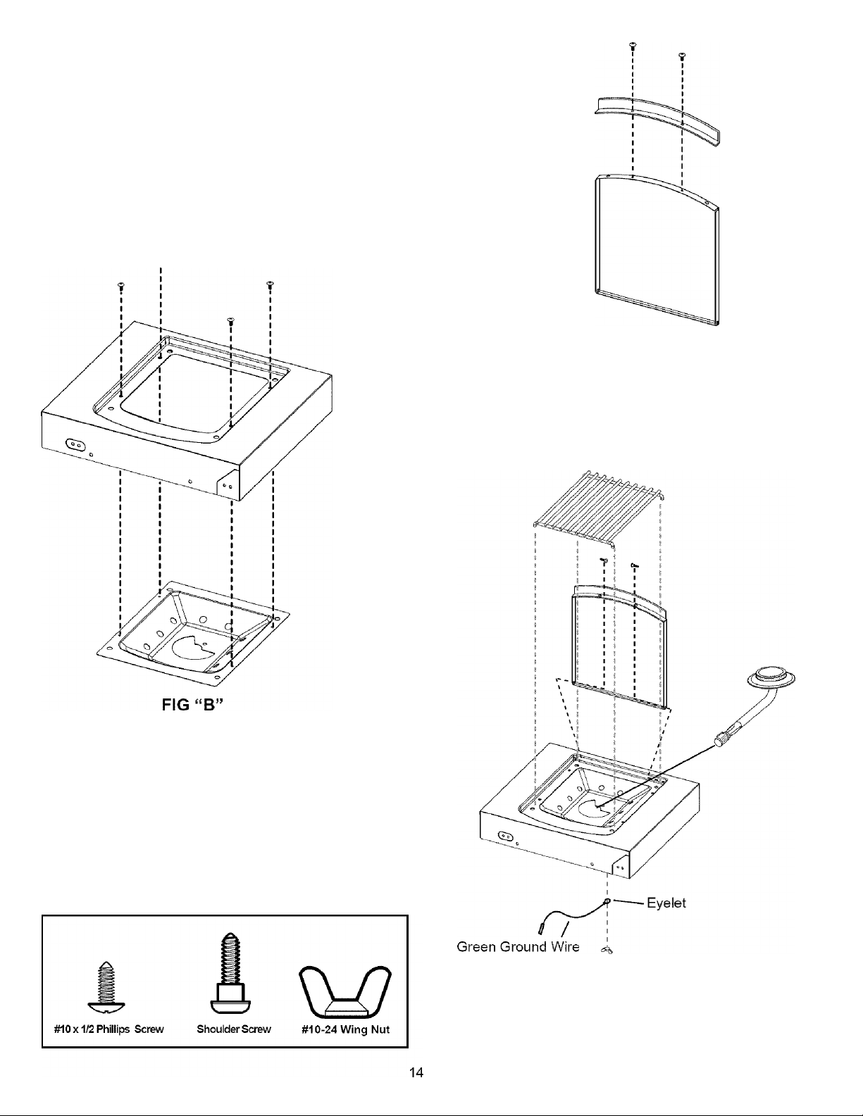
18. Attach side burner lid handle, side burner lid and burner tray.
19. First begin by attaching side burner lid handle to side burner iid using (2) #10 x
1/2” screws.
20. Second, attach side burner tray to side burner base using (4) #10 x
1/2” screws holes as shown. (SEE FIG “B”)
21. Third, attach side burner lid using (2) #10 Shoulder Screws ,
then insert side burner into slot as shown, insert threaded stud on
bottom of side burner into siot provided. After inserting stud into
burner tray attach green ground wire and secure with a #10
wingnut. After inserting side burner into burner base insert cooking
grid by aligning legs of cooking grid with remaining holes in burner
base.
Page 15
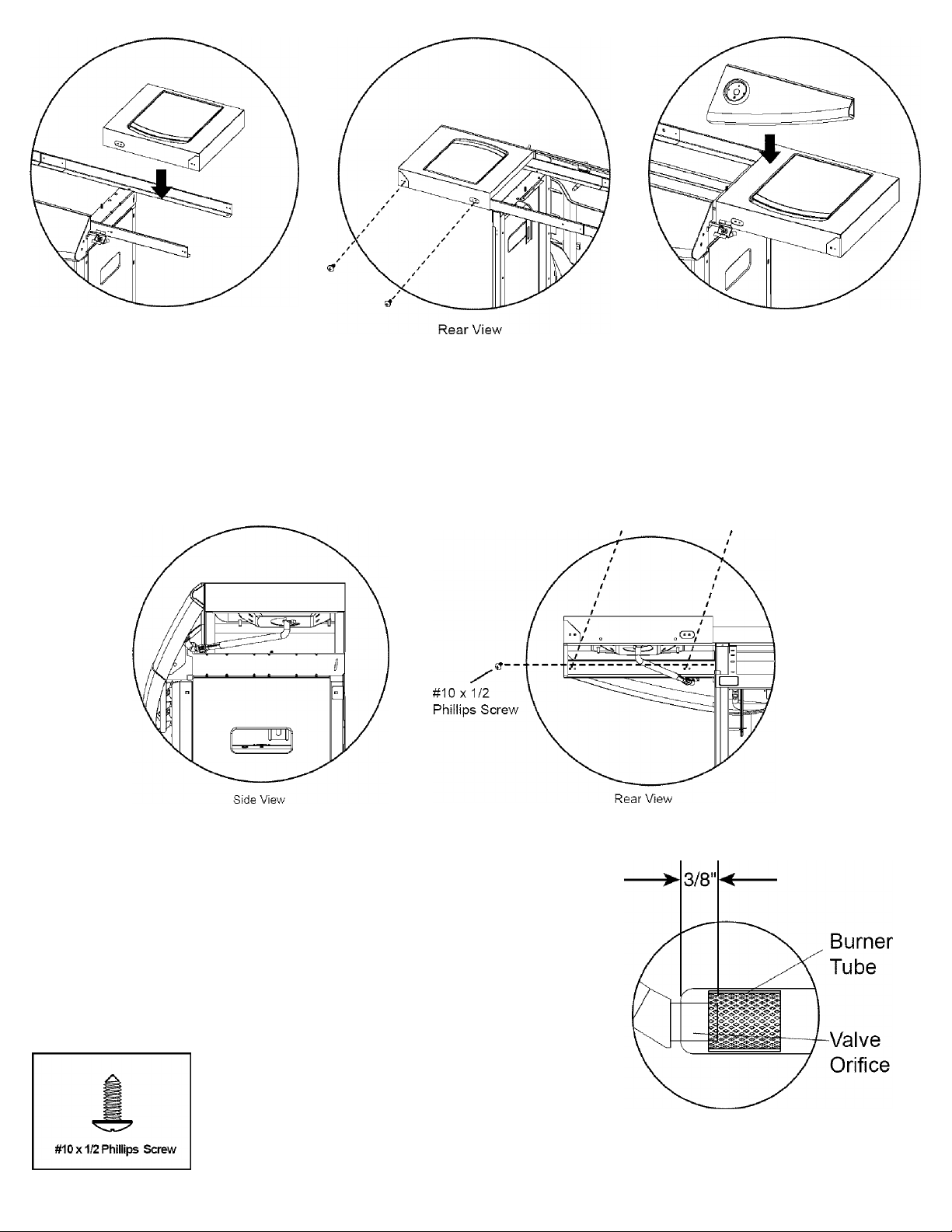
Front View Front View
22. Attach side burner assemblies using shelf mounting procedures
as previously described. (Steps 14 & 15)
23. After attaching side burner base assembly to shelf mounting
brackets insert side burner valve into burner tube of side burner as
shown.
#10 X 1/2
Phillips
Screws
24. After inserting valve orifice into burner tube,
attach shelf trim using (3) #10 x 1/2 phillips screws.
(Steps 16 & 17)
Burner tube must fit over valve orifice as shown.
15
Page 16
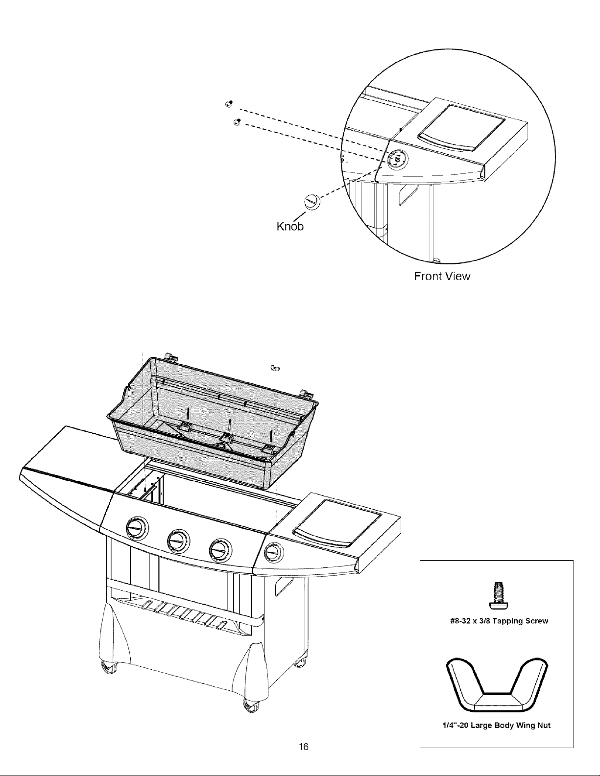
Attach side burner valve and bezel using (2) #8 x 3/8 tapping screws as shown.
Insert side burner knob.
Tapping
Screws
25. Position base casting down over 1/4”-20 studs and secure in place with two 1/4”-20 large
body wing nuts.
Page 17
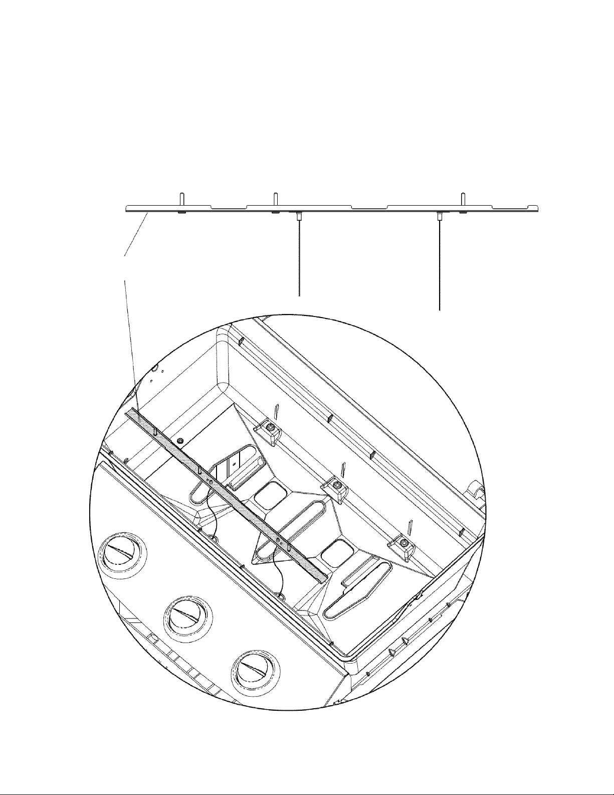
26, Position bottom cross lighter assembly as shown,
being sure to feed ignitor wires through the front holes
in the bottom of the base casting. Bottom cross-lighter just
“lays” loose at this stage of the assembly,
NOTE: Cross lighter top and cross lighter bottom assembly come packaged togetherwth the grill burners. These parts
should be separated prior to this step.
Left side of cross lighter.
17
Page 18
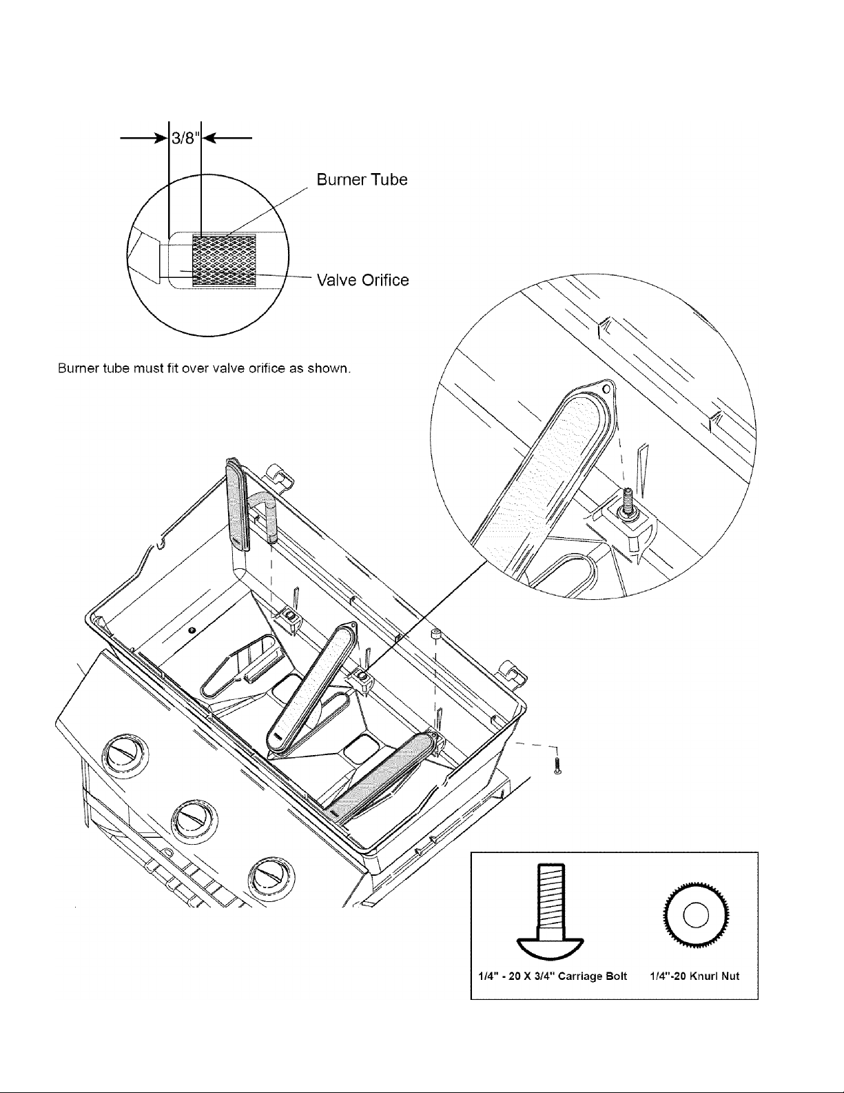
27. Install burners by feeding burner though slot in the base casting and guiding burner tube over orifice
in valve, see illustration below. Secure burners with three 1/4”-20 x 3/4” carriage bolts and 1/4”-20 Knurl nuts.
18
Page 19
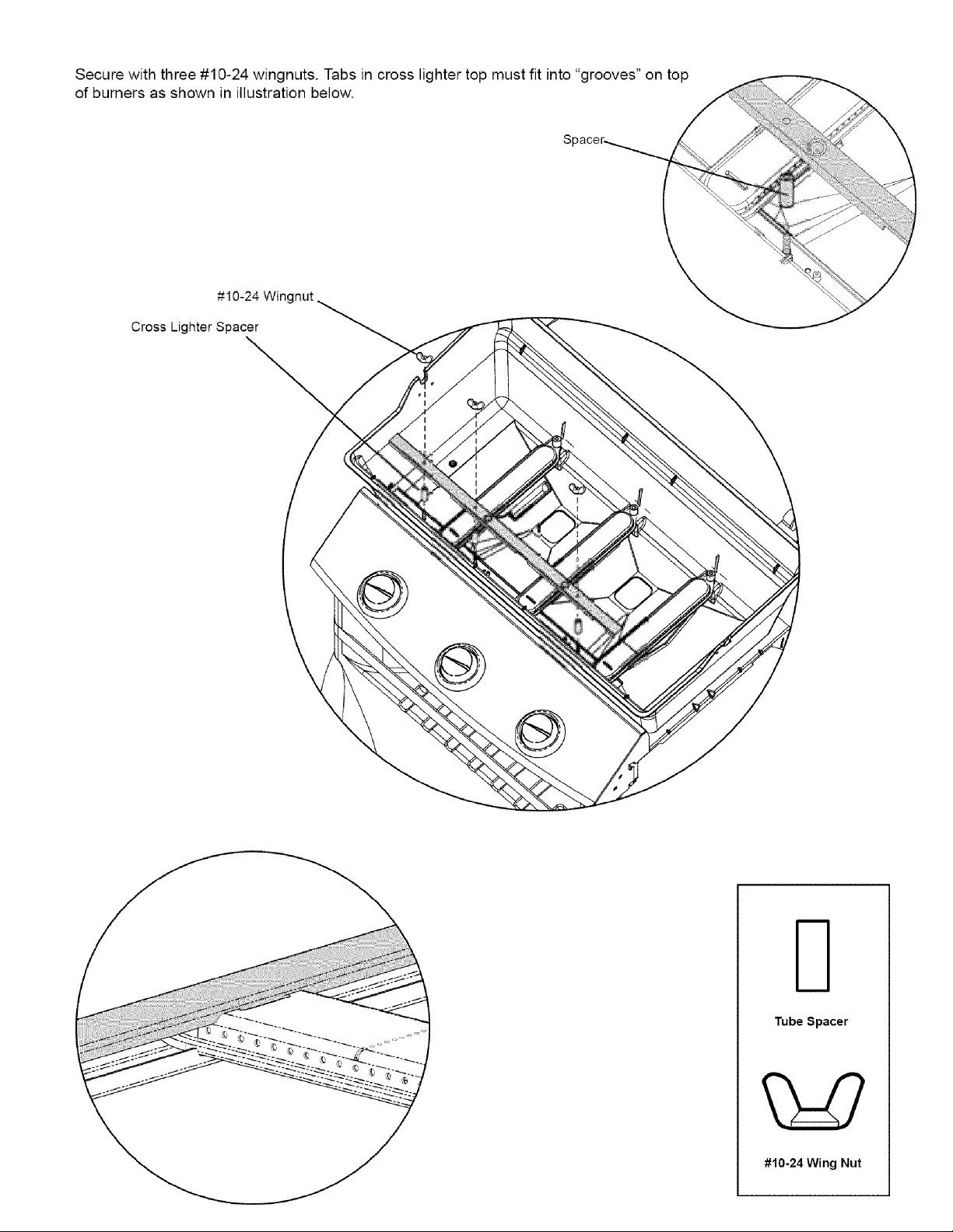
28, Install three cross lighter spacers over threaded studs in bottom cross lighter, then install cross lighter top plate.
IMPORTANT
Tabs in cross lighter top fit
into “grooves” on top of burners.
19
Page 20

29. Install Heat Distribution Plate by placing in position so that the six supports rest on the six ribs in
the base casting.
20
Page 21
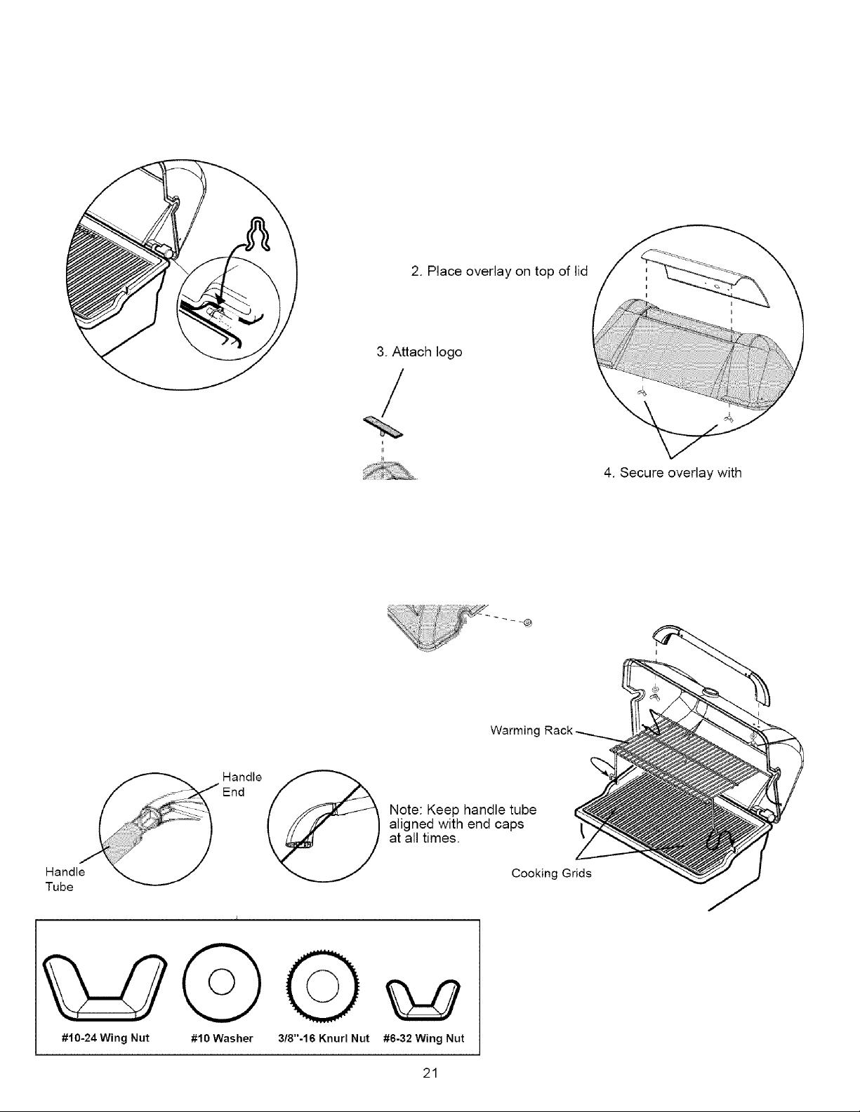
30. Install Lid, Overlay, Handle, Cooking Grid, Warming Rack, Hinge Clip, and Logo.
Install lid before installing overlay, logo, and temperature gauge.
1. Install lid and hinge clip as shown.
NOTE: Tighten wing nuts
secureiy.(Do not overtighten)
5. Install temperature
gauge.
6. Place handle ends into handle tube as shown
Note; Notches in handle tube mate with tab
inside handle cap as shown
- \
(2) # 6 wingnuts.
\
7. Then place handle assembly onto lid and
secure with washers and #10 wingnuts.
8. Install cooking grids and warming rack as
shown.
Page 22
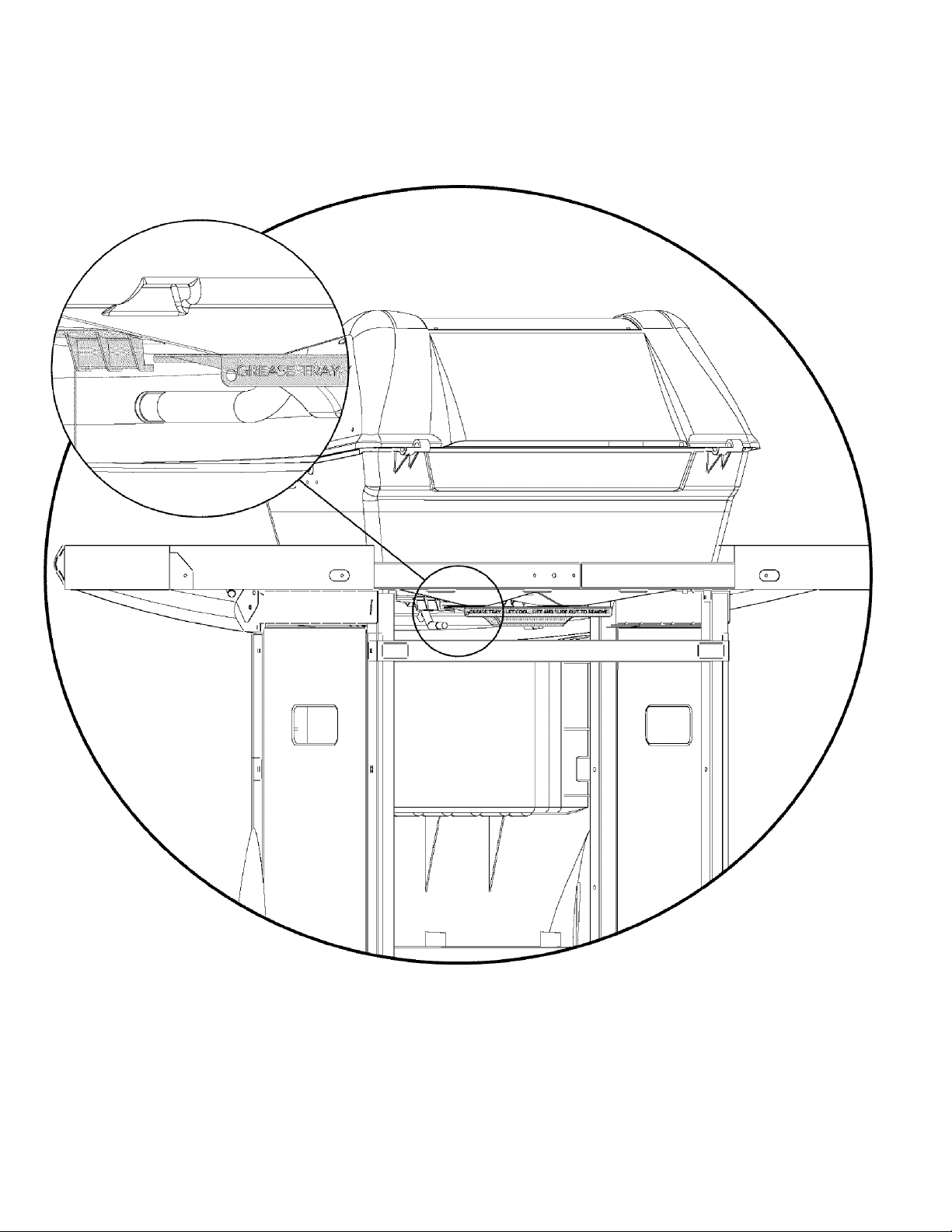
31. Install grease tray from rear of grill by sliding grease tray in on support rails until the
front of the tray drops down over the front of the support rails.
22
Page 23
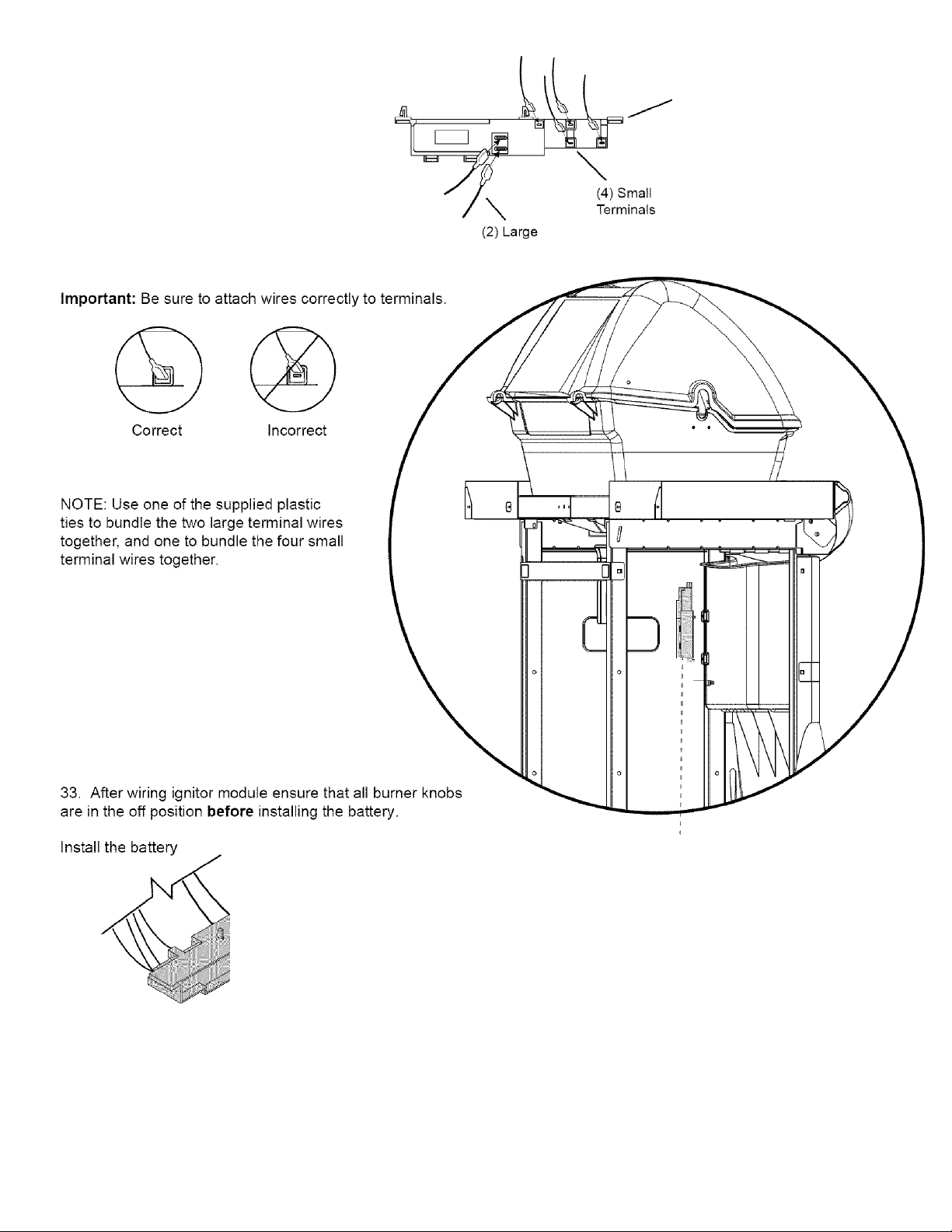
32. Attach the two wires from the cross lighter
and the two wires from the side burner
to any of the four small terminals on
ignitor module as shown.
Next, Attach the two wires from console
assembly to the two large terminals on ignitor
module as shown.
Ignitor Module
Terminals
23
34. Snap ignitor module tabs into
holes on back left side of front
panel as shown.
NOTE: Do not remove ignitor module
once installed. The plastic mounting tabs
on the ignitor “hook” into the mounting
holes and are not designed to be repeatedly
removed and re-installed Replace battery
in module with module in place..
Page 24
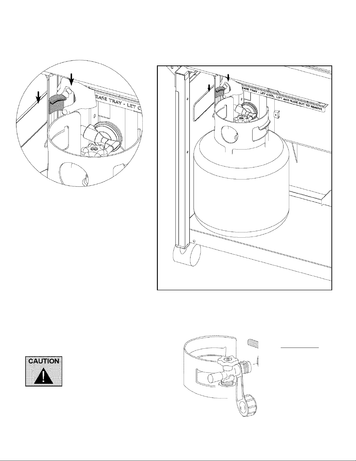
35. Place tank into hole located in bottom plate.
Insert Tank Bracket into Slot and rotate it 90 Degrees.
Slide bracket down over tank ring to hold tank in place.
36. Connect regulator with tank valve.
Be sure that hose assembly
does not contact the base
casting or any other parts
which will get hot.
/''m
■ ■■ :
24
Page 25
OPERATION
Warning: Before proceeding with
the following steps, ensure you
have read the L.P. Gas Cylinder
hose and Regulator sections of this
Assembly and Operation Manual.
Follow all directions under L.R Gas
Cylinder filling section of this
manual.
LIGHTING
Prior to lighting your grill,
visually check all hoses
before each use for nicks,
cracking, abrasions or cuts.
If the hose is found to be
damaged in any way, DO
NOT USE YOUR GRILL.
A replacement hose and
regulator is required (see
‘PARTS LIST’ in back of
book).
IMPORTANT
• Always raise the grill lid
before lighting.
• Do not lean over the grill
when lighting the burner.
• Visually check the flames
every time you light your
grill (Figure 8). If the flame is abnormally small or smokey
yellow -- shut off the grill and check the venturi tubes for
blockage (see Figure 11 on pg. 27) or refer to the
Troubleshooting Guide.
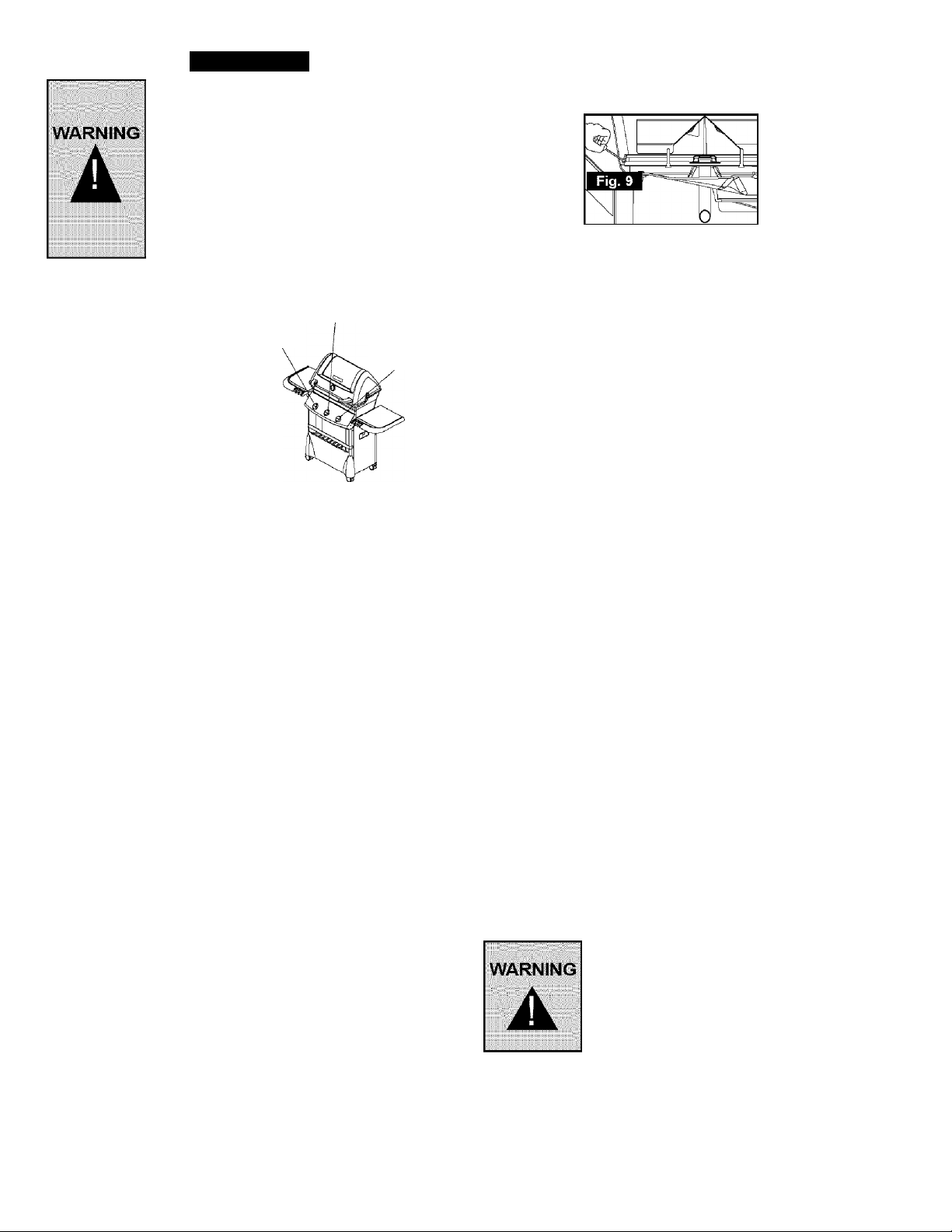
On grills with Three burners, the right control knob operates
the right burner, the left knob operates the left burner, and the
center knob operates the center burner.
Left Burner
Fig. 7
USING THE AUTO IGNITOR
Read these instructions before igniting.
1. Open lid during lighting.
2. Turn off all burners and close tank valve.
3. Open tank valve, wait 5 seconds.
4. Turn required burner knob to "IGNITE”.
5. You should hear a “clicking sound” indicating your electronio
ignition is activated.
6. If the burner does not light immediately (within four
seconds), turn burner control knob off and wait 5 minutes to
dear the gas.
7. Repeat steps 1 to 7. If burner still fails to light, refer to
Troubleshooting Guide to determine cause and solution,
or try the Match Lighting Procedure.
8. After grill lights, turn knob to desired cooking position.
MATCH LIGHTING PROCEDURE
TOpen the lid before lighting
2. Place an ignited lighter or lit match through the lighting hole.
(See Figure 9)
3. Push in and turn the LEFT burner control knob to ‘HIGH'.
The burner should light immediately (within four seconds). If
it does not, extinguish the lighter or match, turn the-control
knob to off, and wait 5 minutes to clear the gas.
Middle Burner
Right Burner
- HIGH
LOW
Fig. 8
4. Repeat steps 1 to 3. If burner fails to light, refer to the
Troubleshooting Guide to determine cause and solution.
5. Once left burner is lit push in and turn center burner knob
ffl^gh. Once it is lit, push in and turn right burner knob to
SIDE BURNER
1. Open L.P. cylinder.
2. Push in and turn the side burner control knob to “HI”.
3. Depending on which ignitor you have, turn or depress
ignitor. Repeat if necessary .
4. If burner does not light immediately (within four seconds),
turn the burner control knob off, and wait 5 minutes to clear
the gas.
5. Repeat steps 1 to 4. If burner still fails to light, refer to the
Troubleshooting Guide to determine cause and solution, or
try the Match Lighting Procedure above.
USING THE AUTO IGNITOR
1. Open tank valve, wait 5 seconds.
2. Turn required burner knob to
“IGNITE”.
3. You should hear a “clicking sound” indicating your
electronic ignition is activated.
4. If burner does not light immediately (within four seconds),
turn the burner control knob off, and wait 5 minutes to clear
the gas.
5. Repeat steps 1 to 5, if burner fails to light, refer to the
Troubleshooting Guide to determine cause and solution, or
try the Match Lighting Procedure above.
6. After grill lights turn knob to desired cooking position.
MATCH LIGHTING PROCEDURE
1. Place an ignited lighter or lit match near the ports,
approximately 1/2" (1.25 cm) from burner.
2. Push in and turn the side burner control knob to 'HIGH'. The
burner should light immediately (within four seconds). If it
does not, extinguish the lighter or match, turn the control
knob off, and wait 5 minutes for the gas to clear.
3. Repeat steps 1 and 2. If burner still fails to light, refer to the
Troubleshooting Guide to determine the cause and solution.
LOW HEAT OUTPUT
If the heat output from the burner(s) seems abnormally low.
It may be caused by the regulator flow-limiting device being
activated by a leak in the gas system, or improper lighting
procedures. If this is suspected, shut off the cylinder valve and
all burner valves. Perform a leak test to determine if a leak has
caused the flow-limiting device to activate. If the leak test is
negative, then carefully follow the lighting procedures step-by
step, ensuring all valves (including tank) are off before starting.
RELIGHTING
If the burner flame goes out when your grill
is in operation, immediately turn off the
control valves. Wait five minutes for the gas
to clear before attempting to relight the
burner. If the problem persists, refer to the
troubleshooting guide
SHUTTING DOWN YOUR GRILL
1. Shut off L.P. cylinder valve or natural gas main shut-off valve.
2. Shut off burner control valves.
This sequence prevents residual gas from being left in the
system under pressure.
25
Page 26

BREAKING IN YOUR GRILL
Before cooking on your gas grill for the first time, you should
"break it in" by operating it for a short period of time without any
food.
To "break in" your grill light the grill following the lighting
instructions as outlined on the console decal or in this manual,
(see page 25) . Close the lid and keep the temperature on
"HIGH" for 15 minutes. DO NOT OPEN THE LID DURING THIS
PERIOD. Then raise the lid and continue to operate your grill
on "HIGH" for an additional 5 minutes. Your grill is now ready for
cooking.
COOKING TECHNIQUES
PREHEATING THE GRILL
The cooking system and grids require heating prior to adding
food.
1. Light your grill as outlined in the ‘LIGHTING’ instruction
section.
2. Once lit, preheat your grill on the HIGH setting with the lid
down for 6 to 10 minutes.
3. Turn the burner control knobs to the appropriate heat
setting prior to adding your food. Preheating your grill is
not required when you are cooking food using the indirect
cooking or rôtisserie cooking techniques.
LID POSITION
Although keeping the lid up or down when cooking on your grill
is a personal preference, you will find that you will have fewer
flare-ups, and your food will cook in less time (therefore using
less fuel) if the lid is down. Keep the lid down when cooking
food that requires a long cooking period over a low flame, such
as when rôtisserie or indirect cooking.
WARMING RACKS
A warming rack may be included with your grill and provides
you with additional cooking space away from direct heat. This
is useful when cooking delicate items such as fish, boneless
chicken breasts or vegetables. Warming racks are also a great
place to keep food warm that is already done so you can serve
your entire meal at the same time.
Tip; AI ight application of cooking oil prior to use wil
keep food from sticking to the warming rack.
help to
CONTROLLING FLARE-UPS
Some flare-up during grilling is desirable to create the smoke,
which gives grilled food its unique flavor and appearance.
However, excessive flare-up can not only ruin your food, it may
lead to a dangerous condition as well. By excessively raising the
temperature within your grill, particularly if a build up of grease
in your grill ignites, these flare-ups may result in an uncontrolled
grease fire. Grease fires can occur if grease is allowed to build up
in your grill. Follow instructions for keeping your grill clean. Do not
leave grill unattended when burners are on, including warm-up
and burn-off periods.
In the event of a grease fire, turn burner valves off and close LP
tank valve.
DO NOT ATTEMPT TO PUT A GREASE FIRE OUT
WITH WATER.
DO NOT REACH OVER FLAMES TO OPEN OR CLOSE LID,
COOKING TEMPERATURES
HIGH Setting: Use the HIGH setting to preheat the grill, sear
meat such as steak, and to burn off any cooking residue from
the grids after cooking your meal. HIGH is rarely used for
extended cooking.
MEDIUM Setting: Most grilling or roasting of meat and
vegetables, as well as any baking, is best done at a medium
heat.
LOW Setting: A low temperature is used when cooking lean
meat or delicate items such as fish. All rôtisserie and smoke
cooking is done at low heat.
GRILL COOKING METHODS
Your grill is more than just a place to grill your burgers and
hotdogs - the possibilities are as endless as your imagination.
But, before you start experimenting, here are some frequently
used terms that will help:
Direct Cooking is also known as grilling. This is the most
popular cooking method and involves cooking food directly over
the flame, such as searing a steak. Other good candidates for
this cooking method are thin cuts of meat, vegetables, kabobs
and fillets.
Indirect Cooking means the food is cooked away from the
direct flame by placing it on the opposite side of the lit burner
and allowing the heat to tumble within the closed confines of the
closed grill, very similar to a convection oven. Much like your
oven, you can roast and even bake, provided your grill lid is
closed.
TO MINIMIZE FLARE-UPS:
• Trim excess fat from meats before cooking.
• Cook fatty meats on a low setting, or use the indirect
method described above.
• Ensure that your cooking system is free of excess
grease from previous usage.
• Check that the grease drain hole is not blocked.
• Cook with lid down to cut down on the flow of air.
• Reduce the heat settings.
26
Page 27
CLEANING & MAINTENANCE
To keep your grill working at its peak efficiency as well as
contribute to the safe operation of this unit, perform all of the
operations below at least once a year -- preferably at the start of
each cooking season.
AREAS TO TEST ON NATURAL GAS GRILLS:
• All hose connections
(see Figure 10C)
• All valve connections
(see Figure 10C & 10D)
PERFORM A LEAK TEST
A leak test ensures that there are no gas leaks prior to lighting
your grill.
WHEN A LEAK TEST MUST BE PERFORMED:
• Before lighting your grill for the first time.
• Every time the propane cylinder is refilled
• If any gas component is changed
• At a minimum once per season.
• After prolonged period of storage or non-use.
• If the regulator flow-limiting device has been activated.
The leak test should be performed in a well-ventilated area
away from any open flame, heat or ignition sources. DO NOT
USE A MATCH, OPEN FLAME OR SMOKE DURING LEAK
TESTING.
WHAT YOU’LL NEED
FOR TESTING:
1. A mixture of 50% liquid dish
soap and 50% water.
2. A brush or cloth to apply
the mixture.
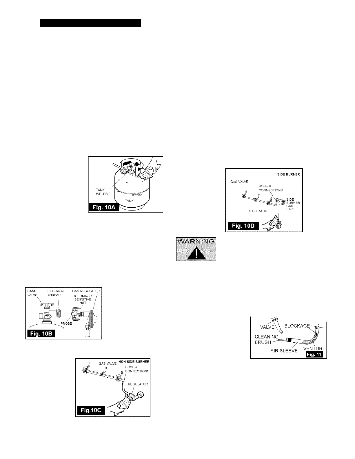
AREAS TO TEST ON PROPANE GRILLS:
• All propane cylinder welds (see Figure 10A)
• Propane cylinder valve — including threads into cylinder
(see Figure 10B)
• Regulator fitting and propane cylinder connection
(see Figure 10B)
•All hose connections (see Figure 10C) including side burner
tubing, if equipped (see Figure 10D)
• All valve connections
(see Figure 10C & 10D)
HOW TO DO THE TESTING:
IWith the grill console control knobs in the ‘OFF’ position, twist
the valve on your propane cylinder 1 turn, or the main natural
gas valve on.
PERFORMING THE LEAK CHECK.
2. Brush your soap and water solution on all connections and
components as outlined above.
3. Observe each place for growing bubbles, which indicate that a
leak is present.
4. Shut off the flow of gas while fixing the leak. Tighten
any leaking connection and repeat test until no leaks are
detected.
5. If the leak(s) cannot be stopped DO NOT USE Shut off the
fuel source at the valve immediately (if appropriate, remove
propane cylinder). Call a certified gas appliance service person,
or a gas dealer for proper repairs.
DO NOT IGNITE THE BURNERS WHILE
Failure to ensure the above may result in a
hazardous fire or explosion causing serious
bodily injury and/or property damage.
CLEANING VENTURI TUBES
Periodic cleaning of the venturi tubes is recommended for
optimum burner performance, especially after prolonged storage
or a period of non-use.
How to Clean:
• Remove the burner
(refer to ‘ASSEMBLY
PROCEDURE’)
• Use a venturi cieaning
brush, bottle brush or
stiff wire and insert
into the venturi tube
approximately 1 inch at a
time, removing after each
inch to prevent pushing any debris further into the tube,
(see Figure 11)
• As you remove the brush head inspect and discard any
debris
• Continue this procedure until the entire lengths of all venturi
tubes are free of debris
• Reinstall burner (as per assembly instructions), ensure the
venturi tubes are seated over the valve orifices
(see Figure 1)
• Perform a Leak Test.
CHECK TO ensure the burner
HAS A GOOD FLAME EACH TIME
27
IT IS TURNED ON.
Page 28
It is possible that very small insects could
make webs or nest in the venturi tubes. This
ii# will partially or completely block the flow of
g gas through the venturi and is indicated by
a smoky yellow flame, and/or a burner that
is difficult or impossible to light. Ultimately, it
may cause the gas to burn outside the venturis, which can
cause a fire resulting in damage to your grill and potential
personal injury. IF THIS HAPPENS IMMEDIATELY SHUT
OFF THE PROPANE AT CYLINDER, OR NATURAL GAS
AT MAIN SHUT-OFF VALVE. When the grill has cooled,
follow the "Cleaning Venturi tubes" steps
CLEANING OTHER PARTS OF YOUR APPLIANCE
BURNER:
At least twice a year, clean your burner when cleaning the
venturi tubes. The burner can be gently scraped dean with
a brass bristle brush. Ensure that all burner ports (openings)
are clear (DO NOT ENLARGE BURNER PORTS). If you find
cracks, abnormal holes, or damage caused by corrosion during
your inspection and cleaning, replace burner with appropriate
part as listed on the part list.
IGNITOR:
Clean the ignitor clip lightly using a wire brush to remove
rust and grease DO NOT USE WATER OR CLEAN THE
ELECTRODES. Visually inspect the ceramic of the electrode
for cracks. The electrode can be wiped with a soft cloth if
necessary. If a crack is found, a replacement ignitor system will
be required, look for O.E.M, ignition system or universal ignition
system.
CLEANING GRIDS:
After each use, scrub the cooking grids with a stiff long-handled
brass brush. Do not use steel brushes, as they can scratch the
nickel or porcelain coating. Grids can also be washed with mild
detergent. Never use commercial oven cleaners. If rust appears
on your cooking grids, remove the rust with a scrub pad and
coat the grid with some cooking oil. If excessive wear is evident,
you might want to replace or upgrade your cooking grid.
COOKING SYSTEM:
To clean your Heat Distribution Plate scrape it with a brass
bristle brush; clean using soap and water, then rinse and dry.
DO NOTALLOW EXCESSIVE GREASE OR OTHER RESIDUE
TO BUILD UP ON YOUR COOKING SYSTEM AS A FIRE MAY
RESULT.
SIDE SHELVES:
Metal Shelves: Use any household cleaner, except those
containing acid or mineral spirits. Be sure to rinse well after
cleaning. DO NOT USE AS A CUTTING BOARD.
Plastic Shelves and Panels: Clean with dish washing liquid, then
wipe dry, DO NOT USE AS A CUTTING BOARD.
COVER YOUR GRILL WHEN IT IS NOT IN USE TO PROTECT
THE SHELVES FROM THE OUTDOOR ELEMENTS.
GRILL EXTERIOR :
The white spots that may appear on the outside of the casting
are caused by the oxidation of the aluminum. This oxidation can
usually be removed with soap and water. If not, you can repaint
the outside casting using hi-heat grill paint.
GRILL INTERIOR, WARMING RACK:
At least once a year remove all components from inside your
grill. Loosen any cooking residue with a scraping tool for large
particles and a brass brush for smaller particles. Scrub with hot
water and a strong detergent, then rinse thoroughly or spray grill
degreaser liberally on all interior surfaces. Be sure to use gloves
and eye protection. Let stand for 10 minutes, scrape off residue
and repeat if required. Rinse thoroughly with water. Replace all
components as outlined in the assembly instructions.
USE DEGREASER ON PAINTED OR PLASTIC SURFACES.
DO NOT
GREASE TRAY:
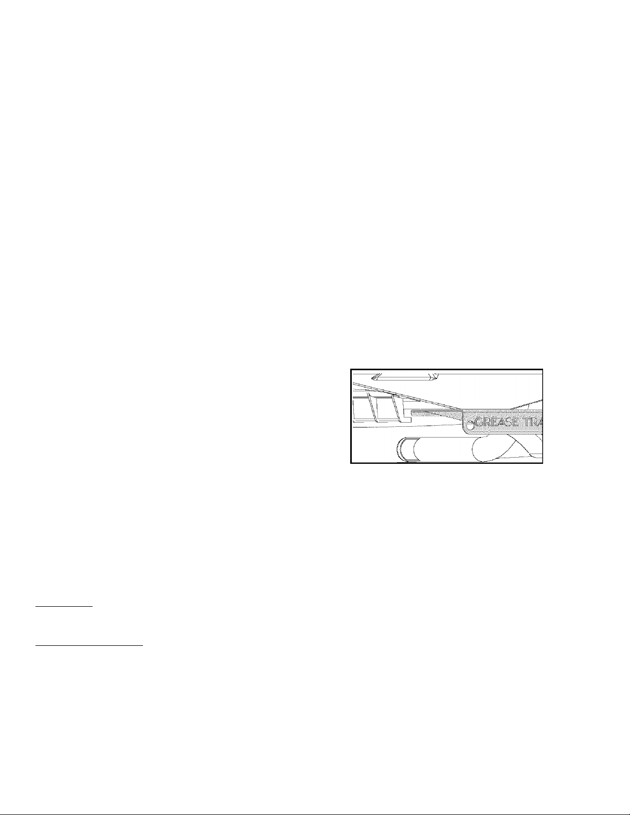
Your grill comes equipped with a tray for containing grease
that drips off your food. This grease tray can be accessed from
the rear of the grill just under the base casting. To remove the
grease tray, simply lift up on the tray and slide it out towards the
rear of the grill. To install the tray, guide the front edge of the
tray into the tray support rails and slide it in until the front lip of
the tray drops down over the front edge of the support rails
ALWAYS BE SURE THE TRAY IS COOL WHEN REMOVING
OR INSTALLING.
IT IS RECOMMENDED YOU CLEAN THE GREASE TRAY
BEFORE OR AFTER EVERY USE.
STORAGE
More people are discovering the pleasure of year round grilling.
However, if you choose to store your grill for the winter or any
extended length of time, follow these steps:
• Clean the cooking grids, then oil lightly with cooking oil, wrap
in paper and then store the cooking grids indoors.
• Follow the same cleaning method above for the burners and
any warming racks.
• Cover the grill if it is left outdoors.
• When the grill is not in use, the gas must be turned off at
the L.P. cylinder valve or main shut off valve, and stored
outdoors in a well-ventilated area.
With a Propane appliance you can store the grill inside,
PROVIDED the cylinder is removed from the grill and
stored outdoors in a well-ventilated area, out of the reach of
children. When the cylinder is disconnected from the grill,
ensure the cylinder valve safety cap is firmly in place.
After a period of storage or non-use, a leak test should be
performed and the burner venturis cleaned prior to use.
28
Page 29
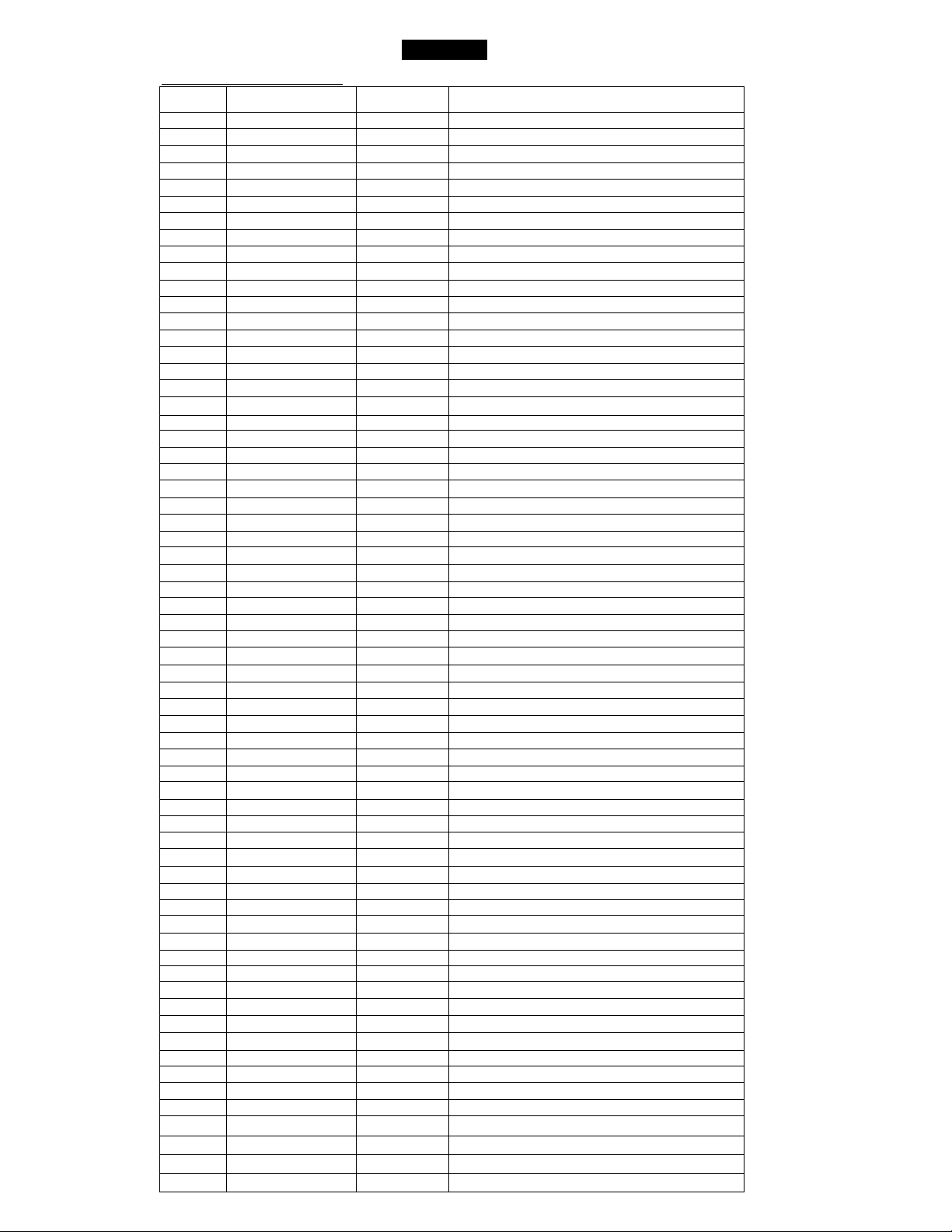
Kenmore Propane Gas Grill
REF# PART#
1.
2,
3.
4,
5.
6,
7.
8.
9.
10.
11.
12.
13.
14.
15.
16.
17.
18.
19.
20.
21.
22.
23.
24.
25.
26.
27.
28.
29.
30.
31.
32.
33.
34.
35.
36.
37.
38.
39.
40.
41.
42.
43.
44.
45.
46.
47.
48.
49.
50.
51.
52. SP5037-6 4
53.
54.
55.
56.
57.
58.
59.
60.
61.
62.
63.
64.
SP5051-26
SM5006-1L 1
SP5002-30 1
SP5028-19 1
SP5003-16 2 Knurl Nut
SP5029-19 1
SP5000-16 2 Wino Nut
SP5000-17 2 Washer
SM5054-42 1
SP102A-3G 2
SP18-16 4
SP5024-20 1
SP5000-40 3 Spacer
SP5026-20 1
SP5027-20 2
SP5034-9
SP5006-16 3
SM5036-9W 1
SP5092-12 3
SP25-16 2 Wino Nut
SM5001-2L 1
SM5060-9E
SM5045-9E 1 Box Shelf
SP5012-18 3 Carriage Bolt
SP5012-16 8
SP5003-22 2
SM5023-6E 2
SM5024-6E 2
SM5064-9E 2
SM5243-42E 1
SP5023-18 8 Carriage Bolt
SP5035-6N
SP5025-9E 1
SP5000A-20 1
SP5000-7 4 Knob
SP21-6 1
SM5024B-9E 1
SP5030-4 1
SP5002-22 2
SP5001-33 4 Caster Insert
SM5272-42E 1
SP5013-15 2
SM5242-42E 1
SM5032-19E
SP5055-9 1
SM5056-9E 1
SM5273-42E 1
SM5046-9E 1
SP5005-15 1
GG20-27 1
SP5014A-3 1 Warming Rack
SP5018-18
SP5094-12 1
SP135-3 1 Side Burner Cooking Grid
SP5019-18 2
SP5031-9 1
SP5007-16
SP5006-20
RM5038-6F 1
SP5032-20
SP15-21
SP5021-18
SP2-16
Part List
QTY DESCRIPTION
1
1
1 Left Hand Shelf Trim
1
1
24
2 #6-32 Wing Nut
1
1
2
2
2
Logo
Lid
Temperature Gauge
Left Hand Handle End
Right Hand Handle End
Handle Tube
Cast Iron Cookina Grid
Wino Nut
Cross Lighter Top Plate
Cross Liahter Bottom Plate
Electrodes
Heat Distribution Plate
Knurl Nut
Grease Trav
Burner
Base Casting
1/4-20 Wing Nut, Clear Zinc
Locking Caster
Shelf Support Bracket A
Shelf Support Bracket B
Side Panel
Left Leg Assembly
Front Panel Strap
Front Panel
Ignitor Module
Tank Clio
Bottom Plate
Manifold Assembly
Non LockinqCaster
Console Assembly
Push Pin
Right Leg Assembly
Side Burner Lid Handle
Burner Tray
Side Burner Lid
Right Hand Shelf Trim
Side Burner Base
Hinge Clio
Tank fNot Includedt
Bezel
#10 X 1/2 Phillips drive screw
Side Burner
Shoulder Screw
Lid Overlay
Ground Wire
Back Support
Switch Harness
#8 X 3/8 Tapping Screw
1/4 -20 X 1/2 Carriage Bolt
1/4 - 20 X 1/2 Wingnut, Black
29
Page 30
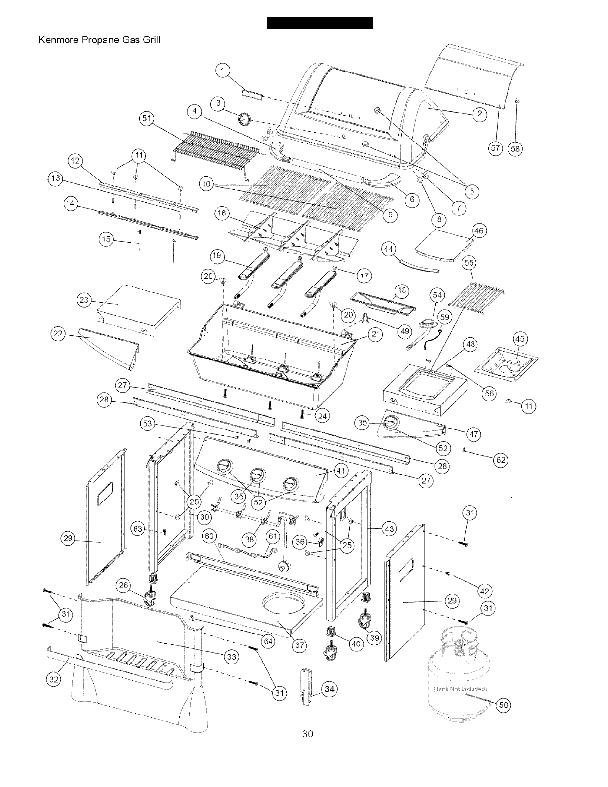
EXPLODED VIEW
Page 31
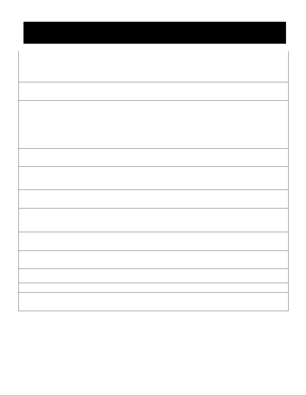
TROUBLESHOOTING GUIDE
IF YOU ARE EXPERIENCING DIFFICULTY AFTER FOLLOWING THIS GUIDE, PLEASE CONTACT OUR
CUSTOMER SERVICE TOLL FREE - PHONE 1-800-396-3838 OR FAX 1-615-441-2941.
1. Burners will not light. Out of propane? Is venturi properly seated over orifice? Inspect both venturis and
burner holes for obstructions. Check ignition spark. Is cylinder valve turned on?
Regulator assembly not fully tightened to cylinder valve? If you have electronic
ignitor, is the battery good?
2. Flame burns out on
"Low"
3. Burners are not hot enough
4. Flame smokey yellow. Check to see if burners and venturis are clean (See page 27). Check for
5. Console Fire (Flame
coming up venturi around
console /control knobs).
6. Grease dripping from base
7. Regulator Humming.
Has grill been sufficiently preheated before turning to "Low"? Is venturi properly
seated over orifice? Inspect both venturis and burner holes for obstructions.
Your grill is equipped with a flow limiting device intended to reduce the flow of
gas in the event of a leak. This device can also be activated if you do not follow
the correct lighting procedure. Follow proper lighting sequence (see page 25) or
correct leak in system (see page 27) as instructedJnspect venturi, orifice, burner
holes and heat control valves for obstructions and alignment. Make sure burners
and heat distribution system (heat distribution plates, lava rock, briquettes or tiles)
is clean.
proper air shutter opening in venturis.(Side Burner Only)
Immediately shut off gas supply at tank valve. Allow grill to cool.
Remove burners and check venturis and orifices for obstructions.
Is grease tray properly installed? Is it full of grease? Check to ensure bolts are
tight, washers are in place. Check that Grill is level.
This is not a defect or hazard. The noise is internal and caused by cold propane
passing through a restricted passage.(Usually with a full tank in hot weather. This
will subside after a short period of operation)
8. Burner lights with match,
not with ignitor.
9. Too much heat. Excessive grease build-up ("Grease fire"). Damaged or missing orifice. Faulty
10. Excessive flare-up.
11. Incomplete burner flame
12. Propane tank will not fill. If during filling, the overfill protection device (O.P.D.) trips prior to tank being full,
Broken wire or electrode. Defective ignitor or switch. Obstructions in venturi. If
you have electronic ignitor, is the battery good?
regulator. Restricted heat flow through grill.
Reduce temperature. Clogged grease drain. Overload of fatty meat. Close lid to
contain flare up.
Plugged, leaking or rusted burner.
invert tank briefly to reset O.P.D.
31
Page 32

Get it fixed, at your home or ours!
Your Home
For repair-in your home -of all major brand appliances,
lawn and garden equipment, or heating and cooling systems,
no matter who made it, no matter who sold it!
For the replacement parts, accessories and
owner’s manuals that you need to do-it-yourself.
For Sears professional installation of home appliances
and items like garage door openers and water heaters.
1-800-4-lVlY-HOME ® (1-800-469-4663)
Call anytime, day or night (U.S.A. and Canada)
www.sears.com www.sears.ca
Our Home
For repair of carry-in items like vacuums, lawn equipment,
and electronics, call or go on-line for the location of your nearest
Sears Parts & Repair Center.
1-800-488-1222
Call anytime, day or night (U.S.A. only)
www.sears.com
To purchase a protection agreement (U.S.A.)
or maintenance agreement (Canada) on a product serviced by Sears;
1-800-827-6655 (U.S.A.) 1-800-361-6665 (Canada)
Para pedir servicio de reparación
a domicilio, y para ordenar piezas:
1-888-SU-HOGAR
(1-888-784-6427)
Au Canada pour service en français:
1-800-LE-FOYER
(1-800-533-6937)
www.sears.ca
® Registered Trademark / ™ Trademark / Service Mark of Sears, Roebuck and Co.
® Marca Registrada / Marca de Fábrica / Marca de Servicio de Sears, Roebuck and Co.
Marque de commerce / “° Marque déposée de Sears, Roebuck and Co.
) Sears, Roebuck and Co.
 Loading...