

Ilm#mkmd mmdbk*,e
TIT I AT R
Straight Stitch Attachment Zigzag Bite I_t Control
Position Dimension
i i II III
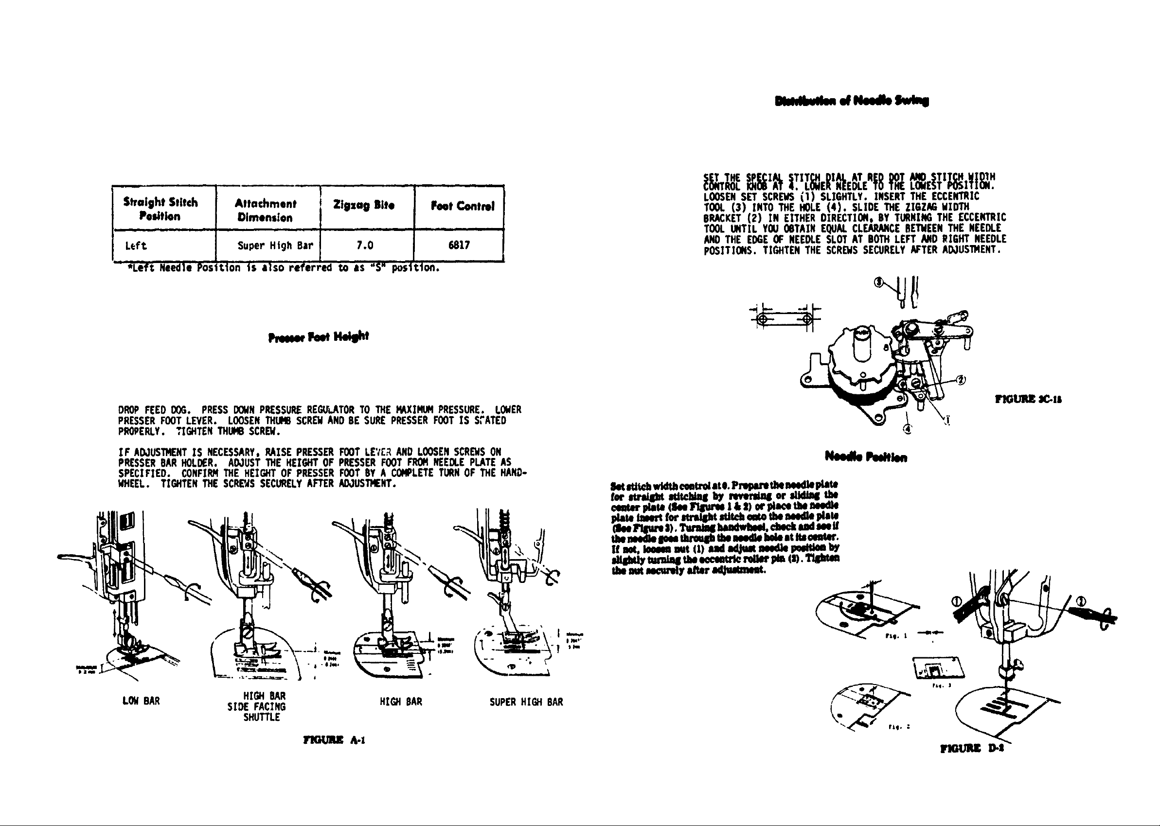
Left Super High Bar 7.0 6817
' *Left Needle Pos ttonts _t]so referl:ed to as "S" pos ;ton.
pmoeh,t.,
DROP FEED ODG. PRESS DOMNPRESSUREREGtft.ATORTO THE _XINUtl PRESSURE. LOWER
PRESSERFOOTLEVER. LOOSENTHLIHBSCRENAND BE SURE PRESSERFOOT IS S:'ATED
PROPERLY. TIGHTEN THUMBSCREW.
IF ADJUSTMENTIS NECESSARY,RAISE PRESSERFOOT LETr_ AND LOOSENSCREWSON
PRESSERBARHOL_R. ADJUST THE HEIGHT OF PRESSERFOOT FROMNEEOLEPLATEAS
SPECIFIED. CONFIRMTHE HEIGHT OF PRESSERFOOT BY A COMPLETETURNOF THE HAND-
WHEEL. TIGHTEN THE SCRE'_SSECURELYAFTER N_IUSIMENT.
LOOSENSET SCRENS(i) SLIGHTLY. INSERT THE ECCENTRIC
TOOL (3) INTO THE HOLE (4). SLIDE THE ZlGZkG WIDTH
BRACKET(2) IN EITHER DIRECTION, BY TURNING THE ECCENTRIC
TOOL UNTIL YOU OBTAIN EQUAL CLEARANCEBETMEENTHE NEEDLE
AND THE EDGEOF NEEDLESLOT AT BOTH LEFT AND RIGHT NEEDLE
POSITIONS. TIGHTEN THE SCREMSSECURELYAFTERADJUS1MENT.
IqGUI_ X:.ls
NeedleP_thm
LON BAR
HIGH BAR
SIDE FACING
SHUTTLE
HIGH BAR SUPERHIGH BAR
o.o
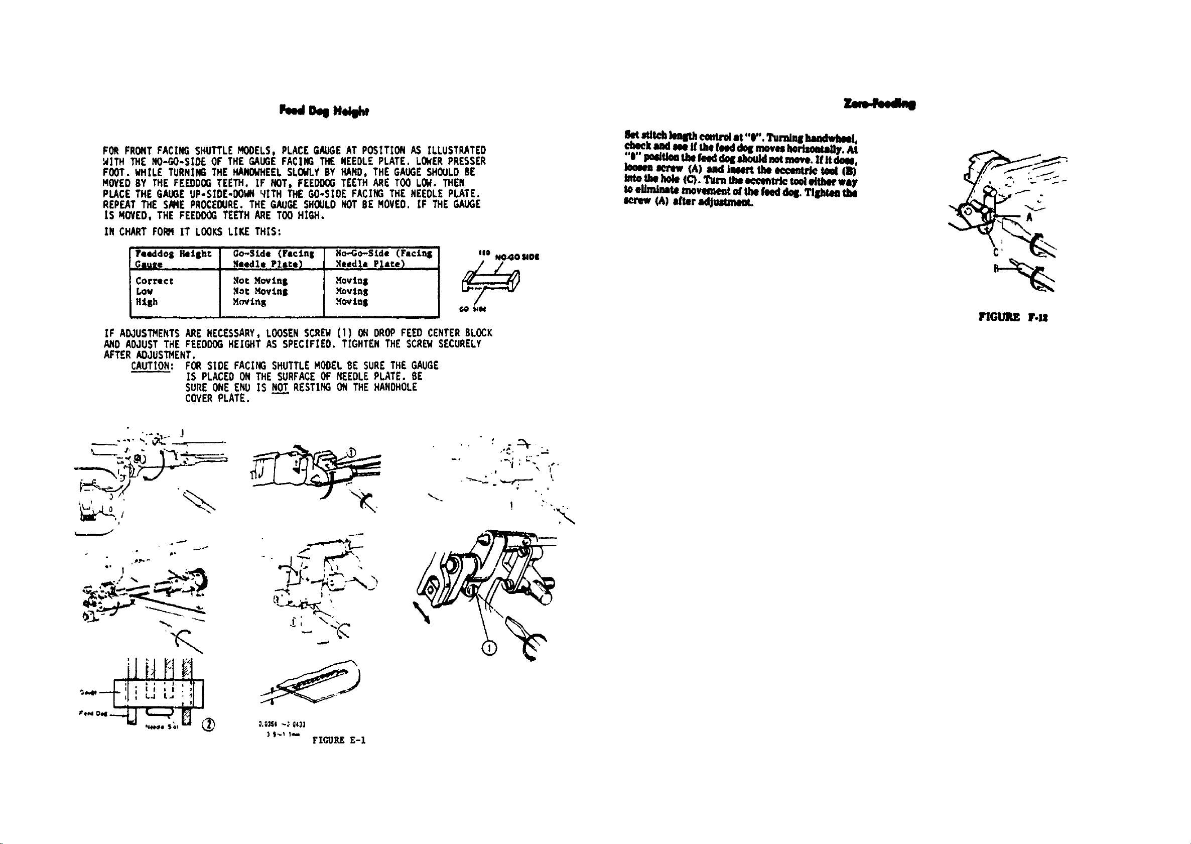
FOR FRONTFACING SHUTTLEMODELS, PLACE GAUGEAT POSITION AS ILLUSTRATED
'AITH THE NO-GO-SIDE OF THE GAUGEFACING THE NEEDLE PLATE. LOWERPRESSER
FOOT. HHILE TURNING THE HANOWHEELSLOWLYBY HAND, THE GAUGESHOULDBE
MOVEDBY THE FEEl)DOGTEETH. IF NOT, FEEDOOGTEETH ARE TOOLOH. THEN
PLACE THE GAUGEUP-SIDE-OOHN '_ITH THE GO-S[DE FACING THE NEEDLEPLATE.
REPEATTHE SAMEPROCEDURE.THE GAUGESHOULDNOTBE HOVEO. IF THE GAUGE
IS qOVED, THE FEEDOOGTEETH ARE TOO HIGH.
IN CHART FOI_4 IT LOOKSLIKE THIS:
[Feeddo$ Ikelsht Go-Side (Fecins No-Go-Side (Faclnl_
Gsu2e NHdle Plste_ _eedle,,Place)
Lov
RtEh
IF AOJUSTHENTSARE NECESSARY,LOOSENSCREH (1) ON DROPFEEO CENTERBLOCK
AN0 ADJUST THE FEEDDGOHEIGHT AS SPECIFIE0. TIGHTEN THE SCREHSECURELY
AFTER AOJUSTHENT.
CAUTIO_____N:FOR SIDE FACING SHUTTLEMODELBE SURETHE GAUGE
[S PLACE0 ON THE SURFACEOF NEEDLEPLATE. BE
SURE ONEENU IS HO_T.TRESTING ON THE HAHOHOLE
COVERPLATE.
Hot Novtn$
Mot Hovtn$
Movtn8
._ovtnS
HoVLnll Go_H
lk_ _t_ lenlPh_"a_-d at "0". l_rni_ hancheheeL
'-'hockMd He ff thefNd dol_movu IsorisoetaHy.At
"O"Poiltk_ tla fe_l dot shouldad laove, if it d_a,
Iomm aerme (k) add imert the eeeoaSrletool _)
Imo II_ hol_ (C) •Turn U_ o¢._nlrle I_I Mtbo_way
toelJminaUimovementof the feeddoll Tlshtm the
screw (A) after _lJussmem.
FIGURE F.IS
.o
• ':_L-'__ _/,,--_'.
_ __-r-
B-
-r..
' "" 'II
,...o.,
_ | .
0.01SO-} 04_l
e
.. . .£_ .
! ,".
._)
\
FIGURE E-I

Needle Timlql te Shuttle
.dq Shv
/hr H,k
(INSTRUCTION FOR RAOIAL TIMING GAUGE)
USE IOURCEIU .FRONT?JISFRONTTJO HDURCE|iIO ,FRONTli.I |FRONT4.11 IOURCE1H
GAUGE $10E4,1
USE • FRONT 7.0 $ FRONT 7JO • FRONT SJ | FRONT4,0
MARK
I|1 10eeO 341 Fm Stmllle
lU 11041 103O0 343 Mod*ll
lee 17010 103Ol 33O
120 17011 10302 121
m 17012 103O4 U2
Nil 1103O 10400 See
922 17031 17741 12010 10401 640
_14 17002 13OEO 1O4O2 041
17000 17033 131110 10430 143
I_001 17011 13180 10140 113O
17490 18011 13180 101144 182
1_$10 11020 13100 liH_I0 3O0
13oI0 11021 901
m
10130 17900 _0
10101 17S70
11143, 17S71 =
m4_ 170TZ am
11143_ 17740 12110
11140 1111119 10941 841
lW
13o22
13o_
13o_4
18o3o
13o_11
13o_
10033
16O34
1M3o
10131
1_00
131101
1321O
lee3o
1M70
13471
leelO
1_1
14W0
14001
14402
14O03
14100
14101
143OO
143O1
14310
14311
11144
1B1EO
13100
13O01
10010
13011
13o1|
14_10
11021
1E210
1L1M
18410
1143o
leO0
14310
10000
10040
1720O
1T3O4
17110
171H;0
17001
11113O
1_3O
11_10
1Mll
• 19400
1N10
19411
1Mll
1_40
19441
11470
19471
3O2
3O3
144
3ON
18000
'_lOdell v_n,¢n _ ntst olive I center needle ;)oSitlOl for
$tri_t stltctting must _e f41 to the canter position _4fore
Jslng thl rid,ld tlmln 9 gauge If the '.ow air Al,nment
Gauge ,s av4,11Oie, the following method rely _1 use,*.
F,rst. insert ",Hi pin with blunt t'O ar_ tigtltefl needle
¢14m0 I¢tt, w securelv Place p4ttesn d_ numUer 1081
18. or r_mber 26842 (acc_tdm 9 to the model) onto the
cam dr_ver mlft and turn ,t i_v hind until the cam follower
12) to_llel the Cam s_rface at the mixiff%lm dUlm•ter of
thll dilx_. On models thet hey• th4 Sse41d_d ,TIHtt l:_ilt in.
set the s_el StitCh di_l to the '_°' _boa.
Rem_:rve .the prester foot and Ittech the tow g4r Align.
merit Gauge oato the _resser b4r. LeVite center needle
Position 0Y rot4tmg stitch width c_ttrol until the test
Om €omes to t1_e C hole on the gluge I_ 1hewn. Confirm
tett ;)in _s,n C hole, raise the needle bit t)v rotating h_ld.
wheel, remove me geuge.
Check ttle rldii! timing and needle _lr height follo_nQ
th• instructions dnder G,3.
FIOURE 64
zi q
Set stitch wld_ eoatrol at maxLmum. 'rumin8 the
Imadwl_el. cl_lek Ind m if the needle lid• moUon
oa the stMdlrd pllme (0._414inch above the upper
lit/ace el Ull needle phlte) at botliillll_tl polliUolli
eon_, within the enllineerLol limit el 0.0131Lacb. I!
aot, _ set screw (2) on _e worm sear elUaer
dlre,..Uon. Tl|lht_ the screw (2) lecurely slier
lldJulltnlent.
The redi81 timing ghulPs and telt plflS,el |iluStrot4(I below, Me ev|ilible through Oep4rtment 20a, _RJI9o only. The kit
isidentified N _.
/
. ,,, .t .. \
i,"" <.l.J \
,.
l: O,OI ll" (O._O_i F'tGI H_

StraightStitch
Pedtkm
REJ40VEAI_4 COVER. SET STITCH WIDTH CONTROLAT RED S OR
DOT. CHECKTO SEE IF THE NEEDLE SWINGSBY MOVING ZIGZAG
GUIDE BASE (C) IN EITHER DIRECTION AS SHOgN. NEEDLE
SHOULDNOT SWING. IF AO,JUS'ff4ENTIS NECESSARY.LOOSEN
SCREW(A). HOLD ZIGZAG GUIDE BAR (O) DOHI_AROSLIGHTLY.
SET STITCH wIDTH CONTROL(B) AT RED S OR DOT ANDTIGHTEN
SCREW(A).
C
D
B
A
?IGUREI-9
0

Avlwm_ Mechee4m
CamendCemfeJlewerMechenlem
kme.mkrevue,Semkkq
hlmdude
If the le_Msbof mverne 84ttebm JsJhortor or ioqer
_ or cumer.dedtwiN, _ you €_n oeunn
Iiw arts_t lmbwce.
Set zJIBI width _ at 4, special stitch dhd at
], Jtlt_ le_l_ m_ it I 8_1Jpe_ll stitch WJl
at middle p_tton between S t_l L. Place m
pathn'n _m into the nuJch_e_i U a i_ttUn'ndi_
_orr_ pattern (u JUum'at_). J_Uwt
themacb_ in the toilowin8 waT. Lowensets_'ew
(1). lwer_ e_%*enurictool (2) LMotheho_e($) andt_m
the tad to either _ (dodmlN or €ouator-
(dockwiM) to move the phKe (4) as WuJtI"shKL
?tShUm t_e s_rew (1) Ncur_ alter adjustment.
FIGURE J-tlA
M limit o1101_111 lU=_m _,.._l--. ,mill v0U
(RI €_IocI_eto41or €_Jlnm"cmmLwmm, ---" -+..
am---_In +dSeax'rect MIsnCe.Tllhten Wenut t^+
jdwrj4jwunent.
FIGUIUE J-IIB
Cam Selector Guide Plate Setting
_It Stlt_9_ llnqtll dill It + Ind 51_41€1115t, t¢_ dill •€ "S" or
rld dot. Thl cam follOW4_f _1ould align _ith • C•m ii shOWn
If not, loosen nut !A). and turn lC¢lntr_€ screw (l_l sl+_jdltly
tO 411thlt dirlction (countlrclockw_s4 or <:lockw_Se) SO that
thl fOIlOWt_' aligns w_th ,1 jm. Ti_lhten n_1 tA_ SIl_'+Jfe_
aft•r adjustment.
X _oo<1 X
Pattern
A
F_GUK_,_-S
 Loading...