

TABLE OF CONTENTS
[ Knowing Your Sewing Machine
identifying Parts ............................. 1,2
Installing Machine .............................. 3
Winding the Bobbin ........................... 4
Threading the Bobbin Case .................. 5
"[hreading of Top Thread ..................... 6
Using the Controls
Top Tension Control .................... 7.8
Adjusting Bobbin Tension .................. 9
Checking Tensions ....................... 10
Stitch Length Control ,,: ............... 1t 12
Stitch Width Control .................. l t, 12
Reverse Stitch Control .................. 11. t2
Special Stitch Variegator .................. ', t
Metal Cam .................................. |3
Special Stitch Dial ................... 14.15, 16
Pressure Regulator ........................ | 7
Feed Dog Control ...... •.................... t8
Sewing Light................................. 18
Multi Purpose Needle Plate ............... 19
Accessories
Needles ................................ 20 21
Presser Feet ................................ 22
Buttonhole Attachment .................... 23
]_ Starting to Sew ............................ 24
Garment Construction Stitches
Straight Stitching .......................... 25
Zigzag Stitching ........................... 26
Chain Stitching ............................. 27. 28
Stretch Stitching ............. 29 30.3t 32
Special Finishing Stitches
Satin Stitching ............................. 33
Buttonhole Making ....................... 34
Appliqueing °;. .............................. 35
Blind. Hemming ....................... 35.36
_[ Checking Performance Problems .... 37, 38
Hints on Sewing on Different Fabrics 39.40
p/" Caring for the Machine
Cleaning Feed Dogs end Shuttle ........ 42
Oiling Under Arm Cover Plate ........... 43
Oiling Underside ........................... 44
Oiling in Face Cover Plate ................. 44
Parts List ................................. 45.46
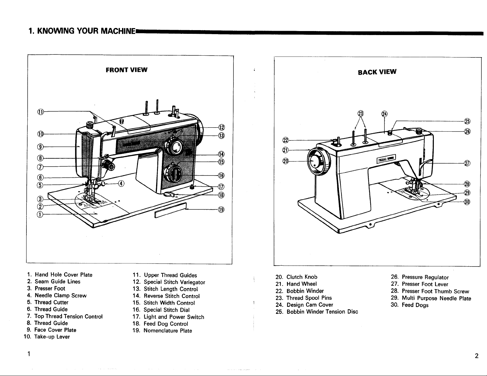
1. KNOWING YOUR MACHINE-
@
@
®
®
®
®
FRONT VIEW
BACK VIEW
@
@
.@
@
.@
1. Hand Hole Cover Plate
2. Seam Guide Lines
3. PresserFoot
4. Needle Clamp Screw
5. Thread Cutter
6. Thread Guide
7. Top Thread Tension Control
8. Thread Guide
9. Face Cover Plate
10, Take-up Lever
11. Upper Thread Guides
12. Special Stitch Variegator
13, Stitch Length Control
14. Reverse Stitch Control
15, Stitch Width Control
16. Special Stitch Dial
17. Light and Power Switch
18. Feed Dog Control
19. Nomenclature Plate
20. Clutch Knob
21. Hand Wheel
22. Bobbin Winder
23. Thread Spool Pins
24. Design Cam Cover
25. Bobbin Winder Tension Disc
26. Pressure Regulator
27. Presser Foot Lever
28. Presser Foot Thumb Screw
29. Multi Purpose Needle Plate
30, Feed Dogs
2
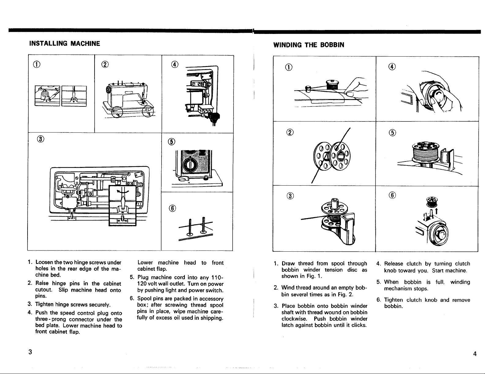
INSTALLINGMACHINE
WINDINGTHEBOBBIN
®
® ®
®
®
®
®
®
®
/
®
i
I,
Loosenthe two hinge screws under
holes in the rear edge of the ma-
chine bed.
2. Raise hinge pins in the cabinet
cutout. Slip machine head onto
pins.
3. Tighten hinge screws securely.
4. Push the speed control plug onto
three-prong connector under the
bed plate. Lower machine head to
front cabinet flap.
Lower machine head to front
cabinet flap.
5. Plug machine cord into any 110-
120 volt wall outlet. Turn on power
by pushing light and power switch.
6. Spool pins are packed in accessory
box; after screwing thread spool
pins in place, wipe machine care-
fully of excess oil used in shipping.
1. Draw thread from spool through
bobbin winder tension disc as
shown in Fig. 1.
2. Wind threadaroundanempty bob-
bin severaltimesas in Fig.2.
3. Place bobbin onto bobbin winder
shaft with thread wound on bobbin
clockwise. Push bobbin winder
latch against bobbin until it clicks.
4. Release clutch by turning clutch
knob toward you. Start machine.
5. When bobbin is full, winding
mechanism stops.
6. Tighten clutch knob and remove
bobbin.
4

THREADINGTHEBOBBINCASE THREADINGOFTOPTHREAD
®
®
®
Fig. 1
®
1. To remove bobbin from the shuttle,
raise needle to its highest position.
Remove hand hole cover plate.
2. Pull open latch of bobbin case.
3. Pull bobbin case straight out of
shuttle.
4. Insert bobbin into bobbin case
making sure thread is coming
from bobbin as shown.
5. Pull thread through slot of case
as shown.
®
\
r
6. Pull thread under tension spring.
7. Holding latch open, position case
into shuttle, and release latch. Case
should lock into place when latch
is released.
8. Hold needle thread loosely in left
hand and rotate hand wheel toward
you one complete turn. Bring bob-
bin thread up by pulling upper
thread.
Place thread on spool pin as shown
with thread coming from the back of
the spool. Draw thread through the
top thread guides. Holding the spool
stationary with right hand, pull the end
of the thread between the tension discs
as shown. Pull the spring wire loop up
and past the top hook until the thread
Fig. 2
;__ Fig. 3
can be slipped into the hook (See Fig.
1). When the thread is released, the
spring wire loop will return to position
(See Fig. 2) with thread in proper
place. Release spool of thread and
continue to thread machine exactly as
shown. Needle mustalways be thread-
ed in direction as shown in Fig. 3.
5 6
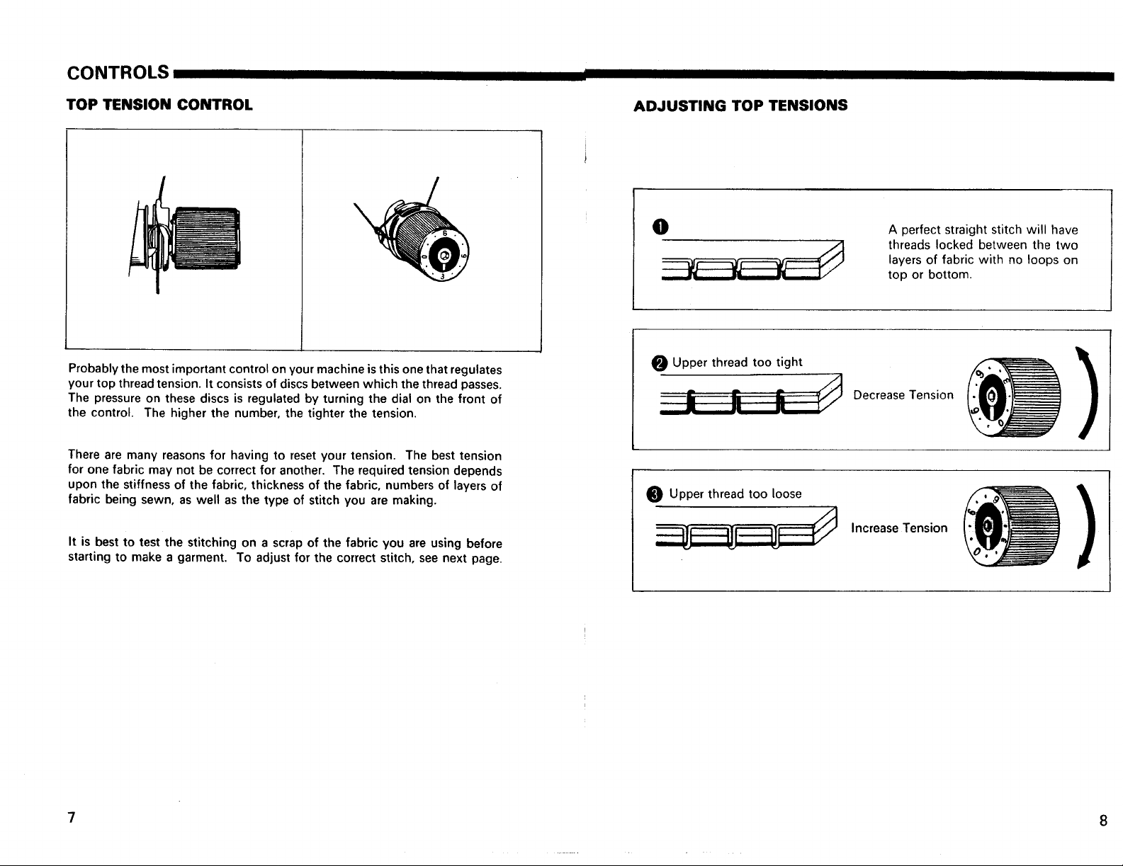
CONTROLS
TOP TENSION CONTROL
Probably the most important control on your machine is this one that regulates
your top thread tension. It consists of discs between which the thread passes.
The pressure on these discs is regulated by turning the dial on the front of
the control. The higher the number, the tighter the tension.
There are many reasons for having to reset your tension. The best tension
for one fabric may not be correct for another. The required tension depends
upon the stiffness of the fabric, thickness of the fabric, numbers of layers of
fabric being sewn, as well as the type of stitch you are making.
ADJUSTING TOP TENSIONS
O
0 Upper thread too tight
/I
t_ t. -
" I! =, t/
Upper thread too loose
A perfect straight stitch will have
threads locked between the two
layers of fabric with no loops on
top or bottom.
Decrease Tension
It is best to test the stitching on a scrap of the fabric you are using before
starting to make a garment. To adjust for the correct stitch, see next page.
7
Increase Tension
ADJUSTING BOBBIN TENSION,
CHECKING TENSIONS
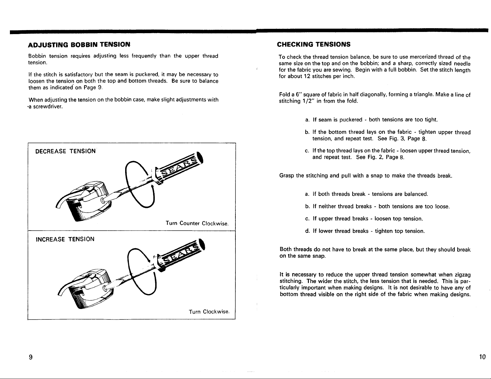
Bobbin tension requires adjusting less frequently than the upper thread
tension.
If the stitch is satisfactory but the seam is puckered, it may be necessary to
loosen the tension on both the top and bottom threads. Be sure to balance
them as indicated on Page 9.
.
When adjusting the tension on the bobbin case, make slight adjustments with
•a screwdriver.
DECREASE TENSION
Turn Counter Clockwise.
INCREASE TENSION
To check the thread tension balance, be sure to use mercerized thread of the
same size on the top and on the bobbin; and a sharp, correctly sized needle
for the fabric you are sewing. Begin with a full bobbin. Set the stitch length
for about 12 stitches per inch.
Fold a 6" square of fabric in half diagonally, forming a triangle. Make a line of
stitching 1/2" in from the fold.
a. If seam is puckered - both tensions are too tight.
b. If the bottom thread lays on the fabric - tighten upper thread
tension, and repeat test. See Fig. 3, Page 8.
c. If the top thread lays on the fabric - loosen upperthread tension,
and repeat test. See Fig. 2, Page 8.
Grasp the stitching and pull with a snap to make the threads break.
a. If both threads break - tensions are balanced.
b. If neither thread breaks - both tensions are too loose.
c. If upper thread breaks - loosen top tension.
d. If lower thread breaks - tighten top tension.
Both threads do not have to break at the same place, but they should break
on the same snap.
It is necessary to reduce the upper thread tension somewhat when zigzag
stitching. The wider the stitch, the less tension that is needed. This is par-
ticularly important when making designs. It is not desirable to have any of
bottom thread visible on the right side of the fabric when making designs.
Turn Clockwise.
9 10
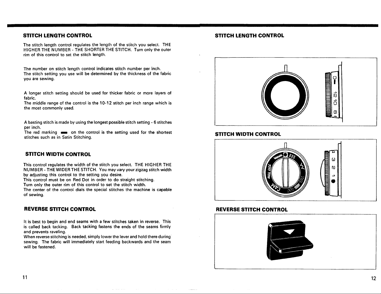
STITCH LENGTH CONTROL
The stitch length control regulates the length of the stitch you select. THE
HIGHER THE NUMBER - THE SHORTER THE STITCH. Turn only the outer
rim of this control to set the stitch length.
The number on stitch length control indicates stitch number per inch.
The stitch setting you use will be determined by the thickness of the fabric
you are sewing.
A longer stitch setting should be used for thicker fabric or more layers of
fabric.
The middle range of the control is the 10-12 stitch per inch range which is
the most commonly used.
A basting stitch ismade by using the longest possible stitch setting - 6 stitches
per inch.
The red marking m on the control is the setting used for the shortest
stitches such as in Satin Stitching.
STITCH WIDTH CONTROL
This control regulates the width of the stitch you select. THE HIGHER THE
NUMBER - THE WIDER THE STITCH. You may vary your zigzag stitch width
by adjusting this control to the setting you desire.
This control must be on Red Dot in order to do straight stitching,
Turn only the outer rim of this control to set the stitch width.
The center of the control dials the special stitches the machine is capable
of sewing.
STITCH LENGTH CONTROL
STITCH WIDTH CONTROL
REVERSE STITCH CONTROL
It is best to begin and end seams with a few stitches taken in reverse. This
is called back tacking. Back tacking fastens the ends of the seams firmly
and prevents raveling.
When reversestitching isneeded, simply lower the lever and hold there during
sewing, The fabric will immediately start feeding backwards and the seam
will be fastened.
REVERSE STITCH CONTROL
11 12
SPECIAL STITCH VARIEGATOR SPECIAL STITCH DIAL
There are certain types of utility stitches you will use often in your home
sewing. This control enables you to just dial the stitch you need for the
task at hand.
All stitches printed in red on the dial must be sewn with the Special Stitch
Variegator set at the Red Dot.
This control determines the feed of the feed dogs. All _imple forward stitcl_es
require that this control be set at the red dot. These stitches are the
straight stitch, zigzag, mending, blind hem, and basic decorative desig,n_
Stretch stitches and reverse stitch designs are made by setting the Special
Stitch Variegator to point to the white and green dots or adjusted slightly
toward the white arrow head mark above the dots. See next section for
specific settings for individual stitches.
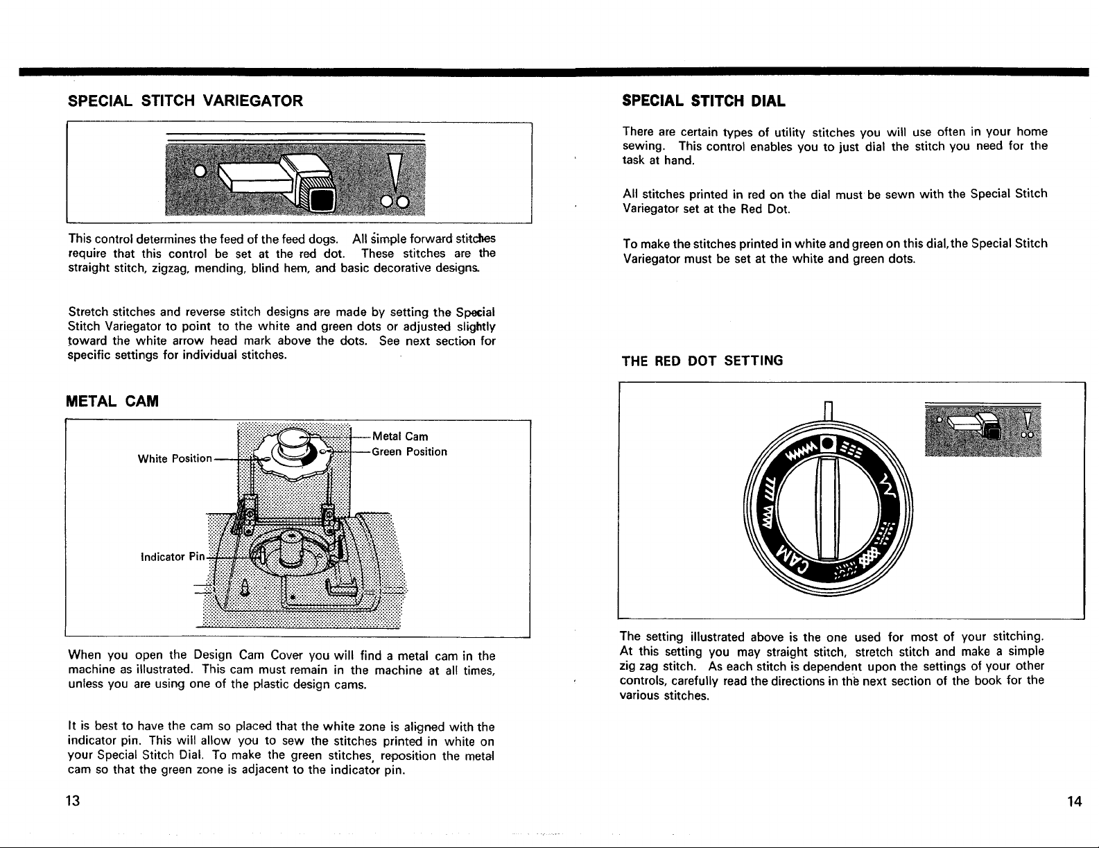
METAL CAM
Cam
White
Indicator Pin.
When you open the Design Cam Cover you will find a metal cam in the
machine as illustrated. This cam must remain in the machine at all times,
unless you are using one of the plastic design cams.
Position
To make the stitches printed in white and green on this dial,the Special Stitch
Variegator must be set at the white and green dots.
THE RED DOT SETTING
The setting illustrated above is the one used for most of your stitching.
At this setting you may straight stitch, stretch stitch and make a simple
zig zag stitch. As each stitch is dependent upon the settings of your other
controls, carefully read the directions in thi_ next section of the book for the
various stitches.
It is best to have the cam so placed that the white zone is aligned with the
indicator pin. This will allow you to sew the stitches printed in white on
your Special Stitch Dial. To make the green stitches, reposition the metal
cam so that the green zone is adjacent to the indicator pin.
13 14
 Loading...