

Use & Care Guide
Model No.
153.586320 30 Gallon Tall
153.586311 28 Gallon Short
153.586401 40 Gallon Tall
153.586501 50 Gallon Tall
153.586511 50 Gallon Medium
153.586411 40 Gallon Medium
Kenmore®
Electric
Water Heater
LOW LEAD
CONTENT
For potable water heating only.
Printed on 5/3/2019 1:29 PM CT
Not suitable for space heating.
INSTALLER: Affi x these instructions to or near
the water heater.
OWNER: Retain these instructions for future
reference.
ADVERTENCIA
Si no puede leer o entender el inglés y necesita el manual de
instrucciones en español, puede solicitarlo al 1-800-821-2017. NO
TRATE DE INSTALAR U OPERAR ESTE CALENTADOR DE AGUA
SI NO ENTIENDE LAS INSTRUCCIONES. No hacer caso de esta
advertencia podría originar lesiones graves o mortales.
P/N 100288150_2000545913_Rev. A (0617)
Sears Brands Management Corporation,
Hoffman Estates, IL 60179 U.S.A.
www.kenmore.com
1
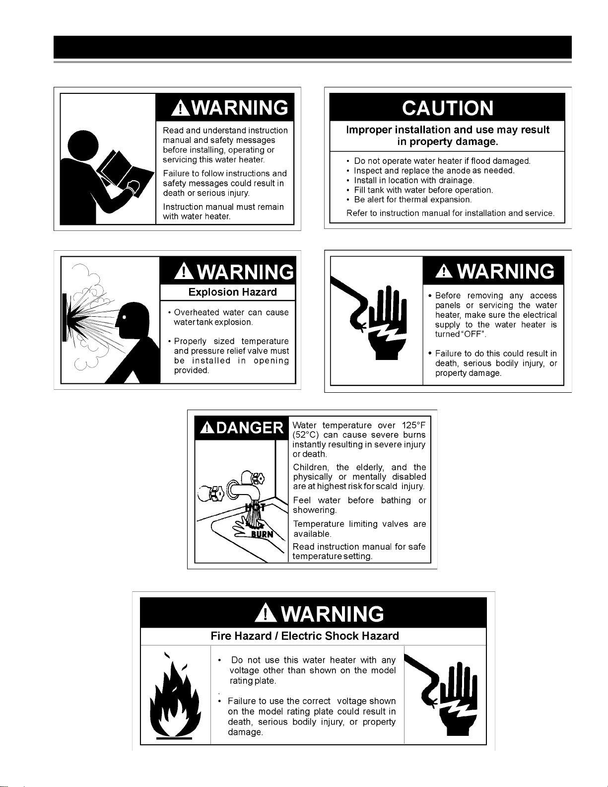
SAFE INSTALLATION, USE AND SERVICE
Your safety and the safety of others is extremely important in the installation, use and servicing of this water heater.
Many safety-related messages and instructions have been provided in this manual and on your own water heater to warn
you and others of a potential injury hazard. Read and obey all safety messages and instructions throughout this manual.
It is very important that the meaning of each safety message is understood by you and others who install, use or service
this water heater.
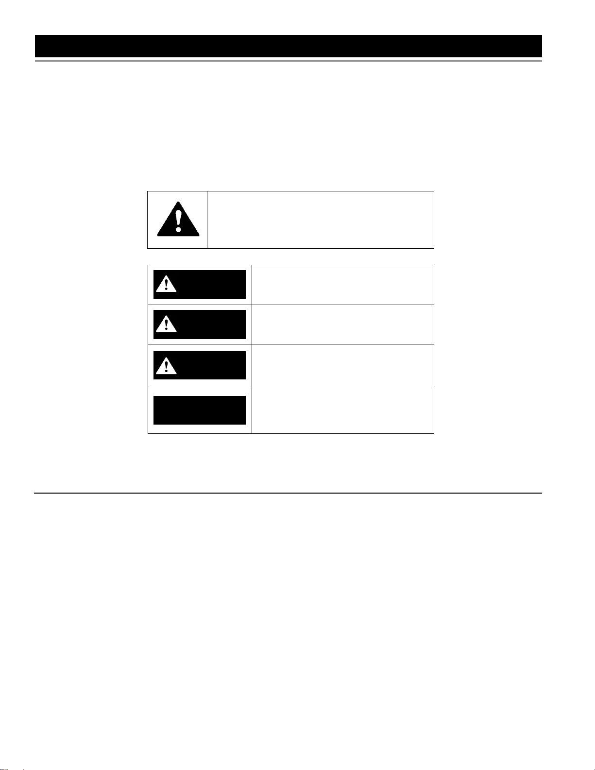
This is the safety alert symbol. It is used to alert you
to potential personal injury hazards. Obey all safety
messages that follow this symbol to avoid possible
injury or death.
DANGER indicates an imminently
DANGER
WARNING
hazardous situation which, if not avoided,
will result in death or injury.
WARNING indicates a potentially
hazardous situation which, if not avoided,
could result in death or injury.
CAUTION indicates a potentially
Printed on 5/3/2019 1:29 PM CT
CAUTION
CAUTION
hazardous situation which, if not avoided,
could result in minor or moderate injury.
CAUTION used without the safety alert
symbol indicates a potentially hazardous
situation which, if not avoided, could
result in property damage.
IMPORTANT DEFINITIONS
• Sears Service Center: The Sears Service Center has the ability equivalent to a licensed tradesman in the fi elds of plumbing and
electrical work including a thorough understanding of the requirements of the National Electrical Code as it relates to the installation
of electric water heaters. The Sears Service Center also has a thorough understanding of this instruction manual, and is able to
perform repairs strictly in accordance with the service guidelines provided by the manufacturer.
© Sears Brands Management Corporation
2
GENERAL SAFETY
Printed on 5/3/2019 1:29 PM CT
3

TABLE OF CONTENTS
SAFE INSTALLATION, USE AND SERVICE....................................................................................................................................... 2
GENERAL SAFETY............................................................................................................................................................................. 3
TABLE OF CONTENTS ....................................................................................................................................................................... 4
PRODUCT WARRANTY ..................................................................................................................................................................... 5
INTRODUCTION ................................................................................................................................................................................. 6
PRODUCT SPECIFICATIONS ............................................................................................................................................................ 6
MATERIALS AND BASIC TOOLS NEEDED ....................................................................................................................................... 7
Materials Needed .......................................................................................................................................................................... 7
Basic Tools .................................................................................................................................................................................... 7
Additional Tools Needed When Sweat Soldering ......................................................................................................................... 7
INSTALLATION INSTRUCTIONS .................................................................................................................................................. 8-16
Removing the Old Water Heater ................................................................................................................................................ 8,9
Facts to Consider About the Location ........................................................................................................................................... 9
Insulation Blankets ........................................................................................................................................................................ 9
Water Piping ...........................................................................................................................................................................10,11
Temperature-Pressure Relief Valve ........................................................................................................................................11,12
Filling the Water Heater .............................................................................................................................................................. 12
Converting the Lower Element .............................................................................................................................................. 12-15
Wiring ......................................................................................................................................................................................... 15
Wiring Diagrams ......................................................................................................................................................................... 16
SERVICE AND ADJUSTMENT .................................................................................................................................................... 17-23
Temperature Regulation ............................................................................................................................................................. 17
Thermostats ................................................................................................................................................................................ 17
Printed on 5/3/2019 1:29 PM CT
Temperature Settings .................................................................................................................................................................. 17
Upper and Lower Thermostat Adjustments ........................................................................................................................... 17,18
Anode Rod Inspection ................................................................................................................................................................ 18
Temperature-Pressure Relief Valve Operation ........................................................................................................................... 19
Draining and Flushing ................................................................................................................................................................. 19
Thermostat Removal/Replacement ............................................................................................................................................ 20
Element Cleaning/Replacement ............................................................................................................................................ 20-22
Drain Valve Washer Replacement .............................................................................................................................................. 22
Service ........................................................................................................................................................................................ 23
TROUBLESHOOTING GUIDE ..................................................................................................................................................... 24-27
Start Up Conditions ................................................................................................................................................................... 24
Thermal Expansion ............................................................................................................................................................. 24
Strange Sounds .................................................................................................................................................................. 24
Operational Conditions ............................................................................................................................................................... 24
Smelly Water ........................................................................................................................................................................ 24
“Air” in Hot Water Faucets .................................................................................................................................................. 25
Rumbling Noise ................................................................................................................................................................... 25
High Temperature Shut Off System ..................................................................................................................................... 25
Not Enough or No Hot Water ............................................................................................................................................... 25
Water Is Too Hot .................................................................................................................................................................. 25
Leakage Checkpoints ................................................................................................................................................................. 26
REPAIR PARTS LIST ................................................................................................................................................................... 27-28
NOTES ......................................................................................................................................................................................... 29-31
4

PRODUCT WARRANTY
KENMORE LIMITED WARRANTY
WITH PROOF OF SALE, the following warranty coverage applies
when this water heater is correctly connected, installed, operated and
maintained according to all supplied instructions. In all cases, replacement units, tanks or parts are warranted only for the unexpired portion
of the warranty period from the original date of sale.
FOR ONE YEAR from the date of sale this water heater is warranted
against defects in material or workmanship. A defective water heater
will receive free repair or replacement at option of seller.
FOR SIX YEARS from the date of sale this water heater is warranted
against leaks in the tank. If a tank leak occurs within the fi rst year, a
new water heater of equal capacity and quality will be supplied and
installed at no charge. If a tank leak occurs after the fi rst year, a new
water heater of equal capacity and quality will be supplied but not
installed at no charge. You are responsible for the labor cost of water
heater installation after the fi rst year from the date of sale.
FOR SIX YEARS from the date of sale all water heater parts are
warranted against defects in material or workmanship. If a part is
defective within the fi rst year, a new part will be supplied and installed
at no charge. If a part is defective after the fi rst year, a new part will
be supplied but not installed at no charge. You are responsible for the
labor cost of part installation after the fi rst year from the date of sale.
For warranty coverage details to obtain free repair or replacement,
visit the web page: www.kenmore.com/warranty
This warranty applies for only two years on the tank and one year on
all parts if this water heater is ever used in a residence of more than
one family or in a commercial, institutional or industrial installation.
This warranty covers ONLY defects in material and workmanship,
and will NOT pay for:
1. Expendable items that can wear out from normal use, including but
Printed on 5/3/2019 1:29 PM CT
not limited to fi lters, belts, bags or screw-in base light bulbs.
2. A service technician to clean or maintain this appliance, or to
instruct the user in correct appliance installation, operation and
maintenance.
3. Service calls to correct appliance installation not performed by
Sears authorized service agents, or to repair problems with house
fuses, circuit breakers, house wiring, and plumbing or gas supply
systems resulting from such installation.
4. Damage to or failure of this appliance resulting from installation not
performed by Sears authorized service agents, including installation that was not in accord with electrical, gas or plumbing codes.
5. Damage to or failure of this appliance, including discoloration or
surface rust, if it is not correctly operated and maintained according to all supplied instructions.
6. Damage to or failure of this appliance, including discoloration or
surface rust, resulting from accident, alteration, abuse, misuse or
use for other than its intended purpose.
7. Damage to or failure of this appliance, including discoloration or
surface rust, caused by the use of detergents, cleaners, chemicals
or utensils other than those recommended in all instructions supplied with the product.
8. Damage to or failure of parts or systems resulting from unauthorized modifi cations made to this appliance.
9. Service to an appliance if the model and serial plate is missing,
altered, or cannot easily be determined to have the appropriate
certifi cation logo.
Disclaimer of implied warranties; limitation of remedies
Customer’s sole and exclusive remedy under this limited warranty
shall be product repair or replacement as provided herein. Implied
warranties, including warranties of merchantability or fi tness for a
particular purpose, are limited to one year on the water heater, and
six years on the tank and parts, or the shortest period allowed by law.
Seller shall not be liable for incidental or consequential damages.
Some states do not allow the exclusion or limitation of incidental or
consequential damages, or limitation on the duration of implied warranties of merchantability or fi tness, so these exclusions or limitations
may not apply to you.
This warranty applies only while this appliance is used in the United
States.
This warranty gives you specifi c legal rights, and you may also have
other rights which vary from state to state.
Sears Brands Management Corporation,
Hoffman Estates, IL 60179
Master Protection Agreements
Congratulations on making a smart purchase. Your new Kenmore
Elite® product is designed and manufactured for years of dependable
operation. But like all products, it may require preventive maintenance
or repair from time to time. That’s when having a Master Protection
Agreement can save you money and aggravation.
The Master Protection Agreement also helps extend the life of your
new product. Here’s what the Agreement* includes:
The Master Protection Agreement also helps extend the life of your
new product. Here’s what the Agreement* includes:
• Parts and labor not just for repairing defects, but to help keep
products operating properly under normal use. Our coverage goes
well beyond the product warranty. No deductibles, no functional failure
excluded from coverage— real protection.
• Expert service by experienced service technicians trusted in millions
of homes every year.
• Unlimited service calls and nationwide service, as often as you want
us, whenever you want us.
• “No-lemon” guarantee – replacement of your covered product after
three separate product failures occur within twelve months and a fourth
repair is required. Includes free delivery and installation, if necessary,
of replacement product.
• Product replacement if your covered product can’t be fi xed.
• Annual Preventive Maintenance Check at your request – no extra
charge.
• Fast help by phone – phone support from a service agent on all products
to help trouble-shoot problems. Think of us as a “talking owner’s manual.”
• Power surge protection against electrical damage due to power
fl uctuations.
• $300 Food Loss Protection for any food spoilage that is the result of
mechanical failure of any covered refrigerator or freezer.
• Service Promise: $50 if fi rst attempt repair of your covered kitchen or
laundry product can’t be accomplished and product is not usable while
awaiting further repair service.
• 25% discount off the regular price of any non-covered repair service
and related installed parts.
Once you purchase the Agreement, a simple phone call is all that it
takes for you to schedule service. You can call anytime day or night.
The Master Protection Agreement is a risk free purchase. If you cancel
for any reason during the product warranty period, we will provide a
full refund. Or, a prorated refund anytime after the product warranty
period expires. Purchase your Master Protection Agreement today!
Some limitations and exclusions apply. For prices and additional
information in the U.S.A. call 1-800-827-6655.
* Coverage in Canada varies on some items. For full details call
Sears Canada at 1-800-361-6665.
Sears Installation Service
For Sears professional installation of home appliances, garage door
openers, water heaters, and other major home items, in the U.S.A.
call 1-844-553-6667, and in Canada call 1-800-469-4663.
5
INTRODUCTION
Thank You for purchasing a Kenmore water heater. Properly
installed and maintained, it should give you years of trouble free
service. It is strongly suggested that this new water heater be
professionally installed, contact the local Sears Service Center or
any Sears store. They will arrange for prompt, quality installation
by Sears authorized contractors.
Abbreviations Found In This Instruction Manual:
UL – Underwriters Laboratories Inc.
NEC – National Electrical Code
ANSI – American National Standards Institute
AHRI - Air Conditioning, Heating and Refrigeration Institute
• Read the General Safety section, page 3 of this manual fi rst
and then the entire manual carefully. If you don’t follow the
safety rules, the water heater will not operate properly. It
could cause DEATH, SERIOUS BODILY INJURY AND/OR
PROPERTY DAMAGE.
This manual contains instructions for the installation,
operation, and maintenance of this electric water heater. It
also contains warnings throughout the manual that you must
read and be aware of. All warnings and all instructions are
essential to the proper operation of the water heater and your
safety. Since we cannot put everything on the fi rst few pages,
READ THIS ENTIRE MANUAL BEFORE ATTEMPTING TO
INSTALL OR OPERATE THE WATER HEATER.
Printed on 5/3/2019 1:29 PM CT
• The product is certifi eld to comply with a maximum weighted
average of 0.25% lead content as required in some areas.
• The installation must conform with the instructions in this
manual; electric company rules; and Local Codes, or in
the absence of Local Codes, with the current edition of the
NEC - National Electrical Code, NFPA 70. This publication
is available from your local government or public library or
electric company or by writing Underwriters Laboratories Inc.,
333 Pfi ngsten Road, Northbrook, IL 60062.
• If after reading this manual you have any questions or do not
understand any portion of the instructions, call Sears Service
Center.
• Carefully plan the place where you are going to put the water
heater. Correct electrical wiring and connections are very
important in preventing death from possible electrical shock
and fi res.
• Keep combustibles such as boxes, magazines, clothes, etc.,
away from water heater area.
Examine the location to ensure the water heater complies with
the Facts to Consider About the Location section.
For California installation, this water heater must be braced,
anchored, or strapped to avoid falling or moving during an
earthquake. See instructions for correct installation procedures.
Instructions may be obtained from California’s Office of
the State Architect, 1102 Q Street, Suite 5100, Sacramento,
CA 95811. Instructions can also be downloaded to your computer
at www.dsa.dgs.ca.gov/Pubs.
Massachusetts Code requires this water heater to be installed
in accordance with Massachusetts 248-CMR 2.00; State
Plumbing Code and 248-CMR 5.00. In the Commonwealth of
Massachusetts, this product must be installed by a licensed
plumber or gasfi tter.
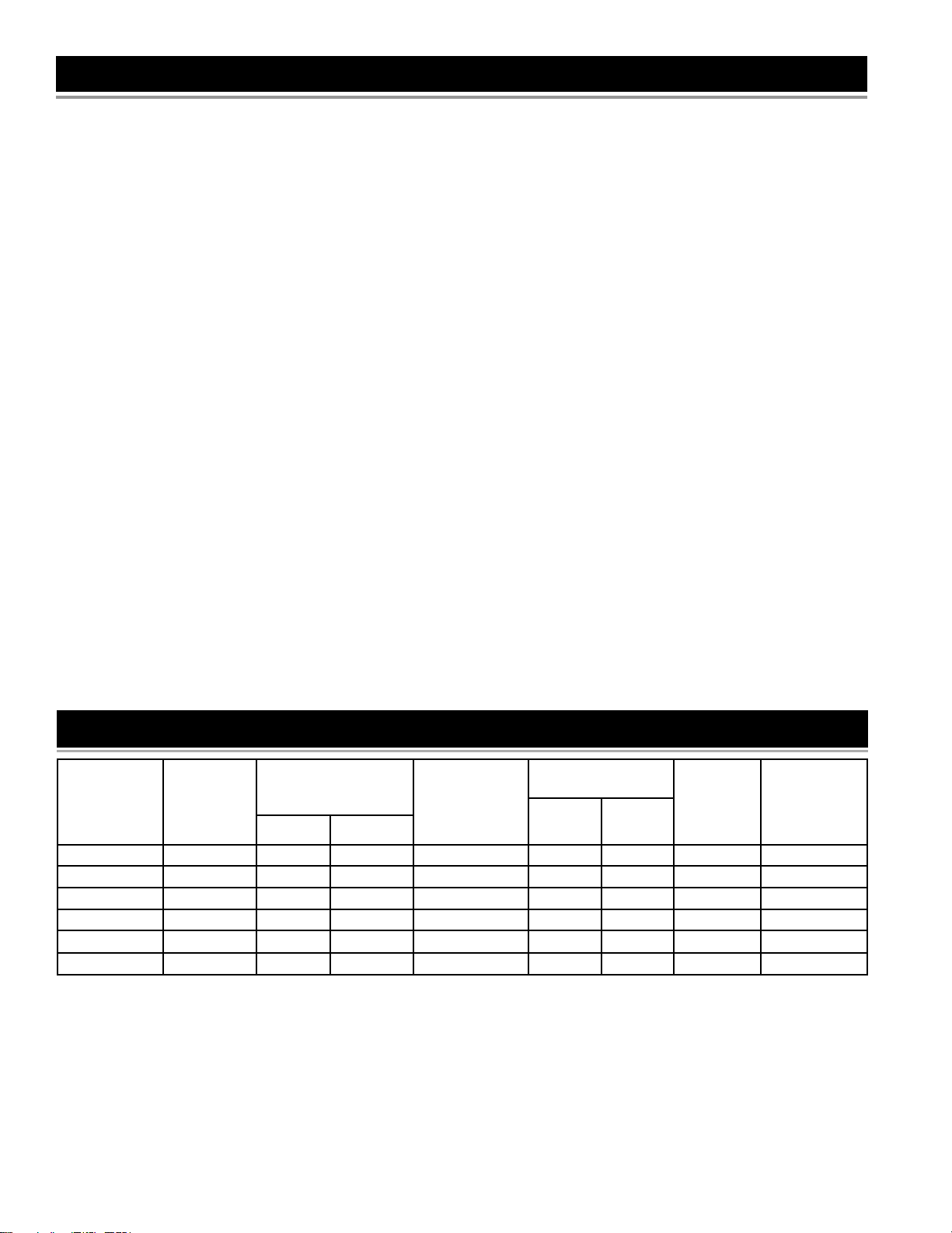
PRODUCT SPECIFICATIONS
NOMINAL
TANK
MODEL
NUMBER
153.586320 30 (114) 19.0 (483) 46.75 (1187) 21 4500 4500 10 30
153.586311 28 (106) 22.0 (559) 31.25 (794) 21 4500 4500 10 30
153.586401 40 (151) 18.0 (458) 61.25 (1557) 21 4500 4500 10 30
153.586501 50 (189) 20.5 (521) 60.5 (1537) 21 4500 4500 10 30
153.586511 50 (189) 23.0 (584) 49.0 (1245)
153.586411 40 (151) 20.5 (521) 49.75 (1264)
* Wiring size based on standard 60°C copper wire. If distance from fuse box to water heater is more than 90 feet, refer to your local
electrical code.
CAPACITY
IN GALLONS
(LITERS)
DIMENSIONS IN
INCHES (mm)
RECOVERY RATE
GALS. PER HOUR
@90°F RISE
21 4500 4500
21 4500 4500
ELEMENT WATTAGE
@ 240 VOLTS
MINIMUM
WIRE SIZE*
(GAUGE)
10 30
10 30
MAXIMUM
FUSE
OR CIRCUIT
BREAKER
SIZE (AMPS)LOWER UPPERDIA. HEIGHT
6
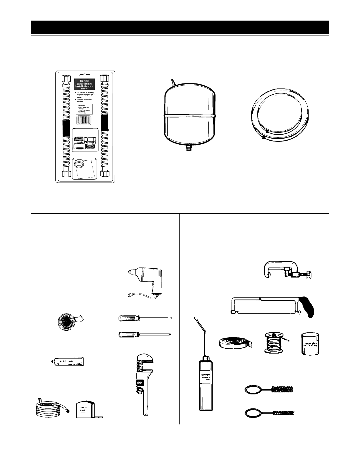
MATERIALS AND BASIC TOOLS NEEDED
Materials Needed
To simplify the installation Sears has available the installation parts shown below. You may or may not need all of these materials,
depending on your type of installation.
WATER HEATER INSTALLATION KIT
WITH FLEXIBLE CONNECTORS FOR 3/4”
THREADED OR COPPER PLUMBING.
Printed on 5/3/2019 1:29 PM CT
Basic Tools
You may or may not need all of these tools, depending on your
type of installation. These tools can be purchased at your local
Sears store.
Pipe Wrench (2)
Screwdriver
6 Foot Tape or Folding Rule
Garden Hose
Drill
Pipe Dope or Tefl on Tape
ROLL OF TEFLON TAPE (USE ON
WATER CONNECTIONS)
EXPANSION TANKS FOR THERMAL
EXPANSION CONDITIONS AVAILABLE IN
2 GALLONS , AND 5 GALLONS CAPACITY
THROUGH LOCAL SEARS STORE OR
SERVICE CENTER.
DRILL
SLOT-HEAD SCREWDRIVER
PHILLIPS SCREWDRIVER
METAL DRAIN PANS AVAILABLE
IN 20” DIAMETER FOR WATER
HEATERS HAVING A DIAMETER 18”
OR LESS AND IN 24” DIAMETER
FOR WATER HEATERS HAVING A
DIAMETER OF 22” OR LESS.
Additional Tools Needed When Sweat
Soldering
Tubing Cutters or Hacksaw
Propane Torch
Soft Solder
Solder Flux
Emery Cloth
Wire Brushes
TUBING CUTTER
HACKSAW
PIPE DOPE (SQUEEZE TUBE)
USE FOR WATER CONNECTIONS
ROLL OF
EMERY CLOTH
3/4” (19 mm) WIRE BRUSH
PIPE WRENCHGARDEN HOSE 6 FOOT TAPE
7
PROPANE
TORCH
1/2” (13 mm) WIRE BRUSH
ROLL OF
LEAD-FREE
SOFT SOLDER
SOLDER
FLUX
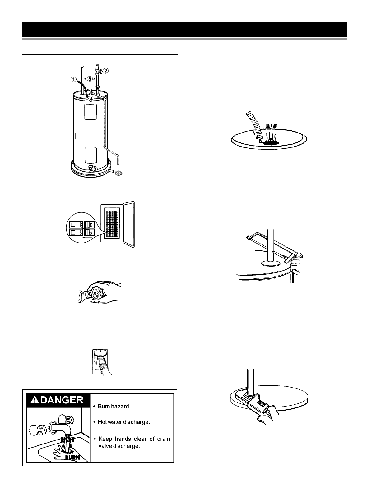
INSTALLATION INSTRUCTIONS
Removing the Old Water Heater
FIGURE 1.
1. Turn “OFF” electrical supply to the water heater.
The water passing out of the drain valve may be extremely hot.
To avoid being scalded, make sure all connections are tight and
that the water fl ow is directed away from any person.
4. Check again to make sure the electrical supply is turned
“OFF” to the water heater. Then unplug the water heater
(cord set) or disconnect the electrical supply connection from
the water heater junction box.
FIGURE 5.
5. If you have copper piping to the water heater, the two
copper water pipes can be cut with a hacksaw approximately
four inches away from where they connect to the water
heater. This will avoid cutting off the pipes too short.
Additional cuts can be made later if necessary. Disconnect
the temperature-pressure relief valve drain line. When
the water heater is drained, disconnect the hose from the
drain valve. Close the drain valve. The water heater is now
completely disconnected and ready to be removed.
Printed on 5/3/2019 1:29 PM CT
FIGURE 2.
2. Open a nearby hot water faucet until the water is no longer
hot. When the water has cooled, turn “OFF” the water supply
to the water heater at the water shut-off valve or water meter.
FIGURE 3.
3. Attach a hose to the water heater drain valve and put the other
end in a fl oor drain or outdoors. Open the water drain valve.
Open a nearby hot water faucet which will relieve pressure
in the water heater and speed draining.
FIGURE 4.
FIGURE 6.
6. If you have galvanized pipe to the water heater, loosen the
two galvanized pipes with a pipe wrench at the union in each
line. Also disconnect the piping remaining to the water heater.
These pieces should be saved since they may be needed
when reconnecting the new water heater. Disconnect the
temperature-pressure relief valve drain line. When the water
heater is drained, disconnect the hose from the drain valve.
Close the drain valve. The water heater is now completely
disconnected and ready to be removed.
FIGURE 7.
8
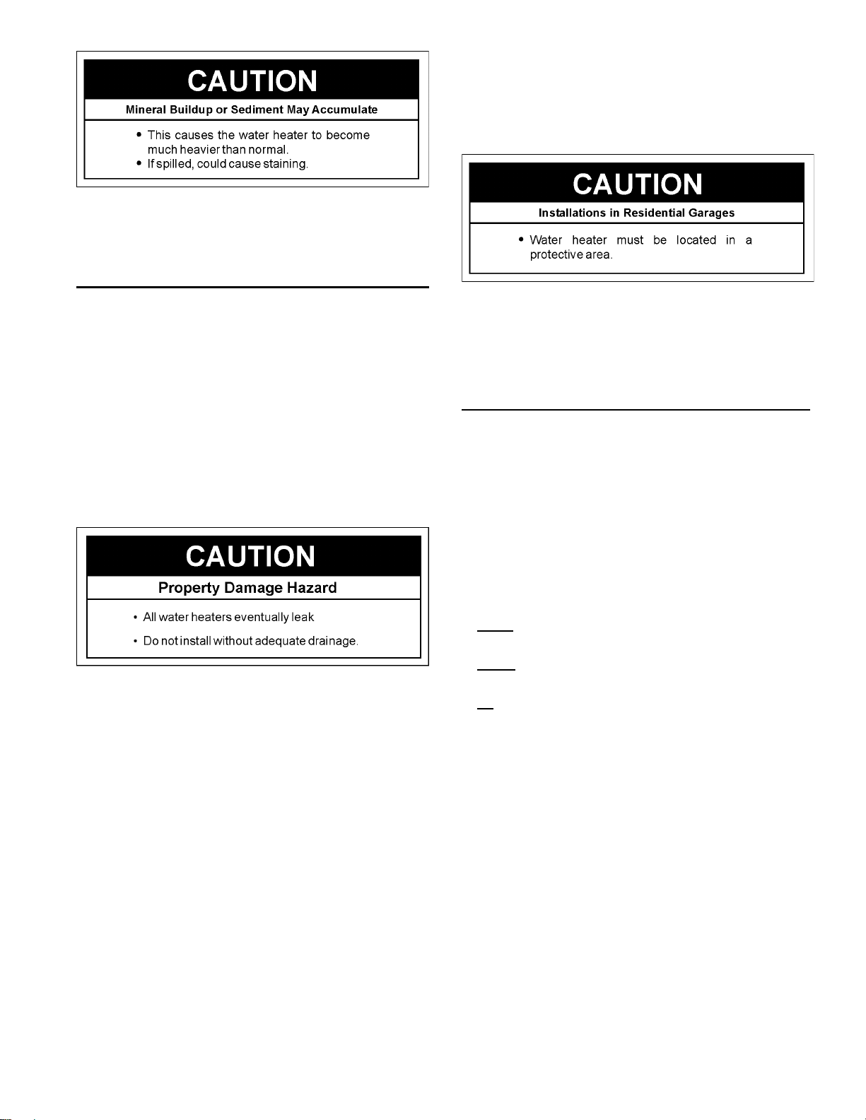
Mineral buildup or sediment may have accumulated in the old
water heater. This causes the water heater to be much heavier
than normal and this residue, if spilled out, could cause staining.
Facts to Consider About the Location
You should carefully choose an indoor location for the new water
heater, because the placement is a very important consideration
for the safety of the occupants in the building and for the most
economical use of the appliance. This water heater is not
intended for outdoor installation.
Whether replacing an old water heater or putting the water heater
in a new location, the following critical points must be observed.
• The location selected should be indoors as close to and as
centralized with the water piping system as possible. This
water heater, as well as all water heaters, will eventually leak.
Do not install without adequate drainage provisions so water
fl ow will not cause damage.
Printed on 5/3/2019 1:29 PM CT
• Sensors mounted in the metal drain pan that turn off the
water supply to the entire home when water is detected in the
drain pan.
• Water supply shut-off devices that activate based on the water
pressure differential between the cold water and hot water pipes
connected to the water heater.
INSTALLATION IN RESIDENTIAL GARAGES: The water heater
must be located and/or protected so it is not subject to physical
damage by a moving vehicle.
• The location selection must provide adequate clearances for
servicing and proper operation of the water heater.
Insulation Blankets
Insulation blankets are available to the general public for external
use on electric water heaters but are not necessary with this
product. The purpose of an insulation blanket is to reduce
the standby heat loss encountered with storage tank heaters.
Your water heater meets or exceeds the National Appliance
Energy Conversation Act standards with respect to insulation
and standby loss requirements, making an insulation blanket
unnecessary.
Should you choose to apply an insulation blanket to this heater,
you should follow these instructions below. Failure to follow these
instructions can result in fi re, serious personal injury, or death.
WATER HEATERS EVENTUALLY LEAK: Installation of the water
heater must be accomplished in such a manner that if the tank
or any connections should leak, the fl ow of water will not cause
damage to the structure. When such locations cannot be avoided,
a suitable metal drain pan should be installed under the water
heater. Drain pans are available at your local Sears stores. Such
drain pans must be piped to an adequate drain.
Water heater life depends upon water quality, water pressure
and the environment in which the water heater is installed. Water
heaters are sometimes installed in locations where leakage may
result in property damage, even with the use of a metal drain pan
piped to a drain. However, unanticipated damage can be reduced
or prevented by a leak detector or water shut-off device used
in conjunction with a piped metal drain pan. These devices are
available from some plumbing supply wholesalers and retailers,
and detect and react to leakage in various ways:
• Sensors mounted in the metal drain pan that trigger an alarm or turn
off the incoming water to the water heater when leakage is detected.
• Do not cover the temperature and pressure relief (T & P) valve
with an insulation blanket.
• Do not cover the instruction manual. Keep it on the side of
the water heater or nearby for future reference.
• Do obtain new warning and instruction labels for placement
on the blanket directly over the existing labels.
9
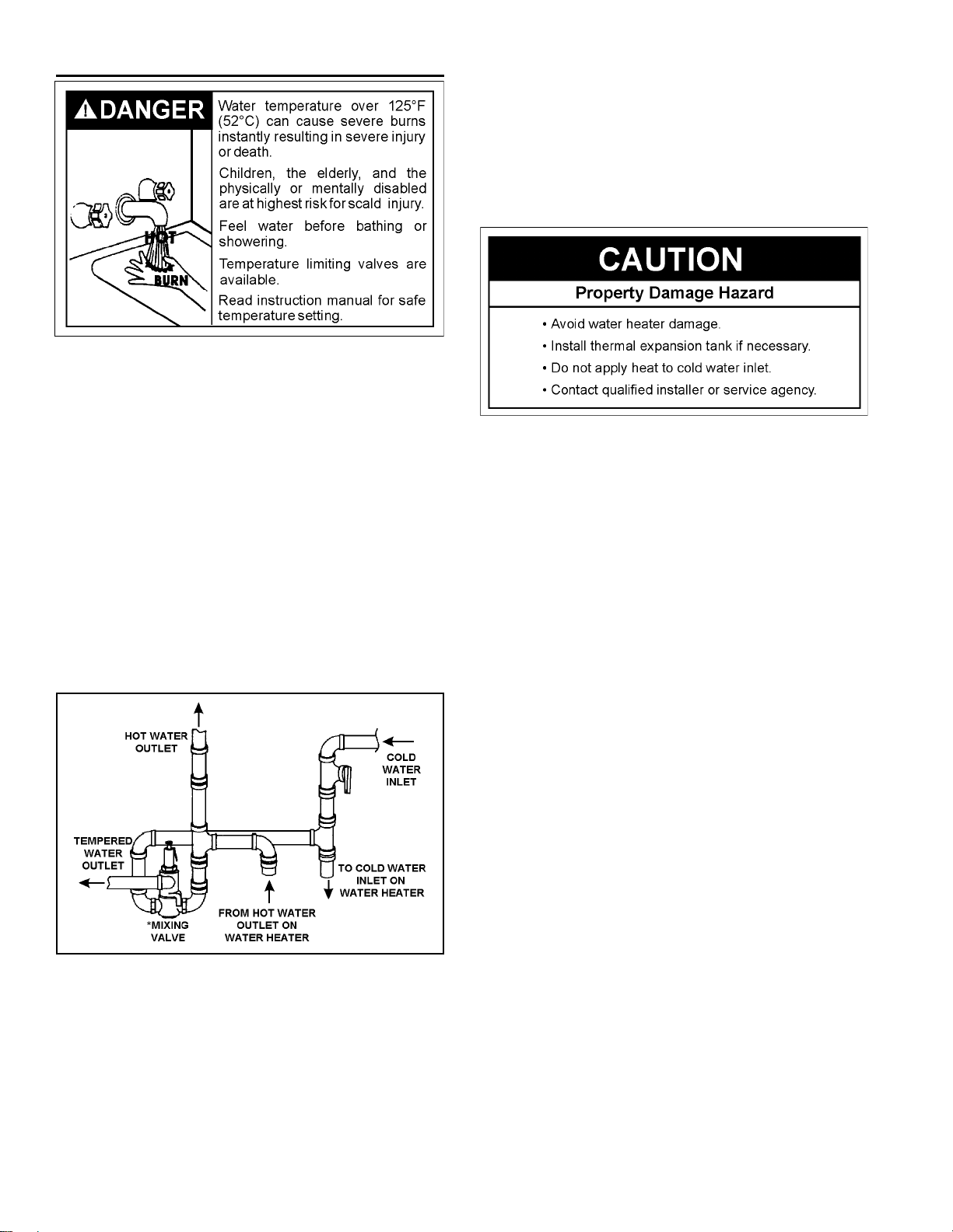
Water Piping
HOTTER WATER CAN SCALD: Water heaters are intended
to produce hot water. Water heated to a temperature which
will satisfy clothes washing, dish washing, and other sanitizing
needs can scald and permanently injure you upon contact. Some
people are more likely to be permanently injured by hot water
than others. These include the elderly, children, the infi rm, or
physically/mentally handicapped. If anyone using hot water in
your home fi ts into one of these groups or if there is a local code
or state law requiring a certain temperature water at the hot water
tap, then you must take special precautions. In addition to using
the lowest possible temperature setting that satisfi es your hot
water needs, a means such as a mixing valve should be used at
the hot water taps used by these people or at the water heater.
Mixing valves are available at plumbing supply or hardware
Printed on 5/3/2019 1:29 PM CT
stores. Follow manufacturers instructions for installation of the
valves. Before changing the factory setting on the thermostat,
read the Temperature Regulation section in this manual.
See Figure 8 (below) for mixing valve usage.
meter with a check valve, etc... in the cold water supply; means
must be provided to control thermal expansion. Contact the local
utility or Sears Service Center on how to control this situation
NOTE: If using copper tubing, solder tubing to an adapter
before attaching the adapter to the water inlet connection.
Do not solder the water supply lines directly to the cold
water inlet. It will harm the dip tube and damage the tank.
NOTE: To protect against untimely corrosion of hot and cold
water fi ttings, it is strongly recommended that di-electric
unions or couplings be installed on this water heater when
connected to copper pipe.
1. Look at the top cover of the water heater. The hot water outlet
is marked hot. Put two or three turns of tefl on tape around
the threaded end of the threaded-to-sweat coupling and
around both ends of the 3/4” threaded nipple. Using fl exible
connectors, connect the hot water pipe to the hot water outlet
of the water heater.
2. Look at the top cover of the water heater. The cold water inlet
is marked cold. Put two or three turns of tefl on tape around
the threaded end of the threaded-to-sweat coupling and
around both ends of the 3/4” threaded nipple. Using fl exible
connectors, connect the cold water pipe to the cold water inlet
of the water heater.
.
FIGURE 8.
The water supply pressure should not exceed 80 psi. If this
occurs, a pressure reducing valve with a bypass should be
installed in the cold water inlet line. This should be placed on
the supply to the entire house in order to maintain equal hot and
cold water pressures.
Figure 8 shows the attachment of the water piping to the water
heater. The water heater is equipped with 3/4” water connections.
If a water heater is installed in a closed water supply system;
such as one having a back-fl ow preventer, check valve, water
NOTE: Your water heater is insulated to minimize heat
loss from the tank. Further reduction in heat loss can be
accomplished by insulating the hot water lines from the
water heater.
10

FIGURE 9.
Explosion Harzard
7HPSHUDWXUHSUHVVXUHUHOLHI
YDOYHPXVWFRPSO\ZLWK$16,
=&6$DQG$60(
FRGH
3URSHUO\VL]HGWHPSHUDWXUH-
SUHVVXUHUHOLHIYDOYHPXVWEH
LQVWDOOHGLQRSHQLQJSURYLGHG
'RQRWSOXJEORFNRUFDSWKH
GLVFKDUJHOLQH
)DLOXUHWRIROORZWKLVZDUQLQJ
FDQUHVXOWLQH[FHVVLYHWDQN
SUHVVXUHVHULRXVLQMXU\RU
GHDWK
Printed on 5/3/2019 1:29 PM CT
Temperature-Pressure Relief Valve
This heater is provided with a properly certifi ed combination
temperature - pressure relief valve by the manufacturer.
The valve is certifi ed by a nationally recognized testing laboratory
that maintains periodic inspection of production of listed
equipment of materials as meeting the requirements for Relief
Valves for Hot Water Supply Systems, ANSI Z21.22 • CSA 4.4,
and the code requirements of ASME.
If replaced, the valve must meet the requirements of local codes,
but not less than a combination temperature and pressure relief
valve certifi ed as indicated in the above paragraph.
The valve must be marked with a maximum set pressure not to
exceed the marked hydrostatic working pressure of the water
heater (150 psi = 1,035 kPa) and a discharge capacity not less
than the water heater input rate as shown on the model rating
plate. (For electric heaters, watts x 3.412 equals Btu/hr input rate)
For safe operation of the water heater, the relief valve must not
be removed from its designated opening nor plugged.
The temperature-pressure relief valve must be installed directly
into the fi tting of the water heater designed for the relief valve.
Position the valve downward and provide tubing so that any
discharge will exit only within 6 inches (15.2 cm) above, or at any
distance below the structural fl oor. Be certain that no contact is
made with any live electrical part. The discharge opening must
not be blocked or reduced in size under any circumstances.
Excessive length, over 30 feet (9.14 m), or use of more than
four elbows can cause restriction and reduce the discharge
capacity of the valve.
No valve or other obstruction is to be placed between the relief
valve and the tank. Do not connect tubing directly to discharge
11

drain unless a 6 inch (153 mm) air gap is provided. To prevent
bodily injury, hazard to life, or property damage, the relief
valve must be allowed to discharge water in quantities should
circumstances demand. If the discharge pipe is not connected
to a drain or other suitable means, the water fl ow may cause
property damage.
The Discharge Pipe:
• Shall not be smaller in size than the outlet pipe size of the
valve, or have any reducing couplings or other restrictions.
• Shall not be plugged or blocked.
• Shall be of material listed for hot water distribution.
• Shall be installed so as to allow complete drainage of both the
temperature-pressure relief valve, and the discharge pipe.
• Shall terminate a maximum of six inches (15.2 cm) above a
fl oor drain or external to the building. In cold climates, it is
recommended that the discharge pipe be terminated at an
adequate drain inside the building.
• Shall not have any valve between the relief valve and tank.
FIGURE 10.
Filling the Water Heater
Printed on 5/3/2019 1:29 PM CT
The temperature-pressure relief valve must be manually
operated at least once a year. Caution should be taken to
ensure that (1) no one is in front of or around the outlet of the
temperature-pressure relief valve discharge line, and (2) the
water manually discharged will not cause any bodily injury or
property damage because the water may be extremely hot.
If after manually operating the valve, it fails to completely reset
and continues to release water, immediately close the cold water
inlet to the water heater, follow the draining instructions, and
replace the temperature-pressure relief valve with a new one.
Never use this water heater unless it is completely full of water.
To prevent damage to the tank and heating element, the tank
must be fi lled with water. Water must fl ow from the hot water
faucet before turning “ON” power.
To fi ll the water heater with water:
1. Close the water heater drain valve by turning the handle to
the right (clockwise). The drain valve is located on the lower
front of the water heater.
2. Open the cold water supply valve to the water heater.
NOTE: The cold water supply valve must be left open when
the water heater is in use.
3. To ensure complete fi lling of the tank, allow air to exit by
opening the nearest hot water faucet. Allow water to run until
a constant fl ow is obtained. This will let air out of the water
heater and the piping.
4. Check all new water piping for leaks. Repair as needed.
12

Wiring
You must provide all wiring of the proper size outside of the
water heater. You must obey local codes and electric company
requirements when you install this wiring.
If you are not familiar with electric codes and practices, or if you
have any doubt, even the slightest doubt, in your ability to connect
the wiring to this water heater, obtain the service of a competent
electrician. Contact your Sears salesperson to arrange for a
professional electrician.
WATER HEATERS EQUIPPED FOR ONE VOLTAGE ONLY:
This water heater is equipped for one type voltage only. Check
the rating plate near the bottom access panel for the correct
voltage. DO NOT use this water heater with any voltage other
than the one shown on the model rating plate. Failure to use the
correct voltage can cause problems which can result in DEATH,
SERIOUS BODILY INJURY, OR PROPERTY DAMAGE. If you
have any questions or doubts consult your electric company.
• The length in any ground return path does not
exceed 6 feet (1.82 m).
• The circuit conductors contained therein are protected
by overcurrent devices rated at 20 amperes or less.
• The conduit or tubing is terminated in fi ttings approved
for grounding.
For complete grounding details and all allowable exceptions,
refer to the current edition of the NEC - National Electrical Code
NFPA 70.
4. A standard 1/2” conduit opening has been made in the water
heater junction box for the conduit connection.
5. A wiring diagram (Figure 24) has been provided to show the
connections between the water heater and the power supply.
• Two Wire Connection Diagrams: is the most common
requiring you to simply connect red to red, black to
black, and the ground wire to the green ground screw
in the junction box of the water heater.
6. Use wire nuts and connect the power supply wiring to the
wires inside the water heater’s junction box.
7. The water heater must be electrically “grounded” by the
installer. A green ground screw has been provided on the
water heater’s junction box. Connect ground wire to this
location.
8. Replace the wiring junction cover using the screw provided
JUNCTION BOX COVER
Printed on 5/3/2019 1:29 PM CT
If wiring from your fuse box or circuit breaker box was aluminum
for your old water heater, replace it with copper wire. If you wish
to reuse the existing aluminum wire, have the connection at the
water heater made by a competent electrician. Contact your
Sears salesperson to arrange for a professional electrician.
1. Provide a way to easily shut off the electric power when
working on the water heater. This could be with a circuit
breaker or fuse block in the entrance box or a separate
disconnect switch.
2. Install and connect a circuit directly from the main fuse or
circuit breaker box. This circuit must be the right size and
have its own fuse or circuit breaker. Refer to the chart in the
Product Specifi cations section for the correct size wire and
fuse or circuit breaker.
3. If metal conduit is used for the grounding conductor:
a. The grounding electrode conductor shall be of copper,
aluminum, or copperclad aluminum. The material
shall be of one continuous length without a splice or
joint.
b. Rigid metal conduit, intermediate metal conduit, or
electrical metallic tubing may be used for the grounding
means if conduit or tubing is terminated in fi ttings
approved for grounding.
c. Flexible metal conduit or flexible metallic tubing
shall be permitted for grounding if all the following
conditions are met:
BLACK WIRES
GROUND WIRES
(GROUND SCREW IS
UNDER THE COVER)
RED WIRES
1/2” CONDUIT
CONNECTION
FIGURE 11.
FROM HOME
ELECTRICAL SERVICE
13

Wiring Diagram
STANDARD WIRING FOR 2 WIRE LEAD WATER HEATERS
NON-SIMULTANEOUS OPERATION 240 VOLT DOUBLE
ELEMENT
A-6
Printed on 5/3/2019 1:29 PM CT
FIGURE 12.
14

SERVICE AND ADJUSTMENT
Temperature Regulation
HOTTER WATER CAN SCALD: Water heaters are intended
to produce hot water. Water heated to a temperature which
will satisfy clothes washing, dish washing, and other sanitizing
needs can scald and permanently injure you upon contact. Some
people are more likely to be permanently injured by hot water
than others. These include the elderly, children, the infi rm, or
physically/mentally handicapped. If anyone using hot water in
your home fi ts into one of these groups or if there is a local code
or state law requiring a certain temperature water at the hot water
tap, then you must take special precautions. In addition to using
the lowest possible temperature setting that satisfi es your hot
Printed on 5/3/2019 1:29 PM CT
water needs, some type of tempering device, such as a mixing
valve, should be used at the hot water taps used by these people
or at the water heater. Mixing valves are available at plumbing
supply or hardware stores. Follow manufacturers instructions for
installation of the valves, Before changing the factory setting of
the thermostat see Temperature Settings table at right.
Never allow small children to use a hot water tap, or to draw
their own bath water. Never leave a child or handicapped person
unattended in a bathtub or shower.
Thermostats
The lower thermostat is factory set at a position which
approximates 120°F (49°C), and is adjustable if a different water
temperature is desired. Read all warnings in this manual and on
the water heating before proceeding.
FIGURE 14.
Temperature Settings
NOTE: Water temperature range of 120°—140°F (49°-60°C)
recommended by most dishwasher manufacturers.
TABLE 1: WATER TEMPERATURES
Water
Temperature
°F
110 (normal shower temp.)
116 (pain threshold)
116 35 minutes 45 minutes
122 1 minute 5 minutes
131 5 seconds 25 seconds
140 2 seconds 5 seconds
149 1 second 2 seconds
154 instantaneous 1 second
(U.S. Government Memorandum, C.P.S.C., Peter L. Armstrong, Sept. 15,1978)
Time for 1st
Degree Burn
(Less Severe Burns)
Time for Permanent Burns
2nd & 3rd Degree
(Most Severe Burns)
The thermostats of this water heater have been factory set at
a position which approximates 120°F (49°C), to reduce the risk
of scald injury.
The upper thermostat is factory set at a position which
approximates 120°F (49°C), and is adjustable if a different water
temperature is desired. Read all warnings in this manual and on
the water heating before proceeding.
FIGURE 13.
Upper and Lower Thermostat Adjustments
(Refer to thermostat illustrations under Thermostats section)
NOTE: It is not necessary to adjust the upper thermostat.
However, if it is adjusted above the factory set point of 120°F
(49°C), it is recommended that it not be set higher than the lower
thermostat setting.
15
The upper and lower thermostats are adjustable if a different
water temperature is desired. Read all warnings in the
Temperature-Regulation section before proceeding.
1. Turn “OFF” the electric power to the water heater at the
junction box.
2. Take off the upper and/or lower access panel(s), then fold the
insulation back to expose the thermostat.
3. The slotted adjustment can be turned clockwise (
a screwdriver to increase the temperature setting or counter
clockwise (
4. Replace the insulation and access panel.
5. Turn “ON” the power supply.
) to decrease the temperature setting.
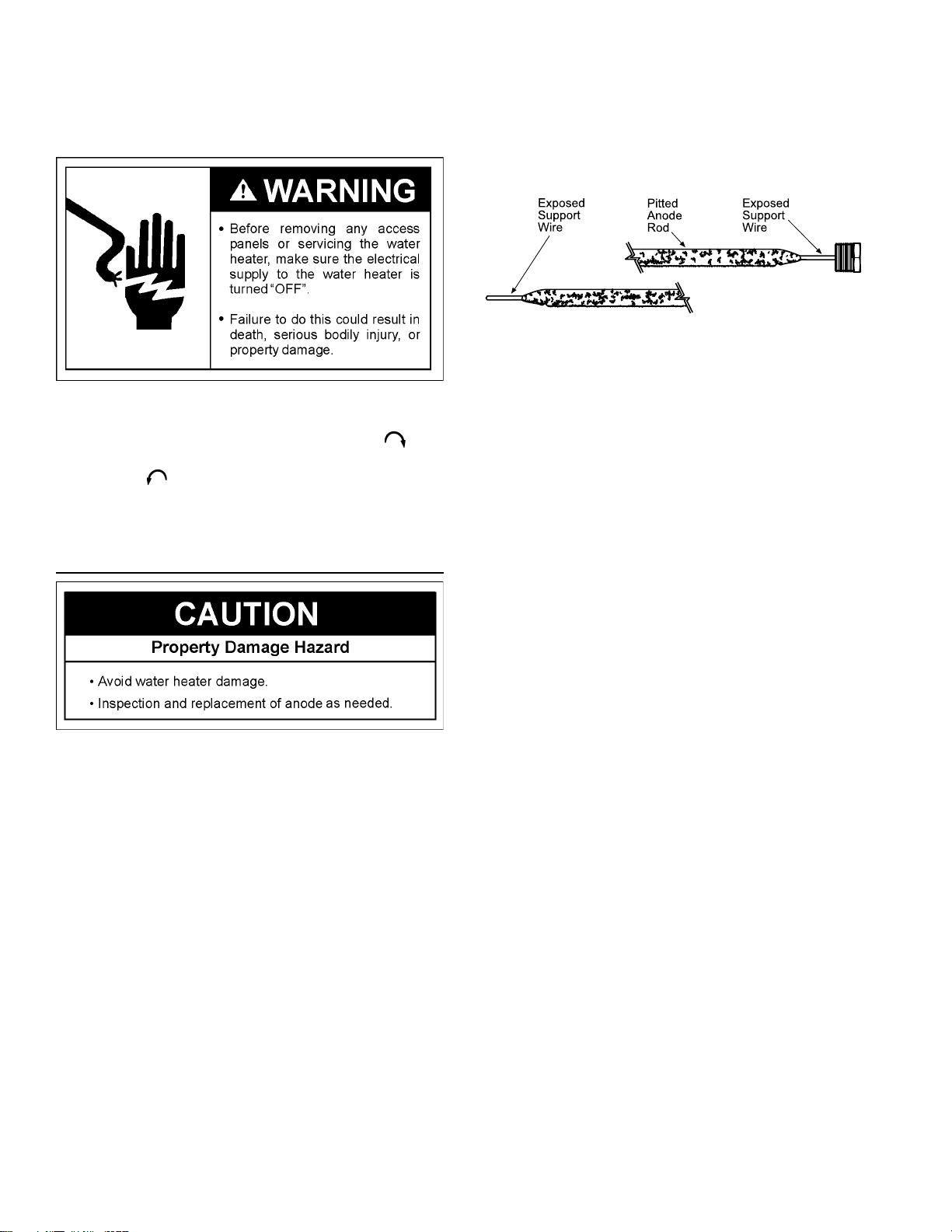
Anode Rod Inspection
Printed on 5/3/2019 1:29 PM CT
) with
years and annually thereafter until the condition of the anode
rod dictates its replacement. NOTE: Artifi cially softened water
requires the anode rod to be inspected annually.
The following are typical (but not all) signs of a depleted
anode rod:
• The majority of the anode rod’s diameter is less than 3/8”.
• Signifi cant sections of the support wire (approx. 1/3 or
more of the anode rod’s length) are visible.
FIGURE 15.
If the anode rod show signs of either or both it should be
replaced. NOTE: Whether re-installing or replacing the anode
rod, check for any leaks and immediately correct if found.
In replacing the anode:
1. Turn off power to the water heater.
2. Shut off the water supply and open a nearby hot water
faucet to depressurize the water tank.
3. Drain approximately 5 gallons of water from tank. (Refer
to “Draining and Flushing” for proper procedures). Close
drain valve.
4. Remove old anode rod.
5. Use Tefl on® tape or approved pipe sealant on threads
and install new anode rod.
6. Turn on water supply and open a nearby hot water faucet
to purge air from water system. Check for any leaks and
immediately correct any if found.
7. Restart the water heater as directed in this manual. See
the Repair Parts Illustration for anode rod location.
Each water heater contains at least one anode rod, which will
slowly deplete (due to electrolysis) prolonging the life of the
water heater by protecting the glass-lined tank from corrosion.
Adverse water quality, hotter water temperatures, high hot
water usage, hydronic heating devices, and water softening
methods can increase the rate of anode rod depletion. Once
the anode rod is depleted, the tank will start to corrode,
eventually developing a leak.
Certain water conditions will cause a reaction between the
anode rod and the water. The most common complaint
associated with the anode rod is a “rotten egg smell” produced
from the presence of hydrogen sulfi de gas dissolved in
the water. IMPORTANT: Do not remove this anode rod
permanently as it will void any warranties. A special anode rod
may be available if water odor or discoloration occurs.
NOTE: This anode rod may reduce but not eliminate water
odor problems. The water supply system may require special
fi ltration equipment from a water conditioning company to
successfully eliminate all water odor problems.
Artifi cially softened water is exceedingly corrosive because the
process substitutes sodium ions for magnesium and calcium
ions.
The anode rod should be inspected after a maximum of three
16

Temperature-Pressure Relief Valve Operation
The temperature-pressure relief valve must be manually operated
at least once a year.
The temperature-pressure relief valve must be manually operated
at least once a year. Caution should be taken to ensure that
(1) no one is in front of or around the outlet of the temperaturepressure relief valve discharge line, and (2) the water manually
discharged will not cause any property damage or bodily injury.
The water may be extremely hot.
Draining and Flushing
The water heater should be drained if being shut down during
freezing temperatures. Also, periodic draining and cleaning of
sediment from the tank may be necessary.
Printed on 5/3/2019 1:29 PM CT
FIGURE 16.
If after manually operating the valve, it fails to completely reset
and continues to release water, immediately close the cold water
inlet to the water heater, follow the draining instructions, and
replace the temperature-pressure relief valve with a new one.
Failure to install and maintain a new properly listed temperaturepressure relief valve will release the manufacturer from any claim
which might result from excessive temperature or pressure.
If the temperature-pressure relief valve on the appliance weeps
or discharges periodically, this may be due to thermal expansion.
Your water heater may have a check valve installed in the water
line or a water meter with a check valve. Consult your local
Sears Service Center for further information. Do not plug the
temperature-pressure relief valve.
1. Before beginning, turn “OFF” the electric power supply to the
water heater.
2. Open a nearby hot water faucet until the water is no longer hot.
3. Close the cold water inlet valve.
4. Connect a hose to the drain valve and terminate it to an
adequate drain or external to the building.
5. Open the water heater drain valve and allow all of the water
to drain from the tank. Flush the tank with water as needed
to remove sediment.
NOTE: If the water heater is going to be shut down and
drained for an extended period, the drain valve should be
left open with hose connected allowing water to terminate
to an adequate drain.
6. Close the drain valve, refi ll the tank, and restart the heater as
directed in this manual.
FIGURE 17.
Never use this water heater unless it is completely full of water.
To prevent damage to the tank and heating element, the tank
must be fi lled with water. Water must fl ow from the hot water
faucet before turning “ON” power.
17
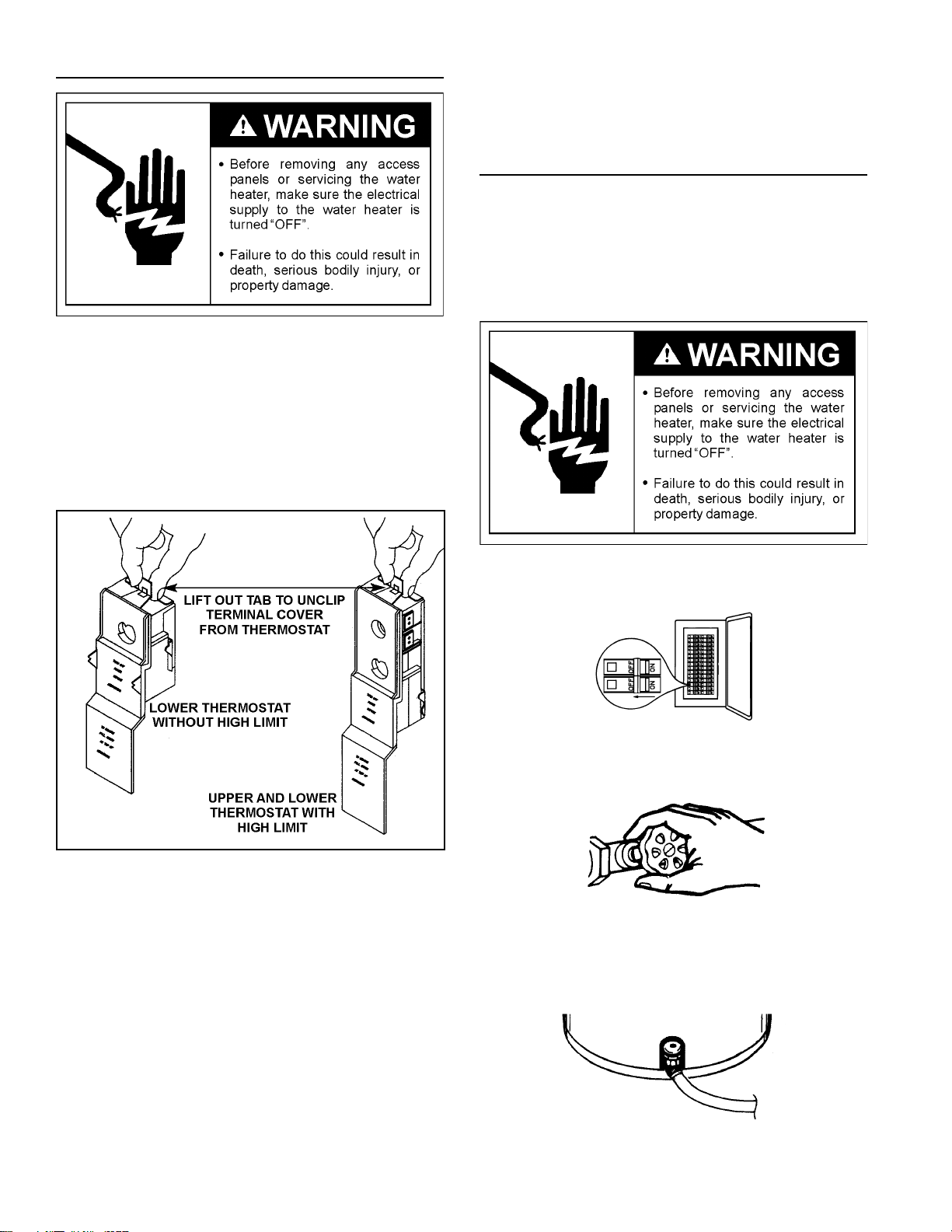
Thermostat Removal/Replacement
1. Turn “OFF” the electrical power to the water heater at the
junction box.
2. Remove the access panel, then fold the insulation back to
expose the thermostat.
3. Lift out the tab as shown below to unclip the terminal cover
from the thermostat. The terminal cover can now be removed
from the thermostat.
9. Replace the insulation to cover the thermostat.
10. Replace access panel, then turn the electric power on.
Element Cleaning/Replacement
NOTE: These instructions are written for element cleaning and
element replacement for the lower element. If it is necessary
to clean or replace the upper element, then repeat these
instructions.
To remove the element from your tank in order to clean or
replace it:
Printed on 5/3/2019 1:29 PM CT
FIGURE 18.
4. Disconnect wires from the thermostat.
5. Remove the thermostat from behind the thermostat
bracket.
6. Place the new thermostat in the bracket making sure it fi ts
fi rmly against the tank.
1. Before beginning, turn “OFF” the electric power supply to
the water heater. After the power has been turned off, open
a nearby hot water faucet until the water is no longer hot.
FIGURE 19.
2. Turn off the water supply to the water heater at the water
Shut-off valve or water meter.
FIGURE 20.
3. Attach a hose to the water heater drain valve and put the
other end in a fl oor drain or outdoors. Open the water heater
drain valve. Open a nearby hot water faucet which will relieve
pressure in the water heater and speed draining.
7. Attach the wires to the new thermostat.
NOTE: Some of the terminals may require straight-in wiring
through an eye-opening. If wires are now looped, recut and
strip wire 3/8” to a straight length and insert.
8. Put plastic terminal cover back in place.
FIGURE 21.
18

The water passing out of the drain valve may be extremely hot.
To avoid being scalded, make sure all connections are tight and
that the water fl ow is directed away from any person.
4. Remove the screw securing the access panel, then remove
the panel.
FIGURE 22.
Printed on 5/3/2019 1:29 PM CT
5. Fold the insulation back to expose the thermostat.
FIGURE 25.
8. Clean the area around the element opening. Remove any
sediment from or around the element opening, inside the
tank.
9. If you are cleaning the element you have removed, do so by
scraping or soaking in vinegar or a de-liming solution.
Replacement elements must (1) be the same voltage and (2)
no greater wattage than listed on the model rating plate affi xed
to the water heater.
FIGURE 23.
6. Lift out the tab as shown to unclip the terminal cover from the
thermostat. The terminal cover can now be removed from
the thermostat.
FIGURE 24.
7. Disconnect the two wires on the element and unscrew the
old element from the tank.
10. A new gasket should be used in all cases to prevent a
possible water leak. (See Element Gasket in the Repair Parts
List Chart). Place the new element gasket on the thread side
of the cleaned or new element and screw into tank, securing
tightly using an element wrench.
FIGURE 26.
11. Close the water heater drain valve by turning the handle to
the right (clockwise). The drain valve is on the lower front of
the water heater.
12. Open the cold water supply valve to the water heater.
NOTE: The cold water supply valve must be left open when the
water heater is in use.
13. To insure complete fi lling of the tank, allow air to exit by
opening the nearest hot water faucet. Allow water to run until
a constant fl ow is obtained. This will let air out of the water
heater and the piping.
19

Never use this water heater unless it is completely full of water.
To prevent damage to the tank and heating element, the tank
must be fi lled with water. Water must fl ow from the hot water
faucet before turning “ON” power.
14. Check element for water leaks. If leakage occurs, tighten
element or repeat steps 2 and 3, remove element and
reposition gasket. Then repeat steps 10 through 14.
15. Reconnect the two wires to the element and then check to
make sure the thermostat remains fi rmly against the surface
of the tank.
FIGURE 27.
16. Replace terminal cover on thermostat making sure that the
Printed on 5/3/2019 1:29 PM CT
locking tabs on the terminal cover are in place.
FIGURE 29.
18. Replace access panel.
19. Turn “ON” electric power to water heater.
FIGURE 30.
Drain Valve Washer Replacement
FIGURE 28.
17. Replace the insulation so that it completely covers the
thermostat and element.
NOTE: For replacement, use a 17/32” x 13/64” x 1/8” thick
washer available at your nearest hardware store. For
ordering a replacement washer, refer to the Repair Parts
List section.
• Before beginning turn “OFF” the electrical power supply to
the water heater.
• Follow Draining instructions. See Draining section.
• Turning counter clockwise, remove the hex cap below the
screw handle.
• Remove the washer and put the new one in place.
• Screw the handle and cap assembly back into the drain valve
and retighten using a wrench. DO NOT OVER TIGHTEN.
20

• Follow Filling the Water Heater instructions in the Installation
Instructions section.
• Check for leaks.
• Turn “ON” electric power to the water heater.
FIGURE 31.
Service
Before calling for repair service, read the Start Up Conditions
and Operational Conditions found in the Troubleshooting section
of this manual.
If a condition persists or you are uncertain about the operation
of the water heater, let a qualifi ed person check it out.
Contact Sears Repair Services at 1-844-553-6667.
Printed on 5/3/2019 1:29 PM CT
21

TROUBLESHOOTING
Start Up Conditions
THERMAL EXPANSION
As water is heated, it expands (thermal expansion). In a closed
system, the volume of water will increase. As the volume of
water increases, there will be a corresponding increase in water
pressure due to thermal expansion. Thermal expansion can
cause premature tank failure (leakage). This type of failure is not
covered under the limited warranty. Thermal expansion can also
cause intermittent temperature-pressure relief valve operation:
water discharged from the valve due to excessive pressure build
up. The temperature-pressure relief valve is not intended for the
constant relief of thermal expansion. This condition is not covered
under the limited warranty.
A properly-sized thermal expansion tank should be installed
on all closed systems to control the harmful effects of thermal
expansion. Thermal expansion tanks are available from Sears
stores and through the Sears Service Centers. Contact the local
Printed on 5/3/2019 1:29 PM CT
plumbing inspector, water supplier and/or the Sears Service
Center regarding the installation of a thermal expansion tank.
Table 2: Thermal Expansion Tank Specifi cations
Model
Number
153.331021 2 8 (203 mm) 12-3/4 (323 mm) 3/4” Male
153.331051 5 11 (279 mm) 14-3/4 (375 mm) 3/4” Male
Tank
Capacity
In Gallons
Table 3: Expansion Tank Sizing Chart
Inlet*
Expansion
Tank
Capacity
Needed
*Highest recorded inlet water pressure in a 24 hour period or
regulated water pressure.
NOTE: Expansion tanks are pre-charged with a 40 psi air
charge. If the inlet water pressure is higher than 40 psi, the
expansion tank’s air pressure must be adjusted to match
that pressure, but must not be higher than 80 psi.
Water
Pressure
40 psi 22255
50 psi 22255
60 psi 22555
70 psi 22555
80 psi 25555
Dimensions
in Inches
Water Heater Capacity (Gallons)
30 40 50 66 82
Pipe
Fitting
On TankDiameter Length
FIGURE 32.
STRANGE SOUNDS
Possible noises due to expansion and contraction of some metal
parts during periods of heat-up and cool-down do not represent
harmful or dangerous conditions.
Operational Conditions
SMELLY WATER
In each glass-lined water heater there is installed one anode
rod (see parts section) for corrosion protection of the tank.
Certain water conditions will cause a reaction between this rod
and the water. The most common complaint associated with the
anode rod is one of a “rotten egg smell.” This odor is derived
from hydrogen sulfi de gas dissolved in the water. The smell is
the result of four factors which must all be present for the odor
to develop:
A. A concentration of sulfate in the supply water.
B. Little or no dissolved oxygen in the water.
C. A sulfate reducing bacteria within the water heater. (This
harmless bacteria is non-toxic to humans.)
D. An excess of active hydrogen in the tank. This is caused by
corrosion protective action of the anode.
Smelly water may be eliminated or reduced in some water heater
models by replacing the anode rod (s) with one of less active
material, and then chlorinating the water heater tank and all hot
water lines. Contact the local Sears Service Center for further
information concerning an Anode Replacement Kit #9001453
and this Chlorination Treatment. Anode replacement and
chlorination of the tank are not covered by the water heater’s
limited warranty.
If the smelly water persists after the anode replacement and
chlorination treatment; then you should consider chlorinating or
aerating your water supply.
22

Do not remove the anode leaving the tank unprotected. By
doing so, all warranty on the water heater tank is voided.
“AIR” IN HOT WATER FAUCETS
HYDROGEN GAS: Hydrogen gas can be produced in a hot
water system that has not been used for a long period of time
(generally two weeks or more). Hydrogen gas is extremely
fl ammable and explosive. To prevent the possibility of injury
under these conditions, we recommend the hot water faucet
be opened for several minutes at the kitchen sink before any
electrical appliances which are connected to the hot water
system are used (such as a dishwasher or washing machine).
If hydrogen gas is present, there will probably be an unusual
sound similar to air escaping through the pipe as the hot water
faucet is opened. There must be no smoking or open fl ame near
the faucet at the time it is open.
RUMBLING NOISE
In some water areas, scale or mineral deposits will build up on
Printed on 5/3/2019 1:29 PM CT
your heating elements. This buildup will cause a rumbling noise.
Follow Element Cleaning/Replacement instructions to clean and
replace the elements.
HIGH TEMPERATURE SHUT OFF SYSTEM
The water heater has a high limit shut off system with a reset
button located on the thermostat.
Follow the resetting instructions which refer to the high limit
behind the access panel.
1. Before beginning, turn “OFF” electrical power supply to the
water heater.
2. Remove the screw securing the access panel, then remove
the panel.
3. Fold the insulation back to expose the thermostat.
4. Reset the high limit by pushing in the red button marked
“RESET”.
FIGURE 34.
5. Replace the insulation so that it completely covers the
thermostat and element.
6. Replace the access panel.
7. Turn “ON” electric power to the water heater.
If the high limit must be reset again, call Sears Service Department
to fi nd out why the high limit turned “OFF” the electric power
NOT ENOUGH OR NO HOT WATER
1. In a new installation, the water heater may not be properly
connected. Make sure the cold water supply valve is open.
Review and check piping installation. Make sure that the
cold water line is connected to the cold water inlet to the
water heater and the hot water line to the hot water outlet
on the water heater.
2. Make sure the electrical supply to your water heater is “ON”.
3. Check for loose or blown fuses in your water heater circuit.
Circuit breakers weaken with age and may not handle their
rated load and should be replaced.
4. Make certain the disconnect switch, if used, is in the “ON”
position.
5. Check to see the electric service to your house has not been
interrupted. If this is the case, contact the electric company.
6. Is the thermostat set to the desired temperature? See
Temperature Regulation section.
7. If you had experienced very hot water and now no hot water,
the problem may be due to the high temperature shut off
system. See High Temperature Shut Off System in the
Troubleshooting section.
8. During very cold weather, the incoming water will also be
colder and it will require a longer time to become heated.
9. The hot water usage may exceed the capacity of the water
heater. If so, wait for water heater to recover after abnormal
demand. Also examine pipes and faucets for possible water
leaks.
10. If you can not determine the problem, then call the Sears
Service Department.
FIGURE 33.
WATER IS TOO HOT
Adjust the thermostat to a lower setting. See the Temperature
Regulation section.
23

LEAKAGE CHECKPOINTS
Never use this water heater unless it is completely full of water.
To prevent damage to the tank and heating element, the tank
must be fi lled with water. The water must fl ow from the hot water
faucet before turning “ON” power.
A. *Condensation may be seen on pipes in humid weather or
pipe connections may be leaking.
B. Small amounts of water from the temperature-pressure relief
valve may be due to thermal expansion or high water pressure
in your area.
C. *The temperature-pressure relief valve may be leaking at the
tank fi tting.
D. *The element may be leaking at the tank fi tting.
Printed on 5/3/2019 1:29 PM CT
Read this manual fi rst. Then before checking the water heater
make sure the electric supply has been turned “OFF”, and never
turn the electric supply “on” before the tank is completely full of
water.
Use this guide to check a “Leaking” water heater. Many suspected
“Leakers” are not leaking tanks. Often the source of the water
can be found and corrected.
If you are not thoroughly familiar with electric codes, the water
heater, and safety practices, contact your local Sears Service
Center to check the water heater.
FIGURE 35.
Turn electrical power “OFF”, remove access panel and insulation
cap with handle. If leaking around element, follow proper draining
instructions and remove element. Reposition or replace gasket
on element. Place element into opening and tighten securely.
Then follow Filling the Water Heater instructions in the Installation
Instructions section.
E. Water from drain valve may be due to the valve being opened
slightly
F. *The drain valve may be leaking at the tank fi tting.
G. Water in the water heater bottom or on the fl oor may be
from condensation, loose connections or the temperaturepressure relief valve. DO NOT replace the water heater until
a full inspection of all possible water sources is made and
necessary corrective steps taken.
Leakage from other appliances, water lines, or ground seepage
should also be checked.
* To check where threaded portion enters tank, insert
cotton swab between jacket opening and fitting. If
cotton is wet, follow Draining instructions in the Service
and Adjustment section and then remove fi tting. Put
pipe dope or tefl on tape on the threads and replace.
Then follow Filling the Water Heater instructions in the
Installation Instructions section.
24

REPAIR PARTS LIST
KENMORE 6
ELECTRIC WATER HEATERS
MODEL NUMBERS
153.586320 30 Gallon
153.586311 30 gallon
153.586401 40 Gallon
153.586501 50 Gallon
4
11
12
10
13
19
16
15
18
5
20
17
7
14
3
9
2
6
1
Key
Printed on 5/3/2019 1:29 PM CT
No. Part Description
1 Drain Valve 100158121 100158121 100158121 100158121
2 Element Gasket 100108379 100108379 100108379 100108379
3 Element Gasket 100108379 100108379 100108379 100108379
4
Heat Trap Nipple
5
Lower Access Panel
6 Lower Element 4500 Watts 100108290 100108290 100108290 100108290
7
Lower Thermostat w/Hi-Limit
8 Manual # 100281900 100281900 100281900 100281900
9 Model Rating Plate - - - - - - - - - - - - - - - - - - - - - - - - - - - - - - - - - - - -
10 Primary Anode Rod
11 Combination Heat Trap Nipple/Anode 100109621 - - - - - - - - - - - - - - - - - - - - - - - - - - 12 Dip Tube (includes Nipple with Heat Trap) 100265092 100269972 100273983 100210050
13 Temperature and Pressure Relief Valve 100108599 100108599 100108599 100108599
14 Terminal Cover (Lower)
15 Terminal Cover (Upper) 100108799 100108799 100108799 100108799
16 Thermostat Bracket 100109597 100109597 100109597 100109597
17 Thermostat Bracket 100109597 100109597 100109597 100109597
18 Upper Access Panel
19 Upper Element 4500 Watts 100108290 100108290 100108290 100108290
20 Upper Thermostat w/Hi-Limit 100108683 100108683 100108683 100108683
21 Hot Outlet Tube # - - - - - - - - - 100281521 100281522 100269973
22 Secondary Anode # - - - - - - - - - 100111073 - - - - - - - - - - - - - - - - - -
* These parts are also available at most Sears retail stores. ** Also available at most hardware stores.
†† Refer to Wiring Diagram section for verifi cation. #Not illustrated.
Now that you have purchased this water heater, should a need ever
exist for repair parts or service, simply contact any Sears Service
Center or call 1-844-553-6667. Be sure to provide all pertinent facts
when you call or visit.
THIS IS A REPAIR PARTS LIST, NOT A PACKING LIST.
Model No.
153.586320 153.586311 153.586401 153.586501
100109621 - - - - - - - - - - - - - - - - - - 100109621
100109599 100109599 100109599 100109599
100108421 100108421 100108421 100108421
100109624 100111073 100108260 100108260
100108743 100108743 100108743 100108743
100109599 100109599 100109599 100109599
WHEN ORDERING REPAIR PARTS, ALWAYS GIVE THE
FOLLOWING INFORMATION:
• MODEL NUMBER
• PART NUMBER
• SERIAL NUMBER
• PART DESCRIPTION
25

REPAIR PARTS LIST
KENMORE 6
ELECTRIC WATER HEATERS
MODEL NUMBERS
153.586511 50 Gallon Medium
153.586411 40 Gallon Medium
4
11
12
10
13
19
16
15
18
5
20
17
23
17
7
14
3
9
2
6
3
1
Key
Printed on 5/3/2019 1:29 PM CT
No. Part Description
1 Drain Valve 9009060 9009060
2
Element Gasket
153.586511 153.586411
Model No.
9000308 9000308
3 Element Gasket 9000308 9000308
4 Heat Trap Nipple
9003936 9003936
5 Lower Access Panel 9003900 9003900
6
Lower Element 4500 Watts
9000095 9000095
7 Lower Thermostat w/Hi-Limit 9000507 9000507
8 Manual # 100281900 100281900
9 Model Rating Plate - - - - - - - - - - - - - - - - - -
10 Primary Anode Rod 9000029 9003944
11 Combination Heat Trap Nipple/Anode
9003936 9003936
12 Dip Tube (includes Nipple with Heat Trap) 9002403 9002403
13 Temperature and Pressure Relief Valve 9001583 9001583
14 Terminal Cover (Lower)
9002276 9002276
15 Terminal Cover (Upper) 9002438 9002438
16 Thermostat Bracket 9003898 9003898
17 Thermostat Bracket
9003898 9003898
18 Upper Access Panel 9003900 9003900
19 Upper Element 4500 Watts
9000095 9000095
20 Upper Thermostat w/Hi-Limit 9001954 9001954
* These parts are also available at most Sears retail stores. ** Also available at most hardware stores.
†† Refer to Wiring Diagram section for verifi cation. #Not illustrated.
Now that you have purchased this water heater, should a need ever
exist for repair parts or service, simply contact any Sears Service
Center or call 1-844-553-6667. Be sure to provide all pertinent facts
when you call or visit.
THIS IS A REPAIR PARTS LIST, NOT A PACKING LIST.
WHEN ORDERING REPAIR PARTS, ALWAYS GIVE THE
FOLLOWING INFORMATION:
• MODEL NUMBER
• PART NUMBER
• SERIAL NUMBER
• PART DESCRIPTION
26

NOTES
Printed on 5/3/2019 1:29 PM CT
27

NOTES
Printed on 5/3/2019 1:29 PM CT
28

NOTES
Printed on 5/3/2019 1:29 PM CT
29

NOTES
Printed on 5/3/2019 1:29 PM CT
30

NOTES
Printed on 5/3/2019 1:29 PM CT
31

Kenmore ®
®
Customer Care Hotline
To schedule repair service or order parts
Para pedir servicio o ordenar piezas
1-844-553-6667
www. kenmore. com
Printed on 5/3/2019 1:29 PM CT
For service in Canada Au Canada pour service
1-800-469-4663
32
 Loading...