

Kenmore 153339530, 153339492, 153339270 Owner’s Manual
Owner's Manual
POWER MISERTM 9
GAS WATER HEATER
FOR POTABLE WATER HEATING ONLY.
NOT SUITABLE FOR SPACE HEATING.
NOT FOR USE IN MOBILE HOMES.
MODEL NO.
153.339270
153.339492
153.339530
40 Gallon Short
40 Gallon Tall
50 Gallon Tall
• Safety Instructions
• Installation
• Operation
• Care and Maintenance
• Troubleshooting
• Parts List
This water heater complies with ANSI Z21.10.1-
current edition regarding the accidental or
unintended ignition of flammable vapors, such
as those emitted by gasoline.
Read and understand instruction
manual and safety messages
before installing, operating or
servicing this water heater.
Failure to follow instructions and
safety messages could result in
death or serious injury.
Instruction manual must remain
with water heater.
For Your Safety
AN ODORANT ISADDED TO THE GAS USED BY THIS WATER HEATER.
WARNING: If the information in these
instructions is not followed exactly, a fire
or explosion may result causing property
damage, personal injury or death.
m Do not store or use gasoline or other
flammable vapors and liquids in the
vicinity of this or any other appliance.
-- WHAT TO DO IF YOU SMELL GAS:
• Do not try to light any appliance.
• Do not touch any electrical switch; do
not use any phone in your building.
• Immediately call your gas supplier
from a neighbor's phone. Follow the
gas supplier's instructions.
• If you cannot reach your gas supplier,
call the fire department.
Si no puede leer o entender el ingles y necesita el manual de
instrucciones en espaSol, puede solicitarlo al 1-800-821-2017. NO
TRATE DE INSTALAR UOPERAR ESTE CALENTADOR DE AGUA
Sl NO ENTIENDE LAS INSTRUCCIONES. No hacer caso de esta
advertencia podria originar lesiones graves o mortales.
m lnstallation and service must be
performed by a qualified installer,
service agency or the gas supplier.
Sears, Roebuck and Co., Hoffman Estates, IL 60179 U.S.A
PRINTED IN THE U.S.A 1208 www.sears.com PART NO. 315424-000
Your safety and the safety of others is extremely important in the installation, use and servicing of this water heater.
Many safety-related messages and instructions have been provided in this manual and on your own water heater to warn you and others of
a potential injury hazard. Read and obey all safety messages and instructions throughout this manual. It is very important that the meaning
of each safety message is understood by you and others who install, use or service this water heater.
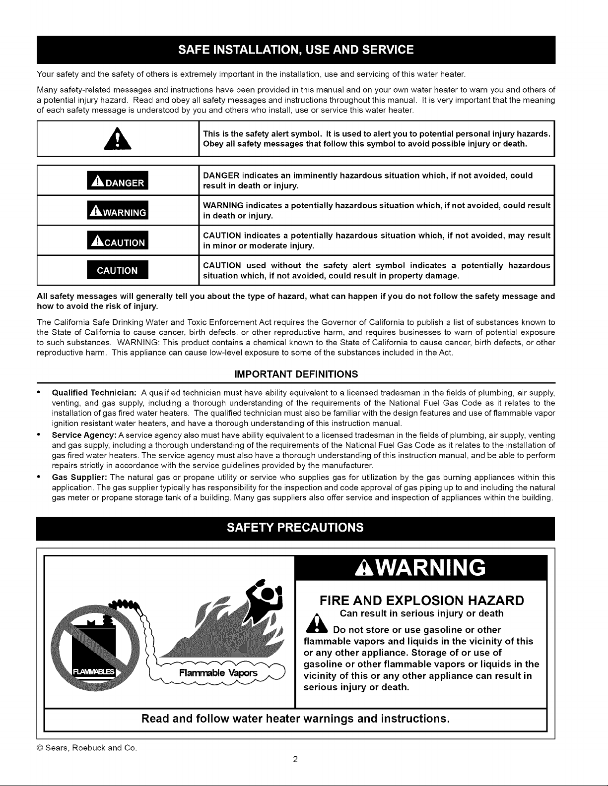
n
,_ I This is the safety alert symbol, it is used to alert you to potential personal injury hazards.
Obey all safety messages that follow this symbol to avoid possible injury or death.
I
DANGER indicates an imminently hazardous situation which, if not avoided, could
result in death or injury.
WARNING indicates a potentially hazardous situation which, if not avoided, could result
in death or injury.
CAUTION indicates a potentially hazardous situation which, if not avoided, may result
in minor or moderate injury.
CAUTION used without the safety alert symbol indicates a potentially hazardous
situation which, if not avoided, could result inproperty damage.
All safety messages will generally tell you about the type of hazard, what can happen if you do not follow the safety message and
how to avoid the risk of injury.
The California Safe Drinking Water and Toxic Enforcement Act requires the Governor of California to publish a list of substances known to
the State of California to cause cancer, birth defects, or other reproductive harm, and requires businesses to warn of potential exposure
to such substances. WARNING: This product contains a chemical known to the State of California to cause cancer, birth defects, or other
reproductive harm. This appliance can cause low-level exposure to some of the substances included in the Act.
IMPORTANT DEFINITIONS
• Qualified Technician: A qualified technician must have ability equivalent to a licensed tradesman in the fields of plumbing, air supply,
venting, and gas supply, including a thorough understanding of the requirements of the National Fuel Gas Code as it relates to the
installation of gas fired water heaters The qualified technician must also be familiar with the design features and use of flammable vapor
ignition resistant water heaters, and have a thorough understanding of this instruction manual
• Service Agency: A service agency also must have ability equivalent to a licensed tradesman in the fields of plumbing, air supply, venting
and gas supply, including a thorough understanding of the requirements of the National Fuel Gas Code as it relates to the installation of
gas fired water heaters The service agency must also have a thorough understanding of this instruction manual, and be able to perform
repairs strictly in accordance with the service guidelines provided by the manufacturer
• Gas Supplier: The natural gas or propane utility or service who supplies gas for utilization by the gas burning appliances within this
application The gas supplier typically has responsibility for the inspection and code approval of gas piping up to and including the natural
gas meter or propane storage tank of a building Many gas suppliers also offer service and inspection of appliances within the building
© Sears, Roebuck and Co.
FIRE AND EXPLOSION HAZARD
Can result in serious injury or death
Do not store or use gasoline or other
flammable vapors and liquids in the vicinity of this
or any other appliance. Storage of or use of
gasoline or other flammable vapors or liquids in the
vicinity of this or any other appliance can result in
serious injury or death.
Read and follow water heater warnings and instructions.
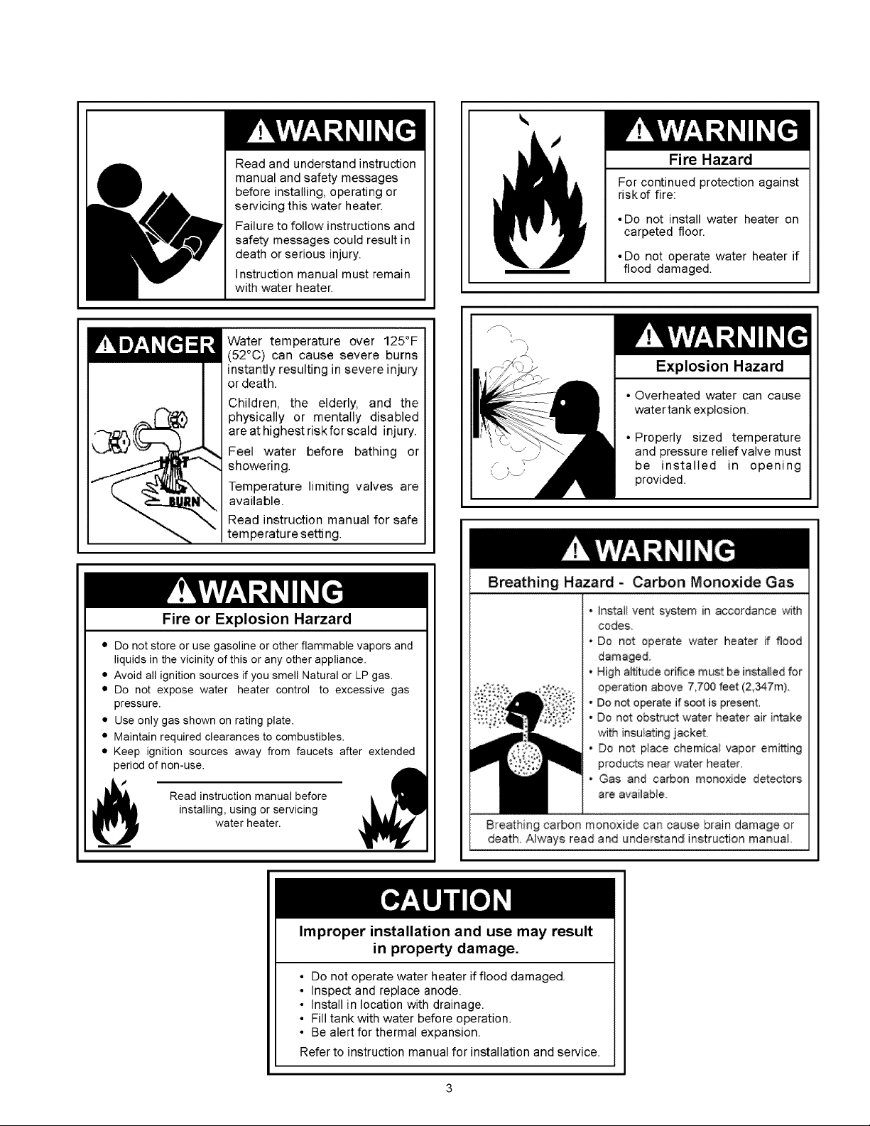
Read and understand instruction
manual and safety messages
before installing, operating or
servicing this water heater.
Failure to follow instructions and
safety messages could result in
death or serious injury.
Instruction manual must remain
with water heater.
Water temperature over 125°F
(52°C) can cause severe burns
instantly resulting in severe injury
or death.
Children, the elderly, and the
physically or mentally disabled
are at highest riskforscald injury.
Feel water before bathing or
showering.
Temperature limiting valves are
available.
Read instruction manual for safe
temperature setting
Fire Hazard
For continued protection against
riskof fire:
• Do not install water heater on
carpeted floor.
• Do not operate water heater if
flood damaged.
Explosion Hazard
• Overheated water can cause
watertank explosion.
• Properly sized temperature
and pressure relief valve must
be installed in opening
provided.
Fire or Explosion Harzard
• Do not store or use gasoline or other flammable vapors and
liquids in the vicinity of this or any other appliance.
• Avoid all ignition sources if you smell Natural or LP gas.
• Do not expose water heater control to excessive gas
pressure.
• Use only gas shown on rating plate.
• Maintain required clearances to combustibles.
• Keep ignition sources away from faucets after extended
period of non-use.
installing, using or servicing
Read instruction manual before
water heater.
Improper installation and use may result
in property damage.
• Do not operate water heater if flood damaged.
• Inspect and replace anode.
• Install in location with drainage.
• Fill tank with water before operation.
• Be alert for thermal expansion.
Refer to instructionmanual for installation and service.
Breathing Hazard - Carbon Monoxide Gas
• Instaii vent system in accordance with
cedes.
- Do not operate water heater if flood
damaged.
• High altitude orifice must be installed for
opera, on above 7.700 feet (2.347m).
, Do not operate if s_t is present.
• Do not obstru_ water hea_er air intake
with insulating jacket.
, Do not place chemical vapor emi_Jng
produc_s near water heater.
, Gas and carbon monoxide detectors
are available
Breathing carbon monoxide car cause brain damage or
death Always read and understand instruction manual_
SAFE INSTALLATION, USE AND SERVICE ................................................................................................. 2
SAFETY PRECAUTIONS ........................................................................................................................... 2-3
PRODUCT WARRANTY ................................................................................................................................ 6
CUSTOMER RESPONSIBILITIES ................................................................................................................. 7
PRODUCT SPECIFICATIONS ...................................................................................................................... 8
MATERIALS AND BASIC TOOLS NEEDED .................................................................................................. 9
TYPICAL INSTALLATION ............................................................................................................................ 10
IMPORTANT INFORMATION ABOUT THIS WATER HEATER .................................................................... 11
Installation Checklist ................................................................................................................................................ 11
INSTALLATION INSTRUCTIONS ........................................................................................................... 12-15
Removing the Old Water Heater ............................................................................................................................. 12
Location Requirements ........................................................................................................................................... 13
Site Location ........................................................................................................................................................... 13
Insulation Blankets .................................................................................................................................................. 14
Clearances and Accessibility ............................................................................................................................. 14-15
Filling the Water Heater .......................................................................................................................................... 15
GAS SUPPLY .......................................................................................................................................... 15-16
Gas Requirements .................................................................................................................................................. 15
Gas Piping .............................................................................................................................................................. 15
Gas Pressure .......................................................................................................................................................... 16
Gas Pressure Testing .............................................................................................................................................. 16
LP Gas Only ............................................................................................................................................................ 16
COMBUSTION AIR SUPPLY & VENTILATION ...................................................................................... 17-20
Unconfined Space ................................................................................................................................................... 17
Confined Space ...................................................................................................................................................... 17
All Air from Inside the Building ........................................................................................................................... 17-18
All Air from Outdoors ............................................................................................................................................... 18
Louvers and Grilles ............................................................................................................................................ 18-19
Vent Pipe System ................................................................................................................................................... 19
Draft Hood Installation ............................................................................................................................................ 19
Vent Pipe Size ........................................................................................................................................................ 19
Vent Connectors ................................................................................................................................................ 19-20
Chimney Connection ............................................................................................................................................... 20
Vertical Exhaust Gas Vent ...................................................................................................................................... 20
WATER SYSTEM PIPING ....................................................................................................................... 21-22
Piping Installation .................................................................................................................................................... 21
Closed System/Thermal Expansion ........................................................................................................................ 22
Temperature and Pressure Relief Valve ................................................................................................................. 22
T&P Relief Valve and Pipe Insulation ........................................................................................................................ 22
OPERATINGYOURWATERHEATER...................................................................................................23-25
LightingInstructions................................................................................................................................................23
CheckingtheDraft..................................................................................................................................................24
BurnerFlames........................................................................................................................................................24
EmergencyShutDown...........................................................................................................................................24
WaterTemperatureRegulation..........................................................................................................................24-25
SERVICEANDADJUSTMENT...............................................................................................................26-28
Tank(Sediment)Cleaning......................................................................................................................................26
VentSystemInspection..........................................................................................................................................26
BurnerInspection....................................................................................................................................................26
BurnerCleaning......................................................................................................................................................26
Housekeeping.........................................................................................................................................................27
AnodeRodInspection............................................................................................................................................27
Temperature-PressureReliefValveOperation.......................................................................................................27
DrainingandFlushing........................................................................................................................................27-28
Service....................................................................................................................................................................28
MAINTENANCEOFYOURWATERHEATER........................................................................................29-32
ReplacementParts.................................................................................................................................................29
ExternalInspection& CleaningoftheBase-RingFilter.........................................................................................29
RemovingtheManifold/BurnerAssembly...............................................................................................................29
RemovingtheBurnerfromtheManifold/BurnerAssembly....................................................................................29
ReplacingtheThermocouple.............................................................................................................................29-30
ReplacingthePilot/PilotTubeAssembly...............................................................................................................30
CleaningtheCombustionChamberandFlame-arrestor........................................................................................30
ReplacingtheManifold/BurnerAssembly...............................................................................................................31
PiezoelectricIgniterSystem...................................................................................................................................31
TestingtheIgniterSystem......................................................................................................................................32
RemovingandReplacingtheGasControlValve/Thermostat................................................................................32
FVlRSystemOperationalChecklist.......................................................................................................................32
TROUBLESHOOTINGGUIDE................................................................................................................33-35
StartUpConditions............................................................................................................................................33-34
OperationalConditions......................................................................................................................................34-35
TROUBLESHOOTINGCHART...............................................................................................................36-37
PILOTLIGHTTROUBLESHOOTINGFLOWCHART...................................................................................38
PARTSORDERLIST...................................................................................................................................39
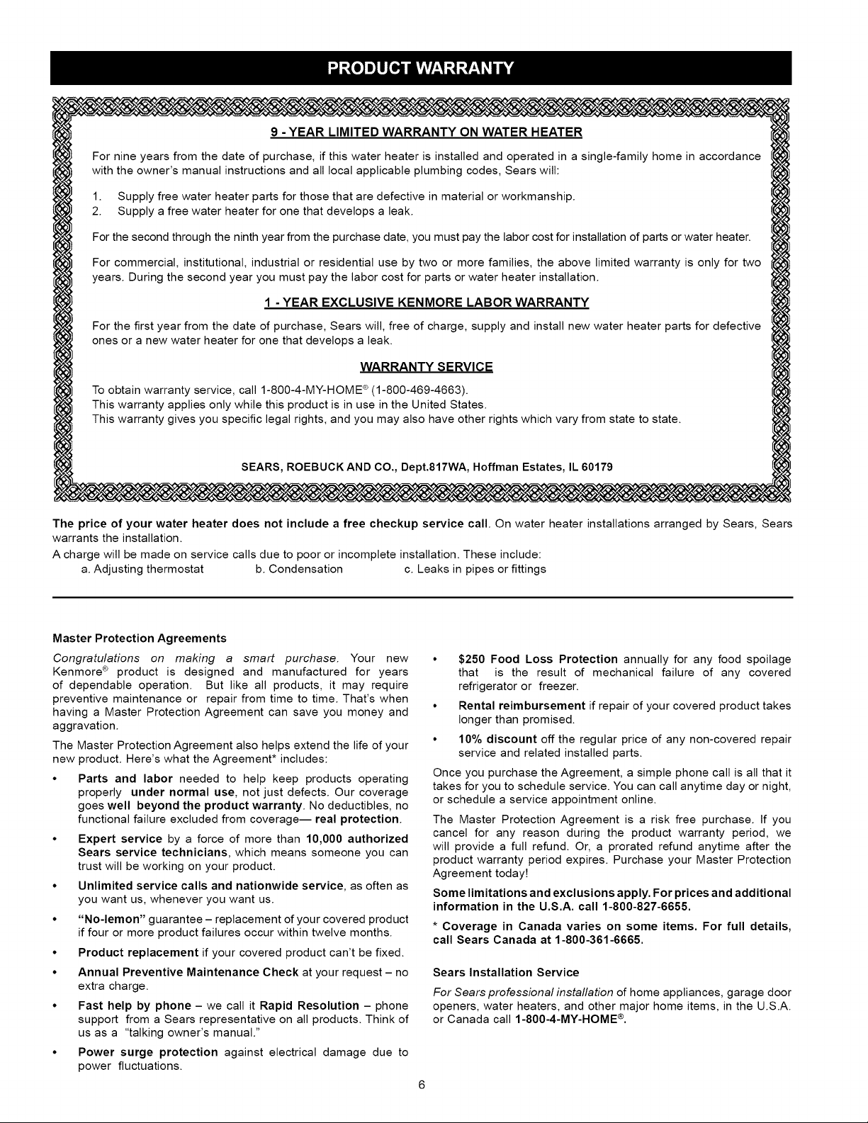
9 - YEAR LIMITED WARRANTY ON WATER HEATER
For nine years from the date of purchase, if this water heater is installed and operated in a single-family home in accordance
with the owner's manual instructions and all local applicable plumbing codes, Sears will:
1. Supply free water heater parts for those that are defective in material or workmanship.
2. Supply a free water heater for one that develops a leak.
For the second through the ninth year from the purchase date, you must pay the labor cost for installation of parts or water heater.
For commercial, institutional, industrial or residential use by two or more families, the above limited warranty is only for two
years. During the second year you must pay the labor cost for parts or water heater installation.
1 - YEAR EXCLUSIVE KENMORE LABOR WARRANTY
For the first year from the date of purchase, Sears will, free of charge, supply and install new water heater parts for defective
ones or a new water heater for one that develops a leak.
WARRANTY SERVICE
To obtain warranty service, call 1-800-4-MY-HOME ® (1-800-469-4663).
This warranty applies only while this product is in use in the United States.
This warranty gives you specific legal rights, and you may also have other rights which vary from state to state.
SEARS, ROEBUCK AND CO., Dept.817WA, Hoffman Estates, IL 60179
The price of your water heater does not include a free checkup service call. On water heater installations arranged by Sears, Sears
warrants the installation.
A charge will be made on service calls due to poor or incomplete installation. These include:
a. Adjusting thermostat b. Condensation c. Leaks in pipes or fittings
Master Protection Agreements
Congratulations on making a smart purchase. Your new
Kenmore ® product is designed and manufactured for years
of dependable operation. But like all products, it may require
preventive maintenance or repair from time to time. That's when
having a Master Protection Agreement can save you money and
aggravation.
The Master Protection Agreement also helps extend the life of your
new product. Here's what the Agreement* includes:
• Parts and labor needed to help keep products operating
properly under normal use, not just defects. Our coverage
goes well beyond the product warranty. No deductibles, no
functional failure excluded from coverage-- real protection.
• Expert service by a force of more than 10,000 authorized
Sears service technicians, which means someone you can
trust will be working on your product.
• Unlimited service calls and nationwide service, as often as
you want us, whenever you want us.
• "No-lemon" guarantee - replacement of your covered product
if four or more product failures occur within twelve months.
• Product replacement if your covered product can't be fixed.
• Annual Preventive Maintenance Check at your request - no
extra charge.
• Fast help by phone - we call it Rapid Resolution - phone
support from a Sears representative on all products. Think of
us as a "talking owner's manual."
• Power surge protection against electrical damage due to
power fluctuations.
• $250 Food Loss Protection annually for any food spoilage
that is the result of mechanical failure of any covered
refrigerator or freezer.
• Rental reimbursement if repair of your covered product takes
longer than promised.
• 10% discount off the regular price of any non-covered repair
service and related installed parts.
Once you purchase the Agreement, a simple phone call is all that it
takes for you to schedule service. You can call anytime day or night,
or schedule a service appointment online.
The Master Protection Agreement is a risk free purchase. If you
cancel for any reason during the product warranty period, we
will provide a full refund. Or, a prorated refund anytime after the
product warranty period expires. Purchase your Master Protection
Agreement today!
Some limitations and exclusions apply. For prices and additional
information in the U.S.A. call 1-800-827-6655.
* Coverage in Canada varies on some items. For full details,
call Sears Canada at 1-800-361-6665.
Sears Installation Service
For Sears professional installation of home appliances, garage door
openers, water heaters, and other major home items, in the U.S.A.
or Canada call 1-800-4-MY-HOME ®.
ThankYouforpurchasingaKenmorewaterheater.Properlyinstalled
andmaintained,itshouldgiveyouyearsoftroublefreeservice.If
youshoulddecidethatyouwantthenewwaterheaterprofessionally
installedbySearscall1-800-4-MY-HOME®.Theywillarrangefor
prompt,qualityinstallationbySearsauthorizedcontractors.
Abbreviations Found In This Instruction Manual:
• CSA- Canadian Standards Association
• ANSI- American National Standards Institute
• N FPA- National Fire Protection Association
• ASME - American Society of Mechanical Engineers
• GAMA- Gas Appliance Manufacturers Association
Massachusetts Code requires this water heater to be installed in
accordance with Massachusetts 248-CMR 2.00: State Plumbing
Code and 248-CMR 5.00.
Complies with 40 Ng/J NOx requirements of Texas and most
California AQM Districts.
Excessive Weight Hazard
Use two or more people to move and install the water heater.
Failure to do so can result in injury (including back injury).
Important Information About This Water Heater:
This gas water heater was manufactured to voluntary safety
standards to reduce the likelihood of a flammable vapor ignition
incident. New technology used in meeting these standards makes this
product more sensitive to installation errors or improper installation
environments. Please review the Installation Checklist found at the
end of the installation instructions section and make any required
installation upgrades or changes.
This manual contains instructions for the installation, operation,
and maintenance of the gas-fired water heater, tt also contains
warnings through out the manual that you must read and be aware
of. All warnings and all instructions are essential to the proper
operation of the water heater and your safety. Since we cannot put
everything on the first few pages, READ THE ENTIRE MANUAL
BEFORE ATTEMPTING TO INSTALL OR OPERATE THE WATER
HEATER.
The installation must conform with these instructions and the
local code authority having jurisdiction. In the absence of local
codes, installations shall comply with the following:
In the United States: The National Fuel Gas CodeANSI Z223.1/
NFPA 54. This publication is available from the Canadian
StandardsAssociation, 8501 East Pleasant Valley Rd, Cleveland
Ohio 44131, or The National Fire Protection Association, 1
Batterymarch Park, Quincy, MA 02269.
IMPORTANT: Do not remove any permanent instructions, labels, or
the data label from either the outside of the water heater or on the
inside of water heater panels.
• Remove exterior packaging and place installation components
aside.
• Inspect all parts for damage prior to installation and
start-up.
• Completely read all instructions before attempting to assemble
and install this product.
• After installation, dispose of/recycle all packaging materials.
• If after reading this manual you have any questions or do not
understand any portion of the instructions, call the Sears Service
Center.
Carefully plan the place where you are going to put the water heater.
Correct combustion, vent action, and vent pipe installation are
very important in preventing death from possible carbon monoxide
poisoning and fires. See Figure 1.
• Examine the location to ensure the water heater complies with
the Installation Instructions section in this manual.
For California installation, this water heater must be braced,
anchored, or strapped to avoid falling or moving during an
earthquake. See instructions for correct installation procedures.
Instructions may be obtained from California's Office of the
State Architect, 1102 Q Street, Suite 5100, Sacramento, CA
95811. Instructions can also be downloaded to your computer
at www.dsa.dgs.ca.gov/Pubs.
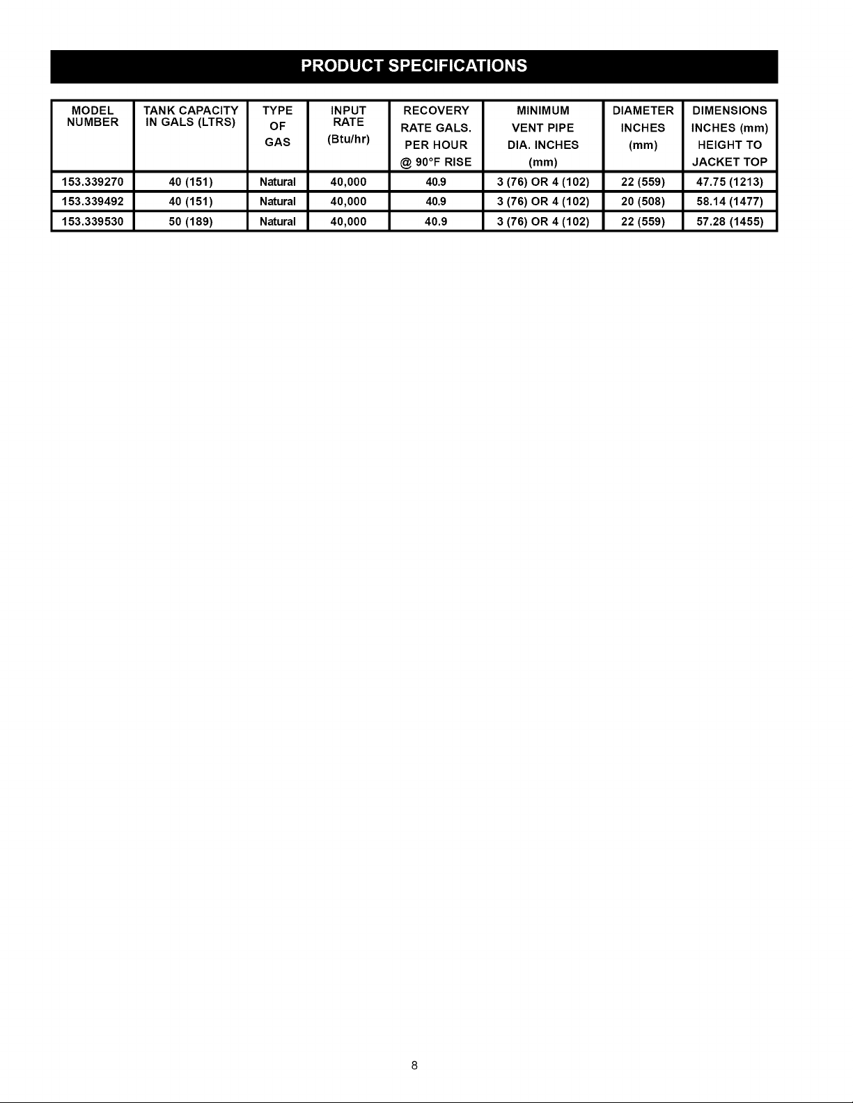
MODEL TANK CAPACITY TYPE INPUT RECOVERY MINIMUM DIAMETER DIMENSIONS
NUMBER IN GALS (LTRS) OF RATE
GAS (Btu/hr) PER HOUR DIA. INCHES (mm) HEIGHT TO
153.339270 40 (151) Natural 40,000 40.9 3 (76) OR 4 (102) 22 (559) 47.75 (1213)
153.339492 40 (151) Natural 40,000 40.9 3 (76) OR 4 (102) 20 (508) 58.14 (1477)
153.339530 50 (189) Natural 40,000 40.9 3 (76) OR 4 (102) 22 (559) 57.28 (1455)
RATE GALS. VENT PIPE INCHES INCHES (mm)
@ 90°F RISE (mm) JACKET TOP
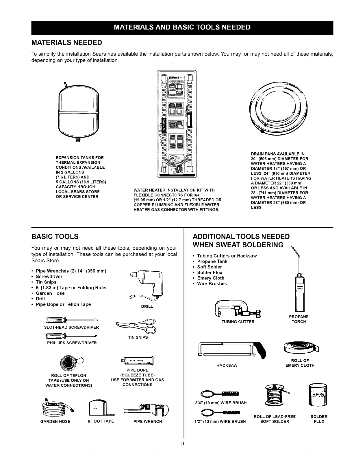
MATERIALS NEEDED
To simplify the installation Sears has available the installation parts shown below. You may or may not need all of these materials,
depending on your type of installation.
EXPANSION TANKS FOR
THERMAL EXPANSION
CONDITIONS AVAILABLE
IN 2 GALLONS
(7.6 LITERS) AND
5 GALLONS (18.9 LITERS)
CAPACITY HROUGH
LOCAL SEARS STORE
OR SERVICE CENTER.
WATER HEATER INSTALLATION KIT WITH
FLEXIBLE CONNECTORS FOR 3/4"
(19.05 ram) OR 1/2" (12.7 mm) THREADED OR
COPPER PLUMBING AND FLEXIBLE WATER
HEATER GAS CONNECTOR WITH FITTINGS.
BASIC TOOLS
You may or may not need all these tools, depending on your
type of installation. These tools can be purchased at your local
Sears Store.
• Pipe Wrenches (2) 14" (356 mm)
• Screwdriver
• Tin Snips
• 6' (1.82 m) Tape or Folding Ruler
• Garden Hose
• Drill
• Pipe Dope or Teflon Tape
SLOT-HEAD SCREWDRIVER
DRILL
DRAIN PANS AVAILABLE IN
20" (508 ram) DIAMETER FOR
WATER HEATERS HAVING A
DIAMETER 18" (457 mm) OR
LESS, 24" (610mm) DIAMETER
FOR WATER HEATERS HAVING
A DIAMETER 22" (559 mm)
OR LESS AND AVAILABLE IN
28" (711 mm) DIAMETER FOR
WATER HEATERS HAVING A
DIAMETER 26" (660 mm) OR
LESS.
ADDITIONAL TOOLS NEEDED
WHEN SWEAT SOLDERING
• Tubing Cutters or Hacksaw
• Propane Tank
• Soft Solder
• Solder Flux
• Emery Cloth
• Wire Brushes
TUBING CUTTER
\
1
PROPANE
TORCH
PHILLIPS SCREWDRIVER
ROLL OF TEFLON
TAPE (USE ONLY ON
WATER CONNECTIONS)
GARDEN HOSE
6 FOOT TAPE
TIN SNIPS
PIPE DOPE
(SQUEEZE TUBE)
USE FOR WATER AND GAS
CONNECTIONS
PIPE WRENCH
HACKSAW
3/4" (19 mm) WIRE BRUSH
1/2" (13 mm)WIRE BRUSH
EMERY CLOTH
ROLL OF LEAD-FREE
SOFT SOLDER
ROLL OF
SOLDER
FLUX
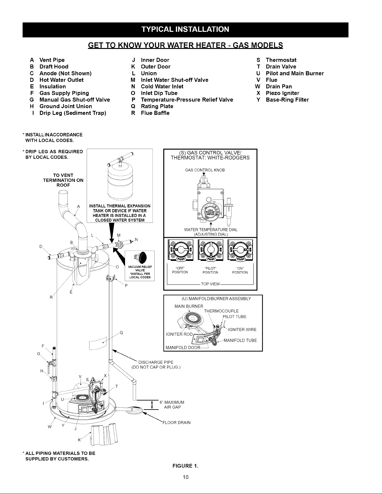
GET TO KNOW YOUR WATER HEATER - GAS MODELS
A Vent Pipe J Inner Door S Thermostat
B Draft Hood K Outer Door T Drain Valve
C Anode (Not Shown) L Union U Pilot and Main Burner
D Hot Water Outlet M Inlet Water Shut-off Valve V Flue
E Insulation N Cold Water Inlet W Drain Pan
F Gas Supply Piping O Inlet Dip Tube X Piezo Igniter
G Manual Gas Shut-off Valve P Temperature-Pressure Relief Valve Y Base-Ring Filter
H Ground Joint Union Q Rating Plate
I Drip Leg (Sediment Trap) R Flue Baffle
* INSTALL INACCORDANCE
WITH LOCAL CODES.
* DRIP LEG AS REQUIRED
BY LOCAL CODES.
TO VENT
TERMINATION ON
ROOF
D
F
G
H_
B
E
INSTALL THERMAL EXPANSION
TANK OR DEVICE IF WATER
HEATER IS INSTALLED IN A
CLOSED WATER SYSTEM
M
_\ p
V
VACUUM RELIEF
VALVE
*INSTALL PER
LOCAL CODES
NOT CAP OR PLUG.)
(S) GAS CONTROL VALVE/
THERMOSTAT: WHITE-RODGERS
GAS CONTROL KNOB
WATER TEMPERATURE DIAL
(ADJUSTING DIAL)
"OFF .... PILOT ON"
POSITION POSITION POSITION
TOP VIEW
(U) MANIFOLD/BURNER ASSEMBLY
MAIN BURNER
_i_.... THERMOCOUPLE
__ ",, pILOTTUBE
_x_o/__ :7_'_ IG N ITE R WIRE
IGNITER RO
,f- MANIFOLD TUBE
MANIFOLD DOOR _
PIPE
/
w
* ALL PIPING MATERIALS TO BE
SUPPLIED BY CUSTOMERS.
" 6" MAXIMUM
AIR GAP
FIGURE 1.
10
This gas water heater was manufactured to voluntary safety standards to reduce the likelihood of a flammable vapor ignition incident.
The new technology used in meeting these standards makes this product more sensitive to installation errors. Please review the
following checklist and make any required installation upgrades or changes.
Questions? Contact Sears at 1-800-4-MY-HOME (1-800-469-4663).
Installation Checklist
Water Heater Location
Water heater location is important and
performance. Please check the following:
[]
Installation area free of corrosive elements and flammable
materials.
[] Centrally located with the water piping system (For new
installations). Located as close to the gas piping and vent
pipe system as possible.
[] Located indoors and in a vertical position. Protected from
freezing temperatures.
[] Proper clearances from combustible surfaces
maintained and not installed directly on a carpeted floor.
[] Provisions made to protect the area from water damage.
Metal drain pan installed and piped to an adequate drain.
[] Sufficient room to service the water heater. See Clearances
and Accessibility section of this manual.
[] Water heater not located near an air moving device.
[] Is the installed environment dirty (excessive amounts of
lint, dirt, dust, etc.)? If so, the base-ring filter located on
the bottom of the water heater will need to be cleaned
periodically. Refer to the "Maintenance of your Water
Heater" section of this manual for information on cleaning
the base-ring filter.
Combustion Air Supply and Ventilation
Check for sufficient combustion air supply. Insufficient air for
the combustion of gas wilt result in the flame becoming "lazy",
thereby allowing heat to build up in the combustion chamber.
This excessive heat wilt cause a thermal switch on the door
assembly to trip. Isthe water heater installed in a closet or other
small, enclosed space? If so:
[]
Are there openings for make-up air to enter and exit the
room/area?
[]
Are the openings of sufficient size? Remember, if there
are other gas-fired or air-consuming appliances in the
same room, you need more make-up air. Refer to the
"Installation Instructions" and "Combustion Air Supply and
Ventilation" sections for specific requirements.
[]
Make sure that fresh air is not taken from areas that contain
negative pressure producing devices such as exhaust fans,
dryers, fireplaces, etc.
[]
Is there a furnace/air handler in the same room space as
the water heater? If so, has a return air duct system been
attached that exits the room? If so, check for leaks on the
air duct system. If no air duct system is present, correct
immediately by contacting a local Heating, Ventilation, Air-
Conditioning & Refrigeration (HVAC-R) authorized service
provider.
[]
Use a fresh air supply that is free of corrosive elements and
flammable vapors.
can affect system
[]
Fresh air openings must be sized correctly with consideration
given to the blocking effect of louvers and grilles.
[]
Ductwork must be the same cross-sectional area as the
openings.
Vent Pipe System
Check for proper drafting at the water heater draft hood. Refer
to the "Checking the Draft" section of this manual for the test
procedure. If the procedure shows insufficient draft is present,
please check the following:
[]
Draft hood properly installed.
[]
Vent connectors securely fastened with screws and
supported properly to maintain six inch clearance.
[]
Vent connector made of approved material and sized
correctly.
[]
Vent pipe system installed according to all local and state
codes or, in the absence of local and state codes, the
"National Fuel Gas Code", ANSI Z223.1(NFPA 54)-current
edition.
[] Flue baffle properly positioned in the flue tube.
[] Check the vent system for restrictions/obstructions and
check the vent termination height. Refer to the "Combustion
Air Supply and Ventilation" section of this water heater
manual for specific requirements.
[] Recheck for sufficient combustion air supply.
Water System Piping
[] Temperature and pressure relief valve properly installed with
a discharge line run to an open drain and protected from
freezing.
[] All piping properly installed and free of leaks.
[] Heater completely filled with water.
[] Closed system pressure build-up devices installed.
[] Mixing valve (when applicable) installed per manufacturer's
instructions (See "Water Temperature Regulation" section).
Gas Supply and Piping
[] Gas type is the same as that listed on the water heater rating
plate.
[] Gas line equipped with shut-off valve, union, and drip leg.
[] Use pipe joint compound or teflon tape marked as being
resistant to the action of petroleum [Propane (L.R)] gases.
[]
Adequate pipe size and approved pipe material.
[]
An approved noncorrosive leak detection solution used
to check all connections and fittings for possible gas leaks.
Correct any leak found.
11
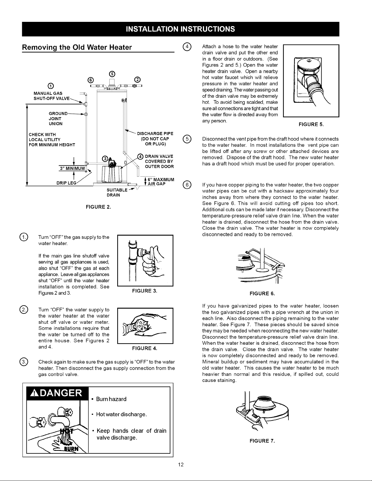
Removing the Old Water Heater (_
®
Q
MANUAL GAS
SHUT-OFF VALVE--_
GROUN D-------_
JOINT
UNION
CHECK WITH
LOCAL UTILITY
FOR MINIMUM HEIGHT
©
Turn "OFF" the gas supply to the
water heater.
3" MINIMUM
t
DRIP
FIGURE 2.
DISCHARGE PIPE
NOT CAP ('5.)(DO
OR PLUG)
DRAIN VALVE
COVERED BY
OUTER DOOR
6" MAXIMUM
AIR GAP
®
Attach a hose to the water heater
drain valve and put the other end
in a floor drain or outdoors. (See
Figures 2 and 5.) Open the water
heater drain valve. Open a nearby
hot water faucet which will relieve
pressure in the water heater and
speed draining. The water passing out
of the drain valve may be extremely
hot. To avoid being scalded, make
sure all connections are tight and that
the water flow is directed away from
any person.
Disconnect the vent pipe from the draft hood where it connects
to the water heater. In most installations the vent pipe can
be lifted off after any screw or other attached devices are
removed. Dispose of the draft hood. The new water heater
has a draft hood which must be used for proper operation.
If you have copper piping to the water heater, the two copper
water pipes can be cut with a hacksaw approximately four
inches away from where they connect to the water heater.
See Figure 6. This will avoid cutting off pipes too short.
Additional cuts can be made later if necessary. Disconnect the
temperature-pressure relief valve drain line. When the water
heater is drained, disconnect the hose from the drain valve.
Close the drain valve. The water heater is now completely
disconnected and ready to be removed.
FIGURE 5.
®
®
If the main gas line shutoff valve
serving all gas appliances is used,
also shut "OFF" the gas at each
appliance. Leave all gas appliances
shut "OFF" until the water heater
installation is completed. See
Figures 2 and 3.
Turn "OFF" the water supply to
the water heater at the water
shut off valve or water meter.
Some installations require that
the water be turned off to the
entire house. See Figures 2
and 4.
Check again to make sure the gas supply is "OFF" to the water
heater. Then disconnect the gas supply connection from the
gas control valve.
FIGURE 3.
FIGURE 4.
• Burn hazard
• Hotwater discharge.
• Keep hands clear of drain
valve discharge.
FIGURE 6.
If you have galvanized pipes to the water heater, loosen
the two galvanized pipes with a pipe wrench at the union in
each line. Also disconnect the piping remaining to the water
heater. See Figure 7. These pieces should be saved since
they may be needed when reconnecting the new water heater.
Disconnect the temperature-pressure relief valve drain line.
When the water heater is drained, disconnect the hose from
the drain valve. Close the drain valve. The water heater
is now completely disconnected and ready to be removed.
Mineral buildup or sediment may have accumulated in the
old water heater. This causes the water heater to be much
heavier than normal and this residue, if spilled out, could
cause staining.
FIGURE 7.
12
 Loading...