

_A/R8
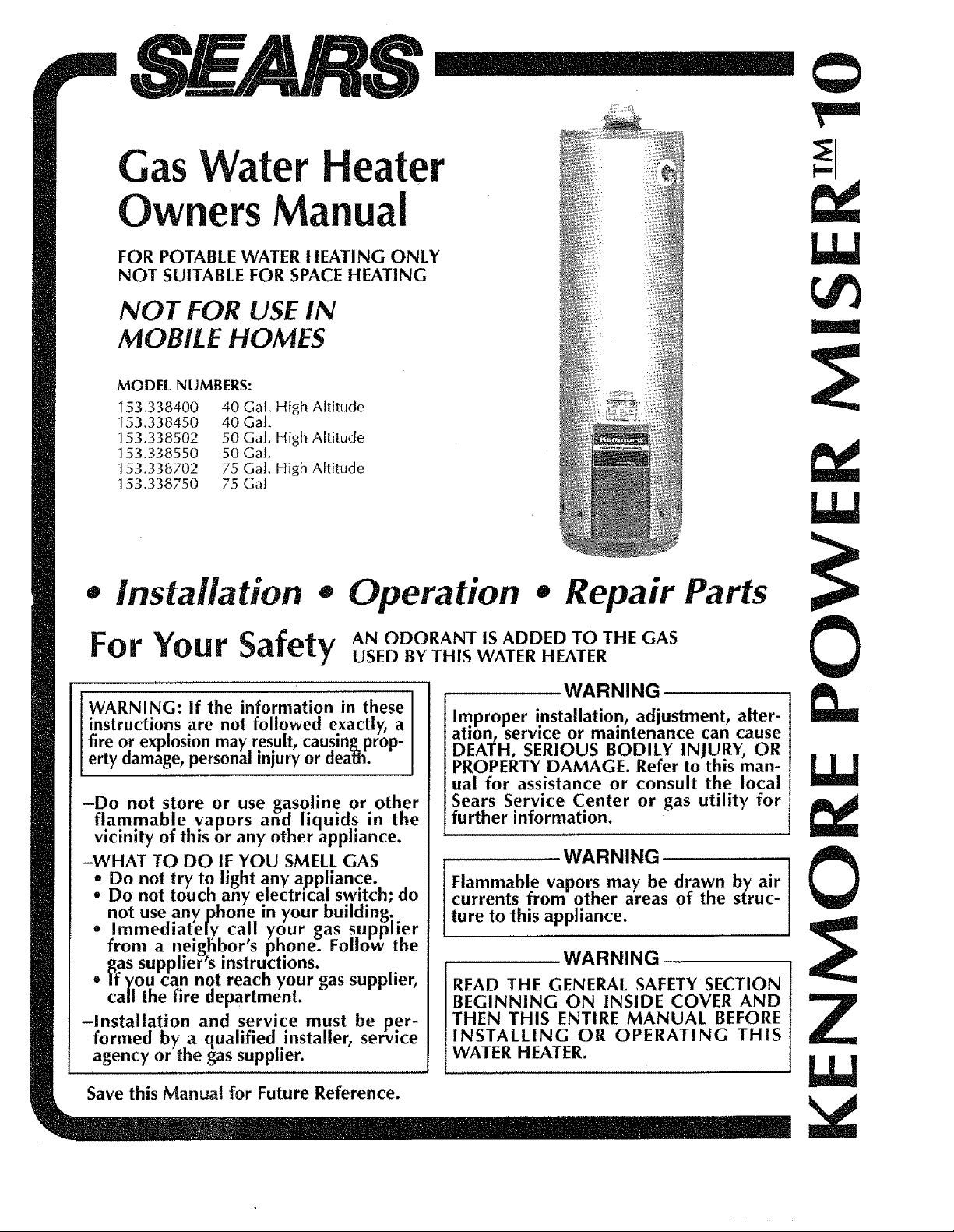
Gas Water Heater
Owners Manual
FOR POTABLE WATER HEATING ONLY
NOT SUITABLE FOR SPACE HEATING
NOT FOR USE IN
MOBILE HOMES
MODEL NUMBERS:
153.338400 40 Gal. High Altitude
153.338450 40 Gal.
153.338502 50 Gal. High Altitude
153.338550 50 Gal.
t 53.338702 75 Ga]. High Altitude
t 53.338750 75 Ga]
I
• installation • Operation • Repair Parts
For Your Safe USEDBYTH_SWATERHEATER
WARNING: If the information in these
instructions are not followed exactly, a
fire or explosion may result, causing prop-
erty damage, personal injury or dea_li.
-Do not store or use gasoline or other
flammable vapors and liquids in the
vicinity of this or any other appliance.
-WHAT TO DO IF YOU SMELL GAS
- Do not try to light any appliance.
. Do not touch any electrical switch; do
not use any phone in your building.
• Immediately call your gas supplier
from a neighbor's phone. Follow the
gas supplier's instructions.
- i'f you can not reach your gas supplier,
call the fire department.
-Installation and service must be per-
formed by a qualified installer, service
agency or the gas supplier.
ty AN ODORANT IS ADDED TO THE GAS
WARNING
Improper installation, adjustment, alter-
ation, service or maintenance can cause
DEATH, SERIOUS BODILY INJURY, OR
PROPERTY DAMAGE. Refer to this man-
ual for assistance or consult the local
Sears Service Center or gas utility for
! further information.
WARNING
Flammable vapors may be drawn by air
currents from other areas of the sTruc-
ture to this appliance.
WARNING
READ THE GENERAL SAFETY SECTION
BEGINNING ON INSIDE COVER AND
THEN THIS ENTIRE MANUAL BEFORE
INSTALLING OR OPERATING THIS
WATER HEATER.
10
Z
Save this Manual for Future Reference.
WARNING
Improper installation, adjustment, alteration, serviceor mainte-
nance can cause DEATH, SERIOUS BODILY INJURY, OR
PROPERTY DAMAGE. Refer to this manual for assistance or
consultyour local Sears Service Center for further information.
WARNING
At the time of manufacture this water heater was provided with
a combination temperature-pressure relief valve c:ertifled by a
nationally recognized testing laboratory that maintains periodic
inspection of production of listed equipment or materials, as
meeting the requirements for Relief Valves and Automatic Gas
ShutoffDevices for Hot Water Supply Systems, and the latest
edition of ANSI Z21.22 and the cove requirements of ASME. If
replaced, the valve must meet the requirements of local codes,
but not Jessthan a combination temperature and pressure reJief
valve certified as meeting the requirements for Relief Valves
and Automatic Gas Shutoff Devices for Hot Water Supply
Systems,ANSI Z21.22 by a nationaJly recognized testing labo-
ratory that maintains _eriodic inspection of production of listed
equipment or materials.
T_e valve must be marked with a maximum set pressurenot to
exceed the marked hydrostatic working pressure of the water
heater (150 Ibs./sq. in.) and a discharge capacity not less than
the water heater input rate as shown on the model ratin_
plate. (Electric heaters - watts divided by 1000 x 3415 equal
BTU/Hr. rate.)
Your local jurisdictional authority, while mandating the use of a
temperature-pressure relief valve complying with ANSI Z21.22
and ASME, may require a valve model different from the one
furnishedwith the water heater.
Compliance with such local requirements must be satisfied by
the installer or end user of the water heater with a locally pre-
scribedtemperature-pressure reJiefvalve installed in the desig-
nated opening in the water heater in place of the factory fur-
nishedvalve.
For safeoperation of the water heater, the relief valve must not
be removed from it's designatedopening or pJugged.
The temperature-pressure reJiefvalve mustbe i_n_stalleddirectly
into the fitting of the water heater designated for the relief
valve. Position the valve downward and provide tubing sothat
any discharge will exit only within 6 inches above, or at any
distance below the structural floor. Be certain that no contact
is made with any live eJectrica]part. The discharge opening
must not be blocked or reducedln size under any ctrcum-
stances.Excessive length, over 30 feet, or useof more than four
elbows can cause restriction and reduce the discharge capacity
of the valve.
No valve or other obstruction is to be placed between the
relief valve and the tank. Do not connect tubing directly to
dischargedrain unlessa 6_air gap is provided. To prevent bod-
ily injury, hazard to life, or property damage, the relief valve
must be allowed to discharge water in quantities should clr-
cumstances demand. If the discharge pipe is not connected to
a drain or other suitable means, the water fJow may cause
property damage.
The Discharge Pipe:
--Must not be smaller in size than the outlet pipe size of the
valve, or have any reducing couplingsor other restrictions.
--Must not be plugged or blocked.
--Must be of material listed for hot water distribution.
--Must be installed so as to allow complete drainage of both
the temperature-pressure relief valve, and the discharge
pipe.
--Must terminate at an adequate drain.
--Must not have any valve between the relief valve andtank.
WARNING
WATER HEATERSEQUIPPED FOR ONE TYPE GAS ONLY: This
water heater is equippedfor one type gasonly. Check the model
rating plate near the gas control valve for the correct gas. DO
NOT USETHIS WATER HEATERWITH ANY GAS OTHER THAN
THE ONE SHOWN ON THE MODEL RATING PLATE.Failure t_
use the correct gas can cause problems which can result in
DEATH, SERIOUS BODILY INJURY, OR PROPERTYDAMAGE. It
loOUhave any questions or doubts consult your gas supplier or
cal utility.
WARNING
Afire can start if combustiblematerialssuchas clothing,cleaning
materials, or flammable liquids are placed againstor next to the
water heater.
WARNING
INSTALLATIONS IN AREAS WHERE FLAMMABLE LIQUIDS
(VAPORS)ARE LIKELYTO BE PRESENTOR STORED (GARAGES,
STORAGE,AND UTILITY AREAS,ETC): Flammable liquids (such
as gasoline, solvents,propane (LP) or butane, etc.), all of which
emit flammablevapors, may be improperly storedor used in such
areas. The gaswater heater pilot fight or main burner can i_nite
suchvapors. The resultingflashback and fire can causedeath or
seriousburnsto anyonein the area, aswell asproperty damage.
If installation in such areas is your only option, then the
installation must be accomplished in a way that the pilot
flame and main burner flame are elevated from the floor at
least 18 inches. While this may reduce the changes of
flammable vapors from a floor spill being ignited, gasoline
and other flammable substances should never be stored or
used in the same room or area containing a gas water heater
or other open flame or sparkproducing appliance.
NOTE: Flammable vapors may be drawn by air currents from
otherareasof the structure to the appliance.
WARNING
HOTTERWATERCAN SCALD:Water heatersare intendedto pro-
duce hot water. Water heatedto a temperaturewhich will satisfy
clothes washing, dish washing, and other sanitizing needs can
scaldand permanently injure you upon contact. Somepeople are
more likely to be permanently injured by hot water than Others.
Theseinclude the elderly, children, the infirm, or physically/men-
tally, handicapl_ped.If anyone,usinghot.water coa_e_inour home fits
Into one of these groups or If there is a local or state law
requiring a certain temperature water at the hot water tap, then
you musttake special precautions. In addition to usingthelowest
possibletemperature settin_ that satisfiesyour hot w-aterneeds,
sometype of tempering device, suchas a mixingvalve, shouldbe
usedat the hot water tapsused by thesepeople or at the water
heater. Mixing valves are available at plumbing supply or hard-
ware stores.Follow manufacturers instructionsfor installation of
the valves.Before changingthe factory settingon the thermostat,
read the "Temperature Regulation"sectionin this manual.
WARNING
BEFORE LIGHTING [PROPANE (L.P.) GAS WATER HEATERS]:
Propane(L.P.)gasis heavierthan air. Shouldthere be a leak in the
system, the gas will settle near the ground. Basements, crawl
spaces,skirtedareasunder mobile homes(even when ventilated),
closetsand areasbelow groundlevel will serveas pocketsfor the
accumulationof this gas.Beforeattempting to light or relight the
water heater's pilot or turnin_ on a nearby electrical light switch,
be absolutelysLJrethere is no-accumulatedgasin the area. Search
for odor of gas by sniffingat _round level in the vicinity of the
appliance.If odor isdetected, follow stepsindicated at For Your
-- /t
Safety"on the coverpage of this manual then leavethe premises.
WARNING
Thiswaterheater must not be installed directly on carpeting.
Carpeting must be protected by a metal or wood panel heneat_h
the applianceextending beyond the full width anddepth of the
appliance by at least3 inches (76.2mm) in any direction, or if the
appliance isinstalled in an alcove or closet, the entire floor must
be coveredby the panel. Failureto heedthiswarning may resultin
afire hazard.
WARNING
A gas water heater cannot operate properly without the correct
amountof air for combustion.Do notinstall in a confinedarea such
as a closet,unlessyou provide air asshown in the "LocatingThe
New WaterHeater" section. Neverobstructthe flow of ventilation
air. If youhaveany doubtsor questionsat all, call your gascompa-
ny or SearsServiceCenter.Failureto provide the proper amount of
combustion air can result in a fire or explosion and can cause
DEATH,SERIOUSBODILY INJURY,OR PROPERTYDAMAGE.
WARNING
If this water heater will be used in beauty shops,barber shops,
cleaningestablishments,or self-service laundries with dry cleaning
equ]pmentrit is imperativethat the water heater or water heaters
be installed so that combustionand ventilationair be taken from
outsidetheseareas. Referto the "LocatingThe New Water Heater"
sectionof this manual and also the latest edition of the National
Fuel Gas Code, ANSI Z223.1, also referred to as NFPA 54 for
specificsprovided concerningair required.
WARNING
VENT DAMPERS- Any vent damper, whether it is operated ther-
mally or Otherwise must be removed if its use inhibits proper
_raftingof the water heater. - -
, hermally Operated Vent Dampers:Gas-fired water heaters hav-
ing thermal efficiency in excessof 80% may produce a relatlvelv
I .....
ow tlue gas temperature. Such temperatures may not be high
enoughto properly open thermally operated vent dampers. This
woulo causespillageof flue gasesandmay causecarbon monox-
idepoisoning.
Vent dampersmust bear evidenceof certification as complying
with the latest edition of American National Standard ANSI
Z21.68 (ANSI Z2t.66 & 67, respectively,cover electrlcal]y and
mechanically actuated vent dampers). Before installation of any
vent damper,consult your local SearsServiceCenter or the _as
utility forfurther information.
WARNING
1. The appliance and itsindividual,shutoffvalve must be discon-
nectedfrom the gas supplyp_pingsystemduring any pressure
testingof the gassystemat test pressuresin excessof Y_pound
per squareinch (3.SkPa).
2. The appliancemustbe isolatedfrom the gassupplypiping sys-
tem by closingits individual manual shutoff valve (luring any
pressuretestingof the gassupply pipingsystemat testpressures
equalor lessthan '/2poundpersquareihch (3.5kPa).
WARNING
Sootbuild-up indicatesa problemthat requirescorrection before
further use.Turn "OFF' gasto water heater and leave "OFF" until
repairsare made, becausefailure to correctthe causeof the soot-
mg can result in a fire or explosion causingDEATH, SERIOUS
BODILY INJURY,OR PROPERTYDAMAGE.
WARNING
The water heater with draft hood installedmustbe properlyvent-
_]to a chimne},which terminates outdoors. Never operate the
•vater Iteater unlessit isvented to the outdoorsand hasadequate
air supply, to avoid risks of improper operation, explosion or
asphyxlatmn.
WARNING
Obstructed or deteriorated vent systemsmay present a serious
health risk or asphyxiation.
WARNING
Chemical vapor corrosion of the flue and vent system may
occur if air for combustion contains certain chemical vapors.
Spray can propellants, cleaning solvents, refrigerator and air
conditioner refrigerants, swimming pooJ chemicals, calcium
and sodium chloride, waxes, bleach, and process chemicals
are typical compoundswhich are potentially corrosive.
WARNING
Minimum clearancesbetween thewater heater and combustible
constructionare 1'*at the sidesand rear, 4" at the front, and 6'*
from the vent pipe. Clearance from the top of the jacket is 18"
on most models. Note that a lesser dlmension may be allowed on
some models. Refer to the label on the water Eeater attached
adjacentto the gascontrol valve for all clearances.
WARNING
HYDROGEN GAS: Hydrogen gas can be produced in a hot
water system that has not been used for a long period of time
(generally two weeks or more). Hydrogen gas is extremely
flammable and explosive. To prevent the possibility of injury
under these conditions, we recommend the hot water faucet
be opened for several minutes at the kitchen sink before any
electrical appliances which are connected to the hot water
systemare used (such as a dishwasher or washing machine). If
hydrogen gas is present, there will probably be an unusual
soundsimilar to air escaping through the pipe asthe hot water
faucet is opened. There must be no smoking or open flame
near the faucet at the time it is open.
WARNING
INSULATING JACKETS: When installing an external water
heater insulation jacket on agaswater heater:
a. DO NOT cover the temperature-pressure relief valve.
b. DO NOT put insulation over any part of the top of the gas
water heater.
c. DO NOT put insulation over the gas control valve or gas
control valve/burner cover,or any accessareasto the burner.
d. DO NOT let insulation around the gas water heater to gel
within 8 inches of the floor {air must get to the burner).
e. DO NOT cover or remove operatin_ instructions, and safe-
ty related warning labels andmalenals affixed to the water
heater.
Failure to heed this will result in the possibility of a fire or
explosion.
WARNING
Do not usethis appliance if any part of it hasbeen under water.
Immediately call a Sears ServiceTechnician to inspectthe appli-
ance and to replace the gascontrol or any part of the burnersys-
tem which hasbeen under water.
CAUTION
WATER HEATERSEVENTUALLY LEAK:Installation of the water
heater mustbe accomplishedin sucha manner that if the tank or
any connections should leak, the flow of water will not cause
damage to the structure. When suchlocations cannot be avoid-
ed, a suitable drain pan should be installed under the water
heater. Drain pans are available at your local Searsstore. Such a
drainpan must benot greater than 1V2inches deep, havea mini-
mum length and width of at least 2 inchesgreater than the water
heater dimensionsand must bepiped to an adequate drain. The
pan must not restrict combustJ_onair flow. Under no circum-
stancesis the manufacturer or Sears to be held liable for any
water damage in connection with this water heater.
General Safety..................................................................................................................................2,3
Tableof Contents............................................................................................................................4
Introduction .........................................................................._..................................................................s
Specifications ........................................................................................................................................s
Preparing for the New Installation .........................................................................
Materials and Basic Tools Needed .....................................................i....................6
Materials Needed .................................................................................................................................................. 6
Basic Tools ............................................................................................................................................................ 6
Removing the Old Water Heater ..............................................................................z
Locating the New Water Heater. ...............:.............................................................a,9
Facts to Congider About Location .......................................................................................................................... 8
Combustion Air and Ventilation for Appliances Located in Unconfined Spaces ..................................................... 9
Combustion Air and Ventilation for Appliances Located in Confined Spaces ......................................................... 9
Installing the New Water Heater ......................................................................10-t4
Water Piping ........................................................................................................................................................ 10
Temperature-Pressure Re[ief Valve ....................................................................................................................... 11
Filling the Water Heater ....................................................................................................................................... 12
Venting ................................................................................................................................................................ 12
Gas Piping ........................................................................................................................................................... 13
_nstallation Checklist ........................................................................................................................................... 14
Lighting ...................................................................................................................................................1s,16
Temperature Regulation ......................................................................................................17
For Your
Start Up Conditions ............................................................................................................................................. 18
Condensation .................................................................................................................................................... 18
Smoke/Odor ...................................................................................................................................................... 18
Thermal Expansion ............................................................................................................................................ 18
Strange Sounds.................................................................................................................................................. 18
Operational Conditions .................................................................................................................................. 18,19
Smelly Water................................................................................................................................................ 18,19
"Air" in Hot Water Faucets................................................................................................................................. 19
High Temperature Shut Off System.................................................................................................................... t9
Not Enough or No Hot Water ............................................................................................................................ 19
Water Is Too Hot................................................................................................................................................ 19
Information .........................................................................................................._8,_9
Periodic Maintenance ........................................................................................................2o,21
Venting System Inspection ................................................................................................................................... 20
Burner Inspection ................................................................................................................................................ 20
Burner Cleaning .................................................................................................................................................. 20
Housekeeping ..................................................................................................................................................... 20
Temperature-Pressure Relief Valve Operation ...................................................................................................... 21
Tank Sediment Cleaning ...................................................................................................................................... 21
Draining .............................................................................................................................................................. 21
Drain Valve Washer Replacement ....................................................................................................................... 21
Service ................................................................................................................................................................ 21
Leakage Checkpoints ................................................................................................................22
" __epanrParts ......................................................................................................................................26,27
g,l l _
warranty ...................................................................................................................................................28
About Your Warranty ............................................................................. :............................................................. 28
SearsInstallation Policy ....................................................................................................................................... 28
SearsInstallation Warranty .................................................................................................................................. 28

Thank You forpurchasingaSearswaterheater.
Properly installed and maintained, it should give you
years of trouble free service. If you should decide that you
want the new water heater professionally installed by
Sears contact the local Sears Service Center or any Sears
store. They will arrange for prompt, quality installation by
Sears authorized contractors.
Abbreviations Found In This Instruction Manual
A.G.A. - American Gas Association
A.N.S.I. - American National Standards Institute
N.F.P.A. - National Fire Protection Association
WARNING
This gas-fired water heater is design certified by the
American Gas Association Laboratories under
American National Standards for Gas Water Heaters.
The installation must conform with this manual, Local
Codes and with the latest edition of the National Fuel
Gas Code, ANSI Z223.1.
This publication is available from your local govern_
ment or public library, gas company, or by writing
NEPA, Batterymarch Park, Quincy, MA 02269.
MODEL
NUMBER
153,338400
I53.338450
153.338502
153.338550
153.338702
153.338750
TANK
CAPACITY
IN GALLONS
40
40
50
50
75
75
TYPE
OF
GAS
NATURAL
NATURAL
NATURAL
NATURAL
NATURAL
NATURAL
B.T.U.
RATE
40,000
40,000
40,000
40,000
55,000
55,000
1. Read the "General Safety" section, pages 2 and 3 of 3.
this manual first and then the entire manual carefully.
If you don't follow the safety rules, the water heater
will not operate properly. It could cause DEATH, SERI-
OUS BODILY INJURYAND/OR PROPERTYDAMAGE. 4_
This manual contains instructions for the installation,
operation, and maintenance of the gas-fired water
heater. It also contains warnings through out the man-
ual that you must read and be aware of. All warnings
and all instructions are essential to the proper opera-
tion of the water heater and your safety. Since we can-
not put everything on the first few pages, READ THE
ENTIRE MANUAL BEFORE ATTEMPTING TO 5.
INSTALL OR OPERATETHE WATER HEATER.
2. The installation must conform with the instructions in
this manual; gas company rules; and Local Codes, or
in the absence of Local Codes, with the latest edition
of the National Fuel Gas code, ANSI Z223.1, also
referred to as NFPA 54_ This publication is available
from your local government or public iibrary or gas
company or by writing NFPA, Batterymarch Park,
Quincy, MA 02269.
RECOVERY RATE
GALS. PER
HOUR
46.0
46.0
46.0
46.0
59.2
59.2
If after reading this manual you have any questions or
do not understand any portion of the instructions, call
the Sears Service Center.
Carefully plan the place where you are going to put the
water heater. Correct combustion, vent action, and vent
pipe installation are very important in preventing death
from possible carbon monoxide poisoning and fires.
Examine the location to ensure the water heater com-
plies with the "Locating the New Water Heater" sec-
tion in this manual,
For California installation this water heater must be
braced, anchored, or strapped to avoid falling or mov-
ing during an earthquake. See instructions for correct
installation procedures. Instructions may be obtained
from your local dealer, wholesaler, public utilities or
California Office of the State Architect, 400 P Street,
Sacramento, CA 95814.
MINIMUM
VENT
PIPE
3" or 4"
3" or 4"
3" or 4"
3" or 4"
DIMENSIONS IN INCHES
HEIGHT TO
DIAMETER IACKET TOP
18" 60"
18" 60"
20" 59V/'
20" 59%"
4"
4"
24" 60"
24" 60"
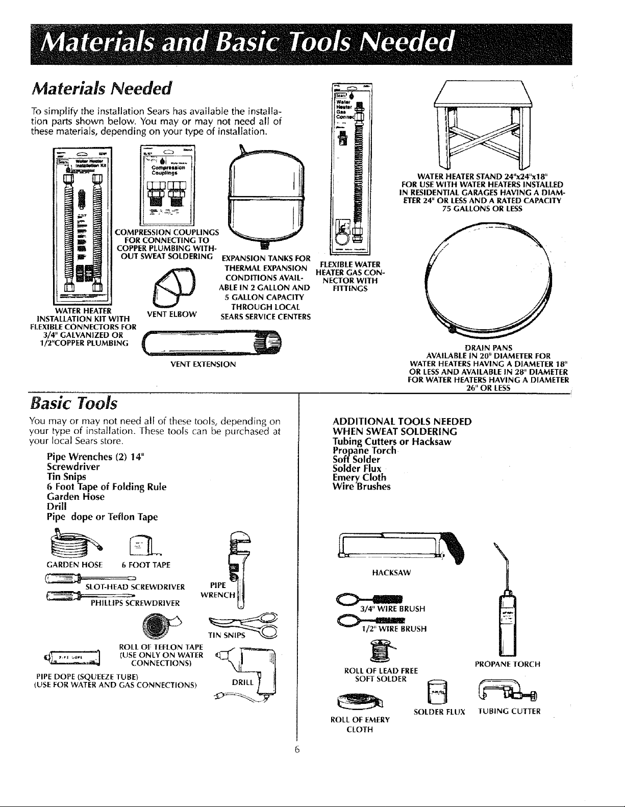
Materials Needed
To simplify the installation Sears hasavailabJe the installa-
tion parts shown below. You may or may not need all of
these materials, depending on your type of installation.
wmler
__mw_ef
CoupEtn_s
COMPRESSION COUPLINGS
FOR CONNECTING TO
COPPER PLUMBING WITH-
OUT SWEAT SOLDERING EXPANSION TANKS FOR
CONDITIONS AVAIL-
ABLE IN 2 GALLON AND
5 GALLON CAPACITY
THROUGH LOCAL
WATER HEATER
INSTALLATION KIT WITH
FLEXIBLE CONNECTORS FOR
3/4" GALVANIZED OR
1/2_COPPER PLUMBING
O THERMAL EXPANSION
VENT ELBOW SEARS SERVICE CENTERS
VENT EXTENSION
Basic Tools
You may or may not need all of these tools, depending on
your type of installation. These tools can be purchased at
your local Sears store.
Pipe Wrenches (2) 14"
Screwdriver
Tin Snips
6 Foot Tape of Folding Rule
Garden Hose
Drill
Pipe dope or Teflon Tape
i
J
FLEXIBLE WATER
HEATER GAS CON-
NECTOR WITH
WATER HEATER STAND 24"x24_x18 _'
FOR USE WITH WATER HEATERS INSTALLED
IN RESIDENTIAL GARAGES HAVING A DIAM-
FITTINGS
ETER 24" OR LESS AND A RATED CAPACITY
WATER HEATERS HAVING A DIAMETER 18"
OR LESS AND AVAILABLE IN 28" DIAMETER
FOR WATER HEATERS HAVING A DIAMETER
75 GALLONS OR LESS
AVAILABLE IN 20 _ DIAMETER FOR
ADDITIONAL TOOLS NEEDED
WHEN SWEAT SOLDERING
Tubing Cutters or Hacksaw
Propane Torch
Soff Solder
Solder Flux
Emery_Cloth
Wire Brushes
DRAIN PANS
26 _'OR LESS
GARDEN HOSE 6 FOOT TAPE
SLOT-HEAD SCREWDRIVER PIPE
PHILLIPS SCREWDRIVER
PIPE DOPE (SQUEEZE TUBE)
(USE FOR WATER AND GAS CONNECTIONS)
_ WRENCH
ROLL OF TEFLON TAPE
(USE ONLY ON WATER
CONNECTIONS)
HACKSAW
3/4 _ WIRE BRUSH
_RUSH
ROLL OF LEAD FREE
SOFT SOLDER
ROLL OF EMERY
CLOTH
PROPANE TORCH
SOLDER FLUX TUBING CUTTER

/tOF FPZ the
Turn gas supply to the water heater.
' WARNING
ing all gas appliances is used, also shut
"OFF" the gas at each appliance. Leave
all gas appliances shut "OFF" until the
If the main gas line shutoff valve serv- !
water heater installation is completed.
Turn "OFF" the water supply to the
water heater at the water shut off
valve or water meter. Some installa-
tions require that the water be
turned off to the entire house.
I
I
®
Q Disconnect vent pipe from the draft hood
where they connect to the water heater. In most
installations the vent pipe can be lifted off after
any screw or other attached devices are removed.
Dispose of the draft hood. The new water heater
has the draft hood which must be used for proper
operation.
Q a. lf you have copper piping to the
Q Disconnect the temperature-pres-sure relief valve drain fine. When
®
the
water heater, the two copper water
pipes can be cut with a hacksaw
approximately four inches away
from where they connect to the
water heater. This will avoid cutting
off the pipes too short. Additional
cuts can be made later if necessary.
the water heater is drained, discon-
nect the hose from the drain valve.
Close the drain valve. The water
heater is now completely discon-
nected and ready to be removed.
Check again to make sure the gas
®
supply is "OFF" to the water heater,
Then disconnect the gas supply con-
nection from the gas control valve.
Attach a to water heater
drain valve and put the other end in
a floor drain or outdoors. Open the
water heater drain valve, Open a
nearby hot water faucet which will
relieve pressure in the water heater
and speed draining,
The water passing out of the drain valve may be
extremely hot. To avoid being scalded, make
sure all connections are tight and that the water
flow is directed away from any person.
hose the
WARNING
b. If you have galvanized pipe to the
®
Mineral buildup or sediment may have accumulated
in the old water heater. This causes the water heater
to be much heavier than normal and this residue, if
spilled out, could cause staining.
water heater, loosen the two galva-
nized pipes with a pipe wrench at
the union in each line. Also dis-
connect the piping remaining to
the water heater. These pieces
should be saved since they may be
needed when reconnecting the
new water heater. Disconnect the
temperature-pressure relief valve
drain line. When the water heater
is drained, disconnect the hose
from the drain valve. Close the
drain valve. The water heater is
now completely disconnected and
ready to be removed.
CAUTION
Facts to Consider About the
Location
You should carefully choose an indoor location for the
new water heater, because the placement is a very impor-
tant consideration for the safety of the occupants in the
building and for the most economical use of the appli-
ance. This water heater is not for use in mobile homesor
outdoor installation.
Whether replacing an old water heater or putting the
water heater in a new location, the following critical
points must be observed.
1. The location selected should be indoors as close as
practical to the gas vent or chimney to which the
water heater vent is going to be connected, and as
centralized with the water piping system as possible.
The water heater, as all water heaters, will eventually
leak. Do not install without adequate drainage provi-
sions where water flow will cause damage.
CAUTION
WATER HEATERS EVENTUALLY LEAK: Installation of the
water heater must be accomplished in such a manner
that if the tank or any connecHons should leak, the flow
of water will not cause damage to the structure. When
such locations cannot be avoided, a suitable drain pan
should be installed under the water heater. Drain pans
are available at your local Sears store. Such a drain pan
must be no greater than 1% inches deep, have a mmP
mum length and width of at least 2 inclies greater than
the water heater dimensions and must be piped to an
adequate drain. The pan must not restrict combustion air
flow. Under no circumstances is the manufacturer or
Sears to be held liable for any water damage in connec-
tion with this water heater.
WARNING
INSTALLATIONS IN AREAS WHERE FLAMMABLE LIQUIDS
(VAPORS) ARE LIKELY TO BE PRESENT OR STORED
GARAGES, STORAGE AND UTILITY AREAS, ETC):
Flammable liquids (such as gasoline, solvents, propane (LP)
or butane, etc.) or other substances (such as adhesives,
etc.), all of which emit flammable vapors, may be improper-
ly stored or used in such areas. The gas water heater pilot
light or main burner can ignite such vapors. The resulting
flashback and fire can cause death or serious burns to any-
one in the area, as well as property damage.
If installation in such areas is your only option, then the
installation must be accomplished in a way that the pilot
flame and main burner flame are elevated from the floor at
least 18 inches. While this may reduce the changes of
flammable vapors from a floor spill being ignited, gasoline
and other flammable substances should never be stored or
used in the same room or area containing a gas water
heater or other open flame or spark producing appliance.
Also, the water heater must be located and/or protected so
it is not subject to physical damage by a moving vehicle.
NOTE: Flammable vapors maybe drawn by air currents
from other areas of the structure to the appliance.
WARNING
Propellants of aerosol sprays and volatile compounds,
(cleaners, chlorine based chemicals, refrigerants, etc.) in
addition to being highly flammable in many cases, will
also change to corrosive hydrochloric acid when exposed
to the combustion products of the water heater. The
results can be hazardous, and also cause product failure.
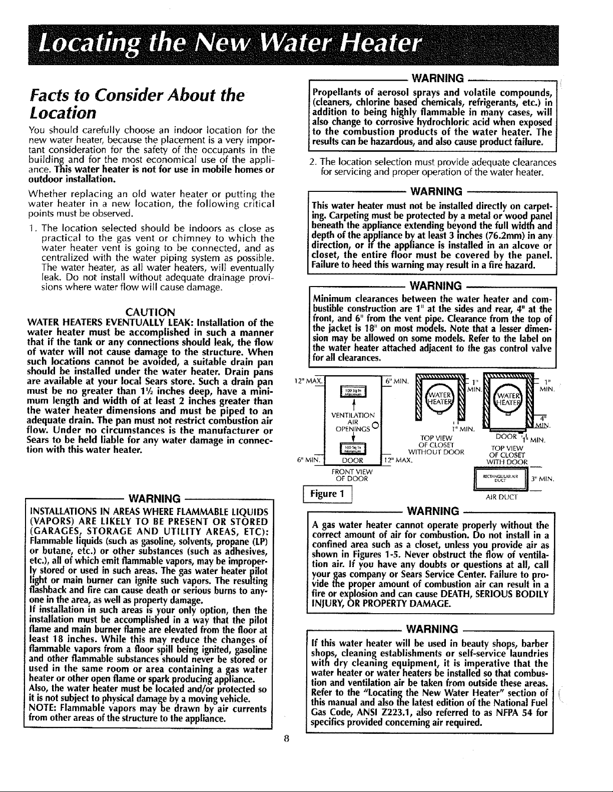
2. The location selection must provide adequate clearances
for servicing and proper operation of the water heater.
WARNING
This water heater must not be installed directly on carpet-
ing. Carpeting must he protected by a metal or wood panel
beneath the appliance extending be}_ondthe full width and
depth of the appliance by at least 3 inches (76.2mm) in any
direction, or if the appliance is installed in an alcove or
closet, the entire floor must be covered by the panel.
Failure to heed this warning may result in a fire hazard.
WARNING
Minimum clearances between the water heater and com-
bustible construction are 1" at the sides and rear, 4" at the
front, and 6" from the vent pipe. Clearance from the top of
the jacket is 18" on most models. Note that a lesser dimen-
sion may be allowed on some models. Refer to the label on
the water heater attached adjacent to the gas control valve
for all clearances.
12" MAX,
6" MI_-'.
[
Figure 1 ]
VENTILATION
AIR
OPENINGS O
DOOR
FRONT VIEW
OF DOOR
6'' MIN.
i
! 2" MAX,
l " MIN.
TOP VIEW
OF CLOSET
WITHOUT DOOR
ii
DOOR i
TOP VIEW
OF CLOSET
WITH DOOR
.... _._ 13. MI N
AIR DUCT
WARNING
A gas water heater cannot operate properly without the
correct amount of air for combustion. Do not install in a
confined area such as a closet, unless you provide air as
shown in Figures 1-5. Never obstruct the flow of ventila-
tion air. If you have any doubts or questions at all, call
your gas company or Sears Service Center. Failure to pro-
vide the proper amount of combustion air can result ,'n a
fle or explosion and can cause DEATH, SERIOUS BODILY
INJURY, OR PROPERTY DAMAGE.
WARNING
If this water heater will be used in beauty shops, barber
shops, cleaning establishments or self-service laundries
with dry cleaning equipment, it is imperative that the
water heater or water heaters be installed so that combus-
tion and ventilation air be taken from outside these areas.
Refer to the "Locating the New Water Heater" section of
this manual and also the latest edition of the National Fuel
Gas Code, ANSI Z223.1, also referred to as NFPA 54 for
specifics provided concerning air required.
I
" MIN.
0
_'ombustion Air and Ventilation
for Appliances Located in
Unconfined Spaces
Unconfined Space is a space whose volume is not lessthan 50
cubic feet per 1,000 Btu per hour of the aggregate input rating
of all appliances installed in that space. Rooms communicating
directly with the space in which the appliances are installed,
through openings not furnished with doors, are considered a
part of the unconfined space
fn unconfined spaces in buildings, infiltration may be adequate
to provide air for combustion, ventilation and dilution of flue
gases. However, in buildings of tight construction (for example,
weather stripping, heavily insulated, caulked, vapor barrier,
etc.), additional air may need to be provided using the methods
described in Combustion Air and Ventilation for Appliances
Located in Confined Spaces.
Combustion Air and Ventilation
for Appliances Located in
Confined Spaces
Confined Space is a space whose volume is less than 50 cubic
feet per 1,000 Btu per hour of the aggregate input rating of all
appliances installed in that space.
a, ALL AIR FROM INSIDE BUILDINGS:
(See Page 8 Figure 1, and Figure 2 below)
The confined space shall be provided with two permanent
openings communicating directly with an additional room(s)
of sufficient volume so that the combined volume of all
spaces meets the criteria for an unconfined space. The total
input of all gas utilization equipment installed in the com-
bined space shall be considered in making this determina-
tion. Each opening shall have a minimum free area of one
square inch per 1,000 BTU per hour of the total input rating
of all gas utilization equipment in the confined space, but
not less than 100 square inches. One opening shal] com-
mence within 12 inches of the top and one commencing
within 12 inches of the bottom of the enclosure.
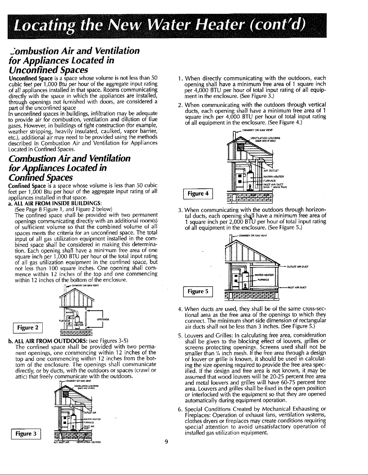
1. When directly communicating with the outdoors, each
opening shall have a minimum free area of 1 square inch
per 4,000 BTU per hour of total input rating of all equip-
ment in the enclosure. (See Figure 3.)
2. When communicating with the outdoors through vertical
ducts, each opening sha[t have a minimum free area of 1
square inch per 4,000 BTU per hour of total input rating
of all equipment in the enclosure. (SeeFigure 4.)
Q_IIdNEY I:>FtGAS VENT
Figure 4 ]
3. When communicating with the outdoors through horizon-
tal ducts, eachopening sh_.llhave a minimum free area of
1 square inch per 2,000 BTU per hour of total inputrating
of all equipment in the enclosure. (SeeFigure5.)
h-n
[ ]
b. ALL AIR FROM OUTDOORS: (see Figures 3-5)
The confined space shall be provided with two perma-
nent openings, one commencing within 12 inches of the
top and one commencing within 12 inches from the bot-
tom of the enclosure. The openings shall communicate
directly, or by ducts, with the outdoors or spaces (crawl or
attic) that freely communicate with the outdoors.
Figure5 I
4. When ducts are used, they shall be of the same cross-sec-
tional area as the free area of the openings to which they
connect. The minimum short side dimension of rectangular
air ducts shall not be less than 3 inches. (See Figure 5.)
5. Louvers and Grilles: In calculating free area, consideration
shall be given to the blocking effect of louvers, grilles or
screens protecting openings. Screens used shall not be
smaller than '/4 inch mesh. If the free area through a design
of louver or grille is known, it should be used in calculat-
ing the size opening required to provide the free area spec-
ified. If the design and free area is not known, it may be
assumed that wood louvers will be 20-25 percent free area
and metal louvers and griIIes will have 60-75 percent free
area. Louvers and grilles shall be fixed in the open position
or interlocked with the equipment so that they are opened
automatically during equipment operation.
6. Special Conditions Created by Mechanical Exhausting or
Fireplaces: Operation of exhaust fans, ventilation systems,
clothes dryers or firepJaces may create conditions requiring
special attention to avoid unsatisfactory operation of
installed gas uti]ization equipment.

Water Piping
WARNING
HOTTER WATER CAN SCALD:Water heaters are intended to
produce hot water. Water heated to a temperature which will
satisfy clothes washingt dish washing, and other sanitizing
needs can scald and permanently injure you upon contact.
Some _ople are more tikely to be permanently injured by hot
water than others. These include the elderly: children, the
infirm, or physlcally/mentaily handicapped. If anyone using
hot water in your home fits into one of t]_se groupsor if there
ISa local code or state law requiring a certain temperature
water at the.hot water tap, then you must take special precau-
tlons. In addition to using the lowest possibletemperature set-
ting that satisfiesyour hot water needs,some type of temper-
ing device, such as a mixing valve, should be usedat the hot
water taps usedby these people or at the water heater.Mixing
valves are available at p|umblng supply or hardware stores.
Follow manufacturers instruct ons for nstal ation of the
valves. Before changingthe factory settingon the thermostat,
read the "Temperature Regulation'!sectlon in this manual.
This water heater shall not be connected to any heating
systems or component(s) usedwith a non-potable water
heating appliance,
If a water heater tsinstalled in a closedwater supply system;
such as one having a back-flow preventer, check valve,
water meter with a check valve, etc.., in the cold water sup-
ply; means shall be provided to control thermal expansion.
Contact the local utility or local Sears Service Center on
how to controt this stuat on
2. Look at the top cover of the water heater. The cold
water inlet is marked cold. Put two or three turns of
teflon tape around the threaded end of the threaded-
to-sweat coupling and around both ends of the _/4"
threaded heat trap nipple. Using flexib]e connectors,
connect the cold water pipe to the cold water inlet of
the water heater.
NOTE: Thiswater heater is insulatedto minimize heat
lossfrom the tank. Further reduction in heat losscan
be accomplished by insulating the hot water lines
from the water heater.
INSTALLATION COMPLETED USING
SEARS INSTALLATION KIT
HOT OUTLET
TO HOUSE
-ql---
FLEXIBLE WATER
CONNECTORS
KN
THREADEDTO
SWEATCOUPLING
THREADED TO
SWEATCOUPLING
COLD INLET
WATER LINE
NOTE: To protect against untimely corrosion of hot and
cold water f|ttings, ]t is strongly recommended that di-
electric unions or couplings fie installed on this water
heater when connected to copper pipe.
The illustration shows the attachment of the water piping
to the water heater. The water heater is equipped with 3/,
inch water connections.
NOTE: If using copl_er tubing, solder tubing to an
adapter before attaching the adaptor to the cola water
inlet connection. Do not solder the cold water supply
llne directly to the cold water inlet. It will harm the dip
tube and damage the tank.
1. Look at the top cover of the water heater. The water
outlet is marked hot. Put two or three turns of teflon
tape around the threaded end of the threaded-to-sweat
coupling and around both ends of the 3/4"threaded heat
trap nipple with secondary anode. Using flexible con-
nectors, connect the hot water pipe to the ]4ot water
outlet on the water heater.
10
TEMPERATURE-
PRESSURE
RELIEF VALVE
DISCHARGE PIPE
(Do not cap or
plug)
t _ 6"AIRGAP
//
FLOOR DRAIN

"emperature-PressureRelief Valve
WARNING
At the time of manufacture this water beater was provided
with a combination temperature-pressure relief valve certi-
fied by a nationally recognlzedtesting laboratory that
maintains periodic inspection ofproductl-on of listed equip-
ment or materials, as meeting the requirements for Rell;ef
Valves and Automatic Gas Shutoff Devices for Hot Water
Supply Systems, and the latest edition of ANSI Z21.22 and
the code requirements of ASME. If replaced, the valve must
meet the requirements of local codes, but not less than a
combination temperature and pressure relief valve certified
as meeting the requirements for Relief Valves and
Automatic Gas Shutoff Devices for Hot Water Supply
Systems, ANSI Z21.22 by a nationally recognized testing
laboratory that maintains periodic inspection of production
of listed equipment or materials.
The valve must be marked with a maximum set pressure
not to exceed the marked hydrostatic working pressure of
the water heater (150 Ibs./sq. in.) and a discharge capacity
not less than the water heater input rate as shown on the
model rating plate. (Electric heaters - watts divided by
1000 x 3415 equal BTU/Hr. rate.) . .
Your local iurisd_ctlona! authority, while mandating the use
of a temperature-pressure relief valve complying with ANSi
Z21.22 and ASME, may require a valve model different
from the one furnished wlth the water heater.
Compliance with such local requirements must be satisfied
y the installer or end user of the water heater with a local-
_, prescribed temperature-pressure relief valve installed in
the designated opening in the water heater in place of the
factory furnished valve.
For safe operation of the water heater, the relief valve must
not be removed from it's designated opening or plugged.
The temperature-pressure relief valve must be installed
directly _'nto the f[ttlng of the water heater designated for
the relief valve. Position the valve downward and provide
tubing so that any. discharge will exit only within 6 inches
above, or at any distance below the structural floor. Be cer-
tain that no contact is made with any live electrical part.
The discharge opening must not be blocked or reduced in
size under any circumstances. Excessive length, over 30
feet, or use of more than four elbows can cause restriction
and reduce the discharge capacity of the valve.
No valve or other obstruction is to be placed between the
relief valve and the tank. Do not connect tubing directly to
discharge drain unless a 6 air gap is provided. To prevent
bodily m_niury,hazard to llfe, or property damage, the relief
valve must be allowed to discharge water in quantities
should circumstances demand. If the discharge pipe is not
connected to a drain or other suitable means, the water
flow may cause property damage.
The Discharge Pipe:
--Must not be smaller in size than the outlet pipe size of
the valve, or have any reducing couplings or other
restrictions.
--Must not be plugged or blocked.
--Must be of materl'al listed for hot water distribution.
--Must be installed so as to allow complete drainage of
both the temperature-pressure relief valve, and the dis-
charge pipe.
--Must not have any valve between the relief valve and tank.
--Must terminate at an adequate drain.
WARNING
The temperature-pressure relief valve must be manually
operated at least once a year. Caution should be taken to
ensure that (1) no one is in front of or around the outlet of
the temperature-pressure relief valve discharge line, and (2)
the water manually discharged will not cause any bodily
injury or property damage because the water may be
extremely hot.
If after manually operating the valve, it fails to completely
reset and continues to release water, immediately close the
cold water inlet to the water heater, follow the draining
instructions, and replace the temperature-pressure relie_
valve with a new one.
HOT
-,fp----- t
SHUT OFF
VALVE
FLOOR DRAIN ]
RELIEF VALVE OPENING
AT THE TIME OF MANUFACTURE,THIS WATER HEATERWAS PROVIDED
WITH A COMBINATIONTEMPERATURE-PRESSURERELIEF VALVELISTED
AS COMPLYINGWITH THE STANDARDFOR RELIEF VALVESAND AUTO-
MATICGASSHUTOFF DEVICESFORHOTWATERSUPPLYSYSTEMS,ANSI
Z21.22. FOR SAFE OPERATION OF THE WATER HEATER, THE RELIEF
VALVE MUST NOT BE REMOVED FROM ITS DESIGNATED POINT OF
INSTALLATIONOR PLUGGED.
YOUR LOCALJURISDICTfONALAUTHORITy,WHILEMANDATINGTHEUSE
OF A TEMPERATURE-PRESSURERELIEF VALVECOMPLYINGWiTH ANSI
Z21.22AND ASME, MAYREQUIRE AVALVEMODELDIFFERENTFROMTHE
ONEFURNISHEDWITHTHEWATERHEATER.
COMPLIANCEWITH SUCH LOCAL REQUIREMENTSMUST BE SATISFIED
BY THE INSTALLER OR END USER OF THE WATER HEATER WITH A
LOCALLY PRESCRIBED TEMPERATURE-PRESSURE RELIEF VALVE
INSTALLED_NTHEDESIGNATEDOPENINGtN THE WATERHEATER.
SEE MANUAL HEADING--°TEMPERATURE-PRESSURE RELIEF VALVES"
FOR INSTALLATIONAND MAINTENANCEOF RELIEFVALVE,DISCHARGE
LINEAND OTHERSAFETYPRECAUTIONS.
11
COLD
TEMPERATURE-
PRESSURE
RELIEF VALVE
(Do not cap
or plug)

Filling the Water Heater
CAUTION
Never use this water heater unless it is completely filled
with water. To prevent damage to the tank, the tank must
be filled with water. Water must flow from the hot water
faucet before turning "ON" gas to the water heater.
To fill the water heater with water:
1. Close the water heater drain valve by turning the han-
dle to the right (clockwise). The drain valve is on the
lower front of the water heater.
2. Open the cold water supply valve to the water heater.
NOTE: The cold water supply valve must be left open
when the water heater is m use.
3. To insure complete filling of the tank, allow air to exit
by opening the nearest hot water faucet. Allow water
to run until a constant flow is obtained. This will let air
out of the water heater and the piping.
4. Check al! new water piping for leaks. Repair as needed.
Venting
WARNING
VENT DAMPERS - Any vent damper, whether it is ol_erated
thermally or otherwise must be removed if its use mhlbits
proper drafting of the water heater.
Thermally Operated Vent Dampers: Gas-fired water heaters
having thermal efficiency in excess of 80% may l)roduce a
relatively low flue gas temperature. Suchtempe'ratures may
not be high enough to properly open thermally operated
vent dampers. This would cause spillage of flue gases and
may cause carbon monoxide poisoning.
Vent dampers must bear evidence of-certification as com-
plying with the latest edition of the American National
Standard ANSI Z21.68 (ANSI Z21.66 & 67, respectively,
cover electrically and mechanically actuated vent dampers).
Before installation of any vent damper, consult the local
Sears Service Center or gas utility for further information.
1. Place the draft hood legs in the receiving holes on the_
top of the water heater. The legs will snap in the holL
to give a tight fit.
2. Place the vent pipe over the draft hood. With the vent
pipe in position, drill a small hole through both the
vent pipe and draft hood. Secure them together with a
sheet meta_ screw.
DRAFTHOOD _r [VENT.[ [ _,
_J L_VENTTO OUTDOORS
DRAFT H__ H|MNEY
i WARNING
The water heater with draft hood installed must be connect-
ed to a chimney which terminates to the outdoors. Never
operate the water heater unless it is vented to the outdoors
and hasadequate air supply to avoid risksof improper opera-
tion, explosion or asphyxiation.
WARNING
The vent pipe from the water heater must be no less than the|
diameter of the draft hood outlet on the water heater, and must
slopeupward to the chimney at leastY4inchper linearfoot.
All vent gases must be completely vented to the outdoor_
of the structure (dwelling). Install only the draft hood pr_
vided with the new water heater and no other draft hood.
Vent pipes must be secured at each joint with sheet metal
screws.
/
J
WARNING ......
TO insure proper venting of this gas-fired water heater, the
correct vent pipe diameter must be utilized. Any additions or
deletions of other gasappliances on a common vent with this
water heater may adversely affect the operation of the water
heater. Consult the local Sears Service(_enter or gasutility if
any such changesare planned.
For proper venting in certain installations, a larger diameter
vent pipe may be necessary. Due to great variances in
installations, unforeseeable by the manufacturer of the
water heater, you must consult your gas company to aid
you in determining the proper venting for your water heater
from the vent tables in the latestedition of the National Fuel
Gas Code ANSI Z223.1, also referredto asNFPA 54.
Check the venting system for signsof obstruction or deterio-
ration and replace if needed.
The combustion and ventilation air flow must not be
obstructed.
WARNING
Obstructed or deteriorated vent systemsmay present
serioushealth risk or asphyxiation.
VENT PIPEINSTALLATION
There must be a minimum of 6" clearance between single wall
vent pipe and any combustible material. Fill and seal any clear-
ance between single wall vent pipe and combustible material
with mortar mix, cement, or other noncombustible substance.
For other than single wail, follow vent pipe manufacturer's clear-
ance specifications. To insure atight fit of the vent pipe in a brick
chimney, seal around the vent pipe with mortar mix cement.
, WARNING
Failure to have required clearances between vent piping [
and combustible material will result in a fire hazard.
WARNING
j Besure vent pipe is properly connected to prevent esca e of
dangerousflue gases'which could causedeadly asphyxia_on.
'" WARNING
Chemical vapor corrosion of the flue and vent system ma
occur if air for combustion contains certain chemi_:alvapors."
Spray can propellants, cleaning solvents, refrigerator and air,
conditioner refrigerants, swimming pool chemicals, calcium I
and sodium chloride, waxes, bleacli and process chemicals I
are typical compoundswhich are potentially corrosive. [
12
Lv
I
I
I

pipi.g
WARNING
Make surethe gas suppliedis the sametype listed on the
model ratingplate.Theinlet gaspressuremustnotexceed14
incheswater column [1/5poundper squareinch (3.5kPa)].
The minimum inlet gaspressurelisted on the model rating
plateisforthe purposeofinput adjustment.
WARNING
if thegascontrolvalveissubjectedto pressuresexceedingY2/
poundpersquareinch (3.SkPa),thedamagetothe gascon-
trol valvecouldresultina fire or explosionfrom leak]nggas.
WARNING
/
Use pipejoint compoundor teflon tape marked as being|
resistantto the actionof petroleum[Propane(L.P.)]gases.
J
SEDIMENT TRAP
A sediment trap shall be installed as close to the inlet of
the water heater as practical at the time of water heater
/
installation. The sediment trap shall be either a tee fitting
with a capped nipple in the bottom outlet or other device
recognized as an effective sediment trap. If a tee fitting is
]
used, it shall be installed in conformance with one of the
methods of installation shown below.
WARNING
alsoturn "OFF"thegasateachappliance.Leaveall gasappli-
I If themain gaslineshutoffservingall gasappliancesis used,I
ancesshutoff untilthewaterheaterinstallationisComplete.
A gas line of sufficient size must be run to the water
heater. Consult the latest edition of National Fuel Gas
Code ANSI Z223.1, also referred to as NFPA54 and the
gas company concerning pipe size.
There must be:
-A readily accessible manual shut off valve in the gas sup-
ply line serving the water heater, and
-A drip leg (sediment trap) ahead of the gas control valve
to help prevent dirt and foreign materials from entering
the gascontrol valve.
-A flexible gas connector or a ground joint union between
the shutoffvalve and control valve to permit servicing of
the unit.
Be sure to check al] the gas piping for leaks before lighting
the water heater. Use a soapy water solution, not a match
or open flame. Rinse off soapy solution and wipe dry.
Standard Models are for installation up to 3,300 feet
above sea level.
High Altitude Models are for installation from 3,300 to
5,500 feet above sea level.
If a standard model is installed above 3,300 feet or a high
altitude model is installed above 5,500 feet, the input rat-
ing must be reduced at the rate of 4 percent for each
1,000 feet above sea level. Contact your local Sears
Service Center or gas utility for further information.
WARNING
The appliance and itsgas connection must be leak test-
ed before placing the appliance in operation.
WARNING
Theapplianceanditsindividualshutoffvalvemust be discon-
nectedfromthe gassupplypipingsystemduringan)'pressure
testingof that systemat testpressuresin excessof Y_pound
persquareinch(3.SkPa).
Theappliancemustbeisolatedfromthegassupplypipingsys-
tem I)yclosingits individualmanualshutoffValveduring any
pressuretestingof thegassuppl)'pipingsystemat testpres-
suresequalto orlessthan%poundpersquareinch(3.5kPa).
I
I
Connectingthe gaspiping to the gas control valve of the water
heatercan be accomplishedbyeitherof the two methodsshown.
GAS PIPING WITH FLEXIBLE CONNECTOR
_i_ GAS SUPPLY PIPING
MANUAl. !_
SHUTOFF ll_.-_
VALVE wr_ FLEXIBLEGAS CONNECTOR
=
GROUND JOINT LOOP
UNION (Optional)
6J_
LABELED AS COMPLYING
WITH ANSI.STANDARDS
CONTROL
GAS PIPING WITH ALL BLACKIRON PIPE
TO GAS CONTROL
GAS SUPPLY PIPING
MANUAL
SHUTOFF _[L_
VALVE _
-_ BLACK/PIPE
GROUND JOINT_:_ / ._
UNION _ I_ r_ GAS
--_,, _:_ D IRPLEG _ VALVE
_1_ CAP
_.__ CONTROL
WARNING
Contaminantsin thegaslinesmaycauseimproperoperation
of the gascontrolvalvethat may resultin fire or explosion.
Beforeattachingthe gaslinebesurethatall gaspipe]sclean
on the inside.Totrap any dirt or foreignmaterial in the gas
supplyline, a drip leg (sometimescageda sedimenttrap)
mustbe incorporatedin the piping. Thedrip leg mustbe
readily accessible. Install in accordance with the "Gas
Piping"section.Refer to the latestedition of the National
FuelGasCode,ANSIZ223.1, alsoreferredtoasNFPA54.
13
GAS
VALVE

IIIIH'IHI"I'I'IIII'lllll I I _ I I i
0
Installation Checklist
BEFORE LIGHTING THE PILOT:
1. Check the gas lines for leaks.
a. Use a soapy water solution. DO NOT test for gas
leaks using a match or open flame.
b. Brush the soapy water solution on all gas pipes,
joints and fittings.
c. Check for bubbling soap. This means you have a
leak. Turn "OFF" gas and make the necessary
repairs.
d. Recheck for leaks.
e. Rinse off soapy solution and wipe dry.
2. Is the new temperature-pressure relief valve properly
installed and piped to an adequate drain? See
"Temperature-Pressure Relief Valve" section.
3. Are the cold and hot water lines connected to the
water heater correctly? See "Water Piping" instruc-
tions in the "Installing the New Water Heater" section.
4. Is the water heater completely filled with water? See
"Filling the Water Heater" instructions in the
"Installing the New Water Heater" section.
5. Will a water leak damage anything? Seethe "Locating
the New Water Heater" section.
VENT PIPE TO
OUTDOORS
OR CHIMNEY
UNION SHUTOFF VALVE
6. Is there proper clearance between the water heater
and anything that might catch fire? Seethe "Locating
the New water Heater" section.
7. Do you have adequate ventilation so that the water
heater will operate properly? See "Combustion Air
and Ventilation" in the "Locating the New Water
Heater" section.
8. Is the draft hood vent piping properly secured? See
"Venting" instructions in the "lnsta]ling the New
Water Heater" section.
9. Is there proper clearance between the vent pipe and
anything that might catch on fire? See "Venting"
instructions in the "Installing the New Water Heater"
section.
10. Is the vent pipe properly sloped and does the vent
terminate outdoors? See "Venting" instructions in the
"Installing the New Water Heater" section.
11. Do you need to call your gas company to check the
gaspipe and its hookup?
I
DRIP
(SEDIMENT TRAP)
GAS SUPPLY
PIPECAP
• COLD
DRAFT
HOOD
RELIEFVALVE
MODEL RATING PLATE
DISCHARGE PiPE
Lpor plug)
DRAIN VALVE
under cover)
k
6 INCH AIR GAP
• FLOORDRAIN
14

WARNING
BEFORE LIGHTING [PROPANE (L.P.) GAS WATER
HEATERS]: Propane (L.P.) gas is heavier than air.
Shouldthere be a leak in the system,the gaswill settle
near theground. Basements, crawl spaces, skirted
areas under mobile homes (even when ventilated),
closets and areas below ground level will serve as
pockets for the accumulation of this gas. Before
attempting to light or relight the water beater's pilot or
turning on a nearby electrical light switch, be absolute-
ly surethere is no accumulated gasin the area. Search
for odor of gasby sniffingat ground level in the vicini-
ty of the appliance. If odor is detected, follow the steps
indicated at "For Your Safety" on the cover page of
this manual, then leave the premises.
Lighting and operating instructions are located on front of
the water heater, above or to one side of the gas control
valve.
WARNING
AN ODORANT IS ADDED TO THE GAS USED
BY THIS WATER HEATER.
FOR YOUR SAFETY
IF YOU SMELLGAS:
1. Do not try to light any ap.pliance.
2. Do not touch any,electNcal switch; do not use any
phone in your_budding.
3. Immediately call your gassupplier from a neighbor's
phone. Follow the gassupplier's instructions.
4. If you cannot reach your gassupplier, call the fire
department.
Figure 6 ]
I Figure 7 I
WARNING
DO NOT force the gas control knob. Use only your
hand to push it down to light the pilot, or to turn it to
"ON", "OFF" or "PILOT". Never use a tool such as a
lever,wrench or pliers. Do not hit or damage the knob.
A damaged knob may result in an explosion and seri-
ous injury. If you have problem turning the knob, call
the gassupplier immediately.
CHECK FOR LEAKS
Be sure to check all your gas pipes for leaks before light-
ing your water heater. Use a soapy water solution, not a
match or open f_ame. Check the factory gas fittings after
pilot is lit and gas control knob is still in "PILOT" position.
Then, check the fittings when the main burner is turned
"ON". Use asoapy water solution for this, too.
Figure8 ]
INNER DOOR
OUTER DOOR
Figure 9 ]
15

FOR YOUR SAFETY READ BEFORE LIGHTING
If you do not follow these instructions exactly, a fire or explosion
I WARNING I
may result causing property damage, personal injury or loss of life.
A.This appliancehasa pilotwhichmustbe lightedby
hand.Whenlightingthepilot,followtheseinstructions
exactly.
B.BEFORELIGHTINGsmellallaroundtheappliancearea
for gas. Be sureto smellnextto thefloor because
somegasisheavierthanairandwillsettleonthefloor.
WHATTODOIF YOUSMELLGAS
: Donottrytolightanyappliance.
Do not touch any electricswitch;do not useany
phonehiyourbuilding.
• Immediatelycallyourgassupplierfromaneighbor's
phone.Followthegassuppfier'sinstructions.
• If youcannotreachyourgas supplier,callthe fire
department.
C. Useonlyyourhandto push[nor turnthegas control
knob.Neverusetools,if the knobwillnotpushinor
turnby hand,don'ttryto repairit, calla qualifiedser-
vicetechnician.Forceor attemptedrepairmayresult
ina fireorexplosion.
D. Donot usethisapplianceif anypart hasbeenunder
water.Immediatelycall a qualifiedservicetechnician
toinspecttheapplianceandto replaceanypertofthe
controlsystemandany gascontrol whichhas been
underwater.
1.STOP!Readthesafetyinformationaboveonthislabel.
2.Removeouterdoor.
3. Setthe thermostatto lowest settingby turningthe
watertemperaturedialclockwise,(f_-'_) toitslowest
temperaturesetting(witharrowondial)asshown,DO
NOT FORCE.
4.Turngascontrolknobclockwise_ to"OFF posi-
tion.Knob cannotbeturnedfrom "PILOT"to "OFF"
unlessknobis depressedslightly.DO NOT FORCE.
(Figure6, page15)
5.Waitfive(5) minutesto clearoutanygas.Ifyou then
smellgas,STOP!Follow"B" in thesafetyinformation
aboveonthis label.If youdon't smellgas,go to the
nextstep.
6. Remove(or open)innerdoor locatedbelowthe gas
controlunit.(F,gure9,page15)
7.Findpilot-followmetaltubefromgascontrol.Thepilot
islocatedontheright handsideofthe burner.
PILOT BURNER /_ THERMOCOUPLE
6.Ifyoudon'tsmellgas,turnknobongascontrolcounter
clockwise_ to"PILOT"pesition.(Figure7, paga15).
LIGHTING iNSTRUCTIONS
9. Push in control knob all the way and hold down
Immediatelylightthe pilotwitha match.Continueto
hold controlknobin for aboutone (1) minuteafter
thepilotis lit. Releaseknoband itwiltpopback up.
Pilotshouldremainlit.if it goesout,repeatsteps4
throughg.
• if knobdoesnotpopupwhenreleased,stopand
immediatelycallyour servicetechnicianorgas
supplier.
, If the pilotwill not stay lit after several tries,
depressandturnthegascontrolknobclockwise
_)') to "OFF"andcallyourservicetechnWolan
orgassupplier.(Figure6, page15)
10.Replace(or close)innerdoor.Replaceouterdoor if
doordoesnotcovergascontrolon/offknobortem-
peratureadjustmentknob.(Figure9,page15)
11.At armslengthaway,turngascontrotknobcounter-
clockwise _O to the full "ON" position.
WARNING Donot use gas control knobto reg.
ulate gas flow, (Figure8, page15)
12.At arms length away,set thethermostatto desired
setting.Themark(T ) HOTindicativeofapproximate
120°Fis preferredstartingpoint. Somelocallaws
may requirea lowerstartingpoint.If hotterwateris
desired,seeinstruction manualand"warning"below.
13.Replacetheouterdoorifnotreplacedinstep10.
Hotterwaterincreasestheriskof scaldinjury. Beforechangingtemperaturesettingsee instructionmanual.
WARNING j
TO TURN OFF GAS TO APPLIANCE
1.Set thethermostatto lowestsetting byturningthe
watertemperaturedialclockwise(f"_,) toits lowest
temperaturesetting{witharrowondial)as shown.DO
NOT FORCE.
2.Turngascontrolknobclockwise_'J to"OFF"posi-
tion.Knobcannotbe turnedfrom"PILOT" to "OFF"
unlessknobisdepressedslightly.DO NOT FORCE,
(Figure6, page15)
3.Replaceouterdoor(if removed).
16

Due to the nature of the typical gas water heater, the
water temperature in certain situations may vary up to
30°F higher or lower at the point of use such as, bathtubs,
showers, sink, etc.
This means that when the temperature adjustment dial is
set at the mark approximating 120 F, the actual water
temperature at any hot water tap could be as high as
150°F or as low as90°F.
Any water heater's intended purpose is to heat water. Hot
water is needed for cleaning (bodies, dishes, clothing).
Hot water will present a scald hazard. Depending on the
time element, and the people involved (norma/adults,
children, toddlers, elderly, infirm, etc.) scalding may
occur at different temperatures.
WARNING
HOTTER WATER CAN SCALD: Water heaters are intended to
produce hot water. Water heated to a temperature which
will satisfy clothes washing, dishwashin[[, and other sanitiz-
ing needs can scald and permanently injure you upon con-
tact. Some people are more likely tobe permanently injured
by hot water than others. These includethe elderly, _:hildren,
the infirm, or physically/mentally handicapped. If anyone
using hot water in your home fits into one of |hese _[roups or
if there is a local code or state law requiring a certain"tem-
perature water at the hot water tap, then you must take spe-
cial precautions. In addition to using the lowest possibletem-
perature setting that satisfies your hot water needs, some
type of tempering device, such as a mixing valve, should be
used at the hot water taps used b_.these people or at the
water heater. Mixing valvesare ava,lable at plumbin[_supply
or hardware stores. Follow manufacturers instruct|ons for
installation of the valves. Before changingthe factory setting
on the thermostat, read the "Temperature Regulation" sec-
tion in this manual.
WARNING
Never allow small children to use a hot water tap, or to i
draw their own bath water. Never leave a child or hand-
icapped person unattended in a bathtub or shower
/
J
Turn the water temperature dial clockwise (_'_) to
decrease the temperature, or counterclockwise (_-"_)
to increase the temperature.
V HOT-Is a thermostat setting of approximately
120°F, which will supply hot water at the
most economical temperatures. The temper-
ature adjustment knob can be turned lower
than "HOT" if desired.
A-Is a thermostat setting of approximately
130°F.
B-Is a thermostat setting of approximately
140°F. This is the lowest setting for supply of
hot water to dishwashers.
C-Is a thermostat setting of approximately
150°F.
VERY HOT-Is a thermostat setting of 160°F. It is recom-
mended that the dial be set lower whenever
possible.
NOTE: Residential gas-fired water heaters will not supply
sanitizing hot water for dishwashers.
The thermostat of this water heater has been factory set at
its lowest position, to reduce the risk of scald injury. ]t is
adjustable and must be reset to the desired temperature
setting. The mark (V) HOT indicative of approximately
120°F is the preferred starting point. Some states have a
requirement for a lower setting. If you need hotter water,
follow directions for temperature adjustment, but beware
of the warnings in this section.
WARNING
shut off, turn "OFF _' the manual gas control valve to
Should overheating occur or the gas supply fail to I
the appliance.
17
I
J

Start Up Conditions
CONDENSATION
Whenever the water heater is filled with cold water, a cer-
tain amount of condensation will form while the burner is
on. A water heater may appear to be leaking when in fact
the water is condensation. This usually happens when:
a. When a new water heater is filled with cold water for
the first time.
b. When gas burns and water vapor is produced in
water heaters, particularly high efficiency models
where flue temperatures are lower.
c. When you use large amounts of hot water in a short
time and the refill water is very cold.
Moisture from the products of combustion condense on
the cooler tank surfaces and form drops of water which
may fall onto the burner or other hot surfaces to produce
a "sizzling" or "frying" noise.
Excessive condensation can cause pilot outage due to
water running down the flue tube onto the main burner
and putting out the pilot.
Because of the suddenness and amount of water, conden-
sation water may be diagnosed as a "tank leak". After the
water in the tank warms up (about I-2 hours), the condi-
tion should disappear.
Do not assume the water heater is leaking until there has
been enough time for the water in the tank to warm up.
An undersized water heater will cause more condensa-
tion. The water heater must be sized properly to meet the
family's demands for hot water including dishwashers,
washing machines and shower heads.
Excessive condensation may be noticed during the winter
and early spring months when incoming water tempera-
tures are at their lowest.
Good venting is essential for a gas fired water heater to
operate properly as well as to carry away products of
combustion and water vapor.
SMOKE/ODOR
It is not uncommon to experience a small amount of
smoke and odor during the initial start-up. This is due to
burning off of oil from metal parts, and will disappear in a
short while.
THERMAL EXPANSION
Water supply systems may, because of high line pressure,
frequent cut-offs, the effects of water hammer and others,
have installed devices such as pressure reducing valves,
check valves, back flow preventers, etc_.to control these
types of problems. When these devices are not equipped
with an internal by-pass, and no other measures are
taken, the devices cause the water system to be closed. As
water is heated, it expands (thermal expansion) and
closed systems do not allow for the expansion of heated
water.
The water within the water heater tank expands as it is
heated and increases the pressure of the water system. If
the reJieving point of the water heater's temperature-pres-
sure relief valve is reached, the valve will relieve the
excess pressure. The temperature-pressure relief valve is
not intended for the constant rellef of thermal expansion.
This is an unacceptable condition and must be corrected.
It is recommended that any devices installed which could
create a closed system have a by-pass and/or the system
have an expansion tank to relieve the pressure built by
thermal expansion in the water system. Expansion tanks
are available for ordering through the Sears Service Center.
Contact the local water supplier and/or the Sears Service
Center for assistance in controlling these situations.
STRANGE SOUNDS
Possible noises due to expansion and contraction of some
metal parts during periods of heat-up and cool-down do
not represent harmful or dangerous conditions,
Condensation causes sizzling and popping with the burn-
er area during heating and cooling periods and should be
considered normal, See"Condensation" section.
Operational Conditions
SMELLY WATER
[n each water heater there is installed at least one anode
rod (see parts section) for corrosion protection of the tank.
Certain water conditions will cause a reaction between
this rod and the water. The most common complaint asso-
ciated with the anode rod is one of a "rotten egg smell".
This odor is derived from hydrogen sulfide gas dissolved
in the water. The smell is the result of four factors which
must all be present for the odor to develop:
a. a concentration of sulfate in the supply water.
b. little or no dissolved oxygen in the water.
c. a sulfate reducing bacteria within the water heater.
(This harmless bacteria is non-toxic to humans.)
d. an excess of active hydrogen in the tank. This is
caused by the corrosion protective action of the
anode.
Smelly water may be eliminated or reduced in some
water heater models by replacing the anode(s) with one of
less active material, and then chlorinating the water
heater tank and al! hot water lines. Contact the local Sears
Service Center for further information concerning an
Anode Replacement Kit #9001453 and this Chlorination
Treatment.
18

NOT ENOUGH OR NO HOT WATER
Ifthesmellywaterpersistsaftertheanodereplacement
andchlorinationtreatment,wecanonlysuggestthatcon-
tinuouschlorinationandfilteringconditioningequipment
beconsideredtoeliminatethewaterproblem.
Do not remove the anode leaving the tank unprotected.
By doing so, all warranty on the water heater tank is
voided.
"AIR" IN HOT WATER FAUCETS
WARNING
HYDROGEN GAS: Hydrogen gas can be produced in a
hot water systemthat has not been usedfor a long peri-
od of time (generallytwo weeksor more). Hydrogen_as
Js extreme!y flammable and explosive. To prevent t_e
possibilityof injury under these conditions, we recom-
mend the hot water faucet be opened for several min-
utesat the kitchen sink before any electrical appliances
which are connected to the hot water systemare used
(suchas a dishwasheror washingmachine). If hydrogen
gas ispresent, there will probably be an unusualsound
similar to air escapingthroughthe pipe asthe hotwater
faucet is opened. There must be no smoking or open
flame nearthe faucet at the time it isopen.
1. Check the manual gas shut off va]ve to be sure it is
open,
2. Check the pilot flame. It may have gone out. All mod-
els have an opening behind the outer door for viewing
the pilot.
,
If the pilot is not lit, follow the "Lighting" instructions
in this manual or located above the gas control valve
on the water heater to relight the pilot. If the water
was extremely hot and is now cold, the high limit safe-
ty temperature shut off may have put out the burner
and pilot. If the high temperature shut off activates, the
gas control valve must be replaced. Contact the Sears
Service Center.
4. The gas control knob must be turned to the "ON"
position.
5. The temperature adjustment dial may be set too low.
Seethe "Temperature Regulation" section.
6. The gas company can check the gas input to see if it is
correct. An undeffired water heater will not heat water
asquickly.
7. Look for leaking or open hot water faucets. Make sure
all are closed.
8. The cold water inlet temperature may be colder during
the widter months. It will take longer to heat the water
and seem like less hot water.
HIGH TEMPERATURE SHUT OFF SYSTEM
This water heater is equipped with an automatic gas shut
off system. The high temperature shut off is built into the
gt_scontrol valve. This system shuts off the gas supply to
e water heater burners when high water temperatures
are present. It is non-resettable. If the high temperature
shut off activates, the gas control valve must be replaced.
If this were to occur, turn "OFF" the entire gas supply to
the water heater. Contact the SearsService Center.
WARNING
Should overheating occur or the gas supply fail to
shut off, turn "OFF7' the manual gas control valve to
the appliance.
9. If you cannot find what is wrong, call the SearsService
Center.
WATER IS TOO HOT
1. The temperature adjustment dial may be set too high.
See the "Temperature Adjustment" section.
NOTE: A period of time is necessary after an adjust-
ment has been made for the water temperature to
reach the new temperature setting.
2. If lower temperature settings will not lower the water
temperature, call the SearsService Center.
19

Venting System Inspection
At least once a year a visual inspection should be made of
the venting system. You should look for:
1. Obstructions which could cause improper venting. The
combustion and ventilation air flow must not be
obstructed.
2. Damage or deterioration which could cause improper
venting or leakage of combustion products.
3. Rusted flakes around top of water heater.
WARNING
vent escape of dangerous flue gasses which could
Be sure the ventpiping is properly connected to pre- [
cause deadly asphyxiation.
WARNING
Obstructions and deteriorated vent systems may pre- /
sent serious health risk or asphyxiation.
WARNING
Chemical vapor corrosion of the flue and vent system
may occur if air for combustion contains certain chem-
ica/vapors. Spray can propellants, cleaning solvents,
refrigerator and air conditioner refrigerants, swimming
pool_chemicals, calcium and sodium chloride, waxes,
bleach and process chemicals are typical compounds
which are potentially corrosive.
WARNING
If after inspection of the vent system you found sooting
or deterioration, something is wrong; a Sears Service
Technician must be called in, the problem corrected,
and the flue and venting cleaned or replaced before
resuming operation on the water heater.
I
I
J
WARNING
Soot build-up indicates a problem that requires cor-
rection before further use. Turn "OFF" gas to water
heater and leave "OFF" until repairs are made,
because failure to correct the cause of the sooting can
result in a fire causing DEATH, SERIOUS BODILY
INJURY, OR PROPERTY DAMAGE.
Burner Cleaning
In the event your burner needs cleaning, use the following
instructions:
If inspection of the burner shows that c_eaning is required,;
turn the gascontrol knob clockwise (f "_) to the OFF
position, depressing slightly.
NOTE: The knob cannot be turned from "PILOT" to
"OFF" unlessknob isdepressedslightly.DO NOT FORCE.
Loose deposits on or around the burner can be removed
by carefully using the hose of a vacuum cleaner inserted
through the access door of the water heater. If the burner
needs to be removed for additional cleaning, call the Sears
Service Center to remove and clean the burner and correct
the problem that required the burner to be cleaned.
Housekeeping
Burner Inspection
WARNING
Do not use this appliance if any part of it has been
under water. Immediately calla Sears Service
Technician to inspect the appliance and to replace the
gas control or any part of the burner system which has
been under water.
At least once a year a visual inspection should be made of
the main burner and pilot burner. The drawing is for your
reference.
You should check for sooting which is not normal and
will impair proper combustion.
Vacuum around base of water heater for dust, dirt, and
lint on a regular basis.
WARNING
INSTALLED IN SUITABLE AREA: To insure sufficient
ventilation and combustion air supply, proper clear-
ances from the water heater must lab maintained. See
"Locating the New Water Heater" section.
Combustible materials such as clothing, cleaning mate-
rials, or flammable liquids, etc. must not be placed
against or adjacent to the water heater which can
cause a fire.
2O

Temperature-Pressure Relief
Valve Operation
The temperature-pressure relief valve must be manually
operated at least once ayear.
TEMPERATURE-PRESSURE
RELIEF VALVE
DISCHARGE PIPE
WARNING
When checking the temperature-pressure relief valve
operation, make sure that (1) no one is in front of or
around the outlet of the temperature-pressure relief
valve dischargeline, and (2) that the water manually dis-
charged will not cause any propertydamage becausethe
water may heextremely hot.
If after manuallyoperating the valve, it fails to complete-
ly reset and continues to release water, immediately
closethe cold water inlet to the water heater, follow the
draining instructions,and replace the temperature-pres-
sure relief valvewith a new one.
Failure to install and maintain a new properly listed tem-
perature-pressure relief valve will release the manufactur-
er from any claim which might result from excessive tem-
perature or pressure.
WARNING
if the temperature-pressurerelief valve onthe appliance
weeps or discharges periodically, this may be due to
thermal expansion.Your water heater may havea check
valve installed in the water line or a water meter with a
checkvalve. Consultthe SearsServiceCenter for further
information. Do not plug the temperature-pressure
relief valve.
Draining
The water heater should be drained if being shut down
during freezing temperatures. Also periodic draining and
cleaning of sediment from the tank may be necessary.
1. Turn the gas control knob to the "OFF" position.
2. CLOSEthe cold water inlet valve to the water heater.
3. OPEN a nearby hot water faucet and leave open to
allow for draining.
4. Connect a hose to the drain valve and terminate to an
adequate drain.
5. OPEN the water heater drain valve to allow for tank
draining.
NOTE: if the water heater is going to be shut down
and drained for an extended period, the drain valve
should be left open with hose connected allowing
water to terminate to an adequate drain.
6. Close the drain valve.
7. Follow instructions in the "Filling The Water Heater"
section.
8. Follow the lighting instructions in the "Lighting" section
to restart the water heater.
Drain Valve Washer
Replacement
NOTE: For replacement,use a '7/32"x '¥_"x 1/8"thick washer
available at your nearest hardware store. For ordering
replacement washers,refer to the "Repair Parts"section.
1. Turn "OFF" gassupply to water heater.
2. Follow/_Draining" instructions.
3. Turning counter clockwise, remove the hex cap below
the screw handle.
4. Remove the washer and put the new one in place.
5. Screw the handle and cap assembly back into the drain
valve and retighten using a wrench. DO NOT OVER
TIGHTEN.
6. Follow instructioi_sin the "Filling The Water Heater"
section.
7. Check for leaks.
8. Follow the lighting instructions in the "Lighting" sec-
tion to restart the water heater.
Tank (Sediment) Cleaning
Sediment build-up on the tank bottom may create varying
amounts of noise, and if left in the tank will cause prema-
ture tank failure. In some water areas, you may not be
able to drain all sediment deposits by simply draining the
tank. In these casesMag Erad (part no. 3515) can be used
to help remove the sediment deposits. This may be
ordered from the SearsService Center. For ordering, refer
to the "Repair Parts" section.
WASHER
Service
If a condition persists or you are uncertain about the
operation of the water heater, let a qualified person check
it out. Call the SearsService Center.
21

Usethisguidetochecka "Leaking"waterheater.Many
suspected"Leakers"arenot leakingtanks.Oftenthe
sourceofthewatercanbefoundandcorrected.
If you are not thoroughly familiar with gas codes your
water heater, and safety practices, contact the Sears
Service Center to check the water heater.
CAUTION
Read this manual first. Then before checking the water
heater make sure the gas supply has been turned "OFF",
and never turn the gas "ON" before the tank is com-
pletely full of water.
CAUTION
Never use thiswater heater unless it iscompletely filled
with water. To prevent damage to the tank, the tank must
be filled with water. Water mustflow from the hot water
faucet before turning "ON" gasto the water heater.
O Water at the draft hood is water which has
condensed out of the combustion products. This is
caused by a problem in the vent. Contact the Sears
Service Center.
O *Condensation may be seen on pipes in humid
weather or pipe connections may be leaking.
O *The primary anode rod fitting may be leaking.
Q Small amounts of water from temperature-pressure
relief valve may be due to thermal expansion or high
water pressure m your area.
O * The temperature-pressure relief valve may be leak-
ing at the tank fitting.
vapor
Water from a drain valve be due to the valve
opened slightly.
O *The drain valve be leaking at the tank
O Combustion products contain water vapor which can
condense on the cooler surfaces of the tank. Droplets
form and drip into the fire or run on the floor. This is
common at the time of startup after installation and
when incoming water is cold.
Water in the water heater bottom or on the floor may
O
be from condensation, loose connections, or the
reJief valve. DO NOT replace the water heater until
a full inspection of all possible water sources is made
and necessary corrective stepstaken.
Leakage from other appliances, water lines, or
ground seepage should also be checked.
may fitting.
may
II II
* To check whei'e threaded portion enters tank, insert Q-Tip between jacket opening and fitting. If cotton is wet, follow "Draining"
instructions in the "Periodic Maintenance" section and then remove fitting. Put pipe dope or teflon tape on the threads and
replace. Then folrow "Filling the Water Heater" instructions in the "installing the New Water Heater" section.
22

23

24

25

POWER MISER_ 10 GAS WATER HEATERS
MODEL NUMBERS:
153.338400 40 Gal. High Altitude
153.338450 40 Gal.
153.338502 50 Gal. High Altitude
153.338550 50 Gal.
153.338702 75 Gal. High Altitude
153.338750 75 Gal
20
18
26

POWER MISER_ 10 GAS WATER HEATERS
MODEL NUMBERS:
153.338400 40 Gal. High Altitude
153.338450 40 Gal.
153.338502 50 GaL High Altitude
153.338550 50 Gal.
153.338702 75 Gal. High Altitude
153.338750 75 Gal
MODEL NUMBERS
KEY
NO.
PARTDESCRIPTION
I
Temperature-pressure Relief Valve
2
Primary Anode Rod
3
Cold Inlet Nipple (Heat Trap)
4
Drain Valve
5
Drain Valve Washer
('7/3_"x '¥_"x %"thick)**
Thermocouple Clip
7
Pilot
8
Thermocouple*
9
Pilot Tub!ng w/Fittings
10
Burner Orifice
(Drill Size)
1I
Manifold
12
Burner
13
Manifold Cover
14
inner Door
15
Gas Control Valve
16
Temperature Adjustment Knob
17
Dip Tube Spacer/Washer
18
Dip Tube
I9
Flue Baffle
20
Draft Hood
2t
Secondary Anode Rod and
Hot Outlet Nipple (I---JeatTrap)
Model Rating Platef
22 0270118 0270118 0270118 0270118
Restrictor Ring
23 9001208 9001208 9001208 9001208
#
Mag-Erad
Manual
#
153_338400 153.338450 153.338502 153.338550 J153.338702
PARTNUMBERS
9000071
9000734
9000948
9000254
9001584
F145-0085
9000284
42-9231
9000278
0230141
#36(HA)
9001626
9000288
9001209
9000281
F145-0842
F145-0697
0530087
9001698
9000944
9000273
9001792 9001792 9001792 9001792
9000071
9000734
9000948
9000254
9001584
F145-0085
9000284
42-9231
9000278
0230120
#33
9001626
9000288
9001209
9000281
F145-0842
F145-0697
0530087
9001698
9000944
9OO0273
9000071 9000071
9000734 9000734
9000948 9000948
9000254 9000254
9001584 9001584
F145-0085 F145-0085
9000284 9000284
42-9231 42-9231
9000278 9000278
0230141 0230120
#36(HA) #33
9001665 9001665
9000288 9000288
9001209 9001209
9000281 900'0281
F145-0842 F145-0842
F145-0697 F145_0697
0530087 0530087
9001699 9001699
9000945 9000945
9000273 9000273
9001792 9001792
0270118 0270118
9001208 9001208
3515
0291349
9000071
9000734
9000948
9000254
9001584
F145-0085
9000284
42-9231
9000278
0230160
#31 (HA)
9001710
9000288
9001209
9000281
F145-0842
F145-0697
0530087
9001698
9001452
9000274
15K338750
9000071
9000734
9000948
9000254
9001584
F145-0085
9000284
42-9231
9000278
0230144
#29
9001710
9000288
9001209
9000281
F145-0842
F!45-0697
0530087
9001698
9001452
9000274
* These parts are also available at most Sears retail stores.
** Also available at most hardware stores.
4-Replaced only on return of damaged pJate.
# Not Illustrated
Now that you have purchased your Gas Water Heater,
should a need ever exist for repair parts or service, simply
contact any SearsService Center. Be sure to provide all per-
tinent facts when you call or visit.
All parts listed may be ordered from any Sears Service
Center and Most Searsstores.
If the parts you need are not stocked locally, your order
will be electronically transmitted to a Sears Repair Parts
Distribution Center for handling.
The model number of your Gas Water Heater will be
found on the model rating plate located above the gas
control valve.
WHEN ORDERING REPAIRPARTS, ALWAYS GIVE THE
FOLLOWING INFORMATION:
MODEL NUMBER NAME OF ITEM
PARTNUMBER PART DESCRIPTION
THIS IS A REPAIR PARTS LIST, NOT A PACKING LIST.
27

About Your Warranty
Some warranties say that you must drain the tank once a
month. Your tank will last longer if you do this. Your Sears
warranty is good whether you drain the tank often or not.
We include a drain valve because:
. Many plumbing codes require a drain valve.
. Your water heater will continue to heat efficiently, if a
small amount of water is drained each month. THE
PRICE OF YOUR WATER HEATER DOES NOT
INCLUDE A FREE CHECKUP SERVICE CALL. ON
WATER HEATER INSTALLATIONS ARRANGED BY
SEARS,Searswarrants the installation.
FULLONE YEARWARRANTYON WATERHEATER
For one year from the date of purchase, when your Sears Kenmore water heater is installed and operated in
accordance with the instructions in this manual, Searswill:
1. Repair defects in material or workmanship in this water heater, free of charge.
2. Furnish and install a new current model water heater of equal capacity and quality, free of charge, if a leak
occurs in the tank.
LIMITEDWARRANTY ON TANKSTHAT LEAK
After one year and through 10 years from the date of purchase, if a leak occurs in the tank, Sears will furnish a
new current model water heater of equal capacity and quality. You will be charged for installation.
LIMITED WARRANTY ON PARTS
After one year and through 5 years from the date of purchase, when your Sears Kenmore water heater is installed
and operated in accordance with the information in this manual, if a part fails due to a failure in materials or
workmanship, Searswill furnish a replacement part free of charge. You wilt be charged for labor.
ON INSTALLATIONS NOT MADE BY SEARSAUTHO J
RIZED CONTRACTORS:
1. Your Searswarranty applies to the product only.
2. Searsdoes not warrant the installation.
3. A charge will be made on service calls due to poor or
incomplete installation. These include:
a. Adjusting thermostat.
b. Lighting pilot.
c. Leaks in pipes or fittings.
This manual is in non-technical language. It may help
you avoid the cost of a needless service call. Many ser-
vice calls really aren't needed. Such aswhen:
I. The gas isturned "OFF".
2. The pilot is out.
3. A gas or water leak is due to loose pipe or connections.
If the water heater is subjected to commercial, institutional, industrial or other non-residential use, the above
warranty coverage for tanks that leak is effective for 2 years from the date of purchase and the above parts war-
ranty is effective for I year from the date of purchase.
To obtain warranty service, SIMPLY CONTACT THE NEARESTSEARSSTORE OR SEARSSERVICECENTER IN
THE UNITED STATES. "This warranty applies only while this product is in use in the United States."
This warranty gives you specific legal rights and you may also have other rights which vary from stateto state.
"SEARS,ROEBUCKAND CO., Dept. 817, Hoffman Estates,IL 60179"
Sears Installation Policy
All installationtabor arranged by Searsshall be performed
in a neat, workmanlike manner in accordance with gener-
ally accepted trade practices. Further, all installations shall
comply with all local laws, codes regulations and ordi-
nances. The customer shall also be protected, during
installation, by insurance relating to property damage,
Worker's Compensation and Public Liability.
If you want this water heater professionally installed by Sears contact your SearsSalesperson. He will arrange for prompt,
quality installation by Searsauthorized contractors ....
(8-94) 0291349-00 Sears,Roebuckand Co., Hoffman Estates,IL60179 U.S.A.
Sears Installation Warranty
In addition to any warranty extended to you on the Sears
merchandise involved, which warranty becomes effective
the date the merchandise is installed should the work-
manship of any Sears arranged installation prove faulty
within one year, Searswill, upon notice from you, cause
such faults to be corrected at no additional cost to you.
28
 Loading...