

Owners
Manual
FOR POTABLEWATER
HEATING ONLY
NOT SUITABLEFOR
SPACEHEATING
NOT FOR USE IN
MOBILE HOMES
Model No.
153.337113
153.337162
153.337213
153.337262
153.337362
153.337413
153.337462
153.337513
153.337562
153.337613
153.337662
153.337762
153.337862
153.337960
50 Gal. Short HighAltitude
50 Gal. Short
40 Gal. Short High Altitude
40 Gal. Short
30 Gal.
40 Gal. HighAltitude
40 Gal.
50 GaL High Altitude
50 Gal.
65 Gal. High Altitude
65 Gal.
50 Gal. High Recovery
65 Gal. High Recovery
40 Gal. (LP.)
i
POWER MISERTM9
GAS WATER HEATER
• Safety Instructions
• Installation
• Operation
For Your Safety
AM ODORANT IS ADDED TO THE GAS USED BY THIS
WATER HEATER
WARNING: If the information .in these instructions are not fol-
lowed exactly, a .fire or explosion may result, causing property
damage, personal injury or death.
• Care and Maintenance
• Troubleshooting
• Parts List
Caution:
Read and Follow
All Safety Rules and
Operating Instructions
Before First Use of
This Product.
Save this Manual for Future Reference.
-Do not store or use gasoline or other flammable vapors and liq-
uids in the vicinity of this or any other appliance.
-WHAT TO DO IF YOU SMELL GAS
: Do not try to light any appliance.
Do not touch any electrical switch; do not use any phone in your
building. . . ,
Immediately call your _as supp.lier from a neighbor s phone.
i Follow the gas suppher'sinstructions.
If you can not reach your gassuppher, call the fire department.
-Installation and service must be performed by a qualified installer,
service agency or the gas supplier.
&WARNING
Improper installation, adjustment, alteration, service or maintenance
can cause DEATH, SERIOUS BODILY INJURY, OR PROPERTY DAM-
AGE. Refer to this manual for assistance or consult the local Sear
Service Center or gas utility for further information.
&WARNING
Flammable vapors may be drawn by air currents from other areas
of the structure to this appliance.
&WARNING
READ THE GENERAL SAFETY SECTION BEGINNING ON INSIDE
COVER AND THEN THIS ENTIRE MANUAL BEFORE INSTALLING
OR OPERATING THIS WATER HEATER.
Sears, Roebuck and Co., Hoffman Estates, IL 60179 U.S.A.
Safety Precautions
Improper installation, adjustment, alteration, service or I
. h'WARNING . I
maintenance can cause DEATH, SERIOUS BODILY I
INJURY,OR PROPERTY DAMAGE. Refer to this man.u-
al for assistance or Consult your local Sears Service I
Center for further information. I
i
i ," i AWARNING
WATER HEATERS EQUIPPED FOR ONE TYPE GAS
'ONLY: This water heater is equipped for one type gas
only. Check the model rating plate near the gas control
valve for the correct gas. DO NOT USE THIS WATER
!HEATER WITH ANY GAS OTHER THAN THE ONE
SHOWN ON THE MODELRATING PLATE. Failure to
!usethe correct gascancauseproblems which can result in
IDEATH, SERIOUS BODILY INJURY, OR PROPERTY
DAMAGE. If you have any questions or doubts consult
yourgassupplieror localutility.
A,WARNING
INSTALLATIONS IN AREAS WHERE FLAMMABLE LIQ-
UIDS (VAPORS) ARE LIKELY TO BE PRESENT OR
STORED (GARAGES, STORAGE, AND UTILITY AREAS,
ETC): Flammable liquids (such as gasoline, solvents,
propane(LP) or butane, etc.), allof whichemit flammable
vapors, may be impropedy stored or used in such areas.
The gaswater heater pilot light or main burner canignite
such vapors. The resulting flashback and fire can cause
death or serious burnsto anyone in the area, as well as
property damage.
If installation in such areas is your only option, then the
installation must be accomplishedin a way that the pilot
flame and main burner flame are elevated from the floor
at least 18 inches.While this may reduce the chancesof
flammable vaporsfrom a floor spill being ignited,gasoline
and other flammable substancesshouldnever be storedor
used in the same room or area containing a gas water
heater or other openflame or spark producingappliance.
NOTE: Flammable vapors may be drawn by air currents
from other areas of the structure to the appliance.
AWARNING
If this water heater will be used in beauty shops,barber
shops, cleaning establishments, or self-service laundries
with dry cleaning equipment, it is imperative that the
water heater or water heaters be installed so that com-
bustion and ventilation air be taken from outside these
areas. Refer to the "Facts to Consider About the
Location" section of this manual and also the latest edi-
tion of the National Fuel Gas Code, ANSI Z223.1, also
!referred to as NFPA 54 for specificsprovided concerning
Iair required.
I A,W..A.RNING I
A fire can start if combustiblematerials suchas cloth!ng,
cleaningmaterials, or flammable IKluidsare placed ag;unstI
or nextto the water hea_, J
AWARNING
At the time of manufacture this water heater _ provid-
ed with a combination temperature-pressures relief valve
certified by a nationally recognized testing laboratory
that maintains periodic inspectionof production of listed
equipment or materials, as meeting the requirements
for Relief Valvesand Automatic Gas Shutoff Devices for
Hot Water Supply Systems, and the latest edition of
ANSI Z21.22 and the code requirements of ASME. If
replaced, the valve must meet the requirements of local
codes,but not lessthan a combination temperature and
pressure relief.valve certified as meeting the require-
ments for Rehef Valves and Automatic Gas Shutoff
Devicesfur Hot Water Supply Systems,ANSI Z21.22 by
a nationally recognized testing laboratory that maintains
periodic inspection of production of listed equipment or
materials.
The valve must be marked with a maximum set pressure
not to exceed the marked hydrostaticworking pressure
of the water heater (150 Ibs./sq. in.) and a discharge
capacity not less than the water heater input rate as
shown on the model rating plate. (Electric heaters -
watts dividedby 1000 x 3415 equal BTU/Hr. rate.)
Your local jurisdictional authority, while mandating the
use of a temperature-pressure relief valve complying
with ANSI Z21.22 and ASME, may require avalve model
different from the one furnishedwith the water heater.
Compliance with suchlocal requirements must be satis-
fied by the installer or end user of the water heater with
a locally prescribed temperature-pressure relief valve
installedin the designatedopeningin the water heater in
place of the factory furnishedvalve.
For safe operation of the water heater, the relief valve
must not be removed from it's designated opening or
plugged.
The temperature-prossure relief valve must be installed
directly into the fitting of the water heater designated
for the relief valve. Position the valvedownwardand pro-
vide tubing so that any dischargewill ex'_ only within 6
inches above, or at any distance below the structural
floor. Be certain that no contact is made with any live
electrical part. The discharge opening must not be
I • . I
blocked or reduced n smzeunder any cmrcumstances.
Excessivelength ever 30 feet or useof more than four
elbows can cause restriction and reduce the d_scharge
capacityof the valve.
No valve or other obstruction is to be placed between
the relief valve and the tank. Do not connect tubing
directly to dischargedrain unlessa 6" air gap is provided.
To prevent bodily injury, hazard to life, or property dam-
age, the relief valve must be allowed to dischargewater
in quantities should circumstances demand. If the dis-
chargepipe isnot connected to a drain or other suitable
means,the water flow may causeproperty damage.
The Discha_e Pipe:
Must not be smaller in sizethan the outlet pipe size of
the valve, or have any reducing couplings or other
restrictions.
Must not be pluggedor blocked.
Must beof material listed for hot water distribution.
Must be installed so as to allow complete drainage of
both the temperature-pressure relief valve, and the
dischargepipe.
Must terminate at an adequate drain.
Must not have any valve between the relief valve and
tank,

Safety Precautions
&WARNING
A gaswater heater cannot operate properly without the
correct amount of air for combustion.Do not installin a
confined area such a closet, unless you provide air as
showninthe "Facts to ConsiderAbout the Location" sec-
tion. Never obstructthe flowof ventilationair. If you have
any doubts or questions at all, call your gas company.
Failure to provide the proper amount of combustion air
can resultin a fire or explosionand can CAUSE DEATH,
SERIOUS BODILY INJURY,OR PROPERTYDAMAGE.
AWARNING
HOTTER WATER CAN SCALD: Water heaters are
intended to produce hot water. Water heated to a tam-
)erature which will satisfyclothes washing,dish washing,
and other sanitizing needs can scald and permanently
injure you upon contact. Some people are more likelyto
be permanently injured by hot water than others. These
includethe elderly,children,the infirm,or physically/men-
tally handicapped.If anyone usinghot water in your home
fits into oneof these groupsor if there is a local code or
statelaw requiring a certain temperature water at the hot
water tap, then you musttake specialprecautions.In addi.
tion to usingthe lowestpossibletemperature setting that
satisfiesyour hot water needs, a means suchas a mixing
valve,should be usedat the hot water taps usedby these
people or at the water heater. Mixingvalvesare available
at plumbing supplyor hardware stores. Follow manufac-
turers instructions for installation of the valves. Before
changingthe factory setting on the thermostat, read the
"Temperature Regulation"section in this manual.
AWARNING
Soot build-up indicates a problem that requires correc-
tion before further use. Turn "OFF" gasto water heater
and leave "OFF" until repairs are made, becausefailure
to correct the cause of the sootingcan result in a fire or
explosion causing DEATH, SERIOUS BODILY INJURY,
OR PROPERTY DAMAGE.
AWARNING
This water heater must not be installed directly on car-
petlng.Carpeting must be protected .bya metal orwood
panel beneath the appliance extending beyond the full
width and depth of the appliance by at least 3 inches
(76.2mm) in any direction, or if the applianceisinstalled
in an alcove or closet,the entire floor must be coveredby
the panel. Failure to heed this warning may result in a
fire hazard.
AWARNING
VENT DAMPERS- Anyvent damper,whether it is.operat-
ed thermally or otherwise must be removed if its use
inhibitsproperdraftingofthe water heater.
Thermally Operated Vent Dampers: Gas-fired water
heaters having thermal efficiencyin excessof 80% may
producea relatively lowflue gastemperature. Suchtem-
peratures may not be highenoughto properlyopenther-
mally operated vent dampers.This wouldcausespillageof
fluegasesand maycausecarbonmonoxidepoisoning.
Vent dampers must bear evidenceof certificationas com-
plying with the latest edition of American National
Standard ANSI Z21.68 (ANSI Z21.66 & 67, respectively,
cover electrically and mechanically actuated vent
dampers). Beforeinstallationof any vent damper, consult
your localSears Service Center or the gasutility for fur-
ther information.
_,WARNING
• The applianceandits individualshutoff valvemustbe dis-
connectedfrom the gassupply piling systemduringany
pressure testing of the gassystem at test pressuresin
excessof ½poundper squareinch(3.SkPa).
• The appliance must be isolatedfrom the gassupplypip-
ing system by dosing its individualmanualshutoffvalve
during any pressuretesting of the gassupplypipingsys-
tem at test pressuresequal or lessthan % pound per
squareinch(3.SkPa).
AWARNING
BEFORE LIGHTING [PROPANE (L.P.) GAS WATER
HEATERS]: Propane (I-R) gas is heavierthan air. Should
there be a leak inthe system,the gaswill settle near the
ground. Basements, crawl spaces,skirted areas under
mobile homes (even when ventilated), closetsand areas
below groundlevelwill serve as pocketsfor the accumula-
tion of this gas.Before attempting to light or relight the
water heater's pilot or turning on a nearby electricallight
switch,be absolutelysure there is no accumulatedgas in
the are_ Searchfor odor of gasbysniffingat ground level
in the vicinity of the appliance. If odor is detected, follow
steps indicatedat "For Your Safety" on the cover pageof
this manualthen leavethe premises.
AWARNING
Chemical vapor corrosion of the flue and vent system
may occurif air for combustioncontainscertain chemical
vapors.Spray can propellants,cleaningsolvents,refrigera-
tor and air conditioner refrigerants, swimming pool
chemicals, calcium and sodium chloride, waxes,bleach,
and processchemicalsare typical compoundswhich are
potentiallycorrosive.
AWARNING
Obstructed or deteriorated vent systemsmay present a
serioushealthriskor asphyxiation.
Safety Precautions continued on page 4.
3

Safety Precautions
AWARNING I
The water heater _ draft hood installed must be prep- I
erly vented to a chimney which terminates outdoors, i
[ Never operate the water heater unless it is vented to the [
outdoors and h.as adequate air supply to avoid risks ofl
I improper operation, explosion or asphyxiation. }
&WARNING
Minimum clearances between the water heater and com-
bustible construction are I" at the sides and rear, 4" at the
front, and 6" from the vent pipe. Clearance from the top
of the jacket is 18" on most models. Note that a lesser
dimension may be allowed on some models. Refer to the
label on the water heater adjacent to the gas control valve
for all clearances.
I .AWARNING I
Do not use this apphance if any part of.it has been under
water, Immediately call a Sears Service Technician to [
Inspect the appliance and to replace the gas control or any I
part of the bumar system which has been under water.
_,CAUTION
WATER HEATERS EVENTUALLY LEAK_ Installation of
the water heater must be accomplished in such a manner
that if the tank or any connections should leak, the flow
of water will not cause damage to the structure. For this
reason, it is not advisable to install the water heater in an
attic or upper floor. When such locations cannot be i
avoided, a suitable drain pan should be installed under
the water heater. Drain pans are available at your local
Sears store. Such a drain pan must be not greater than
1I/2 inches deep, have a minimum length and width of at
east 2 inches greater than the water heater dimensions
and must be piped to an adequate drain. The pan must
not restrict combustion air flow. Under no circumstances
is the manufacturer or Sears to be held liable for any
water damage in connection with this water heater.
&WARNING
HYDROGEN GAS: Hydrogen gas can be produced in a hot
water system that has not been used for a long period of
time (generally two weeks or more). Hydrogen gas is
extremely flammable and explosive. To prevent the possi-
bility of injury under these conditions, we recommend the
hot water faucet be opened for several minutes at the
_itehen sink before any electrical appliances which are
connected to the hot water system are used (such as a
dishwasher or washing machine), If hydrogen gas is pre-
sent, there will probably be an unusual sound similar to air
escaping through the pipe as the hot water faucet is
opened. There must be no smoking or open flame near
the faucet at the time it is open.
AWARNING
INSULATING JACKETS: When installing an external
rater heater insulation jacket on a gas water heater:
DO NOT cover the temperature-pressure relief valve.
DO NOT put insulation over any part of the top of the
gaswater heater.
DO NOT put insulation over the gas control valve or gas
control valve/burnar cover, or any access areas to the
burner.
DO NOT let insulation around the gas water heater to
get within 8 inches of the floor (air must get to the
burner).
DO NOT cover or remove operating instructions, and
safety related warning labels and materials affixed to the
water heater.
Failure to heed this will result in the possibility of a Ere or
Iexplosion.
4

Table of Contents
Safety Precautions ............................................................................................................................................2.
Table of Contents ................................................................................................................................................5
Customer Re.s_onsibilities .......................................................................................................................6
Product Specincations ..................................................................................................................................6
Materials and Basic Tools Needed ............................................................................................... 7
Materials Needed ...................................................................................................................................................................... 7
Basic Tools ................................................................................................................................................................................ 7
- --""Installation Instructions ........................................................................................................................8-16
Removing the Old Water Heater ............................................................................................................................................... 8
Facts to Consider About the Location ....................................................................................................................................... 9
Combustion Air and Ventilation for Appliances in Unconfined Spaces ................................................................................... 10
Combustion Air and Ventilation for Appliances in Confined Spaces ....................................................................................... 10
Water Piping ........................................................................................................................................................................... 11
Tempe,_tu_-Pressure l_lief Valve ........................................................................................................................................... 12
Filling the Water Heater .......................................................................................................................................................... 13
Venting .............................................................................................................................................................................. 13-14,
Gas Piping ......................................................................................................................................................................... 14-15
Installation Checklist .............................................................................................................................................................. 16
---Operating Instructions .........................................................................................................................17-19
Fighting ......... 7............................................................................................................................................................... [-.17-18
Temperature Regulation .......................................................................................................................................................... 19
Service and Adjustment ...................................................................................................................... 20-22
Tank (Sediment) Cleaning ...................................................................................................................................................... 20
Venting System Inspection ...................................................................................................................................................... 20
Burner Inspection ................................................................................................................................................................... 20
Burner Cleaning ..................................................................................................................................................................... 20
L.E Gas Control Valve & Burner Assembly Replacement Information .................................................................................... 21
Draining ................................................................................................................................................................................. 21
Temperature-Pressure Relief Valve Operation .......................................................................................................................... 21
Drain Valve Washer Replacement ........................................................................................................................................... 22
Housekeeping ......................................................................................................................................................................... 22
Service .................................................................................................................................................................................... 22
Troubleshooting Guide ........................................................................................................................23-25
Start Up Conditions ............................................................................................................................................................... 23
Condensation ........................................................................................................................................................................ 23
Smoke/Odor ......................................................................................................................................................................... 23
Thermal Expansion ............................................................................................................................................................... 23
Strange _un& ...................................................................................................................................................................... 23
Operational Conditions .......................................................................................................................................................... 24
Smelly Water ......................................................................................................................................................................... 24
Air in Hot Water Faucets ...................................................................................................................................................... 24
High Temperature Shut Off System ...................................................................................................................................... 24
Not Enough or No Hot Water .............................................................................................................................................. 24
Water is too Hot ................................................................................................................................................................... 24
Leakage Checkpoints .............................................................................................................................................................. 25
Parts ---OrderList...............................................................................................................................................28-35

Customer Responsibilities
Thank You for purchasinga Sears water heater.
Properly installed and maintained, it should give you years of
trouble free service. If you should decide that you want the new
water heater professionally installed by Sears call the local Sears
Service Center or any Sears store. They will arrange for prompt,
quality installation by Searsauthorized contractors.
Abbreviations Pound In This Instruction Manual
I.A.S. - International Approval Services, A Division of CSA
A.N.S.I. - American National Standards Institute
N.EEA. - National Fire Prevention Association
AWARNING
This gas.fired water heater is design certified by the
International Approval Services,A Divisionof CSA under
American National Standard/CSA Standardfor Gas Water
Heaters ANS Z21.10.1 • CSA 4.1 (latest edition). The
installation must conformwith this manual, Local Codes
and with the latest editionof the National Fuel Gas Code,
ANSI Z223. I.
Thispubhcationisavailable from your local.g_.ernment or
public library, gas company, or by writing NFPA,
Batterymarch Park, Quincy,MA 02269.
• Read the "Safety Precautions" section, pages 2 through 4 of
this manual first and then the entire manual carefully. If you
don't follow the safety rules, the water heater will not operate
PNjroperly.It could cause DEATH, SERIOUS BODILY
URYAND/OR PROPERTY DAMAGE.
This manual contains instructions for the installation, opera-
tion, and maintenance of the gas-fired water heater. It also
contains warnings through out the manual that you must read
and be aware of, All warningsand all instructions are essential
to the proper operation of the water heater and your safety.
Since we cannot put everything on the first few pages, READ
THE ENTIRE MANUAL BEFORE ATTEMPTING TO
INSTALL OR OPERATE THE WATER HEATER.
The installation must conform with the instructions in this
manual; gas company rules; and Local Codes, or in the
absence of LocalCodes, with the latestedition of the National
Fuel Gas code, ANSI Z223.1, also referredto as NFPA 54.
This publication is available from your local government or
public library or gas company or by writing NFPA,
Battetymarch Park, Quincy, MA 02269.
If after reading this manual you have any questions or do not
understand any portion of the instructions, call the Sears
Service Center.
Carefully plan the place where you are going to put the water
heater. Corsect combustion, vent action, and vent pipe instal-
lation are very important in preventing death from possible
carbon monoxide poisoning and fires.
Examine the location to ensure the water heater complies with
the "Facts to Consider About the Location" section in this
manna].
For California installation this water heater must be braced,
anchored, or strapped to avoid falling or moving during an
earthquake. See instructions for correct installation proce-
dures. Instructions may be obtained from your local dealer,
wholesaler, public utilities or California Office of the State
Architect, 400 P Street, Sacramento, CA 95814.
Product Specifications
MODEL NUMBER
153.337113
153.337162
153.337213
153.337262
153.337362
153.337413
153.337462
153.337513
153.337562
153.337613
153.337662
153.337762
153.337862
153.337960
TANK
CAPACITY
IN GALLON_
50
50
40
40
30
40
40
50
50
65
65
50
65
40
TYPE
OF
GAS
NATURAL
NATURAL
NATURAL
NATURAL
NATURAL
NATURAL
NATURAL
NATURAL
NATURAL
NATURAL
NATURAL
NATURAL
NATURAL
PROPANE
B.T.U.
RATE
40,000
40,000
40,000
40,000
40,000
40,000
40,000
40,000
40,000
40,000
40,000
52,500
50,000
40,000
RECOVERY
RATE GAI.S.
, PER HOUR
@90OFRISE
4O.9
40.9
40.9
40.9
40.9
40.9
40.9
40,9
40,9
40,9
40.9
53,7
51.2
40.9
MINIMUM
VENT
PIPE
3" or 4"
3" or 4"
3" or 4"
3" or 4"
3" or 4"
Y' or 4"
3" or 4"
3" or 4"
3" or 4"
3" or 4"
Y' or 4"
4"
4"
3" or 4"
DIMENSIONS IN INCHES
HEIGHT TO
DIAMETER
22"
22"
20"
20"
16"
18"
18"
20"
20"
22"
22"
20"
22"
18"
ACKET TOP
49"
49"
47½"
47½"
57½"
58¼"
58W'
58"
58"
59½"
59½"
58¾"
59'A"
58¼"
6

Materials and Basic Tools Needed
Materials Needed
To simplify the installation Sears has available the installation
parts shown below. You may or may not need all of'these materi-
als, depending-on your type of installation.
WATER HEATER STAND 24"x24"xl 8"
FOR USE WITH WATER HEATERS
_i_ a//a//on
THERMAL SYPHONING
INSTALLED IN RESIDENTIAL
GARAGES HAVING A DIAMETER 24"
OR LESS AND A RATED CAPACITY 75
GALLONS OR LESS
EXPANSION TANKS
FOR THERMAL
EXPANSION CONDI-
TIONS AVAILABLE IN
@
VENT ELBOW
WATER HEATER INSTAL-
LATIOH KIT WITH FLEXI-
BLE CONNECTORS FOR
3/4" OR I/2" THREADED
OR COPPER PLUMBING
2 GALLON AND 5
GALLON CAPACITY
THROUGH LOCAL
SEARS STORE OR
SERVICE CENTERS
C
VENT PIPE
Basic Tools
You may or may not need all of these tools, depending on your
type of installation. These tools can be purchased at your local
Sears store.
• Pipe Wrenches (2) 14"
• Screwdriver
• Tin Snips
• 6 Foot Tape of Folding Rule
• Garden Hose
• Drill
• Pipe dope or Teflon Tape
FLEXIBLE WATER
HEATER GAS CON-
NECTOR WITH
FITTINGS
O
DRAIN PANS AVAILABLE IN 20"
DIAMETER FOR WATER HEATERS
HAVING A DIAMETER 18" OR LESS
AND AVAILABLE IN 28" DIAMETER
FOR WATER HEATERS HAVING A
DIAMETER 26" OR LESS
ADDITIONAL TOOLS NEEDED
WHEN SWEAT SOLDERING
• Tubing Cutters or Hacksaw
• Propane Torch
Sof_ Solder
• Solder Flux
• Emery Cloth
• Wire Brushes
GARDEN HOSE 6 FOOT TAPE
SLOT-HEAD SCREWDRIVER
PHILLIPS SCREWDRIVER
ROLL OF TEFLON TAPE
(USE ONLY ON WATER
CONNECTIONS)
PIPE DOPE (SQUEEZE TUBE)
USE FOR WATER AND
_AS CONNECTIONS)
PIPE
WRENCH
TIN SNIPS
HACKSAW
314" WIRE BRUSH
I/2" WIRE BRUSH
ROLL OF LEAD FREE
SOFT SOLDER
ROLL OF EMERY
CLOTH
8
SOLDER FLUX
PROPANE
TORCH
TUBING
CUTTER
Installation Instructions
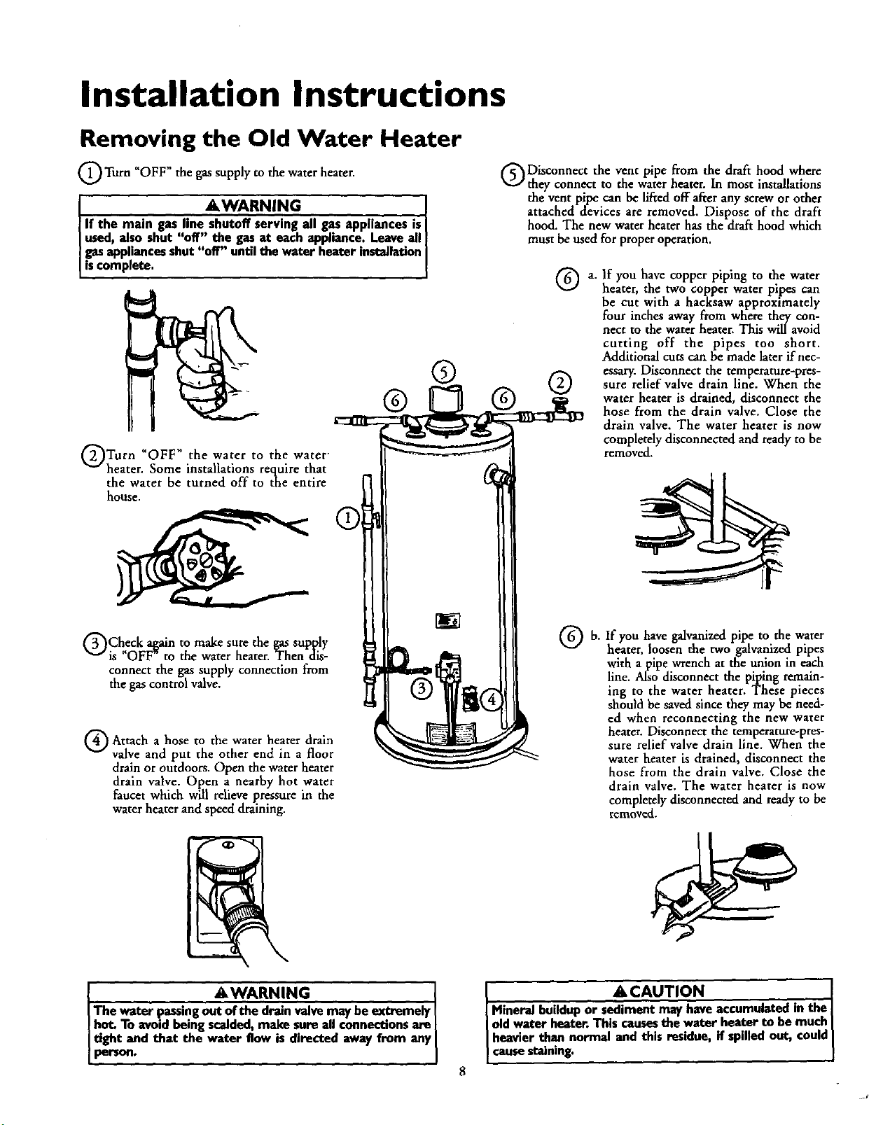
Removing the Old Water Heater
_OWW"the the heater.
Turn gassupply to water
AWARNING . ]
I If the main gas line shutoff serving all gasappliances isI
[ used, also shut "off" the gas at each appliance.Leaveall]
gasappliancesshut "off" until the water heater installation|
[is complete. I
Turn "OFF" the water to the water
heater. Some installations require that
the water be turned off to the entire
house.
Disconnect the vent pipe from the draft hood where
they connect to the waterheater. In most installations
the vent pipe can be lifted off after any screw or other
attached devices are removed. Dispose of the draft
hood. The new water heater has the drafthood which
must be used for proper operation.
a.
®
If you have copper piping to the water
heater, the two copper water pipes can
be cut with a hacksaw approximately
four inches away from where they con-
nect to the water heater. This will avoid
cutting off the pipes too short.
Additional cuts can be made laterif nec-
essary. Disconnect the temperature-pres-
sure relief valve drain line. When the
water heater is drained, disconnect the
hose from the drain valve. Close the
drain valve. The water heater is now
completely disconnected and ready to be
removed.
Check a[,ain to make sure the gas supply
is "OFF to the water heater. Then dis-
connect the gas supply connection from
the gas control valve.
G Attach hose the heater drain
The water passingout ofthe drain valvemay be extremely
hot. To avoidbeing scalded,make sure all connectionsare
tight and that the water flow is directed awayfrom any
person.
a to
valve and put the other end in a floor
drainor outdoors. Open the water heater
drain valve. Open a nearby hot water
faucet which will relieve pressure in the
water heater and speed draining.
water
AWARNING
If you have galvanizedpipe to the water
heater, loosen the two galvanized pipes
with a pipe wrench at the union in each
line. Also disconnect the piping remain-
ing to the water heater. These pieces
should be saved since they may be need-
ed when reconnecting the new water
heater. Disconnect the temperature-pres-
sure relief valve drain line. When the
water heater is drained, disconnect the
hose from the drain valve. Close the
drain valve. The water heater is now
completely disconnected and readyto be
remove.
IL" A CAUTION
meral buildupor sediment mayhave accumulatedin the i
d water heater.Thiscausesthe water heater to be much
eavier than normal and this residue,if spilled out, could
sestaining.
8

Installation Instructions (cont'd)
Facts to Consider About the
Location
You should carefully choose an indoor location for the new
water heater, because the placement is a very important consid-
eration for the safety of the occupants in the building and for
the most economical use of the appliance. This water heater is
not for use in mobile homes or outdoor installation.
Whether replacing an old water heater or putting the water
heater in a new location, the following critical points must be
observed. '
• The location selected should be indoors as close as practical
to the gas vent or chimney to which the water heater vent is
going to be connected, and as centralized with the water pip-
ing system as possible. The water heater, as all water heaters,
will eventually leak. Do not install without adequate
drainage provisions where water flow will cause damage.
A CAUTION
WATER HEATERSEVENTUALLY LEAK: Installationof the
water heater mustbe accomplishedin sucha mannerthat if
the tankor anyconnectionsshouldleak,tee flowofwater will
not causedamageto the structure.For this reason,it is not
to installthewater heater inan atticor upperfloor.
When suchlocationscannotbe avoided,a suitabledrain pan
shouldbe installedunder the water heater.Drain pansare
availableat yourload Searsstore.Sucha drain panmust be
not grenterthen I Y2inchnsdee_ havea mlnlmum kmgthand
of at least2inchesgreaterthan the water heaterdimen-
sions_ mustbe pipedto anadequatedrain.The pan must
notrestrictcombestionairflow.Undernodrcumstaneasisthe
manufactureror Searsto be heldliableforanywater damage
in €onnectinnwiththis water beater.
• The location selection must provide adequate clearances for ser-
vicing and proper operation of the water heater.
AWARNING
Thiswater heater mustnot be installeddirectlyonearpeting.
Carpeting must be protected by a metal or wood panel
beneaththe app lanceextendingbeyondthe ful _dth and
depthof the appliance by at least 3 inches(76.2mm) in any
direction,or if the applianceisinstalledin an akove or duset,
the entire floormustbe coveredbythe paneLFailureto heed
this warningmayresultinafire hazard.
AWARNING
Minimum clearancesbetween the water heater end com-
bustibleconstructionare I" at the r_dusand rear, 4" at the
frout,and 6"from the ventpipe.Cleanmcefromthe tep ofthe
_cket is 18"onmost models.Note that a lesserdimensionmay
be allowedon somemodek. Referto the labelon the water
heateradjacentto thegascontrolvalvefor alldearance_
VENT_TION
OPENINGS
AWARNING
INSTALLATIONSIN AREASWHERE FLAMMABLEUQUIDS
(VAPORS) ARE lIKELY TO BE PRESENT OR STORED
(GARAGES, STORAGE, AND UTILITY AREAS, ETC):
Flammableliquids(suchasgasoline,solvents,propane(LP) or
butane, etc.), all of which emit flammable vapors, may be
improperlystoredor usedin suchareas.The gaswater heater
pilot lightor mainburneram ignitesuchvapors.The resulting
Rashbeckandfirecancausedeathor seriousburnsto anyonein
thearea,aswellesproperty_.
If inst_latieninsuchareasisyouronlyoption,thenthe ias_din-
tion must be aCcomplishedin a waythat the pilot flame and
mainburner eameam elevatndfromtheflenr at least18inche_
While this n_/reduce the chancesof flammablevaporsfrom a
floorsp,Ibeingignited,gasolineandotherflammablesubmmces
shouldneverbe storedor usedinthe sameroom or areacon-
talninga gaswaterheateror otheropenflameor sparkproduc-
ingappliance.
NOTE: Flammablevaporsmaybe drawnbyair currentsfrom
otherereusofthestructuretotimappliance.
AWARNING
Propellants of anrosolspraysandvolatilecompounds,(clean-
ers,chlorinebasedchemicals,refrigerants,etc.)in additionto
beinghighlyflmnmable.in manycases,will alsochangeto .cor-
rosive hydroch|orlcacidwhen exposedto the combustion
productsof the water heater.The resultscanbe hazardous,
and also cause productfailure.
I Figure ! I
AWARNING
A gaswater heater cannotoperateproperlywithoutthe cor-
rectamount of air for combustion.Do not installin a confined
areasucha duset,unlessyou provideair as shownin Figures
I-5. Never obstructthe flowof ventilationair. Ifyou haveany
doubtsorquestionsat all,callyourgascompany.Failureto pro-
videcheproper_mt ofcombes6onair am resultina life or
explosionand can causeDEATH, SERIOUSBODILY INJUI_,
OR PROPERTYDAMAGE.
AWARNING
If thiswater heaterwifibe usedin beautyshops,barbershops,
cleaningestablishments,or self-servicelaundrieswith dry
cleaningequipment,it is imperativethat the water heateror
wa_erheatersbe installed sothat combustion andven_
Bir betakenfrom outsidethese areas.Referto the "Facts to
ConsiderAboutthe Location"sectionof this manualandalso
thelatestedition of the NationalFuelGasCode,ANSI Z223.1,
alsoreferredto as NFPA 54 for specificsproddedconcerning
air required.

Installation Instructions (cont'd)
Combustion Air and Ventilation
for Appliances Located in
Unconfined Spaces
Unconfined Space is a space whose volume is not less than 50
cubic feet per 1,000 Btu pet hour of the aggregate input rating
of all appliances installed in that space. Rooms communicating
directly with the space in which the appliances are installed,
through openings not furnished with doors, ate considered a
part of the unconfined space
In unconfined spaces in buildings, infiltration may be adequate
to provide air for combustion, ventilation and dilution of flue
gases. HoWever, in buildings of tight construction (for exampl€,
weather stripping, heavily insulated, caulked, vapor barri€r, etc.),
additional air may need to be provided using the methods
described in Combustion Ait and Ventilation t'orAppliances
Located in Confined Spaces, b.
Combustion Air and Ventilation
for Appliances Located in
Confined Spaces
Confined Space is a space whose volume is less than 50 cubic
feet per 1,000 Bm per hour of the aggregate input ratingof all
appliances installed in that space.
a. ALL AIR FROM INSIDE BUILDINGS.
(See Page9 Figure 1,and Figure2 below)
The €onfined space shall be provided with two permanent
openings communicating directlywith an additional room(s)
of suiTlcient volume so that the combined volume of all
spaces meets the criteria for an unconfined space. The total
input of all gas utilization equipment installed in the com-
bined space Mall be consideredin making this determination.
Each opening shall have a minimum free areaof one square
inch per 1,000 BTU per hour of the total input rating of all
gas utilization equipment in the confined space, but not less
than 100 square inches. One opening shall commence within
12 inches of the top and one commencing within 12 inches
of the bottom of the enclosure.
1. When directly communicating with the outdoors, each open-
ing shallhave a minimum free areaof 1square inch per 4,000
BTU per hour of total input rating of all equipment in the
€ndosure. (SeeFigure 3.)
2. When communicating with the outdoors through vertical
ducts, each opening shall have a minimum free area of 1
square inch per 4,000 BTU per hour of total input rating of
all equipment in the endosure. (See Figure 4.)
Figure 4 ]
3. When communicating with the outdoors through horizontal
ducts, each opening shall have a minimum free area of l
alsctuareinch per 2,000 BTU per hour of total input rating of
equipment in the enclosure. (SeeFigure 5.)
_L_IEy Off Otd VEIcr
V_Tga_'flO_ LO_EF*O
b. ALL AIR FROM OUTDOORS: (seeFigures3-5)
The confined space shall be provided with two permanent
openings, one commencing within 12 inches of the top and
one commencing within 12 inches from the bottom of the
enclosure. The openings shall communicate directly, or by
ducts, with the outdoors orspaces (crawl or attic) that freely
communicate with the outdoors.
IFI re']
Figure 5 ]
4. When ducts are used, they shall be of the same cross-sectional
area as the free area of the openings to which they connect.
The minimum short side dimension of rectangularair ducts
shall not be less than 3 inches. (SeeFigure 5.)
5. Louvers and Grilles: In calculating free area, consideration
shall be given to the blocking €ffect of louvers, grilles or
screens protecting openings. Screens used shall not be smaller
than ¼ inch mesh. If the Free area through a design of louver
or grille is known, it should be used in calculating the size
opening required to provide the free area specified. If the
design and free area is not known, it may be assumed that
wood louvers will be 20-25 percent free areaand metal louvers
and grilles will have 60-75 percent free area. Louvers and
grilles shall be fixed in the open position or interlocked with
the equipment so that they are opened automaticallyduring
equipment operation.
6. Special Conditions Created by Mechanical Exhausting or
Fireplaces: Operation of €xhaust fans, ventilation systems,
clothes dryers or fireplacesmay create conditions requiring
special attention to avoid unsatisfactory operation of installed
gasutilization equipment.
10

Installation Instructions (cont'd)
Water Piping
AWARNING
HOTTERWATERCAN SCALI_.Water heatersam intendedto
producehotwater.Waterheatodto a W.._yhi_ *dll
satisfydod_ washln&dishwashin&andothersanitizingneeds
(an scaldandpermanentlyInjureyouuponcontact.Somepeo-
_eare morelikelyto be penmanentlyinjuredbyhotwater b_an
otherL Theseincludethe eklerl_chlldmrkthe infirm,or physical-
ly/mentallyhandicapped.Ifanyoneusinghotwater inyourhome
fitsintooneulthese greupsorIf thereisalocal€odeor statelaw
requiringacertaintemperaturewaterat_ hotwaterta_ then
mumusttakespecialpmceutienLIn addidouto usingtbelowest
x_ibin temperaturesettingthat sallsfiesyourhot waterneeds,
Lmeanssuchasa mixingvalve,shouldbeusedat the hotwater
tapsusedbythese peophor at thewaterheatenMixingvalves
areavailableat plumbingsupplyor hardwarestore_Followman-
ufacturersinstructions for installationof the valves.Before
changingthe factory setting on the thermostat, read the
_l'emperatore Regulation"sectioninthismanual.
This water heater shall not be connected to any heating systems
or component(s) used with a non-potable water heating
appliance.
If a water heater is instal|ed in a dosed water supply system;
such as one having a back-flow preventer, check valve, water
meter with a check valve, etc.., in the cold water supply; means
shall be provided to control thermal expansion. Contact the
local utility or local Sears Service Center on how to control this
situation.
NOTE: To protect against untimely corrosion of hot and
cold water fittings, it is strongly recommended that all-elec-
tric unions or couplings be installed on this water heater
when connected to copper pipe.
• Look at the top cover of the water heater. The cold water
inlet is marked-cold. Put two or three turns of teflon tape
around the threaded end of the threaded-to-sweat coupling
and around both ends of the ¾"threaded nipple. Using flexi-
ble connectors, connect the cold water pipe to the coldwater
inlet of the water heater.
NOTE: This water heater is super insulated m
heat loss from the tank. Further reduction in heat loss
can be accomplished by insulating the hot water lines
from the water heater.
INSTALLATION COMPLETED USING
SEARS INSTALLATION KIT
FLEXIBLE
HOT OUTLET
TO HOUSE /
THREADED TO
SWEAT COUPLING
314" THREADED
COUPLING
WATER
CONNECTORS
SHUTOFF
VALVE
THREADED TO
SWEAT COUPLING
314" THREADED
COUPLING
WATER LINE
COLD INLET
The illustration shows the attachment of the water pipin_ to the
water heater. The water heater is equipped with ¼ inch water
connections.
NOTE: If using copper tubing, solder tubing to an adapter
before attaching _e adapter to the cold water inlet enunec-
tion. Do not solder the cold water supply line directly to the
cold water inlet. It will harm the dip tube and damage the
tank.
• Look at the top cover of the water heater. The water oudet is
marked hot. Put two or three turns of teflon tape around the
threaded end of the threaded-to-sweat coupling and around
both ends of the ¾ threaded nipple. Using flexible connec-
tors, connect the hot water pipe to the hot water oudet on
the water heater.
11
[]
PRESSURE
RELIEF VALVE
PiPE (Do not cap
or plug)
6" AIR GAP
FLOOR DRAIN

Installation Instructions (cont'd)
Temperature-Pressure Relief Valve
_WARNING
At the time of manufacturethis water heaterwas provided
witha combinationtemperature.pressuresraliofvalvecertified
by a nationallyrecognizedtestinglaboratorythat maintains
.p_'odic inspectionof productionof listedequipmentor mete-
rmals,as meeting the requirements for Relief Valves and
AutomaticGasShutoffDevicesforHot Water SupplySystems,
andthe latestedition ofANSI Z21.22 and the coderequire-
!mentsof ASME.If replaced,the valvemustmeetthe require-
menu ofIoealcodes,but notlessthana combinationtempera-
ture and pressurerelief valvecertifiedasmeetingthe require-
mentsforReliefValvesandAutomaticGasShutoffDevicesfor
Hot Water SupplySystems,ANSI Z21.22bya nationallyrecog-
nizadtesting laboratorythat mmntainsperiodicinspectionof
productionof listedequipment ormaterials.
The valvemust he markedwith a maximumsat pressureloot
to exceedthe marked hydrostaticworkingpressureof the
waterheater(IS0 II_J_, in.)anda dischargecapacitynot less
thanthe waterheaterinputrate asshownonthemodelrating
plate.(Electricheaters• watts dividedby 1000x 3415 equal
BTU/Hr.rate.)
Yourlocaljurisdictionalanthori_, whilemandatingthe useofa
temperature-pressurereliefvalvecomplyingwithANSI Z21.22
andASME, mayrequire a valvemodeldifferentfromthe one
fomishedwiththewakerheater.
Compliancewithsuchlocalrequirementsmustbe satisfiedby
the installerorenduserof the water heaterwith a locallypre-
scribedtemperature-pressurereliefvalveinstalledinthe desig.
natedopeningin thewater heaterin placeofthefactoryfur-
nisbedvalve,
Forsafeoperationofthewater heater,the reliefvalvemustnot
beremovedfromit_ designatedopeningorplugged,
IThetemperature-pressurereliefvalvemustbe installeddirectly
intothefittingofthewaterheaterdesignatedfor thereliefvalve.
Positiontilevalvedownwardend providetubingsothat anydis-
chargewill exitonlywithin6 inchesabove,or at anydistance
belowthe structuralfloor.Be certainthat no contact ismade
withanyliveelectricalpart.Thedischargeopeningmustnotbe
blockedor reducedinsize underanycircumstances.Excessive
length,over30 feet,or useofmorethan fourelbowscancause
restflcdonandreducethedischargecapacityofthevalve.
No valveor otherobstructionisto he placedbetweenthe relief
valveandthetank.Do not connecttubingdirectlyto discharge
drainunlessa6" airgapisprovided.Topreventbodilyinjury,hez.
ardto life,or propertydamagethe reliefvalvemustbeallowed
to dischargewater inquantitiesshouldc_rcumstancesdemand.If I
the dischargepipeisnotconnectedto a drainor othersuitable
means,thewaterRowmaycausepropertydamage,
TheDischargePipe:
• Mustnot be smallerin sizethanthe outlet pipesizeof the
valve,orhaveanyreducingcouplingsor otherrestrictions.
• Mustnetbepluggedorblocked.
• Mustbeofmateriallistedfor hotwater distribution.
I. Mustbe installedsoasto allowcompletedrainageofboth
the temperature.pressurerelief valve,and the discharge
pipe.
• Mustterminateat anadequatedrain.
• Mustnothaveanyvalvebetweenthe reliefvalveandtank.
AWARNING
The temperature-pressure relief valve must be manually
operatedat leastoncea yea_ Cautionshouldbe takento
ensurethat (I) no one is infrontof or aroundthe outletof
the temperature-pressurerelief valvedischargeline,and (2)
the water manually dischargedwill not causeany bodily
injury or property damage because the water may be
extremelyhot.
If after manuallyoperatingthe valve,it failsto completely
resetand continuesto releasewater,immediatelydosethe
coldwater inlet to the water heater, follow the draining
instructions,and replace the temperature-pressurerelief
valvewith a newone.
HOT
SHUTOFF COLD
VALVE
"EHPERATURE-
PRESSURE
RELIEF VALVE
(Do not cap or plus)
[]
6" AIR GAP
RELIEFVALVEOPENING
At the time of _ocu_, thiswater heaterwas providedwith a combinationtem-
perature-pressurerelief valvelisted ascomNyfeg with the standa_lfor rdiet"valvesand
automatic gasshut-offdevices for hot war_r supplysystems,ANSi Z21.22. For safe
operationof the water heater,the _lef valvemust not be removed from its designated
ypOouintof instaibtion cr plugged.
r load urisdictiona{authori_, while mandatingthe use of a tem_rature-pre_sure
re{ief valvecomplyingwithANSI 7-.21,22andASPIE,mayrequire a _alvemodel dfferent
fromthe one furnishedwith the water heater
Compliancewith suchlocal requirements must be satisfied by the ins_ler or end user
of the water heater with a locallyprescril_ temperature-pressure relief valveinstalled
in the designatedopeninginthe water heater
See manual heading-'q'ernperature-FYessureRelief Valves"for instalbtion and mainte-
nance of relief valve,dischargeline,and other safer7 precautions.
12

Installation Instructions (cont'd)
Filling the Water Heater
A CAUTION
Neverusethisvrat_rheater unlessit iscompletelyElledwith I
water. To preve_ damnge to the tenk, the tenk must be filled I
with water. Water must flow from the hot water faucet
before turn ng ' ON ' gas to the water beater.
To fill the water heater with water:
• Close the water heater drain valve by turning the handle to
the right (clockwise). The drain valve is on the lower front of
the water heater.
Open the cold water supply valve to the water heater.
NOTE: The cold water supply valve must be left open
when the water heater is in use.
To insure complete filling of the tank, allow air to exit by
opening the nearest hot water faucet. Allow water to tun
until a constant flow is obtained. This will let air out of the
water heater and the piping.
• Check all new water piping for leaks. Repair as needed.
Venting
Ai.WARNING
VENT DAMPERS - Any vent damper, whether it is operated
thermally or otherwise must be removed ifitsuseinhibit3 prop-
er drafting of the water heate_.
Thermally Operated Vent Dampers: Gas-fired water heaters
havingthermal efficiency in eacessof 80% may produce a rela-
tively lowfluegastemperature. Such temperatures maynotbe
high enough to properly open thermally operated vent
dampers. This wonld ceuse spillageof flue gasasand rnay canse
ced_on monoKidepoisoning.
Vent dampen must bear evidenceof certification ascomplying
with the latest edition of American National Standard ANSI
Z21.68 (ANSI Z21.66 & 67, respecd_, cover electrically and
mechanically actuated vent dampers). Before installationof any
vent dampe_ comuit your local SearsServiceCenter or the gas
utility for further information.
&WARNING
To insureproper ventingof this gas-firedwater heater,the
correctvent pipediameter mustbe utilized.Any additionsor
deletionsof othergasapplianceson acommonvent withthis
water heatermayadversely_q_ct the operationof thevm_r
heater,Consultthe localSearsServiceCenter or gasutilityif
anysuchchangesareplanned.
For proper venting in certain installations, a larger diameter vent
pipe may be necessary. Due to great variances in installations,
unforeseeable by the manufacturer of the water heater, you must
consult your gas company to aid you in determining the proper
venting for your water heater from the vent tables in the latest edi-
tion of the National Fuel Gas Code ANSI Z223.1, also referred to
as NFPA 54.
Check the venting system for signs of obstruction or deterioration
and replace if needed.
The combustion and ventilation air flow must not be obstructed.
AWARNING
Obstructedor deter_ratedventsystems_ presentaserious
healthriskor asphyxiation.
• Place the draft hood legs in the receiving holes on the top of
the water heater. The legs will snap in the holes to give a tight
fit.
• Place the vent pipe over the draft hood. With the vent pipe in
position, drill a small hole through both the vent pipe and
draft hood. Secure them together with a sheet metal screw.
DRAFT HOOD _ _VENT'_I I _'
.... _ ISCRE__._I _DRAFT HOOD
--a L_VENT TO OUTDOORS OR
DRAFTHC_Off'-J_-cH''NtY
A,WARNING
I The water heater with draft hood inmdled must be properly I
vented to a chimney which terminates outdoor_ Never oper-
I atethe waterheateranlessit isventedtotbeontdonrsandhasI
I edequateair.su.pPlyte aveidrisksof improperoperation,explo-I
I I
AWARNING I
The vent pipe from the water heater must be no lessthan the I
diameter of the draft hood outlet on the water heater, and
13

Installation Instructions (cont'd)
Venting (cont'd)
All vent gases must be completely vented to the outdoors of the
structuze (dwelling). Installonly the draft hood provided with
the new water heater and no other draft hood.
Vent pipes must be secured at each joint with sheet metal screws.
TO
CHIMNEY
l
VENT PIPE INSTALLATION
There must be a minimum of 6" cleaeance between single wall
vent pipe and any combustible material. Fill and seal any dear-
ancebetween single wall vent pipe and combustible material
with mortar mix, cement, or other noncombustible substance.
For other than single wall, follow vent pipe manufacturer's clear-
ance specifications. To insure a tight fit of the vent pipe in a
brick chimney, seal around the vent pipe with mortar mix
cement.
AWARNING
Failureto haverequired clearancesbetweenventpipingand
€ombusttl_ematerialwillresultina firehazard.
Besurevent Ixpeis prnperlyconnectedto prexentescapeof
I . AWARNING I
dangerousfluegaseswhichcouldcausedeadly_spl_dation.
Gas Piping
AWAJRNING
Hake sure the gassuppliedis the same type listed on the
modelrating plate. The inlet gaspressuremustnot exceed
10.5in.water column(2.6kPa)for naturalgasor 13in. water
column(3.2kPa) for propane(/E) gas.The minimum inlet
gaspressureI"..L_ on the modelrating plate isfor the pur-
poseofinputadlUStmant.
I AWARNm(; I
If the gascontrolvalveis subjectedto pressuresexceeding½
poundper squareinch(3.5kPa),the _ to the gascon-[
trnl valvecouldresultin afireor explosionfrom leoldnggas. I
AWAR_I. ING I
[ If the maingasline shutoffsorwng all gasappliancesisused,I
alsoturn "of/" the gasat eachappi.uu_e..Leaveallgasappii-
I antesshutoffuntilthe waterheater matailationiscomplete. I
A gas line of su_cient size must be run to the water heater.
Consult the latest edition of National Fue! Gas Code ANSI
Z223.1, also referred to as NFPA 54 and the gas company con-
cerning pipe size.
There must be:
• A readily accessiblemanual shut off valve in the gas supply line
servingthe water heater, and
• A drip leg (sediment trap) aheadof the gas control valve to hdp
prevent dirt and foreign materials from entering the gas control
Valve.
• A flexible gas connector or a ground joint union between the
shutoff valveend control valveto permit servicingof the unit.
AWARNING
Chemical vapor corrosionof the flue and vent systemmm/
Occurif air for combustioncontainscertain chemicalvapor_
Spraycan propellants,cleaningsolvents,refrigerator and air
conditionerrefrigerants,swimmingpool chemicals, caJcium
andsodiumchloride,waxes,bleach,andprocesschemicalsare
typicalcompoundswhich arepetandallycorrosive.
Be sure to check all the gas piping for leaks before lighting the
water heater. Use a soapy water solution, not a match or open
flame. Rinse offsoapy solution and wipe dry.
Standard Models are for installation up m 3,300 feet above sea
level.
Altitude Mode_ are for installation from 3,300 to 5,500
feet abovesea level.
Ifa standard model is installed above3,300 feet or a high aldmde
model is installed above 5,500 feet, the input rating must be
reduced at the rate of 4 percent for each 1,000 feet above sea levd,
Contact your local Sears Service Center or gas utility for further
information.
_,WARNING
The applianceand its gas connectionmust be leak tested
beforeplacingthe appliancemoperation.
14

Installation Instructions (cont'd)
AWARNING
. Tbe appEanceaed its individueJsbetoffvalve must be discon-
nected from the gassupplypipingsym_n during any pressure
testing of the gas system at test pressures in excess of 'A
poundper squareinch (3.5k1%).
. The appliancemustbeisobtedfromffmgassupplypipingsys-
tem bydosing i_ individual manual shutoffvalve during any
pr--_ure tosting of the gas supply pipingsystem at test pres-
suresequal or lessthan _ pound per square inch (3.SkPa_
I AWARNING I
Use pipe joint compound or teflon tape marked as being
resistantto tbeactionof peU'oleum[Propane(LR)] gases. I
SEDIMENT TRAP
A sediment trap shall be installed as close to the inlet of the
water heater as practical at the time of water heater installation.
The sediment trap shall be either a tee fitting with a capped nip
pie in the bottom outlet or other device recognized as an effec-
tive sediment trap. If a tee fitting is used, it shall be installed in
conformance with one of the methods of installation shown
below.
Connecting the gas piping to the gas control valve of the water
heater can be accomplished by either of the two methods shown,
GAS PIPING WITH
FLEXIBLE CONNECTOR
GROUND
UNION(Optional)
DRIP LEG
(Sedimenttrap)
CAP
LOOP
GAS
CONTROL
VALVE
GAS PIPING WITH ALL BLACK IRON
PIPE TO GAS CONTROL
GROUND IO!NT -_ BLACK PIPE
UNION(Op_on_)__ /
CO NTVALvP_EOL
AWARNING
Contaminonts in the gas lines may cause improper operatinn
of the gas €ontrol valve that may rasult in Ere or explosion.
Bofore attaching tbe gasline be sure that afl Ips pipe is dean
on the imide. To trap any dirt or foreign n_ter_l in the gas
supply line, a drip leg (sometimes called a sediment trap)
must be incorporated in the piping. The drip leg must be
readily accessible.Install in accordance with the '_,as Piping"
section. Refer to the latest edition of the National Fuel Gas
Code, ANSI 7.223.1, also referred to asNFPA 54.
3"
_-J CAP
15

Installation Instructions (cont'd)
Installation Checklist
BEFORE LIGHTING THE PILOT:
* Check the gas lines for leaks.
a. Use a soapy water solution• DO NOT test for gas leaks
usinga match or open flame.
b. Brush the soapy water solution on all gas pipes, joints and
fittings.
c. Check for bubbling soap• This means you have a leak.
Turn OFF gas andmake the necessary repairs.
d. Recheck for leaks.
e. Rinse offsoapy solution and wipe dry.
• Is the new temperature-pressure relief valve properly installed
and piped to an adequate drain? See Temperature-Pressure
ReliefValve section.
• Are the cold and hot water lines connected to the water
heater correctly. See Water Plpmg mstrucnons in the
"Installation Instructions" section.
• Is the water heater completely fdled with water? See "Filling"
instructions in the _Installation Instructions" section.
• Will a water leak damage, anything? See the "Facts to
Consider About the Location section.
• Is there proper clearance between the water heater and any-
thing that might catch fire? See the Facts to Consider About
the Location" section.
HOT
GAS SUPPLY
VENT PIPE TO UNION
OUTDOORS \
OR CHIMNEY _1 SHUTOFF VALVE
DRAFT HOOD
SHUTOFF VALVE
_ TEMPERATURE-
PRESSURE
RELIEF VALVE
DISCHARGE PIPE
(Do not cap or plug)
• Do you have adequate ventilation so that the water heater
will operate properly. See Combustion Air and Ventilation
in the "Factsto Consider About the Location" section.
• is the draft hood vent piping properly secured? See "Venting"
mstrUCtlOnS in the Installation Instructions seenon.
• Is there proper clearance between the vent pipe and anything
that might catch on fire_ See Venting instructions in the
"Installation Instructions section.
• Is the vent pipeproperly sloped and does the vent terminate
outdoors. _ee "Venting instructions in the Installation
Instructions"section.
Do you need to call your gas company to check the gas pipe
and its hookup?
TEE
(Sediment
trap) PIPE CAp
DRAIN VALVE
6" AIR GAP
FLOOR DRAIN
16
MODEL RATING PLATE

Operating Instructions
Lighting
AWARNING
BEFORE LIGHTING [PROPANE (L.R) GAS WATER
HEATERS]: Propane (I.R) gasb henvierthan air. Should there
be a leak in the system, the gas will settle near the ground.
Basements, crawl spaces, skirted areas under mobile homes
(even when vendlatod_ closetsand areasbelow ground level will
serve as pockets for the accumulation of this gas. Before
attempting to light or relight the water heater's pilot or turning
on a nearby electrical light switch,be absolutelysure there b no
accumulated gasin the area. Searchfor odor of gasby sniffingat
ground levelin the Vicinity of the appliance.If odor isdetected,
follow stepsindicatedat "For Your Safety" on the cover page of
this manual then leavethe promises.
Lighting and operating instructions are located on front of the
water heater, above or to one side of the gas control valve.
_WARNING
AN ODORANT IS ADDED TO THE GAS USED
BY THIS WATER HEATER.
FOR YOUR SAFETY
IF YOU SMELL GAS:
• Do not try to light anyappliance.
• Do not touch anyelectrical switch;do not useany phone in
your building.
• Immediately callyour gas suppiierfrom a neighbor's phone.
Follow the gassuppliers inm'uctions.
• If you cannot reach your gas supplier, call the fire depart-
ment.
Figure 7 1
AWARNING
DO NOT forcethe gascontrolknob,Use onlyyour handto
pushit downto lightthe pilot, or to tom it to "ON" "OFF"
or "PILOT". Never usea toolsuchasa lever,wrenchor pli-
ers.Do not hit or damagethe knob.A damagedknobmay
result in an explosionand seriousinjury.If youhaveproblem
turning the Imob,callthegassupplierimmediately.
CHECK FOR LEAKS
Be sure to check all your gas pipes for leaks before lighting your
water heater. Use a soapy water solution, not a match or open
flame. Check the factory gas fittings after pilot is lit and gas con-
trol knob is still in _PILOT" position. Then, check the fittings
when the main burner is turned tON". Use a soapy water solu-
tion for this, too.
17
Figure 8 I
Figure 9 1
__NNER DOOR
OUTER
DOOR

Operating Instructions (cont'd)
Lighting label on the water heater as it appears above the thermostat
FOR YOUR SAFETY READ BEFORE LIGHTING
If you do not follow these instructions exactly, a fire or explosion
may result caus ng property damage, persona njury or loss of life.
A. Thisappliancehasa pilot which must be lightedby
hand.Whenlightingthepilot,followtheseInstructions
exactly.
B,BEFORELIGHTINGsmellall aroundtheappliancearea
for gas. Be sure to smell next to the floor because
somegasis heavierthenairandwill settleonthefloor.
WHATTODO IFYOUSMELLGAS
• Donot fryto lightanyappliance.
• Do not touch any electric switch; do not useany
phonein yourbuilding.
• Immediatelycallyourgas supplierfroma neighbor's
phone.Followthegas suppUer'sinstructions,
WARNING I
LIGHTING INSTRUCTIONS
1.STOP!ReadthesafetyInformationaboveonthislabel.
2,Removeouterdoor.
3. Set the thermostatto lowestsettinLby turning the
watertemperaturedial clockwise,(( "_)to itslowest
temperaturesetting(witharrowondial)as shown.DO
NOT FORCE,
4.Turngas controlknobclockwise_ to "OFF" posi-
tion. Knob cannotbe turnedfrom "PILOT" to "OFF"
unlessknob Is depressedslightly.DO NOT FORCE.
(Figure6, page17)
5. Waitfive (5) minutestoclearout anygas. If youthen
smellgas, STOPIFollow"B" inthe safetyinformation
aboveon this label.If youdon't smellgas, go to the
nextstep.
6. Remove(or open) inner door locatedbelow the gas
control unit.
7. Findpllot-loitowmetaltubefromgascontrol.Thepilot
IslocatedInfrontoftheburner
PILOT BURNER ._ THERMOCOUPLE
8. Ifyoudon'tsmellgas,turnknobongascontrolcounter
dockwise_@ to"PILOT"position.(Figure7, page17)
• If you cannotreach your gassupplier,callthefire
department.
C. Useonly yourhandtopushin or turnthe gascontrol
knob.Neverusetools.If theknobwillnot pushInor
turnby hand,don'ttryto repairIt, calla qualifiedser-
vicetechnician.Forceor attemptedrepairmayresult
ina fireorexplosion.
D. Do not usethisapplianceif anyparthas been under
water.Immediatelycall a qualifiedservicetechnician
toinspecttheapplianceandto replaceanypart of the
controlsystemand anygas controlwhichhasbeen
underwater.
9. Push in control knob all the wayand hold down.
Immediatelylightthe pilotwitha match.Continueto
holdcontrol knob in for aboutone (1) minute after
the pilot islit. Releaseknobend it will pop back up.
Pilotshould remainlit. If it goesout, repeatsteps3
through8.
• Ifknob doesnotpop upwhenreleased,stopand
immediatelycall yourservicetechnicianor gas
supplier,
• If the pilotwill not stay lit after severaltries,
depress__ andturnthe gas controlknobclockwisetechnician=;
V to"OFF"and sell yourservice
or gassupplier.(Figure6,page17)
10. Replace(orclose)innerdoor.Replaceouterdoor if
door doesnotcovergas controlon/offknobortem-
peratureadustmentknob.(Figure9,page17)
11. At arms engthaway,turngascontrolknobcounter-
clockwise(_ to the full "ON" position. Warning
do not use gas control knob to regulate gas
flow. (Figure8,page17)
12.At arms lengthaway,set the thermostatto desired
setting. The mark ( • ) indicativeof approximate
120°F is preferred starting point. Some local laws
may requirea lowerstartingpoint. If hotterwater is
desired,seeinstructionmanualand"warning"below.
13,Replacetheouterdoorifnotreplacedinstep 10.
WARNING
HotterwaterIncreasesthe riskof scaldinjury.Before changingtemperaturesettingseeinstructionmanual.
TO TURN OFF GAS TO APPLIANCE
1. Set thethermostatto lowestsetting byturningthe
watertemperaturedialclockwise(F"_) to its lowest
temperaturesetting(witharrowon dial)as shown.DO
NOT FORCE,
2. Turn gas controlknob clockwise !_,; to "OFF"
position. Knob cannot be turned from "PILOT" to
"OFF" unlessknob is depressedslightly.OO NOT
FORCE,
3.Replaceouterdoor(ifremoved),
]8

Operating Instructions (cont'd)
Temperature Regulation
Due to the nature of the typical gas water heater, the water tem-
_oeratute [rt certain situations may vary up to 30°F higher or
wer at the point of usesuch as, bathtubs, showers, sink, etc.
This means that when the temperature ad)ustment dial is set at
the mark approximating 120 ° F, the actual water temperature at
any hot water tap could be as high as 150°F or as low as 90°E
Any water heater's intended purpose is to heat water. Hot water
is needed for cleaning (bodies, dishes, clothing). Hot water will
present ascald hazard. Depending on the time element, and the
people involved (normaladults, children, toddlers, elderly,
infirm, etc.) scalding may occur at different temperatures.
AWARNING
HOTTERWATERCAN SCAI._.Wa_" hoatersareintendedto
i_d...ucehot water..Water heatedto a temperature whichwill
satisfyclotheswashm&dishwashing,andothersanitizingneeds
canscaldandpermanentlyinjureyouuponcontact.Somepe_
piearemore likelyto bepermanentlyinjuredbyhot waterthan
othe_ Theseincludetheelder_,children,the infirm,or physical-
lylrn_€ handicapped. Ifanyoneusinghot water inyourhome
fitsintoone ofthesegroupsor ifthereisalocalcodeorstatelaw
requiringa certaintemperaturewaterat thehotwatertap,then
roumusttakespecialprecautions.Inadditionto usingthe lowest
3os_le temperaturesettingthatsatisfiesyourhotwater needs,
i meanssuchasamixingvalve,shouldbe usedat the hot water
tap_usedbythese peopleor at the water heater.Mixingvalves
areavailableat plumbingsupplyorhardwarestores.Followman-
ufacturersinstructionsfor installationof the valves.Before
changingthe factory setting onthe thermostat, read the
'rl'emperatureRegulation"sectioninthis manual.
Turn the water temperature dial dockwise (_'_) to decrease
the temperature, or counterclockwise (_-"_) to increase the
temperature.
PILOT LIGHTING-Set here before attempting to light pilot.
A-Is a thermostat setting of approximately
120°F, which will supply hot water at the
most economical temperatures. The
temperature adjustment knob Can be
turned lower than 120°F if desired.
A-Is a thermostat setting of approximately
130°E
B-Is a thermostat setting of approximately
140°E
AWARNING
NeveraUowsmallchildren_ousea hot water top, or to drasv_
their ownbathwater.Never leaveachildor handicappedper-
sonunattendedina bathtubor shower. I
The thermostat of this water heater has been factory set at its
lowest position, to reduce the risk of scald injury. It is adjustable
and must be reset to the desired temperature setting. The mark
(A) indicative of approximately 120°F is the preferred starting
point. Some states have a requirement for a lower setting. If you
need hotter water, follow directions for temperature adjustment,
but beware of the warnings in this section.
C-Is a thermostat setting of approXimately
150°E
VERY HOT-Is a thermostat setting of 160°E It is
recommended that the dial be set lower
whenever possible.
NOTE: Water temperature range of 120°--140°F recom-
mended by most dishwasher manufacturers.
AWARNING
Shouldoverheatingoccur or the gassupplyfail to shut off,
torn OFF' the manualgas€ontro valveto the applance.
19J

Service and Adjustment
Tank (Sediment) Cleaning
Sediment build-up on the tank bottom may create varying
amounts of noise, and if left in the tank will cause premature
tank failure. In some water areas, you may not be able to drain
all sediment deposits by simply draining the tank. In these cases
Mag Erad (part no. 23600) can be used to help remove the sedi-
ment deposits. This may be ordered from the Sears Service
Center. For ordering, refer to the _Repair Parts" section.
Venting System Inspection
At least once a year a visual inspection should be made of the
venting system. You should look for:
Obstructions which could cause improper venting. The com-
bustion and ventilation air flow must not be obstructed.
Damage or deterioration which could cause improper vent-
ing or |eakage of combustion products.
• Rusted flakes around top of water heater.
&WARNING
Chemical vapor corrosion of the flue and vent system may
occur if air fur combustion contains certain chemical vapors.
Spray can propellants, cleaning solvents, refrigerator and air
conditioner refriger-_ts, swimming poo! chemicals, calcium
and sodium ch oride, waxes, bleach, and processchemicals an
typical compounds which are potentially corrosive.
I _WARNING
Obstructed or deteriorated vent systemsmay present a serious
heaJthriskor asphyxiation.
Burner Inspection
J AWARNING 7
Do not usethisappr_nceifanypartofit hasbeenunderwater.]
Immediately call a Sears ServiceTechnicianto respecttheJ
applianceand to.replace the gascontrol or any part of the I
burnersystemwhichhasbeenunderwater. |
At least once a _,ear a visual inspection should be made of the
main burner annpilot burner. The drawing is for your reference.
You should check for sooting which is not normal and will
impair proper combustion.
• AWARNING
Soot build-up indlcatesa problem that requires correction
beforefurtheruse.Turn"OFF" gasto water heaterand leave
"OFF" untilrepairsare made, becausefailureto con_ct the
causeof the sooting can resultin a fire or explosioncausing
DEATH,SERIOUSBODILYINJURY,OR PROPERTYDAMAGE.
Burner Cleaning
&,.WARNING I
Be sure the vent pipingts properly connected to prevent
e_. o.fdangerousflue gasseswhich could cause deadly
asphyxia_on.
• _,WARNING
If after inspection of the vent system you found sooting or
deterioration, something iswrong. Call the local gasutility to I
correct the problem and clean or replace the flue and venting I
[ before resum ng opera, on of the water heater. [
In the event your burner needs cleaning, use the following
instructions:
If inspection of the burner shows that cleaning is reouired, turn
the gas control knob clockwise (_x) to the "OF1 _" position,
depressing slightly.
NOTE: The knob cannot be turned from "PILOT" m "OFF"
unless knob is depressed slightS. DO NOT FORCE.
Loose deposits on or around the burner can be removed by care-
fully using the hose of a vacuum cleaner inserted through the
access door of the water heater. If the burner needs to be removed
for additional cleaning, call the Sears Service Center to remove
and clean the burner and correct the problem that required the
burner to be cleaned.
20

Service and Adjustment (cont'd)
L.P.Gas Control Valve & Burner
Assembly Replacement
Information
AWARNING
PROPANE (L.R) GAS CONTROL VALVE AND BURNER
ASSEMBLYREPLACEMENTINFORMATION.
ForPropane(LR) GasModelsOnlF.
Yourwater heater isequippedwith a Propane(L.R) gascon-
trol valveanda main burnerassemblywith left handthreads
forthe followingfittingsandtheir connections.
The connection between the manifold and the gas
control valve (A to B) are left hand threads.
The connection between the main burner orifice
and the manifold (C to D) are left hand threads.
For ordering these replacement parts, please refer to
the "Repair Parts" section of this manual.
Temperature-Pressure Relief
Valve Operation
The temperature-pressure relief valve must be manually operated
at least once a year.
TEMPERATURE-PRESSURE
RELIEF VALVE
/
DISCHARGE PIPE
Failure to install and maintain a new properly listed tempera-
ture-pressure relief valve will release the manufacturer from any
claim which might resultfrom excessive temperature or pressure.
AWARNING
If the temperature-pressure relief valve on the appliance
weepsor dischargesperiodically,this maybedueto thermal
expansion. Your water heater may have a check valve
installedin the water line or a water meter with a check
valve.Consultthe SearsServiceCenterfor further informa-
don, Do not plugthetemperature-pressure reliefvalve.
Draining
The water heater should be drained if being shut down during
freezing temperatures. Also periodic draining and cleaning of
sediment from the tank may be necessary.
Turn the gas control knob to the "OFF" position.
CLOSE the cold water inlet valve to the water heater.
• OPEN a nearby hot water faucet and leave open to allow for
draining.
Connect a hose to the drain valve and terminate to an ade-
quate drain,
OPEN the water heater drain valve to allow for tank
draining.
NOTE: If the water heater is gohag to be shut down and
drained for an extended period, the drain valve should be
left open with hose connected allowing water to terminate
to an adequate drain.
Close thedrain valve.
Follow instructions in the "FitlingThe Water Heater".
s_ction.
• Follow the lighting instructions in the "Lighting" section to
restart the water heater.
AWARNING
When thecldng the temperatur_%o,ressurerelief valveopera-
1don,rnake surethat (I) no one min frant of or aroundthe
out_ ofthe temperature-pressure rid'mrvelve dischargeline,
_ (2)thatthe wa_r manuellydisd_ wmnotcameany
p_w_ d_m_ _u_. thewa_ mwbeex_m_yho_
If after manuallyoperating the valve, it failsto completely
resetand continuesto release_ immesli_ely closethe
€old water inlet to the water heater, follow the draining
instructions, and replace the temperature-pressure relief
vahmwith a newone.
21

Service and Adjustment (cont'd)
Drain Valve Washer
Replacement
NOT_ For replacem_t, use a _" x '_," • _" thick washer
available at your n_rest hardware store_ For ordering replace-
ment washers, re_ to the "Parts Order List" sec_on.
• Turn "OFF" gas supply to water heater.
• Follow "Draining" instructions.
Turning counter clockwise, remove the hex cap below the
screw handle.
Remove the washer and put the new one in place.
Screw the handle and cap assembly back into the drain valve
and tetighten using a wrench. DO NOT OVER TIGHTEN.
Follow instructions in the _Filling The Water Heater"
section.
Check for leaks.
• Follow the lighting instructions in the "Lighting " section to
restart the water heater,
_ HANDLE
AND CAP
ASSEMBLY
"" WASHER
Housekeeping
Vacuum around base of water heater for dust, dirt, and lint on a
basis.
&,WARNING
INSTALLED IN SUITABLE AREA: To insure suffi-
cient ventilation and combustion air supply, proper
clearances from the water heater must be main-
tained. See "Facts to Consider About the Location"
section. Combustible materials such as clothing,
cleaning materials, or flammable liquids, etc. must
not be placed against or adjacent to the water
heater which can cause a fire.
Service
Before calling for repair service, read the Start Up Conditions
and Operational Conditions found in the Troubleshooting
Guide of this manual.
If a condition persists or you are uncertain about the operation
of the water heater, let a qualified person check it out.
Contact SEARS Repair Services at 1-800-4-MY-HOME
(1-800-469-4665).
22

Troubleshooting Guide
Start Up Conditions
THERMAL EXPANSION
Water supflly systems may, because of such events as high line
pressure, trequent cut-offs, the effects of water hammer among
others, have installed devices such as pressure reducing valves,
check valves, back flowpreventers, etc...to control these types of
problems. When these devices are not equipped with an internal
by-pass, and no other measures are taken, the devices cause the
water system to be closed. As water is heated, it expands (ther-
mal expansion) and closed systems do not allow for the expan-
sion of heated water.
The water within the water heater tank expands as it is heated and
increases the pressure of the water system. If the relieving point of
the water heater s temperature-pressure relief valve is reached, the
valve will relieve the excess pressure. The te.mperaturc-pr_anre
relief valve is not intendedfor the constant relief of thermal
expansion, This is an unacceptable condition and must he cor-
rected.
It is recommended that any devices installed which could create a
dosed system have a by-pass and/or the system have an expan-
sion tank to relieve the pressure built by thermal expansion.
Thermal expansion tanks are available from Sears stores and
through the Sears Service Centers. Contact the local plumbing
inspector, water supplier and/or the Sears Service Center for
assistance in controlling these situations.
Thermal Expansion Tank Specifications
Model
Number
153.331020 I
153.331050
Tank Capacity
In Gallons
2
5
Dimensions in Inches
Diameter Length
8 inches 12_ inches
11 inches 14_ inches
Pipe Fitting
On Tank
_" Male
_" Male
HOT
WATER HEATER
COLD WATER
INLET FITTING
HOT COLD
COLD
WATERHEATER O)
COLD WATER PRESSURE
INLET FITTING I_I_UCIIqG
VALVEWITH
BY-PASS
EXPANSION
(i) !
TANK
PRESSUREGAUGE
RECOMMENDED INSTALLATIOH
WATER
SHUTOFF
(VEmlCALMOUN'nNG).
FLOOR, CEILING
jots_,ETC.
O) •
PRESSURE INLET COLD
REDUCING WATER
VALVEWITH SHUTOFF
Expansion Tank Sizing Chart
Inlet*
Water
Expansion
Tank
Capacity
Needed
Pressure
40psi
5092
60psi
70psi
180psi
*Highest recorded inlet water pressure in a 24 hour period or
regulated water pressure.
NOTE: Expansion tanks are pre-charged with a 40 psi air
charge. If the inlet water pressure is higher than 40 psi, the
expansion tanks air pressure must be adjusted to match that
pressure, but must not be higher than 80 psi.
3_0Water Heater Capacity (Gallons)
2
2 2 2 5 5
2 2 5 5 5
2 2 5 5 5
2 5 5 5 5
PRESSUREGAUGE
AL_TE RECOI,IHENDEO
INSTALLATION
(HORIZONTAL MOUNTING)
STRANGE SOUNDS
Possible noises due to expansion and contraction of some metal
parts during periods of hcat-up and cool-down do not represent
harmful or dangerous conditions.
Condensation causes sizzling and popping with the burner area
during heati n_ and coolin_ periods and should be considered
normal. See Condensation section.
23

Troubleshooting Guide (cont'd)
Start Up Conditions (cont'd)
CONDENSATION
Whenever the water heater is filled with cold water, a certain
amount of condensation will form while the burner is on. A
water heater may appear to be leakingwhen in fact the water is
condensation. This usually happens when:
• When a new water heater is filled with cold water for the
first time.
• When gas burns and water vapor is produced in water
heaters, particularly high efficiency models where flue tem-
peratures are lower.
• When you use lasge amounts of hot water in a short time
and the refill water is very cold.
Moisture from the products of combustion condense on the
cooler tank surfaces and form drops of water which may ,fall
onto the burner or other hot surfaces to produce a "sizzling' or
"frying" noise.
Excessivecondensation can cause pilot outage due to water run-
ning down the flue tube onto the main burner and putting out
the pilot.
Because of the suddenness and amount of water, condensation
water may be diagnosed as a "tank leak". After the water in the
tank warms up (about 1-2 hours), the condition should
disappear.
Do not assume the water hearer is leaking until there has been
enough time for the water in the tank to warm up.
An undersized water heater will cause more Condensation. The
water heater must be sized properly to meet the family's
demands for hot water including dishwashers,washing machines
andshower heads.
Excessive condensation may be noticed during the winter and
early spring months when incoming water temperatures are at
their lowest.
SMOKE/ODOR
It is not uncommon to experience a small amount of smoke and
odor during the initial start-up. This is due to burning off of oil
from metal parts, and will disappear in a short while. -
Operational Conditions
SMELLY WATER
In each glasslined water heater there is installed at least one
anode rod (see parts section) for corrosion protection of the
tank. Certain water conditions will cause a reaction between this
rod and the water. The most common complaint associated with
the anode rod is one ofa rurren egg smell". This odor is derived
from hydrogen sulfide gas dissolved in the water. The smell is
the result of four factors which must all be present for the odor
to develop:
a. a concentration ofsulfare in the supply warer.
b. little or no dissolved oxygen in the water.
c. a sulfate reducing bacteria within the water heater. (This
harmless bacteria is non-toxic to humans.)
d. an excess of active hydrogen in the tank. This is caused by
the corrosion protective action of the anode.
Smelly water may be eliminated or reduced in some water heater
models by replacing the anode(s) with one of less active material,
and then chlorinating the water heater tank and all hot water
lines. Contact Sears Service for further information concerning
anAnode Replacement Kit #9001453 and this Chlorination
Treatment.
If the smelly water persists after the anode replacement and chlo-
rination treatment, we can only suggest that continuous chlori-
nation and filtering conditioning equipment be considered to
eliminate the water problem.
Good venting is essential for a gas fired water heater to operate
properly as well as to carry away products of combustion and
water vapor.
&WARNING
HOTTERWATERCAN SCALD:Water heatersare intendedto
producebet watt. Water _ to a temperature.whichwill
satisfyclotheswashing,dishwashm&endother senitizmgneeds
canscaldandpermanentlyinjureyouuponcontact.Somepeo-
pleare moreIk_elyto be permanen..tiy,injured byhot water than
otbe_ Theseincludethe elderly,chtklren,the inlirm,or physical.
lylmentally handicapped, Ifanyoneusinghot water in yourhome
fitsinto one of these groups or ifthere is a local€ode er stato law
requiringa certain temperature water at the bet water tap,then
you must take special precautions.In additionto usingthe lowest
possibletemperaturesettingthatsatisfiesyourhotwater needs,
a meanssuchasa mixingvalve,shouldbe usedat thehot water
tapsusedbythesepeopleor at the water heater.Mixingvalves
areavailableat plumbingsupplyorhardwarestoregFollowman.
ofacturers instructionsfor installationof she valves.Before
changingthe factory setting on the thermostat, read the
'q'emperaUaeRegelation"sectionin shismanual.
Do not remove the anode leaving the tank unprotected. By
doing so, all warranty on the water heater tank is voided.
"AIR" IN HOT WATER FAUCETS
AWARNING
HYDROGEN GAS: Hydrogengascanbe producedin a hot
water systemthat hasnot beenusedfora longperiod oftime
(generallytwo weeksor more). Hydrogengas is extremely
flammableend explosive.To preventthe possibilityof injury
under theseconditions,we recommendthe hot wa_r faucet
be openedfor severalminutesat the kitchensinkbeforeany
electricalapplianceswhichareconnectedto the hot water sys-
tem are used(suchas a dishwasheror washingmachine).If
hydrogengasispresent, there will probablybe an unusual
soundsimilarto air escapingthroughthepipeas the hot water
faucetisopened.There must be no smoking or open flame
near the faucetatthe time itisopen.
I
24

Troubleshooting Guide (cont'd)
HIGH TEMPERATURE SHUT OFF SYSTEM
This water heater is equipped with an automatic gas shut offsys-
tern. The high temperature shut off is built into the gas control
waive.This system shuts off the gas supply to the water heater
burners when high water temperatures are present. It is non-
resettable.If the high temperature shut offactivates, the gas con-
tro[ valve must be replaced. If this were to occur, turn "OFF" the
entire gas supply to the water heater• Contact the Sears Service
Center.
I AWARNING
Shouldoverheating occur or the gassupplyfail to shutoff,
turn "OFF" the manual gascontrolvalveto the appliance.
NOT ENOUGH OR NO HOT WATER
Check the pilot flame. It may have gone out. All models have
i Check the manual gas shut offvalve to be sure it is open.
an opening behind the outer door for viewing the pilot.
If the pilot is not lit, follow the Lighting"instructions in this
manual or located above tEe gas control valve on the water
heater to relight the pilot. If the water was extremely hot and is
now cold, the high limit safety temperature shut off may have
put out the burner and pilot. If the high temperature shut off
activates, thegns controlvalve must be replaced. Contact the
SearsService Center.
AWARNING
Due to the nature of the typical gas water heater, the
Iwater temperature in certain situations may be hotter
than the thermostat $etUng.
Short, frequent draws of hot water - especiallywith very
coldincoming water, canshockthe thermostat into br_f
operation resulting in hotter and hotter layers of water
closerto the top of the tank.
Changesin hot water usagepatterns or raisingthe tem-
perature differential between the cut-on of the thermo-
stat and the cold water temperature will usuallyeliminate
the problem.
The temperature adjustment dial may be set too low. See the
"Tempetatuse Regulation section.
The gas company can check the gas input to seeif it is correct.
_i The gas rX_ntrolknob must be turned to the "ON" position.
An underfired water heater will not heat water as quickly.
Look for leaking or open hot water faucets. Make sure all are
dosed.
• The cold water inlet temperature may be colder during the
winter months. It will take longer to heat the water and seem
likeless hot water.
• If you cannot find what is wrong, call the Sears Service
Center.
WATER IS TOO HOT
• The temperature adjustment dial may be set too high, See the
Temperature Adjustment section,
NOTE: A period of time is necessary after an adjustment
has been made for the water temperature to reach the new
temperxture setting.
• If lower temperature settlngs will not lower the water tempera-
ture, call the Sears Service Center,
:.25

Troubleshooting Guide (cont'd)
Leakage Checkpoints
Use this guide to check a "Leaking" water heater. Many suspect-
ed "Leakers" are not leaking tanks. ®hen the source of the water
can be found and corrected.
If you are not thoroughly familiar with your local gas codes your
water heater, and safety practices, contact the
Center to check the water heater.
ACAUTION [
Reed this manual first. Then before checkingthe water I
heater make sure the gas supply has been turned [
"OFF", and never turn the gas "ON" before the tank isI
completely full of water. [
J A CAUTION. ]
Never usethis water heater unlessit iscompletely fllledJ
with water. To prevent damage to the tank, the tank]
must be filledwith water. Water must flow from the hot/
water faucet before turning "ON" gas to the water I
heater. J
Water at the draft hood, is water vapor which has
condensed our of the combustion products. This is caused
by a problem in the vent. Contact the Sears Service Center
Q *Condensation may be seen on pipes in humid weather or
pipe connections may be leaking.
O'The primary anode rod fitting may be leaking.
Small amounts of water from temperature-pressure relief
valve may be due to thermal expansion or high water
pressure in your area.
®
®
®
*The temperature-pressure relief valve may be leaking at
the tank fitting.
Water from a drain valve may be due to the valve opened
slighdy.
O'The drain valve may be leaking at the tank fitting.
Combustion products contain water vapor which can
condense on the cooler surfaces of the tank. Droplets
form and drip into the fire or run on the floor. This is
common at the time of startup after installation and when
incoming water is cold.
Water in the water heater bottom or on the floor may be
®
from condensation, loose connections, or the relief valve.
DO NOT replace the water heater until a full inspection
of all possible water sources is made and necessary
corrective steps taken. Leakage from other appliances,
water lines, or ground seepage should also be checked.
NOTE: To check where threaded portion enters tank,
insert cotton swab between jacket opening and fitting.
If cotton is wet, follow "Draining" instructions in the
"Service and Adjustment" section and then remove
fitting. Put pipe dope or teflon tape on the threads
and replace. Then follow "Filling the Water Heater"
instructions in the "Installation Instructions" section.
26

Notes

Notes
28

Notes

Parts Order List
POWER MISERTM 9 GASWATER HEATERS
MODEL NUMBERS:
153.337113
153.337162
153.337213
153.337262
153.337362
153.337413
50 Gal. Short High Aldtude
50 Gal. Short
40 Gal. Short High Altitude
40 Gal. Short
30 Gal.
40 Gal. High Altitude
.... __--_---.-_--_------.--.--__.__]
16
14 0
17
0
12
3O

Parts Order List (cont'd)
POWER MISER TM 9 GAS WATER HEATERS
MODEL NUMBEBH:
153.337113 50 Gal. Short High Altitude
153.337162 50 Gal. Short
153.337213 40 Gal. Short High Altitude
153.337262 40 Gal. Short
153.337362 30 Gal.
153.337413 40 Gal. High Altitude
KEY
NO. PART DESCRIPTION
1 Temperature-Pressure ReliefValve
2 Primary Anode Rod
3 Model Rating Plate _"
4 Drain Valve
5 Drain ValveWasher
(_7u"x ly.,, x W' thick)**
6 Thermocouple*
7 Pilot Tubin[_w/Fittin[_s
8 Burner Orifice
9 Manifold
10 Pilot
11 Manifold Cover
12 Inner Door
13 Gas Control Valve
14 Temperature Adjustment Knob
15 Burner
16 Dip Tube
17 Flue Baffle
18 Draft Hood
19 RestrictorRing
# Manual
# Mag-Erad
I
153.337113[ 153.337162 153.337213 153.337262 153.337362 153.337413
9000071
9OOO734
0270118
9000254
90O1584
42-33900
9000278
0230141
#36(HA)
9002619
9000284
9000358
9000281
F145-1278
F145-1280
9002411
9002067
90O2495
9000273
90012O8
I
9000071
90O0734
0270118
9OO0254
9001584
42-33900
9000278
0230120
#33
9O02619
9000284
9000358
9000281
F145-1278
F145-1280
9002411
9002067
9002495
9000273
9001208
Model Numbers
PART N!
9000071
9001829
0270118
9000254
9001584
42-33900
9000278
0230141
#36(HA)
9002617
9000284
9000358
9000281
F145-1278
F145-1280
9002411 9002411
9001981 9001981
9002281 9002281
9000273 9000273
9000275 9000275
JMBERS
90O0071
9001829
0270118
9000254
90O1584
42-33900
9000278
0230120
#33
9002617
9000284
9000358
9000281
F145-1278
F145-1280
0002915840
23600
9000071
9O00734
0270118
9000254
9001584
42-3390O
9000278
0230120
#33
9O02613
9000284
9000358
9000281
F145-1278
F145-1280
9002411
9001698
9002490
9O00273
90O0275
90O0071
9O00734
0270118
9000254
9001584
42-33900
9000278
0230141
#36(HA)
9002615
9000284
9000358
9000281
F145-1278
F145-1280
9002411
9001698
9000516
9000273
9000275
Now that you have purchased your Gas Water Heater, should a need ever exist for repair pasts or service, simply contact any SEARS Service
Center or call 1-800-4-MY-HOME (1-800-469-4663). Be sure to provide pertinent facts when you call or visit.
All parts listed may be ordered from any SEARS Service Center, most SEARS stores and by calling 1-800-366-PART (1-800-366-7247). If the
parts you need are not stocked locally, your order will be electronically transmitted to a SEARS Repair Parts Distribution Center for handling.
The model number of your Gas Water Heater will be found on the model rating plate located near the gas control valve.
WHEN ORDERING REPAIR PARTS, ALWAYS GIVE THE FOLLOWING INFORMATION:
MODEL NUMBER PART DESCRIPTION
PART NUMBER NAME OF ITEM
THIS IS A REPAIR PARTS LIST, NOT A PACKING LIST.
31

Parts Order List (cont'd)
POWER MISERTM 9 GASWATER HEATERS
MODEL NUMBERS:
153.337462 4O Gal.
153.337513 50 Gal. High Altitude
153.337562 50 Gal.
153.337613 65 Gal. High. Altitude
2
12
32

Parts Order List (cont'd)
POWER MISER TM 9 GAS WATER HEATERS
MODEL NUMBERS:
153.337462 40 Gal.
153.337513 50 Gal. High Altitude
153.337562 50 Gal.
153.337613 65 Gal. High Altitnde
Model Numbers
KEY
153.337462 153.337513 153.337562 153.337613
NO. I PART DESCRIPTION
1
Temperature-Pressure Relief Valve 9000071
2
Primar_ Anode Rod 9000734
3
Model Rating Plate 1" 0270118
4
Drain Valve 9000254
5 Drain ValveWasher
(1_,, x W." x W' thick)** 9001584
6 Thermocouple* 42-33900
7 Pilot Tubin/_w/Fittings 9000278
8 Burner Orifice 0230120
#33
9 Manifold 9002615
10 Pilot 9000284
11 Manifold Cover 9000358
12 Inner Doot 9000281
13 Gas Control Valve F145-1278
14 Temperature Adjustment Knob F145-1280
15 Burner 9002411
16 Dip Tube 9001698
17 Flue Baffle 9000516
18 Draft Hood 9000273
19 Restrictor Ring 9000275
# Manual
# Mag-Erad
PART NUMBERS
9000071 9000071
9000734 9000734
0270118 0270118
9000254 9000254
9001584 9001584
42-33900 42-33900
9000278 9000278
0230141 0230120
#36(HA) #33
9002617 9002617
9000284 9000284
9000358 9000358
9000281 9000281
F145-1278 F145-1278
F145-1280 F145-1280
9002411 9002411
9001698 9001698
9000298 9002496
9000273 9000273
9000275 9000275
0 002915840
23600
9000071
9000734
0270118
9000254
9001584
42-33900
9000278
0230141
#36(HA)
9002619
9000284
9000358
9000281
F145-1278
F145-1280
9002411
9001982
9000419
9000273
9000275
Now that you have purchased your Gas Water Heater, should a need ever exist for repair parts or service, simply contact any SEARS Service
Center or call 1-800-4-MY-HOME (1-800-469-4663). Be sure to provide pertinent facts when you call or visit.
All parts listed may be ordered from any SEARS Service Center, most SEARS stores and by calling 1-800-366-PART (1-800-366-7247). If the
parts you need are not stocked locally, your order will be electtonica!.ly transmitted to a SEARS Repair Parts Disttibudon Center for handling.
The model number of your Gas Water Heater will be found on the model rating plate located near the gas control valve.
WHEN ORDERING REPAIR PARTS, ALWAYS GIVE THE FOLLOWING INFORMATION:
MODEL NUMBER PART DESCRIPTION
PART NUMBER NAME OF ITEM
THIS IS A REPAIR PARTS IAST, NOT A PACKING LIST.
33

Parts Order List (cont'd)
POWER MISER TM 9 GAS WATER HEATERS
MODEL NUMBERS:
153.337662 65 Gal.
153.337762 50 Gal. High Recovery
153.337862 65 Gal. High R_covery
153.337960 40 Gal. (LP.)
2
34

Parts Order List (cont'd)
POWER MISER TM 9 GAS WATER HEATERS
MODEL NUMBERS:
153.337662 65 Gal.
153.337762 50 Gal. High Recovery
153.337862 65 Gal. High Rramvery
153.337960 40 Gal. (LP.)
Model Numb_s
KEY
NO. PART DESCRIPTION
1 Temperature-Pressure Relief Valve
2 Primary Anode Rod
3 Model Rating Plate t
4 Drain Valve
5 Drain Valve Washer
(_7/_"x u/." x *,_"thick)**
6
Thermocouple*
7
Pilot Tubin_ w/Fittin_
Burner Orifice
8
(Drill Size)
9 Manifold
10 Pilot
11 Manifold Cover
12 Inner Door
13 Gas Control Valve
14TomperaturoAdiustmontKnob
15 Burner
16 Dip Tube
17 Flue BaiZe
18 Draft Hood
19 Restrictor Ring
# Manual
# Mag-Erad
153.337662 153.337960
9000071 9000071
9000734 9000734
0270118 0270118
9000254 9000254
9001584
42-33900
9000278
0230120
#33
9002619
9000284
9000358
9000281
F145-1278
F145-1280
9002411
9001982
9000419
9000273
9000275
153.337762 153.337862
PART N'JMBERS
9000071 9000071
9000734 9000734
0270118 0270118
9000254 9000254
9001584 9001584
42-33900 42-33900
9000278 9000278
0230124 0230124
#30 #30
9002617 9002619
9000284 9000284
9000358 9000358
9000281 9000281
F145-1278 F145-1278
F145-1280 F145-1280
9002411 9002411
9001698 9001982
9000371 9000299
9000274 9000274
9000297 9000297
0002915840
23600
9001584
42-33900
9000278
0230223
#49
9002616
9000286
9000358
9000281
F145-1279
F145-1280
9002651
9001698
9000516
9000273
9000275
Note "A': ForPropane (L.P.)model(s) this part has left hand threads.
*These parts arealsoavailableat most Sears retail stores.
**Also availableat most hardware stores.
tReplaced only on return of damaged plate.
# Not Illustrated
Now that you have purchased your Gas Water Hearer, should a need ever exist for repair parts or service, simply contact any SEARS Service
Center or call 1-800-4-MY-HOME (1-800-469-4663). Be sure to provide pertinent facts when you call or visit.
All parts listed may be orderedfrom anySEARS Service Center, most SEARS stores and by calling 1-800-366-PART (1-800-366-7247). If the
parts you need are not stocked locally, your orderwill be electronically transmitted to a SEARS RepairParts Distribution Center for handling.
The model number of your GasWater Heater wilt be found on the model rating plate located near the gas control valve,
WHEN ORDERING REPAIR PARTS, ALWAYSGIVE THE FOLLOWING INFORMATION:
MODEL NUMBER PART DESCRIPTION
PART NUMBER NAME OF ITEM
THIS IS A REPAIRPARTSLIST,NOT A PACKING LIST.
35

Warranty
About YourWarranty
THE PRICE OF YOUR WATERHEATER DOES NOT INCLUDE
A FREECHECKUP SERVICE CALL.On Water HeaterInstallations
ArrangedBySears,Searswarrantsthe installation.
ON INSTALLATIONS NOT MADE BY SEARS AUTHORIZED
CONTRACTORS:
1.YourSearswarranty appliesto the product only.
2. Searsdoesnot warrant the installation.
3. A charge will be made on servicecallsdue to poor or incomplete
installation.Theseinclude:
FULL ONE YEARWARRANTY ON WATERHEATER
Forone year from the date of purchase, when your Sears Kenmore water heater is installed and operated in a single-family residence in
accordancewith the instructions in this manual, Sears will:
1. Repair defects in material or workmanship in this water heater, free of charge.
2. Furnish and install a new current model water heater of equal capacity and quality, free of charge, ifa leak occurs in the rank.
LIMITED WARR/kN'TYON TANKSTHAT LEAK
After one year and thmugh 9 years from the date of purchase for water heaters used in a single-family residence, ifa leak occurs in the
tank, Sears will famish a new current model water heater of equal capacity and quality. Yo_xwill be charged for any installation.
LIMITED WARRANTY ON PARTS
After one year and through 9 years from the date of purchase, when your Sears Kenmore water heater is used in a single-family residence
and is installed and operated in accordancewith the information in this manual, if a part fails due to a materials orworkmanship, Sears
will furnish a replacement free of charge. You will be charged for labor.
a. Adjusting thermostat.
b. Lightingpilot.
c. Leaksin pipesorfittings.
d. Improper venting
e, Condensation
This manual is in non-technical language.It may help you ,avoid the
cost of a needlessservicecall. Manyservicecalls really arcut needed.
Suchaswhen:
1.The gasisturned _OFF".
2.The pilot isout.
3.A gasorwater leakisdue to loose pipe orconnections.
If the water heater is subjected to commercial, institutional, industrial or use in residences of two families or more, the above warranty
coverage for tanks that leak is effective for 2 years from the date of purchase and the above parts warranty is effective for 1 year from the
date of purchase.
To obtain warranty service, SIMPLY CALL 1-800-4MY-HOME (1-800-469-4663). "This warranty applies only while this product is in
use in the United States."
This warranty givesyou specific legal rights and you may also have other rights which vary from state to state.
SEARS, ROEBUCK AND CO., Dept. 817 WA, HOFI_MAN ESTATES, IL 60179
Sears Installation Warranty
In additionto any warrantyextended to you onthe Searsmerchandise
involved,which warranty becomeseffectivethe date the merchandiseis
installed should the workmanship of any Sears arranged installation
provefaulty within one year, Searswill, upon notice trom you, cause
suchfaultsto be correctedat no additional,cost to you. Ifyouwant this
heater professionallyinstalled by Sears contact your SearsSalesperson.
Theywillarrangefor prompt, quality installation,
Sears Installation Policy
All installation laborarranged by Searsshall be performed in a neat,
workmanlikemanner in accordancewith generallyacceptedtrade prac-
tices. Further, all installations shallcomply with all local laws, codes
regulationsand ordinances.The customer shallalso be protected, dur-
ing installation, by insurance relat'ng to property damage, Workers
Compensation andPublic Liability.
If you want this water heater professionallyinstalled by Searscontact
your Salesperson.Theywill arrange for prompt, quality installationby
Searsauthorizedcontractors.
ForIn-homemajorbrandrepairaendce
Call24hoursa day,7daysaweek
1-800-4-MY-HOME
0-_0.46,_ms3)
The model numberofyour waterheater is foundon the model ratingplate on the front of the waterheater.
I 1-99 0002915840-1
Sears, Roebuck and Co., Hoffman Estates, IL 60179 U.S.A.
 Loading...