

Page 1
Owners
Manual
FOR POTABLE WATER
HEATING ONLY
NOT SUITABLE FOR
SPACE HEATING
NOT FOR USE IN
MOBILE HOMES
Model No.
153.330402 40 GaL High Altitude
153.330452 40 Gal.
153.330502 50 GaL High Altitude
153.330552 50 Gal.
153.330702 75 Gal. High Altitude
153.330752 75 Gal
POWER MISERT--M 12
GAS WATER HEATER
• Safety Instructions
• Installation
• Operation
For Your Safety
AN ODORANT IS ADDED TO THE GAS USED BY THIS
WATER HEATER
WARNING: If the information .in these instructions are not fol-
lowed exactly, a fire or explosion may result, causing property
damage, personal injury or death. I
-Do not store or use gasoline or other flammable vapors and liq-
uids in the vicinity of this or any other appliance.
-WHAT TO DO IF YOU SMELL GAS
Do not try to light any appliance.
: Do not touch any electrical sw=tch; do not use any phone in your
building.
• Care and Maintenance
• Troubleshooting
• Parts List
Caution:
Read and Follow
All Safety Rules and
Operating Instructions
Before First Use of
This Product.
Save this Manual for Future Reference.
Sears, Roebuck and Co., Hoffman Estates, IL 60179 U.S.A.
Follow the gas supplier's]nstructions.
i mmediately call your gas supplier from a neighbor's ohone.
If you can not reach your gas supplier, call the fire department.
-Installation and service must be performed by a qualified installer,
service agency or the gas supplier.
•_ WARNING . 1
Improper installation, adjustment, alteration, service or maintenance I
can cause DEATH, SERIOUS BODILY INJURY, OR PROPERTY DAM- I
AGE. Refer to this manual for assistance or consult the local Sears I
Service Center or gas utility for further information. J
Flammable vapors may be drawn by air currents from other areas
of the structure to this appliance.
READ THE GENERAL SAFETY SECTION BEGINNING ON INSIDE
COVER AND THEN THIS ENTIRE MANUAL BEFORE INSTALLING
OR OPERATING THIS WATER HEATER.
_,WARNING ]
_,WARNING
Page 2
Safety Precautions
I AWARNING
Improper installati_ alteration, service
or maintenance can cause DEATH, SERIOUS BODILY
INJURY, OR PROPERTY DAMAGE. Refer to this manu-
al for assistance or consult your local Sears Service
Center for further information.
_,WARNING
WATER HEATERS EQUIPPED FOR ONE TYPE GAS
ONLY: This water heater is equipped for one type gas
only. Check the model rating plate near the gas control
valve for the correct gas. DO NOT USE THIS WATER
HEATER WITH ANY GAS OTHER THAN THE ONE
SHOWN ON THE MODEL RATING PLATE. Failure to
use the correct gas can cause problems which can result in
DEATH, SERIOUS BODILY INJURY, OR PROPERTY
DAHAGE. If you have any questions or doubts consul
your gas supplier or local utility.
_WARNING
INSTALLATIONS IN AREAS WHERE FLAMMABLE LIQ-
UIDS (VAPORS) ARE LIKELY TO BE PRESENT OR
STORED (GARAGES, STORAGE, AND UTILITY AREAS,
ETC): Flammable liquids (such as gasoline, solvents,
propane (LP) or butane, etc.), all of which emit flammable
vapors, may be improperly stored or used in such areas.
The gas water heater pilot light or main burner can ignite
such vapors. The resulting flashback and fire can cause
death or serious burns to anyone in the area, as well as
property damage.
If installation in such areas is your only option, then the
installation must be accomplished in a way that the pilot
flame and main burner flame are e_evated from the floor
at least 18 inches. While this may reduce the chances of
flammable vapors from a floor spill being ignited, gasoline
and other flammable substances should never be stored or
used in the same room or area containing a gas water
heater or other open flame or spark producing appliance.
NOTE: Flammable vapors may be drawn by air currents
from other areas of the structure to the appliance.
_WARNING
if this water heater wlll be used in beauty shops, barber
shops, cleaning establishments, or self-service laundries
with dry cleaning equipment, it is imperative that the
water heater or water heaters be installed so that com-
bustion and ventilation air be taken from outside these
areas. Refer to the "Facts to Consider About the
Location" section of this manual and also the latest edi-
tion of the National Fuel Gas Code, ANSI Z223.1, also
referred to as NFPA 54 for specifics provided concerning
air required.
I AWARNING
A fire can start if co_ials such as clothing,
cleaning materials, or flammable liquids are placed against
or next to the water heater.
&WARNING
At the time of manufacture this water heater was provid-
ed with a combination temperature-pressures relief valve
certified by a nationally recognized testing laboratory
that maintains periodic inspection of production of listed
equipment or materials, as meeting the requirements for
Relief Valves and Automatic Gas Shutoff Devices for Hot
Water Supply Systems, and the latest edition of ANSI
Z21.2Z and the code requirements of ASHE. If replaced,
the valve must meet the requirements of local codes, but
not less than a combination temperature and pressure
relief valve certified as meeting the requirements for
Relief Valves and Automatic Gas Shutoff Devices for Hot
Water Supply Systems, ANSI Z21.22 by a nationally rec-
ognized testing laboratory that maintains periodic
inspection of production of listed equipment or
materials.
The valve must be marked with a maximum set pressure
not to exceed the marked hydrostatic working pressure
of the water heater (150 Ibs./sq. in.) and a discharge
capacity not less than the water heater input rate as
shown on the model rating plate. (Electric heaters -
watts divided by 1000 x 3415 equal BTUIHr. rate.)
Your local jurisdictional authority, while mandating the
use of a temperature-pressure relief valve complying
with ANSI Z21.22 and ASME, may require a valve model
different from the one furnished with the water heater.
Compliance with such local requirements must be satis-
fied by the installer or end user of the water heater with
a locally prescribed temperature-pressure relief valve
installed in the designated opening in the water heater in
_lace of the factory furnished valve.
For safe operation of the water heater, the relief valve
must not be removed from it's designated opening or
plugged.
The temperature.pressure relief valve must be installed
directly into the fitting of the water heater designated for
the relief valve. Position the valve downward and provide
tubing so that any discharge will exit only within 6 inches
above, or at any distance below the structural floor. Be
certain that no contact is made with any live electrical
part. The discharge opening must not be blocked or
reduced in size under any circumstances. Excessive
length, over 30 feet, or use of more than four elbows can
cause restriction and reduce the discharge capacity of
the valve.
No valve or other obstruction is to be placed between
the relief valve and the tank. Do not connect tubing
directly to discharge drain unless a 6" air gap is provided.
To prevent bodily injury, hazard to life, or property dam-
age, the relief valve must be allowed to discharge water
in quantities should circumstances demand. If the dis-
charge pipe is not connected to a drain or other suitable
means, the water flow may cause property damage.
The Discharge Pipe:
Must not be smaller in size than the outlet pipe size of
the valve, or have any reducing couplings or other
restrictions.
Must not be plugged or blocked.
Must be of material listed for hot water distribution.
Must be installed so as to allow complete drainage of
both the temperature-pressure relief valve, and the dis-
charge pipe.
Must terminate at an adequate drain.
Must not have any valve between the relief valve and
tank.
Page 3
Safety Precautions
_,WARNING
A gas water heater cannot operate properly without the
correct amount of air for combustion. Do not install in a
confined area such a closet, unless you provide air as
shown in the "Facts to Consider About the Location" sec-
tion. Never obstruct the flow of ventilation air. If you have
any doubts or questions at all, call your gas company.
Failure to provide the proper amount of combustion air
can result in a fire or explosion and can cause DEATH
SERIOUS BODILY INJURY, OR PROPERTY DAMAGE.
AWARNING
HOTTER WATER CAN SCALD: Water heaters are
intended to produce hot water. Water heated to a tem-
perature which will satisfy clothes washing, dish washing,
and other sanitizing needs can scald and permanently
injure you upon contact. Some people are more likely to
be permanently injured by hot water than others. These
include the elderly, children, the infirm, or physically/men-
tally handicapped. If anyone using hot water in your home
fits into one of these groups or if there is a local code or
state law requiring a certain temperature water at the hot
water tap, then you must take special precautions. In addi-
tion to using the lowest possible temperature setting that
satisfies your hot water needs, a means such as a mixing
valve, should be used at the hot water taps used by these
people or at the water heater. Mixing valves are available
at plumbing supply or hardware stores. Follow manufac-
turers instructions for installation of the valves. Before
changing the factory setting on the thermostat, read the
"Temperature Regulation" section in this manual.
_,WARNING
Soot build-up indicates a problem that requires correc-
tion before further use. Turn "OFF" gas to water heater
and leave "OFF" until repairs are made, because failure
to correct the cause of the sooting can result in a fire or
explosion causing DEATH, SERIOUS BODILY INJURY,
OR PROPERTY DAMAGE.
_WARNING
This water heater must not be installed directly on car-
peting. Carpeting must be protected by a metal or wood
panel beneath the appliance extending beyond the full
width and depth of the appliance by at least 3 inches
(76.2mm) in any direction, or if the appliance is installed
in an alcoveor closet,the entire floor must be coveredb
the panel. Failure to heed this warning may result in
fire hazard.
_,WARNING
VENT DAMPERS - Any vent damper,whether it isoperat-
ed thermally or otherwise must be removed if its use
inhibitsproperdrafting ofthe water heater.
Thermally Operated Vent Dampers: Gas-fired water
heaters having thermal efficiency in excess of 80%may
_roducea relatively low flue gastemperature. Such tem-
peratures may not be highenoughto properlyopen ther-
mally operated vent dampers.This would causespillageof
fluegasesandmay causecarbon monoxide poisoning.
Vent dampers must bear evidenceof certification ascom-
plying with the latest edition of American National
Standard ANSI Z21.68 (ANSI Z21.66 & 67, respectively,
cover electrically and mechanically actuated vent
dampers). Before installation of any vent damper, consult
your local Sears Service Center or the gasutility for fur-
ther information.
_,WARNING
•The appliance and its individualshutoffvalvemust be dis-
connected from the gassupplypiping systemduring any
pressure testing of the gassystem at test pressuresin
excessof ½poundper squareinch(3.5kPa).
• The appliance must be isolatedfrom the gassupplypip-
ing system by closingits individualmanual shutoff valve
during any pressuretesting of the gassupplypiping sys-
tem at test pressuresequal or less than Y2pound per
squareinch(3.5kPa).
_,WARNING
BEFORE LIGHTING [PROPANE (L.P.) GAS WATER
HEATERS]: Propane (L.P.) gas is heavier than air. Should
there be a leak in the system, the gas will settle near the
ground. Basements, crawl spaces, skirted areas under
mobile homes (even when ventilated), closets and areas
below ground level will serve as pockets for the accumula-
tion of this gas. Before attempting to light or relight the
water heater's pilot or turning on a nearby electrical light
switch, be absolutely sure there is no accumulated gas in
the area. Search for odor of gas by sniffing at ground level
in the vicinity of the appliance. If odor is detected, follow
steps indicated at "For Your Safety" on the cover page of
this manual then leave the premises.
_,WARNING
Chemical vapor corrosion of the flue and vent system
may occur if air for combustion contains certain chemical
vapors. Spray can propellants, cleaning solvents, refrigera.
tor and air conditioner refrigerants, swimming pool
chemicals, calcium and sodium chloride, waxes, bleach,
and process chemicals are typical compounds which are
potentially corrosive.
AWARNING
Obstructed or deteriorated vent systems may present a
serious health risk or asphyxiation.
Safety Precautions continued on page 4
3
Page 4
Safety Precautions
_WARNING _]
The water heater with draft hood installedmust be prop- I
erly vented to a chimney which terminates outdoors. I
Never operate the water heater unlessit isvented to the I
outdoors and has adequate air supply to avoid risks of I
improper operation, explosionor asphyxiation. |
_,WARNING
Minimum clearancesbetween the water heater and com-
bustibleconstruction are I" at the sidesand rear, 4" at the
front, and 6" from the vent pipe.Clearance from the top
of the jacket is 18" on most models. Note that a lesser:
dimensionmay be allowed on some models. Refer to the
labelon the water heater adjacentto the gascontrol valve
for all clearances.
•,WARNING I
Do not use this applianceif any part of it hasbeen under
water. Immediately call a Sears Service Technician to I
inspectthe appliance and to replace the gascontrolor any
part of the burner systemwhich hasbeen underwater.
_,CAUTION
WATER HEATERS EVENTUALLY LEAK: Installation of
the water heater must be accomplishedin sucha manner
that if the tank or any connectionsshouldleak, the flow of
water will not causedamage to the structure. For this
reason, it isnot advisableto installthe water heater in an
attic or upper floor. When suchlocationscannotbe avoid-
ed, a suitable drain pan should be installed under the
water heater. Drain pansare availableat your local Sears
store. Sucha drain panmustbe not greater than 1%inch-
es deep, have a minimum length and width of at least 2
inches greater than the water heater dimensions and
must be piped to an adequate drain. The pan must not
restrict combustion air flow. Under no circumstancesis
the manufacturer or Searsto be held liablefor any water
damage in connectionwith thiswater heater.
_,WARNING
HYDROGEN GAS:Hydrogen gascanbe producedin a hot
water system that has not been used for a long period of
time (generally two weeks or more). Hydrogen gas is
extremely flammable andexplosive.To prevent the possi-
bility of injury under these conditions,we recommend the
hot water faucet be opened for several minutes at the
kitchen sink before any electrical appliances which are
connected to the hot water system are used (suchas a
dishwasheror washing machine). If hydrogen gas is pre-
sent, there will probablybe an unusualsoundsimilarto air
escaping through the pipe as the hot water faucet is
opened. There must be no smoking or open flame near
the faucet at the time it isopen.
AWARNING
INSULATING JACKETS: When installing an external
water heater insulationjacket on a gaswater heater:
DO NOT coverthe temperature-pressure relief valve.
DO NOT put insulation over any part of the top of the
gaswater heater.
DO NOT put insulationover the gas control valveor gas
control valve/burner cover, or any accessareas to the
burner.
DO NOT let insulation around the gaswater heater to
get within 8 inches of the floor (air must get to the
burner).
DO NOT cover or remove operating instructions, and
safetyrelated warning labelsand materials affixedto the
water heater.
:allureto heedthis will result in the possibilityof a fire or
explosion.
4
Page 5
Table of Contents
c¢....oa_LyPrecautions ............................................................................................................................................2-4
Table of Contents ................................................................................................................................................5
Customer Responsibilities .......................................................................................................................6
Product Specifications ..................................................................................................................................6
Materials and Basic Tools Needed ...............................................................................................7
Materials Needed ...................................................................................................................................................................... 7
Basic Tools ................................................................................................................................................................................ 7
- ""-Installation Instructions ........................................................................................................................8-16
Removing the Old Water Heater ............................................................................................................................................... 8
Facts to Consider About the Location ....................................................................................................................................... 9
Combustion Air and Ventilation for Appliances in Unconfined Spaces ................................................................................... 10
Combustion Air and Ventilation for Appliances in Confined Spaces ....................................................................................... 10
Water Piping ........................................................................................................................................................................... 11
Temperature-Pressure Relief Valve ........................................................................................................................................... 12
Filling the Water Heater .......................................................................................................................................................... 13
Venting .............................................................................................................................................................................. 13- 14
Gas Piping ......................................................................................................................................................................... 14-15
Installation Checklist .............................................................................................................................................................. 16
---Operatin_ Instructions .........................................................................................................................17-19
Eighting ............................................................................................................................................................................. 17-18
Temperature Regulation ........ :................................................................................................................................................. 19
Service and Adjustment ...................................................................................................................... 20-22
Tank (Sediment) Cleaning ...................................................................................................................................................... 20
Venting System Inspection ...................................................................................................................................................... 20
Burner Inspection ....................................................................................................................................................... i........... 20
Burner Cleaning ..................................................................................................................................................................... 20
Draining ................................................................................................................................................................................. 21
Temperature-Pressure Relief Valve Operation .......................................................................................................................... 21
Drain Valve Washer Replacement ........................................................................................................................................... 21
Housekeeping ......................................................................................................................................................................... 21
Service .................................................................................................................................................................................... 21
Troubleshooting Guide ........................................................................................................................22-25
Start Up Conditions ............................................................................................................................................................... 22
Condensation ....................................................................................................................................................................... 22
Smoke/Odor ......................................................................................................................................................................... 22
Thermal Expansion ......................................................................................................................................................... 22-23
Strange Sounds ..................................................................................................................................................................... 23
Operational Conditions ..................................................................................................................................................... 23-24
Smelly Water ......................................................................................................................................................................... 23
"Air" in Hot Water Faucets ................................................................................................................................................... 23
High Temperature Shut OffSystem ...................................................................................................................................... 24
Not Enough Hot Water ........................................................................................................................................................ 24
Water is too Hot ................................................................................................................................................................... 24
Leakage Checkpoints .............................................................................................................................................................. 25
Parts
---t)rderList ...............................................................................................................................................26-27
Page 6
Customer Responsibilities
Thank You for purchasing a Sears water heater.
Properly installed and maintained, it should give you years of
trouble flee service. If you should decide that you want the new
water heater professionally installed by Sears call the local Sears
Service Center or any Sears store. They will arrange for prompt,
quality installation by Sears authorized contractors.
Abbreviations Found In This Instruction Manual
C.S.A. - Canadian Standards Association •
A.N.S.I. - American National Standards Institute
N.EEA. - National Fire Protection Agency
AWARNING
This gas-fired water heater is design certified by CSA
INTERNATIONAL under American National
StandardlCSA Standard for Gas Water Heaters AN$
Z21.10.1 ° CSA 4.1 (latest edition). The installation must
conform with thismanual, LocalCodesandwith the latest
editionof the National FuelGasCode, ANSI Z223.1.
Thispublicationisavailablefrom your localgovernmentor
public library, gas company, or by writing NFPA,
Batterymarch Park, Quincy,MA 02269.
• Read the "Safety Precautions" section, pages 2 through 4 of
this manual first and then the entire manual carefully. If you
don't follow the safety rules, the water heater will nor operate
properly. It could cause DEATH, SERIOUS BODILY
INJURY AND/OR PROPERTY DAMAGE.
This manual contains instructions for the installati.on, opera-
tion, and maintenance of the gas-fired water heater. It also
contains warnings through out the manual that you must read
and be aware of. All warnings and all instructions are essential
to the proper operation of the water heater and your safety.
Since we cannot put everything on the first few pages, READ
THE ENTIRE MANUAL BEFORE ATTEMPTING TO
INSTALL OR OPERATE THE WATER HEATER.
The installation must conform with the instructions in this
manual; _as company rules; and Local Codes, or in the
absence orLoca] Codes, with the latest edition of the National
Fuel Gas code, ANSI Z223.1, also referred to as NFPA 54.
This publication is available from your local government or
public library or gas company or by writing NFPA,
Batterymarch Park, Quincy, MA 02269.
If after reading this manualfou have an), questions or do not
understand any portion orthe instructions, call thc Seats
Service Center.
Carefully plan the place where you are going to put the water
heater. Correct combustion, vent action, and vent pipe instal-
lation are very important in preventing death from possible
carbon monoxide poisoning and fires.
Examine the location to ensure the water heater complies with
the "Facts to Consider about the Location" section in this
manual.
For California installation this water heater must be braced,
anchored, or strapped to avoid falling or moving during an
earthquake. See instructions for correct installation proce-
dures. Instructions may be obtained from your local dealer,
wholesaler, public utilities or California Office of the State
Architect, 400 P Street, Sacramento, CA 95814.
Complies with SCAQMD rule #1121 and districts having
equivalent NOx requirements.
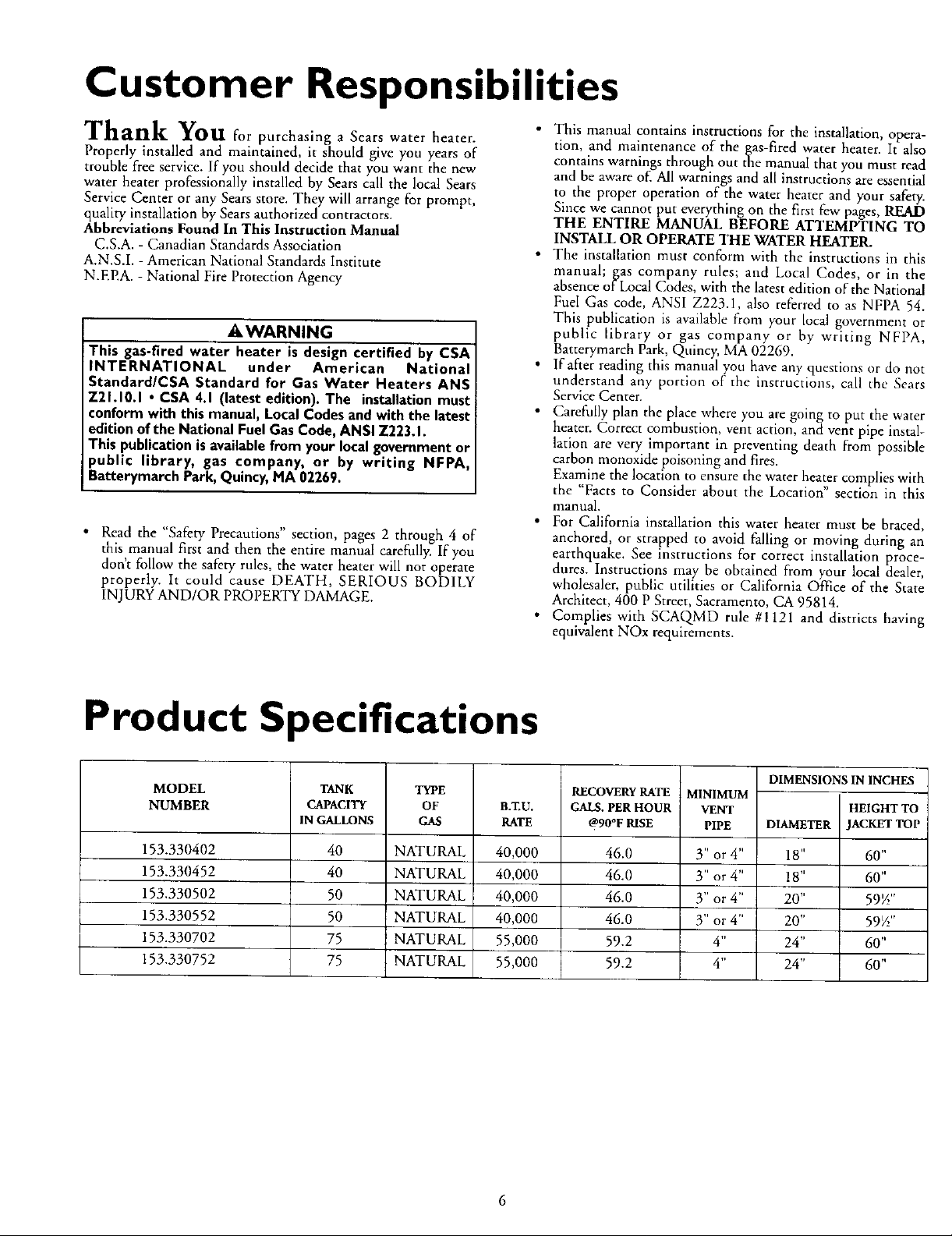
Product Specifications
MODEL
NUMBER
153.330402 40 NATURAL 40,000 46.0 3" or 4"
153.330452 40 NATURAL 40,000 46.0 3" or 4"
153.330502 50 NATURAL 40,000 46.0 Y' or 4"
153.330552 50 NATURAL 40,000 46.0 3" or 4"
153.330702 75 NATURAL 55,000 59.2 4"
153.330752 75 NATURAL 55,000 59.2 4"
TANK
CAPACITY
IN GALLONS
TYPE
OF
GAS
B.T,U.
RATE
RECOVERY RATE
GALS. PER HOUR
@90°F RISE
MINIMUM
VENT
PIPE
DIMENSIONSIN INCHES
HEIGHTTO
DIAMETER JACKETTOP i
18" 60"
18" 60"
20" 59_"
20" 59_"
24" 60"
24" 60"
7
I
Page 7
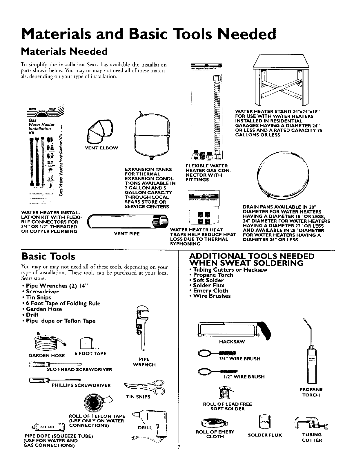
Materials and Basic Tools Needed
Materials Needed
To simplify, the installation Sears has available the installation
parts shown below. You may or may not need all of these materi-
als, depending on your type of installation.
Gas
Water Heater
Installation
Kit
@
VENT ELBOW
i
WATER HEATER STAND 24"x24"x 18"
FOR USE WITH WATER HEATERS
INSTALLED IN RESIDENTIAL
GARAGES HAVING A DIAMETER 24"
OR LESS AND A RATED CAPACITY 75
GALLONS OR LESS
EXPANSION TANKS
FOR THERMAL
EXPANSION CONDI-
TIONS AVAILABLE IN
2 GALLON AND 5
GALLON CAPACITY
THROUGH LOCAL
SEARS STORE OR
SERVICE CENTERS
WATER HEATER INSTAL-
LATION KIT WITH FLEXI-
BLE CONNECTORS FOR
3/4" OR 112" THREADED
OR COPPER PLUMBING
( _
VENT PIPE
Basic Tools
You may or may not need all of these tools, depending on your
type of installation. These tools can be purchased at your local
Sears Store.
• Pipe Wrenches (2) 14"
• Screwdriver
• Tin Snips
• 6 Foot Tape of Folding Rule
• Garden Hose
• Drill
• Pipe dope or Teflon Tape
FLEXIBLE WATER
HEATER GASCON-
NECTORWITH
FITTINGS
WATER HEATER HEAT
TRAPS HELP REDUCE HEAT
LOSS DUE TO THERMAL
SYPHONING
ADDITIONAL TOOLS NEEDED
WHEN SWEAT SOLDERING
• Tubing Cutters or Hacksaw
• Propane Torch
• Soft_Solder
• Solder Flux
• EmeryCIoth
• Wire Brushes
DRAIN PANS AVAILABLE tN 20"
DIAMETER FOR WATER HEATERS
HAVING A DIAMETER 18" OR LESS,
24" DIAMETER FOR WATER HEATERS
HAVING A DIAMETER 22" OR LESS
AND AVAILABLE IN 28" DIAMETER
FOR WATER HEATERS HAVING A
DIAMETER 26" OR LESS
GARDEN HOSE 6 FOOT TAPE
SLOT-HEAD SCREWDRIVER
PHILLIPS SCREWDRIVER
ROLL OF TEFLON TAPE
(USE ONLY ON WATER
CONNECTIONS)
PIPE DOPE (SQUEEZE TUBE)
(USE FOR WATER AND
GAS CONNECTIONS)
PIPE
WRENCH
TIN SNIPS
HACKSAW
3/4" WIRE BRUSH
I/2" WIRE BRUSH
ROLL OF LEAD FREE
SOFT SOLDER
ROLL OF EMERY
CLOTH SOLDER FLUX TUBING
PROPANE
TORCH
CUTTER
Page 8
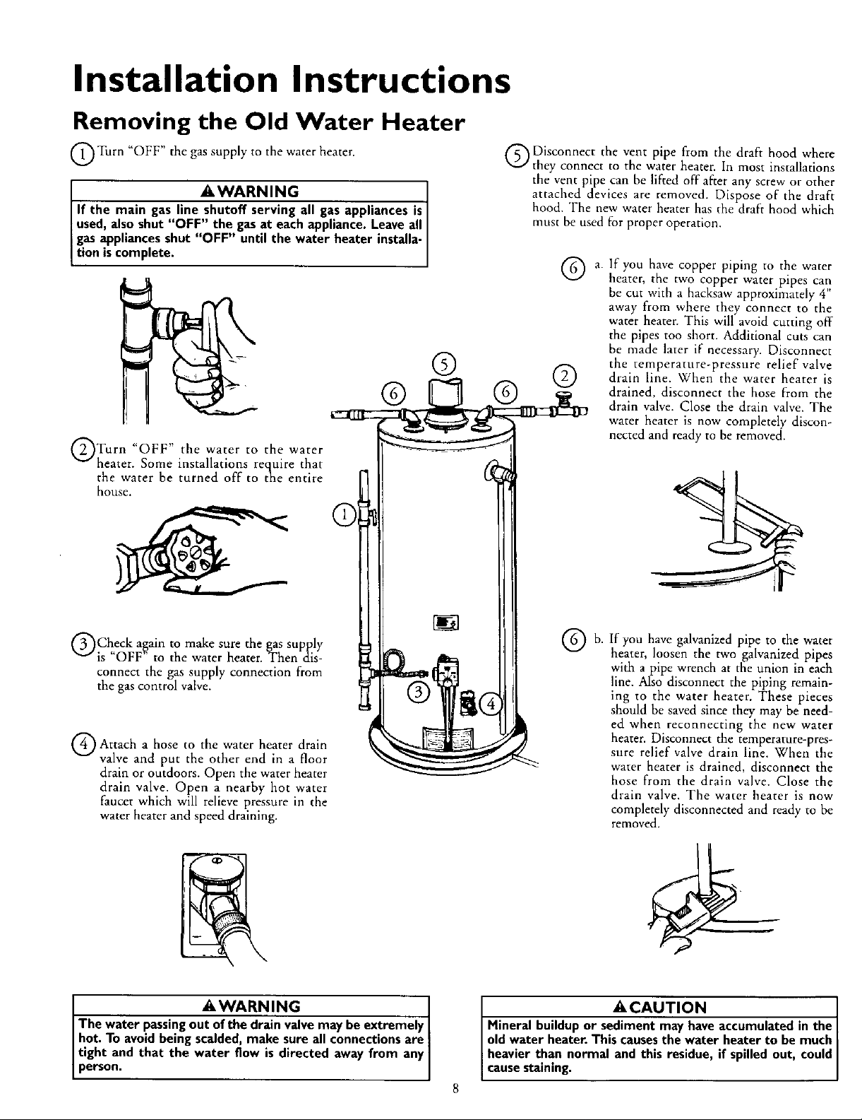
Installation Instructions
Removing the Old Water Heater
Turn "OFF" the gas supply to the water heater.
_,WARNING
If the main gas line shutoff serving all gas appliances is[
used, alsoshut "OFF" the gasat each appliance.Leave all [
gasappliancesshut "OFF" until the water heater installa-
tion iscomplete.
"OFF" the the
Turn water to water
heater. Some installations require that
the water be turned off to the entire
house.
Q Disconnect the vent pipe from the draft hood where
they connect to the water heater. In most installations
the vent pipe can be lifted off"after any screw or other
attached devices are removed. Dispose of the draft
hood. The new water heater has the draft hood which
must be used for proper operation.
Q a. If you have copper piping to the water
® ©
heater, the two copper water pipes can
be cut with a hacksaw approximately 4"
away from where they connect to the
water heater. This will avoid cutting off
the pipes too short. Additional cuts can
be made later if necessary. Disconnect
the temperature-pressure relief valve
drain line. When the water heater is
drained, disconnect the hose from the
drain valve. Close the drain valve. The
water heater is now completely discon-
nected and ready to be removed.
Check again to make sure the gas supply
is "OFF" to the water heater. Then dis-
connect the gas supply connection from
the gas control valve.
Q Attach hose the heater drain
The water passingout of the drain valve may beextremely
hot. To avoidbeing scalded,make sure all connectionsare
tight and that the water flow is directed away from any
person.
a to water
valve and put the other end in a floor
drain or outdoors. Open the water heater
drain valve. Open a nearby hot water
faucet which will relieve pressure in the
water heater and speed draining.
AWARNING [
If
Q b. you galvanized pipe to water
have the
heater, loosen the two galvanized pipes
with a pipe wrench at the union in each
line. Also disconnect the piping remain-
ing to the water heater. These pieces
should be saved since they may be need-
ed when reconnecting the new water
heater. Disconnect the temperature-pres-
sure relief valve drain line. When the
water heater is drained, disconnect the
hose from the drain valve. Close the
drain valve. The water heater is now
completely disconnected and ready to be
removed.
_CAUTION I
Mineral buildupor sediment may haveaccumulatedin the I
oldwater heater.Thiscausesthe water heater to be much [
heavier than normal and this residue, if spilledout, could
causestaining.
Page 9
Installation Instructions (cont'd)
Facts to Consider About the
Location
You should carefully choose an indoor location for the new
water heater, because the placement is a very important consid-
eration for the safety of the occupants in the building and for
the most economical use of the appliance. This water heater is
not for use in mobile homes or outdoor installation.
Whether replacing an old water heater or putting the water
heater in a new location, the following critical points must be
observed.
• The location selected should be indoors as close as practical
to the gas vent or chimney to which the water heater vent is
going to be connected, and as centralized with the water pip-
ing system as possible. The water heater, as all water heaters,
will eventually leak. Do not install without adequate
drainage provisions where water flow will cause damage.
A CAUTION
WATER HEATERSEVENTUALLY LEAK: Installationof the
water heater mustbe accomplishedin sucha mannerthat if
thetank or anyconnectionsshouldleak,theflowofwater will
not causedamageto the structure.For this reason, it isnot
advisableto installthe water heaterin an atticor upperfloor
When suchlocationscannotbe avoided,a suitabledrainpan
shouldbe installedunderthewater heater Drainpansareavail-
ableat your localSearsstore. Sucha drain pan must be not
greaterthan I½ inchesdeelghaveaminimumleng_ andwidth
ofat least2 inchesgreaterthan the water heater dimensions
and must be pipedto an adequatedrain.The pan must not
restrict combustionair flow. Under no circumstancesisthe
manufacturer or Searsto beheld liablefor any water damage
inconnectionwiththis water heater
AWARNING
INSTALLATIONS IN AREAS WHERE FLAMMABLE LIQUIDS
(VAPORS) ARE LIKELY TO BE PRESENT OR STORED
(GARAGES, STORAGE, AND UTILITY AREAS, ETC):
Flammable liquids (such as gasoline, solvents, propane (LP) or
butane, etc.), all of which emit flammable vapors, may be
improperly stored or used in such areas. The gaswater heater
pilot light or main burner can ignite suchvapors. The resulting
flashbackand fire cancausedeath or serious burns to anyone in
the area, aswell asproperty damage.
If installation in suchareas is your only option, then the installa.
tion must be accomplished in a way that the pilot flame and
main burner flame are elevated from the floor at least 18 inches.
While this may reduce the chancesof flammable vaporsfrom
floor spillbeing ignited,gasolineandother flammable substance!
shouldnever be stored or used in the same room or area con.
raining a gaswater heater or other open flame or sparkproduc-
ingappliance.
NOTE: Flammable vapors may be drawn by air currents from
other areasof the structure to the appliance.
AWARNING
Propellants of aerosol spraysand volatile compounds, (clean-
ers, chlorine based chemicals, refrigerants, etc.) in addition to
being highly flammable in many cases,will also change to cor-
rosive hydrochloric acid when exposed to the combustion :
products of the water heater. The results can be hazardous,
and also cause product failure.
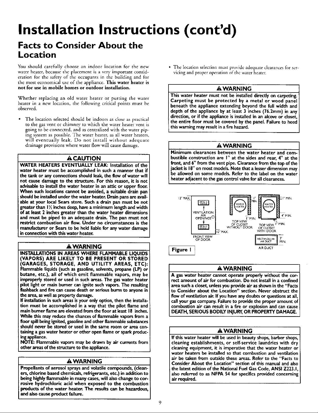
• The location selection must provide adequate clearances for ser-
vicing and proper operation o_'the water heater.
AWARNING
This water heater must not be installed directly on carpeting.
Carpeting must be protected by a metal or wood panel
beneath the appliance extending beyond the full width and
depth of the appliance by at least 3 inches (76.2mm) in any
direction, or if the appliance is installed in an alcove or closet,
the entire floor must be covered by the panel. Failure to heed
this warning may result in afire hazard.
AWARNING
Minimum clearances between the water heater and com-
bustible construction are I" at the sides and rear, 4" at the
front, and 6" from the vent pipe. Clearance from the top of the
jacket is 18"on most models. Note that a lesserdimension may
be allowed on some models. Refer to the label on the water
heater adjacent to the gascontrol valvefor all clearances.
12" MAX
VENTILATION
AIR
OPENINGS O
FRONT VIDN
OF DOOR
TOP VIEW , i
OF CLOSET TOP VIEW I" MIN.
WITHOUT DOOR OF CLOSET
12' MAX WiTH DOOR
R"N
'1!' MIN _=_a _4"M_N"
AIR DUCT
Figure I ]
AWARNING
A gaswater heater cannot operate properly without the cor-
rect amount of air for combustion. Do not install in a confined
area sucha closet, unlessyou provideair asshown in the "Facts
to Consider about the Location" section. Never obstruct the
flow of ventilation air. Ifyou have any doubts or questionsat all,
call your gascompany. Failure to provide the proper amount of
combustion air can result in a fire or explosion and can cause
DEATH, SERIOUS BODILY INJUR_,OR PROPERTY DAMAGE.
AWARNING
If this water heater will be usedin beauty shops,barber shops,
cleaning establishments, or self-service laundries with dry
cleaning equipment, it is imperative that the water heater or
water heaters be installed sothat combustion and ventilation
air be taken from outside these areas. Refer to the "Facts to
Consider About the Location" section of this manual and also
the latest edition of the National FuelGas Code, ANSI Z223.1,
also referred to as NFPA 54 for specificsprovided concerning
air required.
9
3,,
Page 10

Installation Instructions (cont'd)
Combustion Air and Ventilation
for Appliances Located in
Unconfined Spaces
Unconfined Space is a space whose volume is not less than 50
cubic feet per 1,000 Btu per hour of the aggregate input rating
of all appliances installed in that space. Rooms communicating
directly with the space in which the appliances are installed,
through openings nor furnished with doors, are considered a
part of the unconfined space
In unconfined spaces in buildings, infiltration may be adequate
to provide air for combustion, ventilation and dilution of flue
gases. However, in buildings of tight construction (for example,
weather stripping, heavily insulated, caulked, vapor barrier, etc.),
additional air may need to be provided using the methods
described in Combustion Air and Ventilation for Appliances
Located in Confined Spaces, b.
Combustion Air and Ventilation
for Appliances Located in
Confined Spaces
Confined Space is a space whose volume is less than 50 cubic
feet per 1,000 Btu per hour of the aggregate input rating of all
appliances installed in that space.
a. ALL AIR FROM INSIDE BUILDINGS:
(See Page 9 Figure 1, and Figure 2 below)
The confined space shall be provided with two permanent
openings communicating directly with an additional room(s)
of sufficient volume so that the combined volume of all
spaces meets the criteria for an unconfined space. The total
input of all _as utilization equipment installed in the com-
bined space snail be considered in making this determination.
Each opening shall have a minimum free area Of one square
inch per 1,000 BTU per hour of the total input rating of all
gas utilization equipment in the confined space, but not less
than 100 square inches. One opening shall commence within
12" of the top and one commencing within 12" of the bot-
tom of the enclosure.
1. When directly communicating with the outdoors, each open-
ing shall have a minimum free area of 1 square inch per 4,000
BTU per hour of total input rating of all equipment in the
enclosure. (See Figure 3.)
2. When communicating with the outdoors through vertical
ducts, each opening shall have a minimum free area of 1
square inch per 4,000 BTU per hour of total input rating of
all equipment in the enclosure. (See Figure 4.)
3. When communicating with the outdoors through horizontal
ducts, each opening shall have a minimum free area of 1
square inch per 2,000 BTU per hour of total input rating of
all equipment in the enclosure. (See Figure 5.)
ENT
Figure 2 ]
b. ALL AIR FROM OUTDOORS: (see Figures 3-5)
The confined space shall be provided with two permanent
openings, one commencing within 12" of the top and one
commencing within 12" from the bottom of the enclosure.
The openings shall communicate directly, or by ducts, with
the outdoors or spaces (crawl or attic) that freely communi-
cate with the outdoors.
Figure 3 ]
Figure 5 ]
4. When ducts are used, they shall be of the same cross-sectional
area as the free area of the openings to which they connect.
The minimum short side dimension of rectangular air ducts
shall not be less than 3". (See Figure 5.)
5.
Louvers and Grilles: In calculating free area, consideration
shall be given to the blocking effect of louvers, grilles or
screens protecting openings. Screens used shall not be smaller
than ¼" mesh. If the free area through a design of louver or
grille is known, it should be used in calculating the size open-
ing required to provide the free area specified. If the design
and free area is not known, it may be assumed that wood lou-
vers will be 20-25 percent free area and metal louvers and
grilles will have 60-75 percent free area. Louvers and grilles
shall be fixed in the open position or interlocked with the
equipment so that they are opened automatically during
equipment operation.
6.
Special Conditions Created by Mechanical Exhausting or
Fireplaces: Operation of exhaust fans, ventilation systems,
clothes dryers or fireplaces may create conditions requiring
special attention to avoid unsatisfactory operation of installed
10
gas utilization equipment.
......... i
4
Page 11

Installation Instructions (cont'd)
Water Piping
AWARNING
HOTTER WATER CAN SCALD: Water heatersare intendedto
produce hot water. Water heated to a temperature which will
satisfyclothes washing, dish washing,and other sanitizingneeds
can scaldand permanently injure you upon contact. Some peo-
ple are more likelyto be permanently injured byhot water than
other_ These includethe elderly,children,the infirm, or physical-
ly/mentally handicapped.If anyone usinghot water in your home
fits into one of thesegroupsor if there isa localcodeor state law
roquiHng a certain temperature water at the hot water tap,then
you must take specialprecautions. In addition to usingthe lowest
possibletemperature setting that satisfiesyour hot water needs,
a meanssuchas a mixing valve, shouldbe usedat the hot water
taps used by these people or at the water heater. Mixingvalves
are availableat plumbingsupplyor hardware stores.Follow man-
ufacturers instructions for installation of the valves. Before
changing the factory setting on the thermostat, read the
"Temperature Regulation" sectionin thismanual.
This water heater shallnot be connected to any heating systems or
component(s) used with a non-potable water heating appliance.
If a water heater is installed in a closed water supply system;
such as one having a back-flow preventer, check valve, water
meter with a check valve, etc.., in the cold water supply; means
shall be provided to control thermal expansion. Contact the
local utility or local Sears Service Center on how to control this
situation.
Look at the top cover of the water heater. The cold water
inlet is marked cold. Put two or three turns of teflon tape
around the threaded end of the threaded-to-sweat coupling
and around both ends of the _" threaded nipple. Using flexi-
ble connectors, connect the cold water pipe to the coldwater
inlet of the water heater.
NOTE: This water heater is super insulated to minimize
heat loss from the tank. Further reduction in heat loss
can be accomplished by insulating the hot water lines
from the water heater.
INSTALLATION COMPLETED USING
SEARS INSTALLATION KIT
HOT OUTLET
TO HOUSE
_IIE--
FLEXIBLE WATER
CONNECTORS
/
THREADED TO
SWEAT COUPLING
THREADED TO
SWEAT COUPLING
COLD INLET
WATER LINE
NOTE: Toprotect against untimely corrosion of hot and
cold water fittings, it is strongly recommended that di-elec-
tric unions or couplings be installed on this water heater
when connected to copper pipe.
The illustration shows the attachment of the water piping to the
water heater. The water heater is equipped with + "
nections.
water Con-
NOTE.' If using copper tubing, solder tubing to an adapter
before attaching the adapter to the cold water inlet connec-
tion. Do not solder the cold water supply line directly to the
cold water inlet. It will harm the dip tube and damage the
tank.
• Look at the top cover of the water heater. The water outlet is
marked hot. Put two or three turns of teflon tape around the
threaded end of the threaded-to-sweat coupling and around
both ends of the _+' threaded nipple. Using flexible connec-
tors, connect the hot water pipe to the hot water outlet on
the water heater.
314"THREADED
HEAT TRAP WITH
SECONDARY
ANODE
-- 314" THREADED
HEAT TRAP
--TEMPERATURE-
PRESSURE
RELIEFVALVE
-- DISCHARGE
PIPE (Do not
capor plug)
--6" AIR GAP
11
FLOOR DRAIN
Page 12

Installation Instructions (cont'd)
Temperature-Pressure Relief Valve
AWARNING
At the time of manufacture this water heater was provided
with a combination temperature-pressures relief valve certified
by a nationally recognized testing laboratory that maintain
)eriodic inspection of production of listed equipment or mate-
rials, as meeting the requirements for Relief Valves and
Automatic GasShutoff Devicesfor Hot Water Supply Systems,
and the latest edition of ANSI Z21.22 and the code require-
ments of ASME. If replaced, the valve must meet the require-
ments of local codes, but not lessthan a combination tempera-
ture and pressure relief valve certified as meeting the require-
ments for Relief Valves and Automatic Gas Shutoff Devicesfor
Hot Water Supply Systems, ANSI Z21.22 by a nationally recog-
nized testing laboratory that maintains periodic inspection of
production of listedequipment or materials.
The valve must be marked with a maximum set pressure not
to exceed the marked hydrostatic working pressure of thq
water heater (150 Ibs./sq. in.) and a discharge capacity not less
than the water heater input rate as shown on the model rating
plate. (Electric heaters - watts divided by 1000 x 3415 equal
BTU/Hr. rate.)
Your local jurisdictional authority, while mandating the useof a
temperature-pressure relief valve complying with ANSI Z21.22
and ASME, may require a valve model different from the one
furnishedwith the water heater.
Compliance with such local requirements must be satisfied by
the installer or end user of the water heater with a locally pre-
scribed temperature-pressure relief valve installed in the desig-
nated opening in the water heater in place of the factory fur-
nishedvalve.
For safe operation of the water heater, the relief valve must not
be removed from it'sdesignatedopening or plugged.
The temperature-pressure relief valve must be installed directly
into the fitting of the water heater designatedfor the relief valve.
Positionthe valve downward and providetubing so that any dis-
charge will exit only within 6 inchesabove, or at any distance
below the structural floor. Be certain that no contact is made
with any liveelectrical part. The dischargeopening must not be
blocked or reduced in size under any circumstances. Excessive
length, over 30 feet, or use of more than four elbows can cause
restriction and reduce the dischargecapacityof the valve.
No valveor other obstruction isto be placed between the relief
valve and the tank. Do not connect tubing directly to discharge
drain unlessa 6" air gapis provided.To prevent bodilyinjury, haz-
ard to life, or property damage,the relief valve must be allowed
to dischargewater in quantities shouldcircumstancesdemand. If
the discharge pipe is not connected to a drain or other suitable
means,the water flow may causeproperty damage.
The Discharge Pipe:
Must not be smaller in size than the outlet pipe size of the
valve, or have any reducing couplingsor other restrictions.
Must not be plugged or blocked.
Must be of material listedfor hot water distribution.
Must be installed so as to allow complete drainage of both
the temperature-pressure relief valve, and the discharge
pipe.
Must terminate at an adequate drain.
Must not haveany valvebetween the relief valveand tank.
AWARNING
The temperature-pressure relief valve must be manually
operated at least once a year. Caution should be taken to
ensure that (I) no one is in front of or around the outlet of
the temperature-pressure relief valve discharge line, and (2)
the water manually discharged will not cause any bodily
injury or property damage because the water may be
extremely hot.
If after manually operating the valve, it fails to completely
reset and continues to release water, immediately close the
cold water inlet to the water heater, follow the draining
instructions, and replace the temperature-pressure relief
valve with a new one.
HOT
SHUT OFF
VALVE
PIPE (Do not cap
)_
FLOOR DRAIN
COLD
PRESSURE
RELIEF VALVE
or plug)
GAP
RELIEFVALVEOPENING
At the time of manufacture, this water heater was provided with a combinationtem-
perature-pressure relief valve listed as complying with the standard for relief valves
and automatic gas shut-off devices for hot water supply systems, ANSI Z21.22. For
safeoperation of the water heatec the relief valve must not be removed from its des-
ignatedpoint of installation or plugged.
Your local iurisdictional authority, while mandating the use of a temperature-pressure
relief valve complying with ANSI Z21.22 and ASME,may require a valve model differ-
ent from the one furnished with the water heater
Compliance with such local requirementsmust besatisfied by the installer or end user
of the water heater with a locally prescribed temperature-pressure relief valve
installed in the designated opening in the water heate_
See manual heading -"Temperature-PressureRelief Valves"for installationand mainte-
nance of relief valve,discharge line, and other safety precauuons
]2
Page 13

Installation Instructions (cont'd)
Filling the Water Heater
A CAUTION J
Never use this water heater unless it is completely filled with J
water. To prevent damage to the tank, the tank must be fiUed J
with water. Water must flow from the hot water faucet
before turn ng ON gas to the water heater.
To fill the water heater with water:
• Close the water heater drain valve by turning the handle to
the right (clockwise). The drain valve is on the lower front of
the water heater.
• Open the cold water supply valve to the water heater.
NOTE: The cold water supply valve must be left open
when the water heater is in use.
• To insure complete filling of the tank, allow air to exit by
opening the nearest hot water faucet. Allow water to run
until a constant flow is obtained. This will let air out of the
water heater and the piping.
• Check all new water piping for leaks. Repair as needed.
Venting
AWARNING
VENT DAMPERS - Any vent damper, whether it is operated
thermally or otherwise must be removed ifits useinhibits prop-
er drafting ofthe water heater.
Thermally Operated Vent Dampers: Gas-fired water heaters
havingthermal efficiency in excessof 80% may produce a rela.
tivelylowflue gastemperature. Suchtemperatures may not be
high enough to properly open thermally operated vent
dampers. This would causespillage of flue gasesand maycause
carbonmonoxide poisoning,
Vent dampers must bear evidence of certification ascomplying
with the latest edition of American National Standard ANSI
Z21.68 (ANSI Z21.66 & 67, respectively, cover electrically and
mechanically actuated vent dampers). Before installation of any
vent damper, consult your local SearsService Center or the gas
utility for further information.
AWARNING
To insure proper venting of this gas-fired water heater, the
correct vent pipe diameter must be utilized. Any additions or
deletions of other gasappliances on a common vent with this
water heater may adversely affect the operation of the water
heater. Consult the local Sears Service Center or gas utility if
any such changes are planned.
For proper venting in certain installations, a larger diameter vent
pipe may be necessary. Due to great variances in installations,
unforeseeable by the manufacturer of the water heater, you must
consult your gas company to aid you in determining the proper
venting for your water heater from the vent tables in the latest
edition of the National Fuel Gas Code ANSI Z223.1, also
referred to as NFPA 54.
Check the venting system for signs of obstruction or deteriora-
tion and replace if needed.
The combustion and ventilation air flow must not be obstructed.
AWARNING J
Obstructedor deterioratedventsystemsmaypresentaserious
healthHskor asphyxat on.
Place the draft hood legs in the receiving holes on the top of
the water heater. The legs will snap in the holes to give a tight
fit.
• Place the vent pipe over the draft hood. With the vent pipe in
position, drill a small hole through both the vent pipe and
draft hood. Secure them together with a sheet metal screw.
DRAFT HOOD '_? VENTxJ !
, _L _ &f__- SCREVV___J DRAFT HOOD
VENT TO OUTDOORS OR
DRAFT HO_ IMNEY
AWARNING J
The water heater with draft hood installed must be properly J
vented to a chimney which terminates outdoors. Never oper- J
ate the water heater unlessit is vented to the outdoors and hasJ
adequate air supplyto avoidHsksof improper operation, explo-
sionor asphyxiation.
AWARNING
The vent pipe from the water heater must be no lessthan the
diameter of the draft hood outlet on the water heater, and
must slope upward to the chimney at least ¼inch per linear
foot.
13
Page 14

Installation Instructions (cont'd)
Venting (cont'd)
All vent gases must be completely vented to the outdoors of the
structure (dwelling). install only the draft hood provided with
the new water heater and no other draft hood.
Vent pipes must be secured at each joint with sheet metal screws.
TO
CHIMNEY
!
VENT PIPE INSTALLATION
There must be a minimum of 6" clearance between single wall
vent pipe and any combustible material. Fill and seal any clear-
ance between single wall vent pipe and combustible material
with mortar mix, cement, or other noncombustible substance.
For other than single wall, follow vent pipe manufacturer's clear-
ance specifications. To insure a tight fit of the vent pipe in a
brick chimney, seal around the vent pipe with mortar mix
cement.
AWARNING
Failureto haverequired clearancesbetweenventpipingand
combustiblematerial will result in afirehazard.
Gas Piping
AWARNING
Makesure the gassuppliedisthe sametype listedon the
model rating plate. The inlet gaspressuremust not exceed
10.5in.water column(2.6kPa)for natural gasor 13in. water
column (3.2kPa) for propane (L.P.)gas.The minimum inlet
gaspressurelistedon the model rating plate isfor the pur-
poseofinputadjustment.
AWARNING ,
Ifthe gascontrolvalveis subjectedto pressuresexceeding'A
poundper squareinch(3.5kPa),the damageto the gascon-
trol valvecouldresult ina fireor explosionfrom leakinggas.
_WARNING
If the main gaslineshutoffservingall gasappliancesisused,
alsoturn "OFF" thegasat eachappliance.Leaveallgasappli.
ancesshutoff untilthe water heaterinstallationiscomplete.
A gas line of sufficient size must be run to the water heater.
Consult the latest edition of National Fuel Gas Code ANSI
Z223.1, also referred to as NFPA 54 and the gas company con-
cerning pipe size.
AWARNING ]
Besureventpipe ispropodyconnectedto preventescapeof I
dangerousfluegaseswhichcouldcausedeadlyasphyxiation. ]
AWARNING
Chemical vapor corrosionof the flueand vent systemmay
occurif air for combustioncontainscertainchemicalvapors.
Spraycanpropellants,cleaningsolvents,refrigerator and air
conditionerrefrigerants, swimmingpool chemicals,calcium
and sodiumchloride,waxes,bleach,andprocesschemicalsare
typicalcompoundswhicharepotentiallycorrosive.
There must be:
• A readily accessible manual shut offvalve in the gas supply llne
serving the water heater, and
• A drip leg (sediment trap) ahead of the gas control valve to help
prevent dirt and foreign materials from entering the gas control
valve.
• A flexible gas connector or a ground joint union between the
shutoffvalve and control valve to permit servicing ofthe unit.
Be sure to check all the gas piping for leaks before lil_hting the
water heater. Use a soapy water solution, not a match or open
flame. Rinse offsoapy solution and wipe dry.
Standard Models are for installation up to 3,300 feet above sea
level.
High Altitude Models are for installation from 3,300 to 5,500
feet above sea level.
If a standard model is installed above 3,300 feet or a high altitude
model is installed above 5,500 feet, the input rating must he
reduced at the rate of 4 percent for each 1,000 feet above sea level.
Contact your local Sears Service Center or gas utility for further
information.
f AWARNING
The applianceand it_ must be leak tested
beforeplacingtheapplianceinoperation.
14
Page 15

Installation Instructions (cont'd)
A, WARNING
• The appliance and itsindividualshutoffvalvemust:bediscon-
nectedfromthe gassupplypipingsystemduringany pressure
testingof the gassystemat test pressuresin excessof
poundpersquareinch(3.5kPa).
• The appliancemust beisolatedfromthegassupplypipingsys
tem byclosingits individualmanualshutoffvalveduringany
pressuretestingof the gassupplypipingsystemat test pres-
suresequalorlessthan½poundper squareinch(3.5kPa).
li WARNING
Use pipe joint compound or teflon tape marked as being
resistant to the actionofpetroleum [Propane(L.R)] gases.
SEDIMENT TRAP
A sediment trap shall be installed as close to the inlet of the
water heater as practical at the time of water heater installation.
The sediment trap shall be either a tee fitting with a capped nip-
ple in the bottom outlet or other device recognized as an effec-
tive sediment trap. If a tee fitting is used, it shall be installed in
conformance with one of the methods of installation shown
below.
Connecting the gas piping to the gas control valve of the water
heater can be accomplished by either of the two methods shown,
GAS PIPING WITH
FLEXIBLE CONNECTOR
O,OO OO T
UNlON(Opti_ VE
CAP
GAS PIPING WITH ALL BLACK IRON
PIPE TO GAS CONTROL
GROUND JOINT _ BLACK PIPE
GAS
CONTROL
UNION(Optional) __
VALVE
li WARNING
Contaminantsinthe gaslinesmaycauseimproperoperation
of the gascontrolvalvethat mayresultin Ere or explosion.
Beforeattachingthe gaslinebe surethat allgaspipe isclean
on the inside.To trap any dirt or foreign material in the gas
supplyline, a drip leg (sometimes called a sedimenttrap)
must be incorporated in the piping.The drip legmust be
readily accessible.Installinaccordancewith the "Gas Piping"
section.Referto the latesteditionof the National Fuel Gas
Code,ANSI Z223.1,alsoreferred to asNFPA 54.
15
Page 16

Installation Instructions (cont'd)
Installation Checklist
BEFORE LIGHTING THE PILOT:
• Check the gas lines for leaks•
a. Use a soapy water solution. DO NOT test for gas leaks
usinga match or open flame.
b. Brush the soapy water solution on all gas pipes, joints and
fittings.
c. Check for bubbling soap. This means you have a leak.
urn OFF gas andmake the necessary repalrs.
d. Recheck for leaks.
e. Rinse off soapy solution and wipe dry.
VENT PIPE TO
OR CHIMNEY
HOT
• Is the new temperature-pressure relief valve properly installed
and piped to an adequate drain? See "Temperature-Pressure
Relief Valve" section.
• Are the cold and hot water lines connected to the water
heater correctly? See "Water Piping" instructions in the
"Installation Instructions" section•
OUTDOORS
UNION SHUTOFF VALVE
..€ COLD
DRAFT
HOOD
TEMPERATURE-
PRESSURE
RELIEFVALVE
• Is the water heater completely filled with water? See "Filling"
instructions in the "Installation Instructions".
• Will a water leak damage anything? See the "Facts to
Consider About the Location" section.
• Is there proper clearance between the water heater and any-
thing that might catch fire? See the "Facts to Consider About
" the Location" section.
• Do you have adequate ventilation so that the water heater
will operate properly? See "Combustion Air and Ventilation"
m the Facts to Conmder About the gocatmn section.
• Is the draft hood vent piping properly secured? See "Venting"
instructions in the "Installation Instructions" section.
• Is there proper clearance between the vent pipe and anything
that m'ght catch on fire? See Venting" instructions in the
"Installation Instruct'ons' section•
• Is the vent pipe properly sloped and does the vent terminate
outdoors? See "Venting" instructions in the "Installation
Instructions" section.
• Do you need to call your gas company to check the gas pipe
and its hookup?
CHECK FOR LEAKS
Be sure to check all your gas pipes for leaks before lighting your
water heater. Use a soapy water solution, not a match or open
flame. Check the factory gas fittings after pilot is lit and gas con-
trol knob is still in "PILOT" position. Then, check the fittings
when the main burner is turned "ON". Use a soapy water solu-
tion for this, too.
SHUTOFF
VALVE
DRIP LEG
(SEDIMENT
TRAP)
GAS SUPPLY
TEE
PIPE CAP
1 DISCHARGE PIPE
(Do not capor plug)
(under cover)
,!iI
"I
FLOOR DRAIN
I I WATER HEATER
us cw.
MAYJ.MU M h_OSTAT_ _ PRESSURE IN W C
_'Sl wc WC wc
MODEL RATING PLATE
I 1 I
NCH AIR GAP
16
Page 17

Operating Instructions
Lighting
ilWARNING
BEFORE LIGHTING PROPANE (LR) GAS WATER HEATERS:
Propane (L.R) gas is heavier than air. Should there be a leak in
the system, the gas will settle near the ground. Basements,
crawl spaces, skirted areas under mobile homes (even when
ventilated), closets and areas below ground level will serveas
pockets for the accumulation of this gas. Before attempting to
light or rolight the water heater's pilot or turning on a nearby
electrical light switch, be absolutely sure there isno accumulat-
ecl gasin the area. Search for odor of gas by sniffing at ground
level in the vicinity of the appliance. If odor is detected, follow
steps indicated at "For Your Safety" on the cover page of this
manual then leavethe premises.
Lighting and operating instructions are located on front of the
water heater, above or to one side of the gas control valve.
iI WARNING
AN ODORANT IS ADDED TO THE GAS USED
BY THIS WATER HEATER.
FOR YOUR SAFETY
IF YOU SHELL GAS:
Do not try to light any appliance.
Do not touch any electrical switch; do not use any phone in
your building.
Immediately call your gassupplier from a neighbor's phone.
Follow the gassuppliers instructions.
If you cannot reach your gas supplier, call the fire
department.
I Figure 6 ]
Figure 7 ]
A, WARNING
DO NOT force the gas control knob. Use only your hand to i
push it down to light the pilot, or to turn it to "ON", "OFF"
or "PILOT". Never use a tool such as a lever, wrench or pli-
ers. Do not hit or damage the knob. A damaged knob may
result in an explosion and serious injury. If you have problem
turning the knob, call the gassupplier immediately.
Figure 8 ]
OUTER DOOR
17
Figure 9]
Page 18

Operating Instructions (cont'd)
Lighting label on the water heater as it appears above the thermostat
FOR YOUR SAFETY READ BEFORE LIGHTINI
WARNING
If you do not follow these instructions exactly, a fire or explosion
may resu t caus ng property damage, personal injury or loss of life.
A. This appliancehasa pilotwhichmustbe lightedby
hand.Whenlightingthe pilot,followthese instructions
exactly.
B. BEFORELIGHTINGsmellall aroundtheappliancearea
for gas. Be sureto smellnextto the floor because
somegasisheavierthanairandwillsettleonthefloor.
WHATTODOIFYOUSMELLGAS
• Donottry to lightanyappliance.
• Do not touch any electric switch; do notuse any
phoneinyourbuilding.
• Immediatelycall yourgassupplierfroma neighbor's
phone.Followthegassupplier'sinstructions.
LIGHTING INSTRUCTIONS
• If you cannotreachyour gas supplier,callthe fire
department.
C. Use onlyyourhandto pushin orturnthegas control
knob.Neverusetools.If the knobwillnot pushin or
turnbyhand,don'ttryto repairit,call aqualifiedser-
vicetechnician,Forceor attemptedrepairmayresult
inafireorexplosion,
D.Do not usethis applianceif any part has beenunder
water.Immediatelycall a qualifiedservicetechnician
to inspectthe applianceandto replaceanypartofthe
controlsystemandany gascontrolwhichhasbeen
underwater.
1.STOP!Readthesafetyinformationaboveonthislabel.
2. Removeouterdoor.
3. Setthe thermostatto lowest setting byturning the
watertemperaturedial clockwise,(( _,)to itslowest
temperaturesetting(witharrowon dial)asshown.DO
NOT FORCE.
4.Turngas controlknobclockwise_'V _ to "OFF" posi-
tion. Knob cannotbe turned from "PILOT" to "OFF"
unlessknob is depressedslightly.DO NOT FORCE.
(Figure6, page17)
5. Waitfive (5) minutesto clearoutany gas.If youthen
smellgas,STOP!Follow"B" in the safetyinformation
aboveon this label. If you don't smellgas, go to the
nextstep.
6. Remove(oropen) inner door located belowthe gas
controlunit.
7.Findpilot-followmetaltube THERMOCOUPLEI'l!, PILOTBURNER
fromgascontrol.Thepilot _F__.,.
islocatedinfront oftheburner. -
8.If youdon'tsmellgas,turnknobon gascontrolcounter
clockwiseL,@ to "PILOT"position.(Figure7,page17)
9. Push in control knob all the way and hold down.
Immediatelylightthepilotwitha match.Continueto
hold controlknob in for aboutone (f) minuteafter
thepilot islit. Releaseknoband itwill pop backup.
Pilotshouldremainlit. If it goesout, repeatsteps3
through8.
• If knobdoesnot pop upwhenreleased,stopand
immediatelycall your servicetechnicianor gas
supplier.
• If the pilot will not stay lit after severaltries,
depressandturn the gascontrolknobclockwise
_'_ to "OFF"andcallyourservicetechnician
orgassupplier.(Figure6,page17)
10. Replace(orclose)innerdoor.Replaceouterdoor if
doordoesnot covergascontrolon/offknobor tem-
peratureadjustmentknob.(Figure9, page17)
11. Atarmslenqthaway,turn gascontro knobcounter-
clockwise_ to thefull "ON" position.Warning
do not use gas control knob to regulate gas
flow. (Figure8,page17)
12. At armslengthaway,set the thermostatto desired
setting. The mark ( • ) indicative of approximate
120°F is preferredstarting point. Somelocal laws
mayrequirea lowerstartingpoint.If hotterwateris
desired,seeinstructionmanualand"warning" below.
13.Replacetheouterdoorifnotreplacedinstep10.
WARNING
Hotterwater increasesthe riskof scald injury,Before changingtemperaturesettingsee instructionmanual.
TO TURN OFF GAS TO APPLIANCE
1.Set thethermostatto lowest settingby turningthe
watertemperaturedialclockwise(F_) to its lowest
temperaturesetting(witharrowon dial)asshown.DO
NOT FORCE.
2. Turngas control knob clockwise _t
position.Knob cannotbe turned from "PILOT" to
"OFF" unlessknob is depressedslightly.DO NOT
FORCE.
3. Replaceouterdoor(ifremoved).
]8
to
"OFF"
Page 19

Operating Instructions (cont'd)
Temperature Regulation
Due to the nature of the typical gas water heater, the water tern- Turn the water temperature dial clockwi_["_) to decrease
perature in certain situations may vary up to 30°F higher or the temperature, or counterclockwise (€" "_) to increase the
lower at the point of use such as, bathtubs, showers, sink, etc. temperature.
This means that when the temperature adjustment dial is set at
the mark approximating 120°E the actual water temperature at
any hot water tap could be as high as 150°F or as low as90°E
Any water heater's intended purpose is to heat water. Hot water
is needed for cleaning (bodies, dishes, clothing). Hot water will
present a scald hazard. Depending on the time element, and the
people involved (normal adults, children, toddlers, elderly,
infirm, etc.) scalding may occur at different temperatures.
_i,WARNING
HOTTERWATERCAN SCALD:Water heatersareintendedto
producehot water Water heatedto a temperaturewhichwill
satisfyclotheswashing,dishwashing,andother sanitizingneeds
canscaldandpermanentlyinjureyouupon contact.Somepeo-
plearemorelikelyto be permanentlyinjuredbyhotwater than
others.Theseincludethe elderly,children,the infirm,orphysical.
ly/mentallyhandicapped.Ifanyoneusinghotwaterinyourhome
fitsintooneofthesegroupsor ifthere isa localcodeor statelaw
requiringa certaintemperature waterat thehotwater tap,then
youmusttakespecialprecautions.Inadditiontousingthe lowest
mssibletemperaturesettingthatsatisfiesyour hotwater needs,
a meanssuchas a mixingvalve,shouldbeusedat the hotwater
tapsused bythese peopleor at the waterheater.Mixingvalves
areavailableatplumbingsupplyor hardwarestores.Followman-
ufacturersinstructionsfor installationof the valves.Before
changingthe factory setting on the thermostat, read the
"TemperatureRegulation"sectioninthismanual.
PILOT
LIGHTING - Set here before lighting pilot.
• Is a thermostat setting of approximately
120°F, which will supply hot water at the
most economical temperatures. The tempera-
ture adjustment knob can be turned lower
than 120°F if&sired.
A- Is a thermostat setting of approximately
130°E
B - Is a thermostat setting of approximately
I40°E
AWARNING
Never allow smallchildrento usea hot water tap, or to draw
their ownbathwater. Never leavea childor handicappedper-
sonunattendedina bathtubor shower
The thermostat of this water heater has been factory set at its
lowest position, to reduce the risk of scald injury. It isadjustable
and must be reset to the desired temperature setting. The mark
(A) indicative of approximately 120°F is the preferred starting
point. Some states have a requirement for a lower setting, lfyou
need hotter water, follow directions for temperature adjustment,
but beware of the warnings in this section.
C - Is a thermostat setting of approximately
150°E
VERY HOT -Is a thermostat setting of 160°E It is recom-
mended that the dial be set lower whenever
possible.
NOTE: Water temperature range of 120°--140°F recom-
mended by most dishwasher manufacturers.
AWARNING
Shouldoverheatingoccur or the gassupplyfail to shutoff,
turn "OFF" the manualgascontrolvalvetothe appliance.
19
Page 20

Service and Adjustment
Tank (Sediment) Cleaning
Sediment build-up on the tank bottom may create varying
amounts of noise, and if left in the tank will cause premature
tank failure. In some water areas, you may not be able to drain
all sediment deposits by simply draining the tank. In these cases
Mag Erad (part no. 23600) can be used to help remove the sedi-
ment deposits. This may be ordered from the Sears Service
Center. For ordering, refer to the "Parts Order List" section.
Venting System Inspection
At least once a year a visual inspection should be made of the
venting system. You should look for:
Obstructions which could cause improper venting. The com-
bustion and ventilation air flow must not be obstructed.
Damage or deterioration which could cause improper vent-
ing orleakage of combustion products.
Rusted flakes around top of water heater.
AWARNING
Chemical vapor corrosion of the flue and vent system may
occur if air for combustion contains certain chemical vapors.
Spray can propellants, cleaning solvents, refrigerator and air
conditioner refrigerants, swimming pool chemicals, calcium
and sodium chloride, waxes, bleach, and processchemicals are
typical compounds which are potentially corrosive.
Burner Inspection
I AWARNING ]
Do not usethisapplianceifanypartof it hasbeenunderwater/
Immediately call a SearsService Technicianto inspectthe/
applianceandto replace the gascontrol or any part of the/
burnersystemwhichhasbeenunderwater, ]
At least once a year a visual inspection should be made of the
main burner and pilot burner. The drawing is for your reference.
You should check for sooting which is not normal and will
impair proper combustion.
AWARNING
Soot build-up indicates a problem that requires correction
before further use. Turn "OFF" gasto water heater and leave
"OFF" until repairs are made, because failure to correct the
cause of the sooting can result in a fire or explosion causing
DEATH, SERIOUS BODILY INJURY, OR PROPERTY
DAMAGE.
AWARNING
Obstructed or deteriorated vent systemsmay present a serious
health risk or asphyxiation.
AWARNING --_
Be sure the vent piping is properly connected to prevent I
escape of dangerous flue gasses which could cause deadly I
asphyxiation. /
AWARNING ]
If after inspection of the vent system you found sooting or/
deterioration, something iswrong. Call the local gasutility to|
correct the problem and clean or replace the flue and venting|
before resuming operation of the water heater, |
Burner Cleaning
In the event your burner needs cleaning, use the following
instructions:
If inspection of the burner shows that cleaning is required, turn
the gas control knob clockwise (f'-_) to the "OFF" osition,
depressing slightly.
NOTE: The knob cannot be turned from "PILOT" to "OFF"
unless knob is depressed slighdy. DO NOT FORCE.
Loose deposits on or around the burner can be removed by care-
fully using the hose of a vacuum cleaner inserted through the
access door of the water heater. If the burner needs to be removed
for additional cleaning, call the Sears Service Center to remove
and clean the burner and correct the problem that required the
burner to be cleaned.
P
2O
Page 21

Service and Adjustment (cont'd)
Draining
The water heater should be drained if being shut down during
freezing temperatures. Also periodic draining and cleaning of
sediment from the tank may be necessary.
Turn the gas control knob to the "OFF" position.
CLOSE the cold water inlet valve to the water heater.
OPEN a nearby hot water faucet and leave open to allow for
draining.
Connect a hose to the drain valve and terminate to an
adequate drain.
OPEN the water heater drain valve to allow for tank
draining.
NOTE: If the water heater is going to be shut down and
drained for an extended period, the drain valve should be
left open with hose connected allowing water to terminate
to an adequate drain.
Close the drain valve.
Follow instructions in the "Filling The Water Heater"
section.
Follow the lighting instructions in the "Lighting" section to
restart the water heater.
Temperature-Pressure Relief
Valve Operation
The temperature-pressure relief valve must be manually operated
at least once a year.
TEMPERATURE-PRESSURE
REL_VALVE
AWARNING
When checking the temperature-pressure relief valve opera-
tion, make sure that (I) no one is in front of or around the
outlet of the temperature-pressure relief valve discharge line,
and (2) that the water manually dischargedwill not cause any
property damage because the water may be extremely hot.
If after manually operating the valve, it falls to completely
reset and continues to release water, immediately close the
cold water inlet to the water heater, follow the draining
instructions, and replace the temperature-pressure relief
valve with a new one.
Drain Valve Washer
Replacement
NOTE: For replacement, use a _Y_2"x _/_" x _" thick washer
available at your nearest hardware store. For ordering replace-
ment washers, refer to the "Parts Order List"section.
Turn "OFF" gas supply to water heater.
Follow "Draining" instructions.
Turning counter clockwise, remove the hex cap below the
screw handle.
Remove the washer and put the new one in place.
Screw the handle and cap assembly back into the drain valve
and retighten using awrench. DO NOT OVER TIGHTEN.
Follow instructions in the "Filling The Water Heater"
section.
Check for leaks.
Follow the lighting instructions in the "Lighting" section to
restart the water heater.
DISCHARGE PIPE
Failure to install and maintain a new properly listed tempera-
ture-pressure relief valve will release the manufacturer from any
claim which might result from excessive temperature or pressure.
AWARNING
If the temperature-pressure relief valve on the appliance
weeps or dischargesperiodically, this may be due to thermal
expansion. Your water heater may have a check valve
installed in the water line or a water meter with a check
valve. Consult the Sears Service Center for further informa-
tion. Do not plugthe temperature-pressure relief valve.
_AND CAP
ASSEMBLY
WASHER
Housekeeping
Vacuum around base of water heater for dust, dirt, and lint on a
regular basis.
Combustible materials such as clothing, cleaning materials, or
flammable liquids, etc. must not be placed against or adjacent to
the water heater.
To insure sufficient ventilation and combustion air supply, prop-
er clearances from the water heater must be maintained at all
times.
Service
Before calling for repair servicc, read the Start Up Conditions
and Operational Conditions found in the Troubleshooting
Guide of this manual
If a condition persists or you are uncertain about the operation
of the water heater, let a qualified person check it out.
Contact SEARS Repair Services at 1-800-4-MY-HOME
(1-800-469-4663).
21
Page 22

Troubleshooting Guide
Start Up Conditions
CONDENSATION
Whenever the water heater is filled with cold water, a certain
amount of condensation will form while the burner is on. A
water heater may appear to be leaking when in fact the water is
condensation. This usually happens when:
• When a new water heater is filled with cold water for the
first time.
• When gas burns and water vapor is produced in water
heaters, particularly high efficiency models where flue ten>
peratures are lower.
• When you use large amounts of hot water in a short time
and the refill water is very cold.
Moisture front the products of combustion condense on the
cooler tank surfaces and form drops of water which may fall
onto the burner or other hot surfaces to produce a "sizzling" or
"frying" noise.
Excessive condensation can cause pilot outage due to water run-
ning down the flue tube onto the main burner and putting out
the pilot.
Because of the suddenness and amount of water, condensation
water may be diagnosed as a "tank leak". After the water in the
tank warms up (about 1-2 hours), the condition should
disappear.
Do not assume the water heater is leaking until there has been
enough time for the water in the tank to warm up.
An undersized water heater will cause more condensation. The
water heater must he sized properly to meet the family's
demands for hot water including dishwashers, washing machines
and shower heads.
SMOKE/ODOR
It is not uncommon to experience a small amount of smoke and
odor during the inltia[ start-up. This is due to burning off ofoil
from metal parts, and wilt disappear in a short while.
THERMAL EXPANSION
Water supply systems may, because of high line pressttre, fie-
quent cut-offs, the eft_cts of water hammer and others, have
installed devices such as pressure reducing valves, check valves,
back flow preventers, etc. to control these types of problems.
When these devices are not equipped with an internal by-pass,
and no other measures are taken, the devices cause the water sys-
tem to be closed. As water is heated, it expands (thernta[ expan-
sion) and closed systems do not allow for the expansion of heat-
ed water.
The water within the water heater tank expands as it is heated
and increases the pressure of the water system. If the relieving
point of the water heater's temperature-pressure relief valve is
reached, the valve will relieve the excess pressure. The tempera-
ture_ressure relief valve is not intended for the constant
relier of thermal expansion. This is an unacceptable condition
and must be corrected.
It is recommended that any devices insta ed wh ch could create
a closed system have aby-pass and/or the system have an expan-
sion tank to relieve the pressure built by thermal expansion in
the water system. Expansion tanks are available for ordering
through the Sears Service Center. Contact the local plumbing
inspector, water supplier, and/or the Sears Service Center for
assistance in controlling these situations.
Excessive condensation may be noticed during the winter and
early spring months when incoming water temperatures are at
their lowest.
Good venting is essential for a gas fired water heater to operate
properly as well as to carry away products of combustion and
water vapor.
AWARNING
HOTTERWATERCAN SCALD:Water heatersare intendedto
producehot water.Water heatedto a temperaturewhichwill
satisfyclotheswashing,dishwashing,andothersanitizingneeds
canscaldandpermanentlyinjureyouuponcontact.Somepeo-
plearemore likelyto be permanentlyinjuredbyhotwater than
others.Theseincludethe elderly,children,theinfirm,orphysical-
lylmeotallyhandicapped.If anyoneusinghotwaterinyour home
fitsintooneoftbesegroupsor ifthereisalocalcodeor statelaw
requiringacertaintemperaturewaterat thehotwatertap,then
youmusttakespecialprecautions.Inadditionto usingthelowest
possibletemperaturesettingthat satisfiesyourhotwater needs,
a meanssuchasa mixingvalve,shouldbeusedatthe hotwater
tapsusedbythesepeopleor at the water heater.Mixingvalves
areavailableatplumbingsupplyor hardwarestores.Followman-
ufacturersinstructionsfor installationof the valves.Before
changingthe factory setting on the thermostat, read the
"TemperatureRegulation"sectioninthis manual.
Thermal Expansion Tank Specifications
Model Tank Capacity Dimensions in Inches Pipe Fitting
Number In Gallons Diameter Length On Tank
153.331020 2 8 inches '12_ inches _" Male
153.331050 5 11 inches ' 14_ inches _," Male
Expansion Tank Sizing Chart
Inlet* Water Heater Capacity (Gallons)
Water
Expansion Pressure 30 40 50 66 82
Tank 40psi 2 2 2 5 5
Capacity 50psi 2 2 ' 2 5 5
Needed 60psl 2 2 5 5 5
70psi 2 2 5 5 5
80psi 2 5 5 5 5
*Highest recorded inlet water pressure in a 24 hour period or
regulated water presstne.
NOTE: Expansion tanks are pro-charged with a 40 psi air
charge. If the inlet water pressure is higher than 40 psi, the
expansion tank's air pressure must be adjusted to match that
pressure, but must not be higher than 80 psi.
22
Page 23

Troubleshooting Guide (cont'd)
Operational Conditions
HOT COLD WATERHEATER (3)
WATER HEATER
COLD WATER
INLET FITTING
HOT
COLDWATER PRESSURE
INLETFITTING REDUCING
EXPA(I)SIO N _'_
TANK __
PRESSUREGAUGE INLETCOLD
RECOMMENDED INSTALLATION
(VERTICAL MOUNTING)
FLOOR, CEILING
STRAPPING
(,)
EXPANSION
VALVEWITH
BY-PASS
JOIST,ETC.
(3)
PRESSURE
REDUCING INLETCOLD
VALVEWITH WATER
BY-PASS SHUTOFF
WATER
SHUTOFF
SMELLY WATER
in each glasslined water heater there is installed at least one
anode rod (see parts section) for corrosion protection of the
tank. Certain water conditions will cause a reaction between this
rod and the water. The most common complaint associated with
the anode rod is one of a "rotten egg smell". This odor is derived
from hydrogen sulfide gas dissolved in the water. The smell is
the restllt of four factors which must all be present for the odor
to develop:
a. a concentration of sulfate in the supply water.
b. little or no dissolved oxygen in the water.
c. a sulfate reducing bacteria within the water heater. (This
harmless bacteria isnon-toxic to humans.)
d. an excess of active hydrogen in the tank. This is caused by
the corrosion protective action of the anode.
Smelly water may be eliminated or reduced in some water heater
models by replacingthe anode(s) with one of lessactive material,
and then chlorinating the water heater tank and all hot water
lines. Contact Sears Service for further information concerning
an Anode Replacement Kit #9001453 and this Chlorination
Treatment.
If the smelly water persists after the anode replacement and chlo-
rination treatment, we can only suggest that continuous chlori-
nation and filtering conditioning equipment he considered to
eliminate the water problem.
Do not remove the anode leaving the tank unprotected. By
doing so, all warranty on the water heater tank is voided.
"AIR" IN HOT WATER FAUCETS
PRESSUREGAUGE
ALTERNATE RECOMMENDED
INSTALLATION
(HORIZONTAL MOUNTING)
STRANGE SOUNDS
Possible noises due to expansion and contraction of some metal
parts during periods of heat-up and cool-down do not represent
harmful or dangerous conditions.
Condensation causes sizzling and popping with the burner area
during beating and coolln{_ periods and should be considered
normal. See Condensation section.
AWARNING
HYDROGEN GAS: Hydrogen gas can be produced in a hot
water system that hasnot been used for a long period of time
(generally two weeks or more). Hydrogen gas is extremely
flammable and explosive. To prevent the possibility of injury
under these conditions, we recommend the hot water faucet
be opened for several minutes at the kitchen sink before any
electrical appliances which are connected to the hot water sys-
tem are used (such as a dishwasher or washing machine). If
hydrogen gas is present, there will probably be an unusual
soundsimilar to air escapingthrough the pipeas the hot water
faucet is opened. There must be no smoking or open flame
near the faucet at the time it isopen.
23
Page 24

Troubleshooting Guide (cont'd)
Operational Conditions (cont'd)
HIGH TEMPERATURE SHUT OFF SYSTEM WATER IS TOO HOT
This water heater is equipped with an automatic gas shut offsys-
tern. The high temperature shut off is built into the gas control
valve. This system shuts off the gas supply to the water heater
burners when high water temperatures ate present. It is non-
resettable. If the high temperature shut off activates, the gas con-
trol valve must be replaced. If this were to occur, turn "OFF" the
entire gas supply to the water heater. Contact the Sears Service
CeNter.
AWARNING
Shouldoverheating o_upply fail to shut off,
turn "OFF" the manualgascontrolvalve to the appliance.
NOT ENOUGH OR NO HOT WATER
• Check the manual gas shut off valve to be sure it is open.
• Check the pilot flame. It may have gone out. All models have
an opening behind the outer door for viewing the pilot.
• If the pilot is not lit, follow the "Lighting" instructions in this
manual or located above the gas control valve on the water
heater to relight the pilot. If the water was extremely hot and is
now cold, the high limit safety temperature shut off may have
put out the burner and pilot. If the high temperature shut off
activates, the gas control valve must be replaced. Contact the
Sears Service Center.
• The temperature adjustment dial may be set too high. See the
"Temperature Adjustment" section.
NOTE: A period of time is necessary after an adjustment
has been made for the water temperature to reach the new
temperature setting.
• If lower temperature settings will not lower the water tempera-
ture, call the Sears Service Center.
AWARNING
Due to the nature of the typical gas water heater, the
water temperature in certain situations may be hotter
than the thermostat setting.
Short, frequent draws of hot water - especially with very
cold incoming water - can shock the thermostat into brief
operation resulting in hotter and hotter layers of water
closer to the top of the tank.
Changes in hot water usage patterns or raising the tem-
perature differential between the cut-on of the thermo-
stat and the cold water temperature will usually eliminate
the problem.
• The gas control knob must be turned to the "ON" position.
• The temperature adjustment dial may be set too low. See the
"Temperature Regulation" section.
• The gas company can check the gas input to see if it is correct.
An underfired water heater will not heat water as quickly.
• Look for leaking or open hot water faucets. Make sure all are
closed.
• The cold water inlet temperature may be colder during the
winter months. It will take longer to heat the water and seem
like lesshot water.
• If you cannot find what is wrong, call the Sears Service Center.
24
Page 25

Troubleshooting Guide (cont'd)
Leakage Checkpoints
Use this guide to check a "Leaking" water heater. Many suspect-
ed "Leakers"are not leaking tanks. Often the source of the water
can be found and corrected.
If you are not thoroughly familiar with your local gas codes,
your water heater, and safety practices, contact the Sears Service
Center to check the water heater.
Read this manual first. Then before checking the water
heater make sure the gas supply has been turned
"OFF", and never turn the gas "ON" before the tank is
comp ete y fu of water.
Never use this water heater unless it is completely filled
with water. To prevent damage to the tank, the tank
must be filled with water. Water must flow from the hot
water faucet before turning "ON" gas to the water
heater.
ACAUTION i
ACAUTION
O Water at the draft hood is water which has
condensed out of the combustion products. This is caused
by a problem in the vent. Contact the Sears Service Center.
O "Condensation may be seen on pipes in humid weather or
pipe connections may, be leaking.
*The primary anode rod fitting may be leaking.
Small amounts of water from the temperature-pressure
relief valve may be due to thermal expansion or high
water pressure in your area.
o'The temperature-pressure relief valve may be leaking at
the tank fitting.
Q Water from a drain valve may be due to the valve opened
slightly.
O'The drain valve may be leaking at the tank fitting.
Combustion products contain water vapor which can
condense on the cooler surfaces of the tank. Droplets
form and drip into the fire or run on the floor. This is
common at the time ofstartup after installation and when
incoming water is cold.
Water in the water heater bottom or on the floor may be
0
from condensation, loose connections, or the relief valve.
DO NOT replace the water heater until a full inspection
of all possible water sources is made and necessary
corrective steps taken. Leakage from other appliances,
water lines, or ground seepage should also be checked.
vapor
25
NOTE: To check where threaded portion enters tank,
insert cotton swab between jacket opening and fitting.
If cotton is wet, follow "Draining" instructions in the
"Service and Adjustment" section and then remove
fitting. Put pipe dope or teflon tape on the threads
and replace. Then follow "Filling the Water Heater"
instructions in the "Installation Instructions" section.
Page 26

Parts Order List
POWER MISER TM 12 GAS WATER HEATERS
MODEL NUMBERS:
153.330402
153.330452
153.330502
153.330552
153.330702
153.330752
40 Gal. High Altitude
40 Gal.
50 Gal. High Altitude
50 Gal.
75 Gal. High Altitude
75 Gal
2O
2
18
19
i
5
1l
7
12
10W
26
Page 27

Parts Order List (cont'd)
POWER MISERTM 12 GAS WATER HEATERS
MODEL NUMBERS:
153.330402
153.330452
153.330502
153.330552
153.330702
153.330752
NO. PART DESCRIPTION
1 Temperature-Pressure Rdief Valve
2 Primary Anode P.od
3 Cold Inlet Nipple (Heat Trap)
4 Drain Valve
5 Drain Valve Washer
('_2" x Md' x X" thick)**
6 Model Rating Plate
7 Pilot
8 Thermocouple*
9 Pilot Tubing w/Fittings
10 Burner Orifice
(Drill Size)
11 Manifold
12 Burner
13 Manifold Cover
14 Inner Door
15 Gas Control Valve
16 Temperature Adjustment Knob
17 Restrictor Ring
18 Dip Tube
19 Flue Baffle
20 Draft Hood
21 Secondary Anode Rod and
Hot Outlet Nipple (Heat Trap)
Manual
#
#
Mag-Erad
40 Gal. High Altitude
40 Gal.
50 Gal. High Altitude
50 Gal.
75 Gal. High Altitude
75 Gal
153.330402 I 153.330452 153.330702 153.330752KEY
9000071 9000071
9000734 9000734
9000948 9000948
9000254 9000254
9001584 9001584
0270118 0270118
9000285 9000285
4_223390O 4233900
9000278 9000278
0230141 0230120
#36 (HA) #33
9002615 9002615
9002411 9002411
9002494 9002494
9000281 9000281
F145-1277 F145-1277
F145-1280 F145-1280
9001208 9001208
9002444 9002444
9000944 9000944
9000273 9000273
9001792 9001792
ModdNumbem
153.330502 153.330552
PART NUMBERS
9000071 9000071
9000734 9000734
9000948 9000948
9000254 9000254
9001584 9001584
0270118 0270118
9000285 9000285
4233900 4233900
9000278 9000278
0230141 0230120
#36 (HA) #33
9002617 9002617
9002411 9002411
9002494 9002494
9000281 9000281
F145-1277 F145-1277
F145-1280 F145-1280
9001208 9001208
9002443 9002443
9000945 9000945
9000273 9000273
9001792 9001792
0002916640
23600
9000071
9000734
9000948
9000254
9001584
0270118
9000285
4233900
9000278
0230160
#31(HA)
9002621
9002411
9002494
9000281
F145-1277
F145-1280
9000297
9002444
9001452
9000274
9001792 9001792
9OOOO71
9000734
9000948
9000254
9001584
0270118
9000285
4233900
9000278
0230144
#29
9002621
9002411
9002494
9000281
F145-1277
F145-1280
9000297
9002444
9001452
9000274
* These parts are also available at most Sears retail stores.
**Also available at most hardware stores.
tReplaced only on return of damaged plate.
Now that you have purchased your Gas Water Heater, should a need ever exist for repair parts or service, simply contact any SEARS Service
Center or call 1-800-4-MY-HOME (1-800-469-4663) Be sure to provide pertinent facts when you call or visit.
All parts listed may be ordered from any SEARS Service (:enter, most SEARS stores and by calling 1-800-366-PART (1-800-366-7247). If the
parts you need are not stocked locally, your order will be electronically transnfitted to a SEARS Repair Parts Distribution Center for handling
The model number of your Gas Watcr Heater will be fimnd on the mode[ rating plate located near the gas control valve.
WI|EN ORDI",I_,IN(; REPAIR PAP,TS, ALWAYS GIVE THE
FOI.LOWING IN FOI_,MATION:
MODEl. NUMBER PART DESCRIPTION
PART NUMBI'R NAME OF ITEM.
THIS IS A REPAIR PARTS LIST, NOT A PACKING LIST
27
Page 28

Warranty
About Your Warranty
THE PRICE OF YOUR WATER HEATER DOES NOT INCLUDE
A FREE CHECKUP SERVICE CALL. On Water Heater Installations
Arranged BySears, Sears warrants the installation.
ON INSTALLATIONS NOT MADE BY SEARS AUTHORIZED
CONTRACTORS:
1. Your Sears warranty applies to the product only.
2. Sears does not warrant the installation.
3. A charge will be made on service calls due to poor or incomplete
installation. These include:
FULl. ONE YEAR WARRANTY ON WATER HEATER
For one year from the date of purchase, when your Sears Kenmore water heater is installed and operated in a single-flamily residence in
accordance with the instructions in this manual, Sears will:
1. Repair defects in material or workmanship in this water heater, free of charge.
2. Furnish and install a new current model water hearer of equal capacity and quality, free of charge, ira leak occurs in the tank.
LIMITED WARRANTY ON TANKS THAT LEAK
After one year and through 12 years from the date of purchasefor water heaters used in a single-family residence, ifa leak occurs in the
tank, Sears will furnish a new current model water hearer of equal capacity and quality. You will be charged for any installation.
LIMITED WARRANTY ON PARTS
a. Adjusting thermostat.
b. Lighting pilot.
c. Leaks in pipes or fittings.
d. Improper venting
e. Condensation
This manual is in non-technical language. It may help you avoid the
cost of a needless service call. Many service calls really aren't needed.
Such as when:
1. The gas is turned "OFF".
2. The pilot isout.
3. A gas or water leak is due to loose pipe or connections.
After one year and through 12 years from the date of purchase, when your Sears Kenmore water heater is used in a single-family residence
and is installed and operated in accordance with the information in this manual, ifa part flailsdue to a materials or workmanship, Sears
will furnish a replacement freeof charge. You will be charged for labor.
If the water heater issubjected to commercial, institutional, industrial or use in residences of two families or more, the above warranty
coverage for tanks that leak is effective for 2 years from the date of purchase and the above parts warranty is effective for 1 year from the
date of purchase.
To obtain warranty service, SIMPLY CALL 1-800-4MY-HOME (1-800-469-4663). "This warranty appliesonly while this product is in
use in the United States."
This warranty gives you specific legal rights and you may also have other rights which vary from state to state.
SEARS, ROEBUCK AND CO., Dept. 817 WA, HOFFMAN ESTATES, IL 60179
Sears Installation Warranty
In addition to any warranty extended to you on the Sears merchandise
involved, which warranty becomes effective the date the merchandise is
installed should the workmanship of any Sears arranged installation
prove faulty within one year, Sears will, upon notice from you, cause
such faults to be corrected at no additional cost to you. If you want this
heater professionally installed by Sears contact your Sears Salesperson.
They will arrange for prompt, quality installation.
Sears Installation Policy
All installationlabor arrangedby Searsshall be performed in a neat,
workmanlikemanner inaccordancewith generallyaccepted trade prac-
tices. Further,all installations shall comply with all local laws, codes
regulationsand ordinances.The customer shallalso be protected,dur-
ing installation, by insurance relating to property damage, Worker's
Compensation and PublicLiability.
If you want this water heater professionallyinstalledby Searscontact
your Salesperson.They will arrange for prompt, quality installationby
Searsauthorized contractors.
Forin-homemajorbrandrepairservice
Cali24hoursa day,7 daysa week
1-800-4-MY-HOME
(1-800469-4663)
The model number of yourwater heater is found on the modelrating plate on the frontof the water heater
04-00 0002916640-0
Sears, Roebuck and Co., Hoffman Estates, IL 60179 U.S.A.
 Loading...