

Page 1
KGnmar^
Owners
Manual
FOR POTABLE WATER
HEATING ONLY
NOT SUITABLE FOR
SPACE HEATING
Model No.
153.321340 30
153.32134! 30
153.321440 40
153.32144! 40
153.321540 50
153.32154! 50
153.321640
153.32164!
153.321840 80
153.32184! 80 Ga!.
Ga!.
Ga!.
Ga!.
Ga!.
Ga!.
Ga!.
66 Ga!.
66 Ga!.
Ga!.
LISTED
Caution:
Read and Follow
All Safety Rules and
Operating Instructions
Before First Use of
This Product.
Save this Manual for Future Reference.
POWER MISER^'^ll
WATTER HEAXER
Safety Instructions
Installation
Operation
EFFICIENCY
FiATiNG
CEPTiFiED
G
READ THE GENERAL SAFETY SECTION BEGINNING ON INSIDE COVER
AND THEN THIS ENTIRE MANUAL BEFORE INSTALLING OR OPERAT
ING THIS WATER HEATER.
ama
GAMA certification applies to all residential electric water heaters with
capacities of 20 to 120 Gallons. Input rating of 12 Kw or less at a voltage
no greater than 250 V.
• Care and Maintenance
• Troubleshooting
• Parts List
Awarning
Sears, Roebuck and Co., Hoffman Estates, IL 60179 U.S.A.
Printed in the U.S.A. 1203 www.sears.com Part No. 184730-000
Page 2

Safety Precautions
AWÂRNING
Improper installation, adjustirient, alteration, service or mainte
nance can cause DEATH, SERIOUS BODILY INJURf, OR PROP
ERTY DAMAGE, Refer to thiis manual for distance or consult
your local Seam Service Center for further information.
AWARNING
At the time of manufacture this water heater was provided with
a combination temperature-pressures relief valve certified by a
nationally recogni^d testing laboratory that maintains periodic
inspection of production of listed equipment or materials, as
meeting the requirements for Relief Wlros and Automatic Gas
Shutoff Devices for Hot Water Supply System^ and the current
edition of ANSI Z2I.22 • CSA 4,4 and the code requirements of
ASME, If replaced, the valve must meet the requirements of
local codes, but not less than a combination temperature and
pressure relief valve certified as meeting the requirements for
Relief Valves and Automatic Gas Shutoff Devices for Hot VWter
Supply Systems, ANSI Z21,22 • CSA 4,4 by a nationally recog
nized testing laboratory that maintains periodic inspection of
production of listed equipment or materials.
The valve must be marked with a maximum set pressure not
to exceed the marked hydrostatic working pressure of the
water heater (150 lbs, p,s,i,) and a dischar^ capacity not less
than the water heater input rate as shown on the mmlel reting
plate, (Electric heaters - watts divided by 1000 x 3412 equal
BTU/Hr. rate,)
Your local jurrsdictional authority, while mandating the u!% of a
temperature-presure relief valve complying with ANSI Z21.22 •
CSA 4,4 and ASME, m^qr require a val^ model different from
the one furnished with the water heater.
Compliance with such local requirements must be satisfied
the installer or end user of the water heater with a locally pre
scribed temperature-pressure relief valve installed in the desig
nated opening in the water heater in place of the factory for^
nished valve.
For safe operation of the water heater, the relief valve must not
be removed from it% designated opening or plug^d.
The temperature-pressure relief valve must be installed directly
into the fitting of the water heater designated for the relief
valve. Position the valve downwanJ and provide tubing so that
any discharge will exit only within $ inches above, or at any dis
tance below the structural floor. Be certain that no contact is
made with any live electrical part. The dischar^ opening must
not be blocked or reduced in size under any circumstances.
Excessive length, over 30 feet, or use of more than four elbows
can cause restriction and reduce the discharge capacity of the
valve.
No valve or other obstruction is to be placed between the relief
valve and the t§nk. Do not connect tubing directly to discharge
drain unless a 6 air ^ is provided. To prevent bodily injury, haz
ard to life, or property dama^, the relief valve must be allowed
to discharge water in quantities should circumstances demand. If
the discharge pipe is not connected to a drain or other suitable
m^ns, the water flow may cause property damage.
The Dischar^ Pipe:
• Must not be smaller in size than the outlet pipe size of the
valve, or have any reducing couplings or other restrictions.
• Must not be plumed or blocked.
* Must be of mat^al listed for hot water distribution,
* Must be installed so as to allow complete draini^ of both the
temperature-pressure relief valve, and the discharge pipe,
* Must terminate at an adequate drain.
• Must not hare any valve betvreen the relief valve and tank.
AWARNING
HAZARD OF ELECTRICAL SHOCK! Before removing any
access panels or servicing the water heater, make sure the
electrical supply to the water heater is turned “OFF”, Failure
to do this could result in DEATH, SERIOUS BODILY INJURT,
OR PROPERTY DAMAGE.
AWARNING
HOTTER WATER CAN SCALD: Water heaters are intended to
produce hot water. Water heated to a temperature which will ^Is-
space heating, clothes washing, dish washing, and other sanitizing
needs can scald and permanently injure you upon contact Some
people are more litely to be permanently injured by hot water than
others. These include the elderly, children, the infirm, or physical
ly/mentaJly handicapped. If anyone using hot water in your home
fits into one of these groups or if there Is a local code or state law
requiring a certain temperature water at the hot water ta(^ then
you must tals special precautions. In addition to using the lowest
possible temperature setting that satisfies your hot water needs, a
means such as a mixing valre, shall be used at the hot water
u^d by these people or at the water heater. Mixing valres are avaik
able at plumbing supply or hardware stores. Follow manufacturers
instructions for installation of the valves. Before changing the facto
ry setting on the therm^taL tiie "Temperature Regulation”
section in this manual.
AWARNING
WATER HEATERS EQUIPPED FOR ONE VOLTAGE ONLY: This
water heater is equipped for one type voltage only. Check the
rating plate near the bottom access panel for the correct volt>
age. DO NOT use this water heater with any voltage other than
the one shown on the model rating plate. Failure to use the eor^
rect voltage can cause problems which can result in DEATH,
SERIOUS BODILY INJURY, OR PROPERTY DAMAGE. If you
have any questions or doubts consult your electric company.
AWARNING
INSULATING JACKETS; When installing an external water
heater insulation jacleet on an electric water heater;
a. DO NOT cover the temperature-pressure relief valve.
b. DO NOT put insulation over the access covers or any
access areas.
c. DO NOT cover or remove operating instructions, and safe
ty related warring labels and materials affixed to the water
heater,
d. DO obtain new warning and instruction labels from Sears
for placement on the jacket directly over the existing labels.
AWARNING
Do not use this appliance if any part of it has been under
water. An electrical short or malfunction could occur. The
water heater should be replaced.
A CAUTION
WATER HEATERS EVENTUALLY LEAK; Installation of the
water heater must be accomplished in such a manner that if
the tank or any connections should leak, the flow of water
will not cause dama^ to the structure. For this reason, it is
not advisable to install the water heater in an attic or upper
floor. When such locations cannot be avoided, a suitable
drain pan should be installed under the water heater. Drain
pans are available at your local Sears Store. Such a drain pan
must be piped to an adequate drein.
Page 3

Table of Contents
Safety Precautions
Table of Contents
Introduction
.......................................
.............................
..............................
Product Specifications.......................
Preparing for the New Installation
Materials and Basic Tools Needed,.
Materials Needed.,
Basic Tools
.........................................................
Installation Instructions,
Removing the Old. Water Heater.............................................
Facts to Consider About the Location
Facts to Consider About the Convertible Lower FJcmcot,
Water Piping.............................................................................
T&P Valve and. Pipe Insulation
Temperature-Pressure Relief Valve
Filling the Water Heater...........................................................
Converting the T-ower FJement,,,,,
Wiring Diagrams......................................................................
Wiring.......................................................................................
Installation Checklist
...
...............................
.....................................
...........................................
.........................................
.................................
,,,,,,,............,,,,,,,,
,,,,,,,
.....
6-15
...........
...........
...........
...........
...........
...........
.........
...10-12
.........
.........
.........
„2
„3
.,4
.4
,5
„5
„5
6
7
7
8
8
9
10
13
14
15
Service and Adjustment..............
Temperature Regulation...........................................................
Thermostats...............................................................................
Thermostat Settings..................................................................
Upper and. Lower Thermostat Adjustment
Temperature-Pressure Relief Valve Operation
Draining....................................................................................
Element Cleaning and Replacement.........................................
Anode Rod Inspection..............................................................
Drain Valve Washer Replacement...........................................
Service
.............................................................
.............................
........................
Troubleshooting Guide,
Start Up Conditions
Thermal pA-pansion
Strange Sounds...............................................
Operational Conditions.....................................
Smelly Water.,.,,,,,,,,,
Air in Hot Water Faucet’s...............................
Rumbling Noise..............................................
High Temperature Shut Off" System
Not F.nough. or No Hot Water
Water is Too Hot
Leakage Checkpoints........................................
..........................................
.......................................
............
,,,,,,,............,,,,,,
.............
.......................
............................................
...16-20
.........
16
.........
16
.........
16
.........
17
.........
17
.........
17
...18-20
.........
20
.........
20
.........
20
...21-24
.........
21
.........
21
.........
21
,...22,23
.........
22
.........
22
.........
22
,...22,23
.........
23
.........
23
.........
24
Parts Order List.
Warranty
..............
...28-31
...........
32
Page 4

Introduction
Thank You for purchasing a Scars water heater.
Properly installed, and maintained, it should give you years of
trouble free service. If you should, decide that you want the new
water heater professionally installed, contact the local Scars
Service Center or any Scars store. They will arrange for prompt,
quality installation by Scars authorfred contractors.
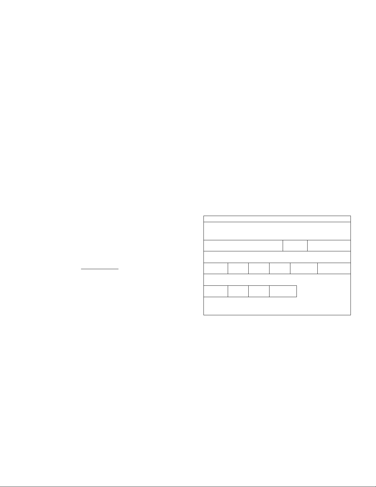
Product Specifications
MODEL
NUMBER
153.321340
153.321341
153.321440
153.321441
153.321540
153.321541
153.321640
153.321641
153.321840
153.321841
TANK
CAPACITY
IK GALLONS
30
40 20 6015,
50
66
80 26
DIMENSIONS IN INCHES
DIAMETER HEIGHT UPPER LOWER
19 47
2215. 62
24 62
62
RECOVERY RATE
GALS. PER HOUR
@ 90“F, RISE
Abbirviatioiis Found In This Instruction ^Manual
U.L. '■ Underwriters laboratories Inc.
NEC - National Electrical Code
ANSI - American National Standards Institute
ELEMENT
WTAGE
AT 240 VOLTS
17.3
25.0 3800 5500 10 30
17.3
25.0 3800 5500 10 30
17.3
25.0 3800 5500 10 30
17.3
25.0 3800 5500 10 30
17.3
25.0 3800 5500 10 30
3800 3800
3800 3800
3800 3800
3800 3800
3800 3800
MINIMUM
WIRE SIZE*
(GAUGE)
12
12
12
12
12
MAXIMUM FUSE
OR CIRCUIT
BREAKER
SIZE (AMPS)
20
20
20
20
20
^Wiring sixe based, on standard bO’C copper wire. If distance from fuse box to water heater is more than 90 feet, refer to your l ocal electri
cal code.
Preparing for the New Installation
Read the “Safety Precautions” section, page 2 of this manual
first and then the entire manual carefully. If you don’t follow
the safety rules, the water heater will not operate properly. It
could cause DEATH, SERIOUS BODILY INJURY
AND/OR PROPERTY DAMAGE,
This manual contains instructions for the installation, opera
tion, and, maintenance of this electric water heater. It also
contains warnings throughout the manual that you must read
and be aware of All warnings and, all instructions arc essen
tial to the proper operation of the water heater and your safe
ty, Since we cannot put everything on the first few pages,
READ THIS ENTIRE MANUAl. BEFORE ATTEMPT
ING TO INSTALL OR OPERATE THE WATER
HEATER.
The installation must conform with the instructions in this
manual; electric company rules; and, Ixical Codes, or in the
absence of Ix)cal Codes, with, the current edition of the NEC
National Electrical Code, NFPA 70, This publication is
available from your local government or public library or
electric company or by writing Underwriters Laboratories
Inc,, 333 Pfingsten Roid, Northbrook, II. 60062,
If after reading this manual you have any questions or d.o not
understand, any portion of foe instructions, call Scars Service
Center,
Carefully plan foe place where you arc going to put foe water
heater. Correct electrical wiring and connections arc very
important in preventing d.cafo. from possible electrical shock
and fires.
Examine the location to ensure the water heater complies with
foe “Facts to Consider About foe Location" section.
For California installation this water heater must be braced,
anchored, or strapped, to avoid falling or moving d.uring an
earthquake. Sec instructions for correct installation proce
dures. Instructions may be obtained from your local dealer,
wholesaler, public utilities or California office of the State
Architect, 400 P Street, Sacramento, CA 95814,
Massachusetts Code requires this water heater to be installed
in accordance with Massachusetts 248-CMR 2,00: State
Plumbing Code and 248-CMR 5,00,
Page 5
Materials and Basic Tools Needed
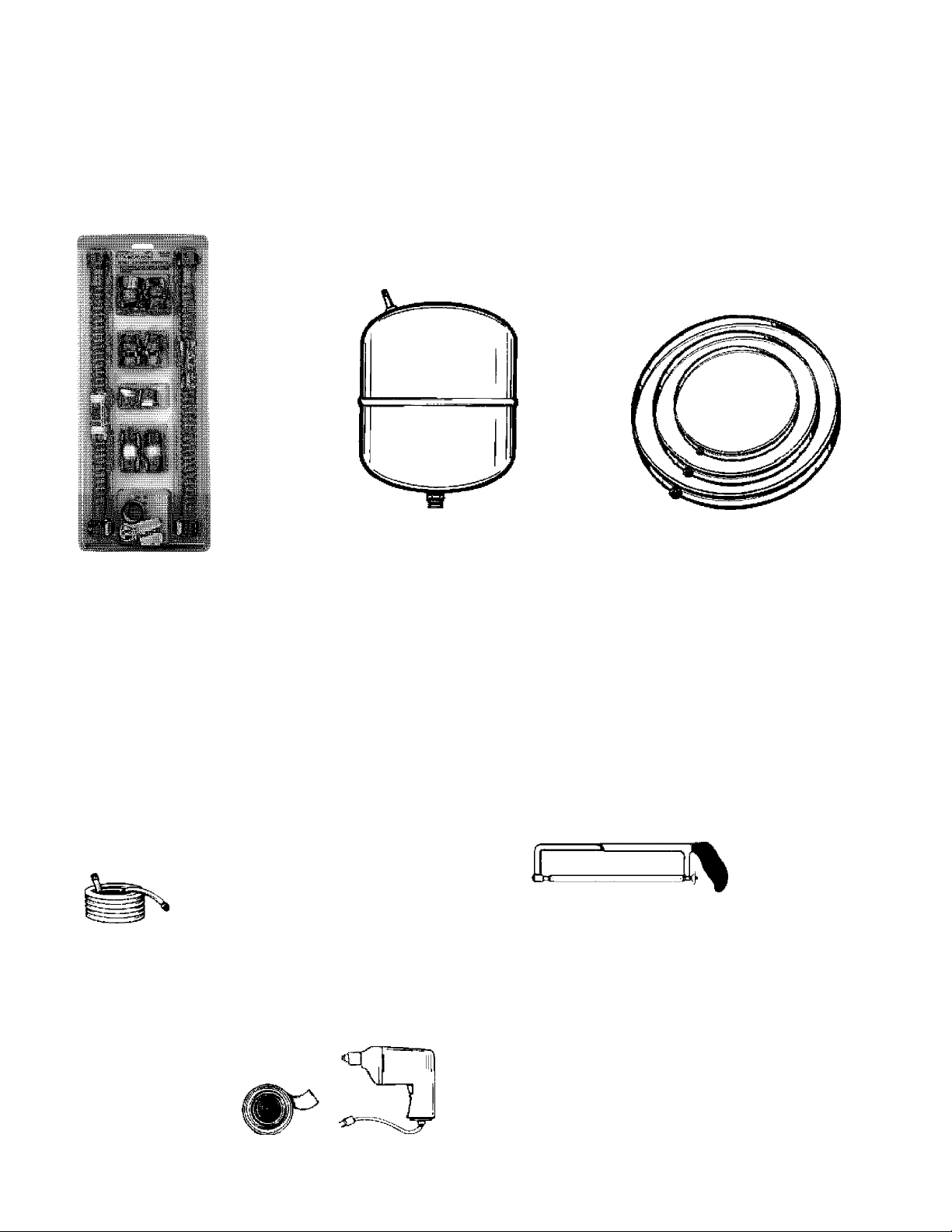
Materials Needed
To simplify the installation Scars has available the installation
parts shown below; You may oi may not need all of these materi
als, depending on your type of installation.
EXPANSION TANI» FOR THERMAL
EXPANSION CONDITIONS AVAILABLE
WATER HEATER INSTALLA
TION KIT WITH FLEXIBLE
CONNECTORS FOR 3/4" OR
1/2" THREADED OR COPPER
PLUMBING
IN 2 GALLON AND 5 GALLON CAPACITY
THROUGH LOCAL SEAF^ STORE OR
SERVICE CENTER
Basle Tools
You may or may not need all of these tools, depending on your
type of installation. These tools can be purchased at youi local
Scars store.
Pipe Wrench (2)
Screwdriver
6 Foot Tape or Folding Rule
Garvlen Hose
Drill
Pipe Dope or Teflon Tape
GARDEN HOSE
SLOT-HEAD SCREW DRIVER
PHILLIPS SCREWDRIVER
8 FOOT TAPE
PIPE
WRENCH
DRAIN PANS AVAILABLE IN 20"
DIAMETER FOR WATER HEATERS
HAVING A DIAMETER 18" OR LESS,
24" DIAMETER FOR WATER
HEATERS HAVING A DIAMETER 22"
OR LESS AND AVAILABLE IN 28”
DIAMETER FOR WATER HEATERS
HAVING A DIAMETER U" OR LESS
ADDITIONAL TOOLS NEEDED
WHEN SWEAT SOLDERING
Tubing Cutters or Hacksaw
Propane Torch
Soft Solder
Solder Flux
Ennery Cloth
Wire Brushes:
HACKSAW
3/4" WIRE BRUSH
1/2" WIRE BRUSH
ñ
*C:
PIPE DOPE
(SQUEEZE TUBE)
(Use only on vmter connections)
ROLL OF TEFLON TAPE DRILL
ROLL OF LEAD FREE
SOFT SOLDER
ROLL OF EMERV
CLOTH
SOLDER
FLUX
PROPANE TORCH
FTÒhì
TUBING
CUTTER
Page 6
Installation Instructions
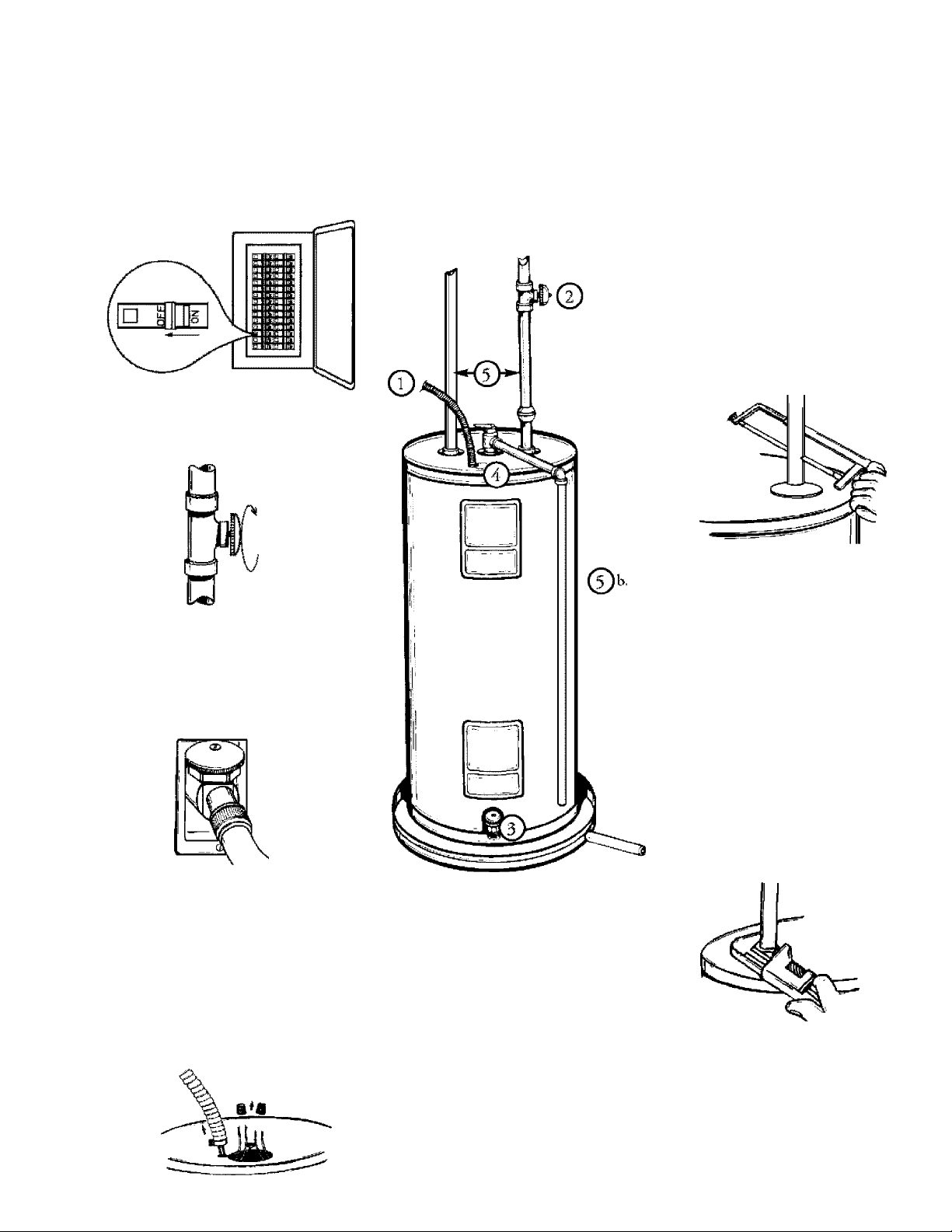
Removing the Old Water Heater
^^Turn “OFF” electrical supply to the water heater.
Turn “OFF” the water supply to the
©
water heater at the water shutoff valve or
water meter.
r^a. If you have copper piping to the water
heater, the two copper water pipes can be
cut with a hacksaw approximately 4" away
from where they connect to the water
heater. This will avoid, cutting off the pipes
too short. Additional cuts can be made
later if necessary. Disconnect the tempera
ture-pressure relief valve drain line, ^Ticn
the water heater is drained,, disconnect the
hose from the drain valve. Close the drain
valve. The water heater is now completely
disconnected and ready to be removed.
Attach a hose to the water heater drain
valve and put the other end, in a floor
drain or outdoors. Open the water heater
drain valve. Open a nearby hot water
faucet which will relieve pressure in the
water heater and speed draining.
AWARNING
The water passing out of the drain valve be extreme
ly hot. To avoid being scalded, make sure all connections
are tight and that the water flow is directed away from
any person.
Check again to make sure the electrical supply is
turned, “OFF” to the water heater. Then disconnect
the electrical supply connection from the water
heater junction box.
If you have galvanixcd, pipe to the water
heater, loosen the two galvanixcd, pipes
with a pipe wrench at the union in each
line. Also disconnect the piping remaining
to the water heater. These pieces should be
saved since they may be needed when
reconnecting the new water heater.
Disconnect the temperature-pressure relief
valve drain line. When the water heater is
drained, disconnect the hose from the
drain valve. Close the drain valve. The
water heater is now completely disconnect
ed and ready to be removed.
A CAUTION
Mineral buildup or sediment may have accumulated in the
old water heater. This causes the water heater to be
much heavier than normal and this residue, if spilled out,
could cause staining.
Page 7
Installation Instructions (cont’d)
Facts to Consider About the Location
You should, carefully choose an indoor location for the new
water heater, because the placement is a very important consid
eration for the safety of the occupants in the building and for
the most economical use of the appliance. This water heater is
not intended for outdoor installation,
'Whether replacing an old water heater or putting the water
heater in a new location, the following critical points must be
observed,
• The location selected should be indoors as close to and as
centralized with the water piping system as possible. This
water heater, as well as all water heaters, will eventually leak.
Do not install without adequate drainage provisions where
water flow will cause damage.
A CAUTION
WATER HEATERS EVENTUALLY LEAK; Installation of
the water heater must be accomplished in such a manner
that if the tank or any connections should leak, the flow of
water will not cause damage to the structure. For this
reason, it is not advisable to install the water heater In an
attic or upper floor. When such locations cannot be ®ioided, a suitable drain pan should be installed under the
water heater. Drain pans are available at your local Sears
stores. Such a drain pan must be piped to an adequate
drain.
Facts to Consider About The
Convertible Lower Element
The Upper Element (if a double element model), is a conven
tional 3800 watt clement which only operates at its rated
wattage on 240 volts, (Sec rating plate on water heater).
The Ixjwcr FJement of the water heater can be converted from
operation at 3800 watts to .5.500 watts on a 240 volt system.
Read and follow water heater warnings and instructions. If after
reading these instructions in this manual, if you do not under
stand any portion, call Scars Service Center.
AWÂRNING
Before making the conversion to SSOO watts, check the
(I) power supply...must be 240 volts, (2) wiring... 10 gauge
AWG, Type TW, 60*C or equivalent, and (3) Circuit
brealffirs or fuslng.„capable of 30 amp loading. Also, the
Installation must conform with this manual, local codes
and electric utility rules. Failure to comply can result in
DEATH, SERIOUS BODILY INJURY, OR PROPERTY
DAMAGE,
«4 ooRfiespowEMce re- xTS. .гиатАМРп
ШУ9 ИВШЮН MOOEL & CUI J
ELECTRIC VWTER HEATER eco
THIS №ATCR AL- /11- Л tHSfiALLtU
MODEL NUMBER СаРАСГГУ
A CAUTION
INSTALLATION IN RESIDENTIAL GARAGES; The
water heater must be located and/or protected so It Is
not subject to physical damage by a moving vehicle.
The location selection must provide adequate clearances for
servicing and proper operation of the wutcr heater.
nguniT Е1.ЕЮГГ MMHUtlU WLTR'-’ : yncLKKJ Fient WQHHHaFnea.pwi
VÏATTS WATTS WATTS . :: IF CONVERTED
^iCTORV equipped WTTH .
150
WATT8 WAT13
3PTIONM.WATTAOE
UROt L0M91
NOTE; Whetlier or not the element, coiivewaott is made the
model rating plate must be marked. Using a bard point ink
pen, check the appropria.te block witbiii the model rating
plate, which is located adjacent to the lower access panel.
WATTS A.C. P INSTALLED
MMiMLiM CHËCKi.'mEBE ’
■' ..fACTOPVEQUIPI
è:::-": WARNINQ
CONVERSЮN
INSTRUCTION
?ED
Page 8
Installation Instructions (cont’d)
Water Piping
WARNING
HOTTER WATER CAN SCALD; Water heaters are
intended ta produce hot water. Water heated to a temper
ature which will satisfy space heating, clothes washing, dish
washing, and other sanitizing needs can scald and perm№
nentfy injure you upon contact Some people are more like
ly to be permanently injured by hot water than others.
These include the elderly, children, the infirm, or physical-
ly/mentalfy handicapped. If anyone using hot water in your
home fits into one of these groups or if there is a local code
or state law requiring a certain temperature water at the
hot water tap, then you must take special precautions. In
addition to using the lowest possible temperature setting
that satisfies your hot water needs, a means such as a mix
ing valve, shall be used at the hot water taps used by these
people or at the water heater, Mbdng valves are available at
plumbing supply or hardware stores. Follow manufacturers
instructions for installation of the valves. Before changing
the factory setting on the thermostat, read the
“Temperature Regulation” section in this manual.
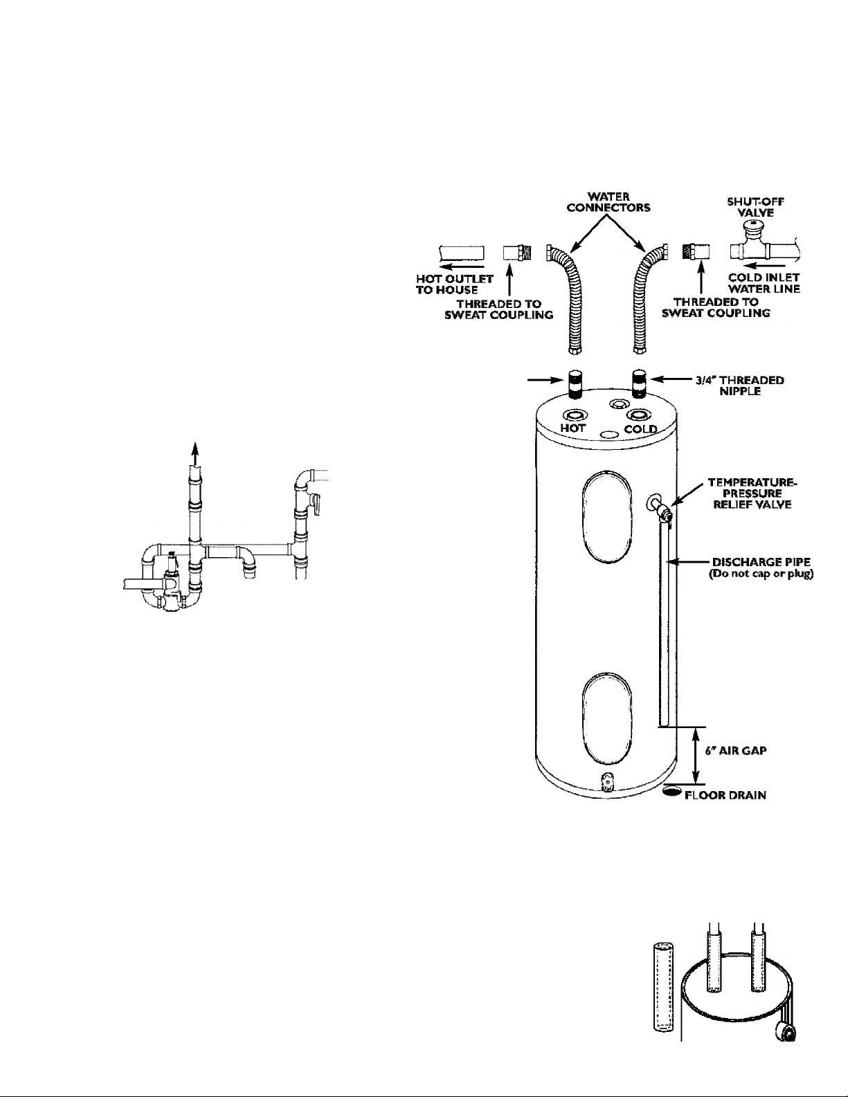
HOT WATER
OUTLET
COLD WATER
INLET
Installation completed using
Installation Kit
3/4* THREADED
NIPPLE
FLEXIBLE
TEMPERED
WATER OUTLET
I
FROM HOT
«MIXING VALVE
The illustrition shows the attachment of the water piping to the vrater
heater. The water heater is equipped with ¥f water connections.
If a water heater is installed in a closed water supply system; such as one
having a back- flow prevxnter, check valve, water meter with a check valve,
etc, in the cold water supply, means shall be provided to contml thermal
expansion, Qsntact the local, utility or local Seara Service Center on how
to control this situation,
NOTE; If osLug copper hibing. solder tubing to an adapter before
attadiiiig tlie ac^t^ to die cold water inlet cotmecdoti. Do not sol
der foe cold water supply line direedy to die cold waiter inlet. It will
liartn foe dip tube and damage die taiik,
• look at the top cover of the water heater. The water outlet is markd
hot. Put two or thiee turns of teflon tape amund the thieaded end of
the threaded-to-sweat coupling and around both ends of the ¥f
threaded nipple. Using flexible connectors, connect the hot water pipe
to the hot water outla of the water heater,
• Look at the top cover of the water heater. The cold water inlet is
marked cold. Put two or three turns of teflon tape amund the threaded
end of the threaded-to-sweat coupling and around both ends of the ¥f
threaded nipple. Using flexible connectors, connect the cold water pipe
to the cold water inlet of the water heater.
NOTE: Your water heater is super insulated to inmimree heat loss
from die tank. Further reduction in heat loss can be accomplished by
iusulatiug foe hot wetter lines from foe heater,
WATER OUTLET
ON WATER HEATER
I TO COLD WATER
Y INLET ON
WATER HEATER
T&P Valve and Pipe Insulation
Remove insulation for T&P Valve and pipe connections from
Fit pipe insulation over foe incoming cold water line and
water line. Make sure that the insula
tion is against the top cover of the
heater.
Fit T&P Valve insulation, over v-alvc.
Malx sure that the insulation docs
not interfere with the lever of the
T6iP valve.
Secure all insulation using tape.
catton.
the hot
Page 9
Installation Instructions (cont’d)
Tempe ratu re- P ressu re
Relief Valve
AWARNING
At the tíme of manufacture this water heater was provided
with a combination temperature-pressures relief valve cer
tified by a nationally recognized testing laboratory that
maintains periodic inspection of production of listed equip
ment or materiaJs, as meeting the requirements for Relief
Valves and Automatic Gas Shutoff Devices for Hot Water
Supply Systems, and the current edition of ANSI Z2I.22 •
CSA 4.4 and the code requirements of ASME. If replaced,
the valve must meet the requirements of local codes, but
not less than a combination temperature and pressure
relief valve certified as meeting the requirements for Relief
Valves and Automatic Gas Shutoff Devices for Hot Water
Supply Systems, ANSI Z21.22 * CSA 4.4 fcy a nationally rec
ognized testing laboratory that maintains periodic inspec
tion of production of listed equipment or materials.
The valve must be marked with a maximum set pressure
not to exceed the marked hydrostatic working pressure of
the water heater (ISO IbsJsq, in,} and a dischai^e capacity
not less than the water heater input rate as shown on the
model rating plate. (Electric heaters - watts divided by
1000 X 3412 equal BTU/Hr. rate.)
Your local jurisdictional authority, while mandating the use
of a temperature-pressure relief valve complying with ANSI
Z21,22 * CSA 4,4 and ASME, may require a valve model dif
ferent from the one furnished with the water heater.
Compliance with such local requirements must be satisfied
by the installer or end user of the water heater with a
locally prescribed temperature-pressure relief valve
installed in the designated opening in the water heater in
place of the factory furnished valve.
For safe operation of the water heater, the relief valve must
not be removed from itis designated opening or plumed.
The temperature-pressure relief valve must be installed
directly into the fitting of the water heater designated for
the relief valve. Position the valve downwat^ and provide
tubing so that an^ discharge will exit only within ¿ inches
above, or at any distance below the structural floor. Be cer
tain that no contact is made with any live electrical part
The discharge opening must not be blocked or reduced in
size under any circumstances. Excessive length, over 30
feet, or use of more than four elbows can cause restriction
and reduce the discharge capacity of the valve.
No valve or other obstruction is to be placed between the
relief valve and the tank, not connect tubing directly to
dischai^e drain unless a « air gap is provided. To prevent
bodily injury, hazard to life, or property dama:^, the relief
valve must be allowed to discharge water in quantities
should circumstances demand. If the discharge pipe is not
connected to a drain or other suitable means, the water
flow m^ cause property damage.
The Discharge Pipe;
* Must not be smaller in size than the outlet pipe size of
the valve, or have any reducing couplings or other
restrictions.
* Must not be plui^ed or blocked,
* Must be of material listed for hot water distribution,
* Must be installed so as to allow complete drainage of
both the temperature-pressure relief valve, and the dis
charge pipe,
* M ust terminate at an adequate d rain,
* Must not have any valve between the relief valve and
tank.
AWARNING
The temperature-pressure relief valve must be manually
operated at least once a year. Caution should be taken to
ensure that (I) no one is in front of or around the outlet
of the temperature-pressure relief valve discharge line,
and (2) the water manually discharged will not cause any
bodily injury or property damage because the water m^
be extremely hot.
If after manually operating the valve, it fails to completely
reset and continues to release water, immediately, close
the cold water inlet to the water heater, follow the drain
ing instructions, and replace the temperature-pressure
relief valve with a new one.
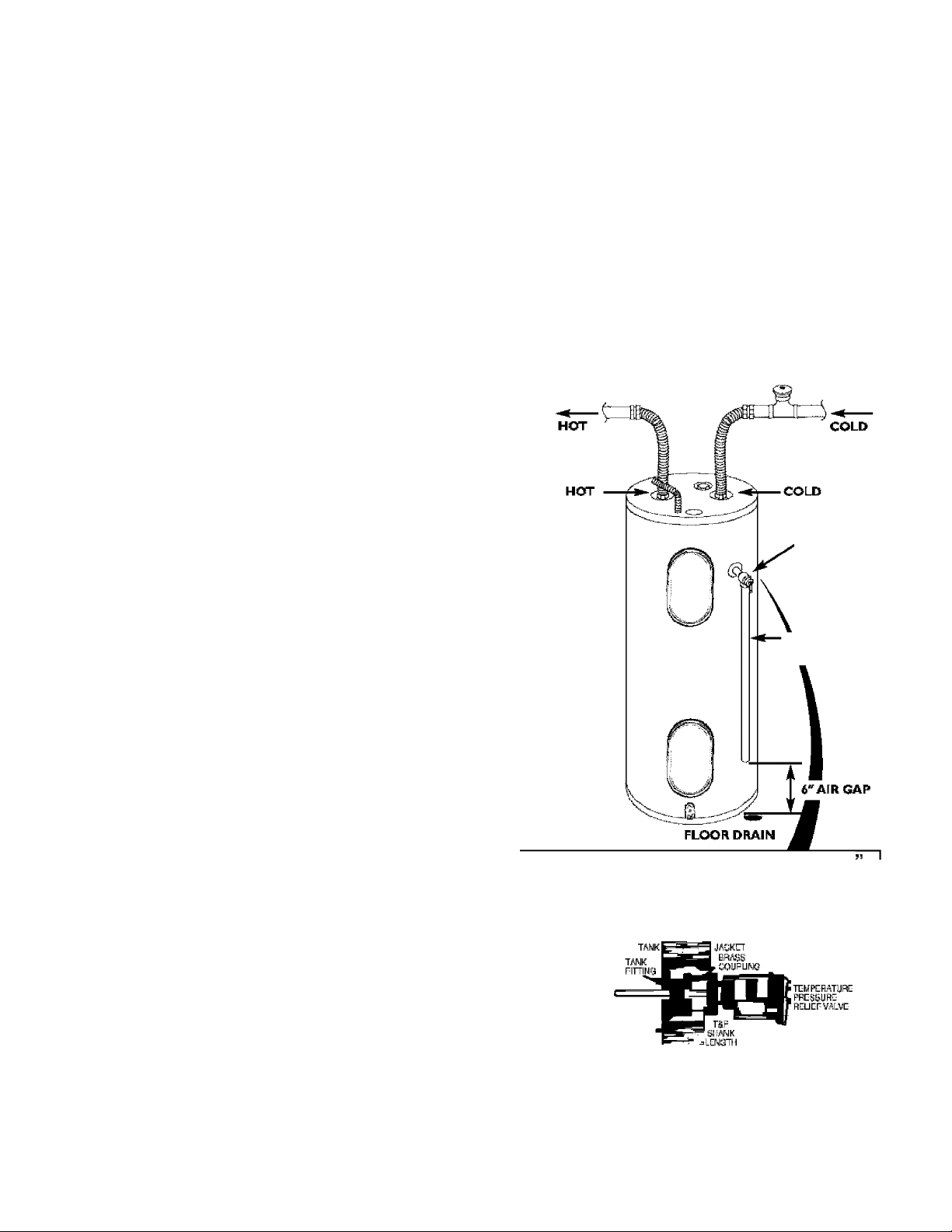
TEMPERATURE-
PRESSURE
RELIEF VALVE
' DISCHARGE PIPE
(Do not cap or plug)
WARNING “RELIEF VALVE OPENING
TMs hsgÈsr is piwitístí wfh e>rnbiftafcn Tsmiiaalui^isssíjfei flsisf Vaivs líaetí íompíyíiTg saih
lor ReJii' Valvg® and Autofnsüç WI loî Siipísíy Sysfenis, MiB SI
end ihç ADtiE.
Vsgi Icç^jiiri^ielicnal küíNíí%, rnairdsíiíig ihç isf ^ Teitií)ííraigi5-Pisí&ür^
e liwally prgsioribsd Tsit^raíiíf^-Prgísyi^ îiçlisf hslsJIsíJ in ih? ifesignaì&d cpening in ihç ss^r
hçetef-
'InstóllaqujifnsfììrsqulRHj ìjy IscalfcttìTisi tes®ilian açornblnBìten Temper^iirs-Pfessiifi^ Relish Valve seüífied as mesílrig tlie fsqiiiramsnis fer RíHisí V^lvís and
hg laixìfaìsfy thaï main^iTis psrfodç IrBjisdsn ot pràfiitlioir st listed ísqjipmení isf másríals. Tita va^
miKt be orèiTìsd, pníiiiJed №g. or iiisfellíHj so ílral di^har^ çaii sdì only ivííIiíti g ìiiof^
aîRsve, or at arw det^ice boiois ih§ stmctifal floor, and cariiría soTiiaoi «iiy If^ eleàrìo^l iiéì.“
Tor s0Js operalìoiT oì the ssaìer teater, the Relief miBí nsi be isnwsJ isf píiig^.
Seí> m^iTUíl heading ■ 'TampíHeliífe-PRsesure Relií^f ìer iiislallalisfi ana maiirionansa oí Rslíei
Valve, díssliarge ppe and sllisf pieeauítoiTs.
^ ift^ r^ir^ @ N10^ tn^rn tho Iuttiìsìi^ vuith tho h^r.
wfifi sudi itgsi 1;^ ^ ihg iiisisli^ srd Uier of iiis ii^r saih
TSF RCLIEF
VALVE PRC^BE
MUST EKTEND
ÌHTOTAHK
ÒRiiSS
NÌPPLT
• If a short shank (less tì^n 2") iempsiHUre-pr^uTs rslist te ì
(as a nìpplD and ©supling must Lo uo^.
• If a Ipng sharili (2" or fori^r) is te be ins^lsd, de noi tiss nipple arid ceupling.
SasShiiìeiT Dsvíí^íorlli3í-WateraipplyS^™MSZ21.22byanaíisf»al¥i^rio^
Page 10
Installation Instructions (cont’d)
Filling the Water Heater
To fill the water heater with water;
• Close the water heater drain vulve by turning the handle to
the right (clockwise). The drain valve is on the lower front of
the water heater,
• Open the cold water supply valve to the water heater,
NOTE; The cold water supply valve must be left open
when the water heater is in use.
• To insure complete filling of the tank, allow air to exit by
opening the nearest hot water faucet. Allow water to run
until a constant flow is obtained. This will let air out of the
water heater and the piping.
A CAUTION
Never use this water heater unless It Is complete^ full of
water. To prevent damage to the tank and heating ele
ment, the tank must be filled with water. Water must
flow from the hot water faucet before turning “ON”
power.
• Check all new water piping for leaks. Repair as needed.
Converting the Lower
Element
These instructions only cover the conversion of the convertible
elements read this entire manual before attempting to install or
operate the water heater. The water heater is factory set to oper
ate at 3800 watts. The lower element can be converted, to oper
ate at 5500 watts. Refer to the “Facts to Consider About the
Convertible liswcr FJement” section.
The Upper Elements (if a double clement model) is a conven
tional 3800 watt element which only operates at its rated
wattage on 240 volts, (See rating plate on water heater).
M COHRESPOd^l^ RE-
QAmtNQ THIS HESTER
mvB heifnOH ik
FACTORY SQUIPPED WITH
«ATT8 WATTS
OPTIONAL WATTAGE
OPPBR tgWR
ELECTRIC Wi
MODELNUMBER
V«Tra WATnS.::-lFCOWVEBTED::-
w*Tra A.C. DHCV IF AS ■ p,s,l
uwiuiw CHECK HERE ;
------------------
.TER HEATER
æHIALNUMEER
VC<.TS :.,VHfcUK If} nbric TiKpwNaweasiiBe
EQUIPPED
-------------^--------
WARNING
SEE CONVERSION
MsmucTiON
ECO
INSTALLED
150
NOTE; Whetlier or not. the element conversion is made the
model rating plate must be marked. Using a hard point ink
pen, check the appropriate block within the model rating
plate, which is located adjacent to tlie lower acc^s panel.
Necessary element conversion parts arc located in a small bag
contained within the electrical junction box on top of the water
heater.
CONVERSION PAFTTS
SCREW
The Lower Element of the water heater can be converted from
operation at 3800 watts to 5500 watts on a 240 volt system.
If after reading these instructions and this manual, if you do not
understand any portion, call Scars Service Center.
AWARNING
Before making the conversion to SSOO watts, check the
(I) power supply,..must be 240 volts, (2) wiring,,,10 gauge
AWG, Type TW, 60*C or equivalent, and (3) Circuit
brealmrs or fusing,„capable of 30 amp loading. Also, the
Installation must conform with this Manual, local codes
and electric utility rules. FAILURE TO COMPLY CAN
RESULT IN DEATH, SERIOUS BODILY INJURY OR
PROPERTY DAMAGE.
I , Before beginning the conversion turn “OFF” electric power
supply to the water heater.
IIKIPII
AWARNING
HAZARD OF ELECTRICAL SHOCK! Before removing
any access panels or servicing the water heater, make
sure the electrical supply to the water heater is turned
“OFF”. FAILURE TO DO THIS COULD RESULT IN
DEATH, SERIOUS BODILY INJURY, OR PROPERTY
DAMAGE,
10
Page 11

Installation Instructions (cont’d)
The convertible element is located, behind, the lower access
panel of the wmer hcatcj', 'Remove the two screws securing
the access panel, and remove panel.
3. Remove the insulation block and pad.
,5. Remove the screws from terminal 2 of the element, and. move
the looped end, of the wire asid e.
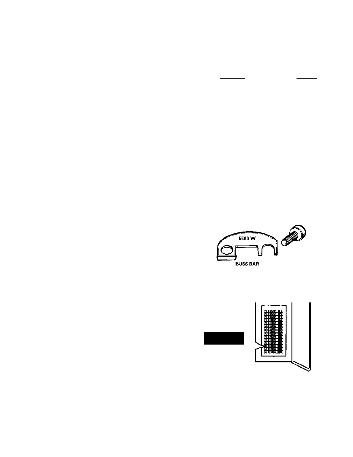
6. The buss bar is labeled 5.500 W. Place the buss bar over
terminals 2 and 3 with the 5.500 W visible. Install the extra
screw provided, into terminal 3.
The wire removed from terminal 2 has a looped end. It must
remain looped and now be placed (as shown) on top of the
buss bar, over the opening of terminal 2, and secured using
the remaining screw.
4. Lower Elemeut: Lift out the tab as shown to unclip the ter
minal cover from the thermostat. The terminal cover can be
removed from the thermostat.
8. Tighten terminals 2 and 3 to ensure proper electrical
connection.
AWARNING
Failure to tighten terminal screws can cause a Pre which
can result In DEATH, SERIOUS BODILY INJURY, OR
PROPERTY DAMAGE.
Page 12

Installation Instructions (cont’d)
Converting the Lower
Element (cont’d)
9. Replace tciminal cover on the thermostat, making sure the
notch is in place over the tab.
Tït sj*a?¥a
W 7SP OF
AWÂRNING
Make sure the thermostat Is flush against the tank, the
terminal cover is in place, and the Insulation Is replaced.
Failure to do so can result in DEATH, SERIOUS BODILY
INJURY, OR PROPERTY DAMAGE,
10. Replace the insulation block and pad so that it completely
covers the thermostat and element.
11, Replace the access panel.
12. Complete wiring to the water heater, or if completed, turn
“ON” electric power to the water heater after filling the
tank with water.
Bglllli
A CAUTION
Never use this water heater unless It Is completely full of
water. To prevent damage to the tank and heating ele
ment, the tank must be filled with water. Water must
flow from the hot water faucet before turning “ON”
power.
Page 13

Installation Instructions (cont’d)
Wiring Diagrams
STANDARD WIRING FOR
2 WIRE LEAD WATER HEATERS
NON-SIMULTANEOUS OPERATION
240 VOLT DOUBLE ELEMENT
TO ELECTRIC
POWER SUPPLY
WIRING FOR 3 WIRE LEAD WATER HEATERS
NON-SIMULTANEOUS OPERATION
240 VOLT DOUBLE ELEMENT
FOR 3800 WATTS
^NOTE: Some Lower Hi-Temp Limit
Switches may have 4 terminals. Use
only the 2 terminals on left.
YELLOW
LOWER
HEATING ELEMENT
:i3
1
TIME CLOCK SWITCH
OPERATES BOTTOM ELEMENT ONLY
TO ELECTRIC w
POWER SUPPLY
YELLOW I TBLUe|BLACÍC
«OFF PEAK” METER
OPERATES BOTTOM ELEMENT ONLY
TO ELECTRiC
POWER SUPPLY LI
FOR TWO WIRE CONNECTION
POWER SUPPLY
LI
^ 9
yellow!
THREE TYPES OF FIELD
CONNECTIONS YOU MAY
HAVE
TO TÍME
L2 L2 clcx:íc switch
JUNCTION SOX
I2l-'L2 TO^'OFF
- PEAK” MCTER
JUNCTION BOX
------
1
L2
JUNCTION BOX
TbLU^ BLACK
Page 14

Installation Instructions (cont’d)
Wiring
A CAUTION
Never use this viater heater unless it is completely full of
water. To prevent damage to the tank and heating ele
ment, the tank must be filled with water. Water must
flow from the hot water faucet before turning on power.
You must provide all wiring of the proper sixe outside of the
water heater. You must obey local codes and. electric company
requirements when you install this wiring.
If you arc not familiar with electric codes and practices, or if you
have any doubt, even the slightest doubt, in your ability to con
nect the wiring to this water heater, obtain the service of a com
petent electrician. Contact your Scars salesperson to arrange for
a professional electrician.
AWARNING
WATER HEATERS EQUIPPED FOR ONE VOLTAGE
ONLY: This water heater Is equipped for one type voltage
only. Check the rating plate near the bottom access panel
for the correct voltage. DO NOT use this water heater
with any voltage other than the one shown on the model
rating plate. Failure to use the correct voltage can cause
problems which can result In DEATH, SERIOUS BODILY
INJURf, OR PROPERTY DAMAGE. If you have any ques
tions or doubts consult your electric company.
C, Flexible metal conduit or flexible metallic tubing shall be
permitted for grounding if all the following conditions arc
met:
1, The length in any ground, return path docs not exceed
6 feet,
2, The circuit conductors contained, therein arc protected
by overcurrent devices rated at 20 amperes or less,
3, The conduit or tubing is terminated in Fittings
approved for grounding.
For complete grounding details and all allowable exceptions,
refer to the current edition of the National FJectrical Code,
NFPA70.
4, A standard. V” cond.uit opening has been made in the water
heater junction box for the conduit connection.
3, Wiring Diagrams (See Wiring Diagrams Section) have been
supplied, showing the two most common types of connec
tions between the water heater and. the power supply. You can
easily sec which type connection you have by removing the
junction box cover on top of the water heater,
A, Two WTre Counecticui Diagrams! is the most common
requiring you to simply connect red to red., black to black,
and the ground wire to the green ground screw in the junc
tion box of the water heater,
A CAUTION
If wiring from your fuse box or circuit brealrer box was
aluminum for your old water heater, replace It with cop
per wire. If you wish to reuse the existing aluminum wire,
have the connection at the water heater made by a com
petent electrician. Contact your Sears salesperson to
arrange for a professional electrician.
1. Piovid.c a way to easily shut off the electric power when
working on the water heater. This could, be with a circuit
breaker or fuse block in the entrance box or a separate dis
connect switch,
2. Install and. connect a circuit directly from the main fuse or
circuit breaker box. This circuit must be the right she and
have its own fuse or circuit breaker. Refer to the chart in the
“Product Specifications” section for the correct sixe wire and
fuse or circuit breaker,
3. If metal conduit is used for the grounding conductor:
A, The grounding electrode conductor shall be of copper,
aluminum, or coppcrclad aluminum. The material shall
be of one continuous length without a splice or joint.
B. Rigid metal conduit, intermediate metal conduit, or elec
trical metallic tubing may be used for the grounding
means if conduit or tubing is terminated in fittings
approved, for grounding.
B. Three Wire Counection Diagmau is used when you arc
connecting the water heater to power a supply that has a
“Time Clock” or “Off Peak” Meter, To make these connec
tions refer to block i or 2 in this wiring diagram for the type
of system you h ave,
NOTE: If you have purchased, a three wire comiectiou
water heater but yow are not on a “Time Clock” or “OIF
Peak” meter and have a standard two wire connection
power supply, simply follow the connection diagram in
block 3. of the Three Wj« Connection Diagram.
6. Use wire nuts and. connect the power supply wiring to the
wires inside the water heater’s junction,
7. The water heater must be electrically “grounded” by the
installer. A green ground screw has been provided, on the
water heater's junction box. Connect ground wire to this
location.
8. Replace the wiring junction cover using the screw provided.
14
Page 15

Installation Instructions (cont’d)
Installation Checklist
'Whether 01 not the element conversion is made, the model
rating plate must be marked. Using a hard point ink pen,
check the appropriate block within the model rating plate,
which is located adjacent to the lower access panel.
Is the fuse or circuit breaker sixe correct as shown in the chart
in the “Product Specifications” section?
Arc the wires from the circuit breaker or fuse service to the
water heater's junction box on the correct wire size (gauge) as
shown in the chart in the “Product Specifications” section?
Is the new tcmpcraturc'prcssure relief valve properly
installed, and piped, to an ad.equate drain? See “TemperaturePressure Relief’Valve” section.
Is the water heater completely fdled. with water? See “Filling
the "Water Heater” instructions in the “Installation
Instructions” section.
Will a water leak damage anything? Sec “Facts to Consider
About the location” section.
Arc the cold and hoc water lines connected to the water heater
correctly? Sec “Water Piping” instructioas iu the “Instalktion
rascruccions” section.
COLD
Is there adequate clearance for maintenance around the water
heater?
Do you need to call your electric company to check your
wiring?
ELECTRIC ¥WIER HEATER ego
KRUtW HJKMeir !№№liU HlStllB í(iiSSíi»5ÍWWíC
WATTS wftTTfi ag
OPTIONAL WATTABe . .V, EQUff»P€D
iAAMWÜgy CHECK i ^
1
WMTB liMrrrB IF CONVERTED
DISCHARGE PIPE
(Do not cap or plug)
OAFASn-y SEfilALWUWSBi:
1
yAtsM,. :
ivHT . 150
ífi'’'- IHSTRIJÍCTKSÍ
6* AIR GAP
MODEL RATING PLATE
Page 16

Service and Adjustment
Temperature Regulation
AWARNING
HOTTER WATER CAN SCALD; Water heaters are
intended to produce hot water. Water heated to a tem
perature which will satisfy space heating, clothes washing,
dish washing, and other sanitizing needs can scald and
perrranently injure you upon contact. Sorre people are
more likely to be permanently injured by hot water than
others. These include the elderly, children, the infirm, or
physically/mentally handicapped. If anyone using hot
water in your home fits into one of these groups or if
there is a local code or state law requiring a certain tem
perature water at the hot water tap, then you must take
special precautions. In addition to using the lowest possi
ble temperature setting that satisfies your hot water
needs, a means such as a mixing valve, shall be used at
the hot water taps used by these people or at the water
heater. Mixing valves are available at plumbing supply or
hardware stores. Follow manufacturers instructions for
installation of the valves. Before changing the factory set
ting on the thermostat, read the "Temperature
Regulation" section in this manual.
AWARNING
Never allow small children to use a hot water tap, or to
draw their own bath water. Never leave a child or handi
capped person unattended in a bathtub or shower.
The lower thermostat is factory set at a position which approxi
mates 120*'F (HOT) and is adjustable it a different water tem
perature is desired. Read, all warnings in this manual and on the
water heater before proceeding.
ADJUSTABLE LOWER
THERMOSTAT
(2 wire lead models)
ADJUSTABLE LOWER
THERMOSTAT
WITH HIGH LIMIT
(3 wire lead models)
Thermostats
The thermostat(s) of this water heater have been factory set at a
position which, approximates 1.20“F (HOT) to red.ucc the risk of
scald injury.
The upper thermostat is factory set at a position which approxi
mates 1.20“? (HOT) and, is adjustable if a different water tem
perature is desired. Read, all warnings in this manual and on the
water heater before proceeding.
UPPER THERMOSTAT ADJUSTABLE
BEHIND UPPER ACCESS PANEL
Temperature Settings
HOT-Is a thermostat setting of approximately IRO^F,
which will supply hot wutcr at the most economi
cal temperatures.
A-Is a thermostat setting of approximately ITO^F.
B-Is a thermostat setting of approximately I40“F,
C-Is a thermostat setting of approximately t 30'’F.
VERY HOT-ls a thermostat setting of approximately 1.60“E It
is recommended that the dial be set lower when
ever possible.
NOTE; Water temperature range of 120“—^140"F recom
mended by most dishwasher manufoctarers.
Tiiivy u> Pi'iirdijj;,!“
'¿iid ÿt 3fd
Eiurni C'li Addi.. 5l<iii
[«T
l5(fF
ItOT
I30T
I20“F
AtiDiA 1/2 seconds
Attouir 1-1/2 seconds
Less than 5 seconds
Aboyrt 30 seconds
More tlian 5 minutes
1.6
Page 17

Service and Adjustment (cont’d)
Upper and Lower Thermostat
Adjustment
{Refer to thermostat illustrations under
“Thermostats”)
NOTE: It is not necessary to adjtist tlie upper thermostat.
However, if it is ad.j«isted above tke factory set point of
120“F (НСУГ) is is recommended that it not be set higher
than the lower thennostat setting.
The upper and lower thermostats are adjustable if a different
water temperature is desired,. Read all warnings in the
“Temperature-Regulation” section before proceeding.
L Turn “OFF” the dcctiical power to the water heater at the
junction box.
2. Take off the upper and/or lower access panel, insulation
block and pad,
3. The slotted, adjustment (using a screwdriver) can be turned
clockwise ( to increase the temperature setting or
counter clockwise (
setting,
4. Replace the insulation block, pad, and, access panel.
3. Turn “ON” the power supply.
______
to decrease the temperature
Failure to install and maintain a new properly listed, temperaturc-pressure relief valve will release the manufacturer from any
claim which might result from excessive temperature or pressure.
AWARNING
If the temperature-pressure relief valve on the appliance
weeps or discharges periodically, this be due to ther
mal expansion. Your water heater m^ have a check valve
Installed In the water line or a water meter with a check
valve. Consult your local Sears Service Center for further
Infbnnatlon, Do not plug the temperature-pressure relief
valve.
Draining
The water heater should be drained, if being shut d,own d,uring
ffcc/ing tcmpciaturcs, .Also periodic draining and, cleaning of
sediment from the tank may be necessary,
• Before beginning turn “OFF” the electric power supply to the
water heater.
Temperature-Pressure Relief Valve Operation
The tem perature-pressure relief valve must be manually operated
at least once a year,
TEMPERATURE-PRESSURE
AWARNING
The temperature-pressure relief valve must be manually
operated at least once a year. Caution should be taken to
ensure that (I) no one is in front of or around the outlet of
the temperature-pressure relief valve discharge line, and (2)
the water manually discharged will not cause any proper^
damage or bodily injury. The water may be extremely hot.
If after manually operating the valve, it fails to completely
reset and continues to release water, immediately close the
cold water inlet to the water heater, follow the draining
Instructions, and replace the temperature-pressure relief
valve with a new one.
AWARNING
HAZARD OF ELECTRICAL SHOCK! Before removing
any access panels or servicing the water heater, make
sure the electrical supply to the water heater Is turned
“OFF”, Failure to do this could result In DEATH, SERI
OUS BODILY injury; OR PROPERTY DAMAGE,
• CLOSE the cold water IrLlct valve to the water heater,
• OPEN a nearby hot water faucet and leave open to allow for
draining,
• Connect a hose to the drain valve and terminate to an
adequate drain or outdoors,
• OPF.N the water beater drain valve to allow for tank draining.
NOTEt If the water beater is going to be shut down and
drained for on extended perioi^ tbe drain valve sbotdd be
left open witb hose connected allowing water to terminate
to on adequate drain,
• Close the drain valve.
• Follow “Filling the Water Heater” instructions in the
“Installation Instructions” section,
• Turn “ON” power to the water heater.
A CAUTION
Never use this water heater unless it is completely full
water. To prevent damage to the tank and heating ele
ment, the tank must be filled with water. Water must
flow ftom the hot water faucet before turning “ON”
power.
Page 18

Service and Adjustment (cont’d)
Element Cleaning/
Replacement
NOTEi Tkese iiistractiofis are "writteii for efomeut clmuiiig
aud element replacemeut for the lower element. If it is iieces'
sary to clean or replace the upper element, then repeat tli^e
instructions.
To remove the element from youi tank in order to clean or
replace it:
1. Before beginning turn “OFF” the electric power supply to the
water heater.
(•■lll'MIin
<Bllli*lin
|)-Hr
iiO
|| JI.HRill 1
H 1" Ili1
>■
Hi
\i
1l-
111 I
Hi 11 It.
tin
hr
IJ- r.»■ ti:i
EKlIIJi
r>l 11- Jh.-■ IT J
infr
■ U.1
inh
-■
■ in
Ivl■1lull*
■ in
uni*
■ R:l
AWARNING
HAZARD OF ELECTRICAL SHOCK! Before removing
any access panels or servicing the water heater, make
sure the electrical supply to the water heater Is turned
“OFF”, Failure to do this could result In DEATH, SERI
OUS BODILY injury; or property damage.
Turn off the water supply to the water beater at the water
shutoff valve or water meter.
4, Remove the two screws securing the access panel, and. remove
panel.
5, Remove the insulation block and pad.
6, lift out the tab as shown to unci ip the terminal cover from
the thermostat. The terminal cover can now be removed
from the thermostat.
3. Attach a hose to the water heater drain valve and put the
other end in a floor drain or outdoors. Open the water heater
drain valve. Open a nearby hot water faucet which will relieve
pressure in the water heater and speed draining.
AWARNING
The water passing out of the drain valve may be extremely
hot. To aw>id being scalded, make sure all connections are tight
and that the water flow is directed aw^ from any person.
18
Page 19

Service and Adjustment (cont’d)
10. A new gasket should, be used, in all cases to prevent a possi
J)1 y
TERMINAL
COVER ON
UPPER
THERMOSTAT
Disconnect the two wires on the element and unscrew the
old element from the tank.
ble water leak. (See Element Gasket in the “Parts Order
list” Chart). Place the new clement gasket on the thread
side of the cleaned or new element and screw into tank,
securing tightly using an element wrench.
Close the water heater drain valve by turning the handle to
II.
the right (clockwise). The drain valve is on the lower front
of the water heater.
12.
Open the cold wuter supply valve to the wuter heater,
NOTEs The cold, water supply valve must be left орем
when the water heater is in tise.
To insure complete filling of the tank, allow air to exit by
13.
opening the nearest hot water faucet. Allow water to run
until a constant flow is obtained. This will let air out of the
water heater and the piping.
8. Clean the area around, the clement opening. ^Remove any
sediment from or around the element opening and inside
the tank.
9. If you are cleaning the clement you have removed, do so by
scraping or soaking in vinegar or a d.e'liming solution.
AWARNING
Replacement elements must (I) be the same voltage and
(2) no greater wattage than listed on the model rating
plate affixed to the water heater.
A CAUTION
Never use this vtater heater unless it Is completely full of
water. To prevent damage to the tank and heating ele
ment, the tank must be filled with water. Water must
flow from the hot water faucet before turning “ON”
power.
14,
Check element for wmer leaks. If leakage occurs, tighten
element or repeat steps 2 and 3, remove clement and, reposi
tion gasket. Then repeat steps 10 through 14,
Reconnect the two wires to the dement and. th.cn check to
15.
make sure the thermostat remains firmly against the surface
of the tank.
T)
Page 20

Service and Adjustment (cont’d)
Element Cleaning/
Replacement (cont’d)
16. Replace the terminal cover on thermostat,
X/'
17. Replace the insulation block and pad, so that it com
covers the thermostat and, element.
This does not affect the waters taste or color. The rod, must be
maintained to keep the tank in operating condition,
,4nodc d,ctcrioration d,cpcnds on water conductivity, not neces
sarily water condition, A corroded or pitted anode rod indicates
high water conductivity and should be checked and/or replaced
more often than an anode rod that appears to be intact.
Replacement of a depleted anode rod can extend the life of your
water heater. Inspection should be conducted, by a Scars service
technician, and at a minimum should, be checked annually after
the warranty period,.
Drain Valve Washer
Replacement
NOTEi For replacemeut, use a x x Yf thick washer
available at. yonr nearest hardware store. For ordering a
replacement washerj refer to the “Parts Order List” section,
• Before beginning turn “OFF” the electrical power supply to
the water heater.
AWARNING
HAZARD OF ELECTRICAL SHOCK! Before removing
any access panels or servicing the water heater, make
sure the electrical supply to the water heater Is turned
“OFF”, Failure to do this could result In DEATH, SERI
OUS BODILY injury; or property damage.
18. Replace access panel.
19. Turn “ON” electric power to water heater.
A CAUTION
Never use this water heater unless It is completely full of
water. To prevent damage to the tank and heating element,
the tank must be filled with water. Water must flow from
the hot water faucet before turning “ON” power.
Anode Rod Inspection
The anode rod is used, to protect the tank from corrosion. Most
hot water tanks are equipped with, an anode rod. The sub
merged rod sacrifices itself to protect the tank. Instead, of cor
roding the tank, water ions attack and cat away the anode rod.
Follow “Draining” instructions in the “Service and
Adjustment” section.
Turning counter clockwise, remove the hex cap below the
screw handle.
Remove the washer and put the new one in place.
Screw the handle and cap assembly back into the drain valve
and retighten using a wrench, DO NOT OVERTIGHTEN.
Follow “Filling the Water Heater” instructions in the
“Installation Instructions” section.
Check for leaks.
Turn “ON” electric power to the water heater.
Service
Before calling for repair service, read the Start Up Conditions
and. Operational Conditions found, in the Troubleshooting
Guide of th is manual.
If a condition persists or you are uncertain about the operation
of the water heater, let a qualified, person check it out.
Contact SEARS Repair Services at l-SOO-d-MY-HOME
(1-800-469-4663).
Page 21

Troubleshooting Guide
Start Up Conditions
THERMAL EXPANSION
Water supply systems may, because of such events as high line
pressure, frequent cut-offt, the effects of water hammer among
others, have installed devices such as pressure reducing valves,
check valves, back flew preventers, etc,,,to control these types of
problems. When these devices arc not equipped with an internal
by-pass, and. no other measures arc taken, the devices cause the
water system to be closed. As water is heated, it expands (ther
mal expansion) and, closed, systems do not allow for the expan
sion of heated water.
The water within the water heater tank expands as it is heated and
in creases the pressurc of the water sj’stem. If the rel ieving point of
the water heater's temperature-pressure relief valve is reached, the
valve will relieve the excess pressure. The teinperatune-piessiure
reHef valve is not inteud.ed for the constant relief of thermal
expansion. This is an unacccpable condition and must be cor
rected.
It is rccommend.ed, that any d.evices installed, which could create a
closed, system have a by-pass and/or the system have an expan
sion tank to relieve the pressure built by thermal expansion.
Thermal expansion tanks arc available from Scars stores and
through the Scars Service Centers, Contact the local plumbing
inspector, water supplier and/or the Scars Service Center for
assistance in controlling these situations.
WATER HEATER
COLD WATER
INLET FITTIMG
FLOOR, CEILING
JOIST, ETC.
Thermal Expansion Tank Specifications
Model
Number
153.331020
153.331050 5
Tank Capacitv
In Gallons
Dimensions in Inches
Diameter Length.
8 inches
■] ■] inches
12% inches
14% inches
Pipe Fitting
On Tank
Male
y/' Male
Expansion Tank Sizing Chart
Inlet*
Water
Expansion
Tank
Capacity
Needed
*Highcst recorded inlet water pressure in a 24 hour period or
regulated, water pressure,
NOTE; Expansion tanks arc prc-chargcd with a 40 psi air
charge. If the inlet water pressure is higher than 40 psi, the
expansion tank’s air pressure must be adjusted to match that
pressure, but must not be higher than 80 psi.
Pressure
40 psi
50psi
60psi
70psi
80psi
Water Heater Capacity (Gallons)
30 40 50 66 80
5 5
2
2 jC.
2 jC.
2
5 5 5
5 5 5
5 5 5 5
5 5
STRANGE SOUNDS
Possible noises due to expansion and contraction of some metal
parts during periods of heat-up and cool- down do not represent
harmful or dangerous conditions.
Page 22

Troubleshooting Guide (cont’d)
Operational Conditions
SMELLY WATER
Tn each water heater there is installed at least one anode rod (see
parts section) for corrosion protection of th e tank. Certain water
conditions will cause a reaction between this rod, and the water.
The most common complaint associated with the anode rod is
one of a “rotten egg smell”. This odor is derived from hydrogen
sulfide gas dissolve in the water. The smell is the result of fxsur
factors which must all be present for the odor to develop;
a, a concentration of sul fate in the supply water,
b, little or no dissolved oxygen in the water,
c, a sulfate reducing bacteria within the water heater,
(This harmless bacteria is non- toxic to humans.)
d, an excess of active hydrogen in the tank. This is caused
by the corrosion protective action of the anode.
Smelly water may be eliminated or reduced in some water heater
models by replacing the anodc(s) with one of less active material,
and then chlorinating the water heater tank and all hot water
lines. Contact the local Scars Service Center for further informa
tion concerning an .Anode Replacement Kit #9001453 and this
Chlorination Treatment,
If th e smelly water persists after the anode replacement and, chlo
rination treatment, we can only surest that continuous chlori
nation and, filtering conditioning equipment be considered to
eliminate the water problem.
Do uot remove tlie auode leaving the tank unprotected. By
doing so, all warranty on the water heater tank is voided.
RUMBLING NOISE
In some water areas, scale or mineral deposits will build up on
your beating dements. This build,up will cause a rumbling noise.
Follow “Element Cleaning/'Rcplaccment” instructions to clean
and, replace the elements.
HIGH TEMPERATURE SHUT OFF SYSTEM
The water heater has a high, limit shut off system with a reset
button located on the thermostat.
Follow the resetting instructions which refer to the high limit
behind the access panel,
NOTE; If your water heater is connected to an “OFF PEAK”
clock, and uses the “3 wire lead” wiring diagram in the
“‘Wiring Diagram” section, then the vrater heater will have a
hi'liinit on both the upper and lower thermostats. Follow
the instmetions to reset the hhlimit behind the upper and
lower access panels,
• Before beginning, turn “OFF” electrical power supply to the
water heater.
"/IfR" IN HOT WATER FAUCET’S
AWARNING
HYDROGEN GAS: Hydrogen gas can be produced in a
hot water system that has not been used for a long peri
od of time (generally two weeks or more). Hydrogen gas
is extremely flammable and explosive. To prevent the
possibility of injury under these conditions, we recom
mend the hot water faucet be opened for several min
utes at the kitchen sink before any electrical appliances
which are connected to the hot water system are used
(such as a dishwasher or washing machine). If hydre^en
gas Is present, there will probably be an unusual sound
similar to air escaping through the pipe as the hot water
faucet is opened. There must be no smoking or open
flame near the faucet at the time It Is open.
AWARNING
HAZARD OF ELECTRICAL SHOCK! Before removing
any access panels or servicing the water heater, make
sure the electrical supply to the water heater Is turned
“OFF”, Failure to do this could result in DEATH, SERI
OUS BODILY
injury; or PROPERTY DAMAGE.
Page 23

Troubleshooting
(cont*d)
HIGH TEMPERATURE SHUT OFF SYSTEM
(cont’d)
• Remove the two screws securmg the access panel and remove
panel,
• Remove the insulation block and. pad,
• Reset the high limit by pushing in the red button marked
“RESET”. ■
-RESET BUTTON
• Replace the insulation block and, pad so that it com'
covers the thermostat and element.
• Replace the access panel,
• Turn “ON” electric power to the water heater.
NOT ENOUGH OR NO HOT WATER
• In a new installation, the water heater may not be properly
connected. Make sure the cold water supply valve is open.
Review and, check piping installation. Make sure that the
cold water line is connected to the cold water inlet to the
water heater and. the hot water line to the hot water outlet
on the water heater.
• Make sure the electrical supply to your water heater is
“ON”, ■ ■
• Cheek for loose or blown fuses in your water heater circuit.
Circuit breakers weaken with age and may not handle their
rated load, and. should be replaced,.
• Make certain the disconnect switch, if used, is in the “ON”
position,
• Cheek to see the electric service to your house has not been
interrupted. If this is the ease, contact the electric company,
• Arc the thermostats set to the desired temperature? See
“Temperature Regulation” section,
• If you had experienced very hot water and now no hot
water, the problem may be due to the high temperature
shut off system. See “High Temperature Shut Off’ System”
in the “Troubleshooting” section.
• During very cold, weather, the incoming water will also be
colder and, it will require a longer time to become heated.
A CAUTION
If the high limit must be reset again, call Sears Service
Department to find out why the high limit turned “OFF”
the electric power.
• The hot water usage may exceed the capacity of the water
heater. If so, wait for water heater to recover after abnormal
demand,. .Also examine pipes and faucet’s for possible water
leaks,
• rf you can not determine the problem, then call the Scars
Service Department.
WATER IS TOO HOT
Adjust the thermostat to a lower setting. See the “Temperature
Regulation” section.
Page 24

Troubleshooting
Leakage Checkpoints
(cont*d)
Use this guide to check a “Leaking” water heater. Many suspect
ed “Leakers” are not leaking tanks. Often the source of the water
can be found and, corrected.
rf you arc not thoroughly familiar with electric codes, the water
heater, and, safety practices, contact your local Scars Service
Center to check the water heater.
^A) *Cond,cnsation may be seen on pipes in humid weather
or pipe connections may be leaking.
The primary anode rod, may be leaking.
Small amounts of water from temperature-pressure
relief valve may be due to thermal expansion or high
water pressure in your area.
*Thc temperature-pressure relief valve may be leaking at
the tank fitting.
The elements may be leaking at the tank fitting.
A WARNING
HAZARD OF ELECTRICAL SHOCK! Before
removing any access panels or servicing the water
heater, make sure the electrical supply to the
water heater is turned “OFF”, Failure to do this
could result in DEATH, SERIOUS BODILY
INJUFTT, OR PROPEFtTY DAMAGE.
A CAUTION
Read this manual first, then before checking the water
heater make sure the electric supply has been turned
“OFF”, and never turn the electric supply “ON” before
the tank is completely full of water.
Turn electrical power “OFF”, remove access panels and
insulation block and, pad. If leaking around, elements,
follow proper draining instructions and remove
clement. Reposition or replace gasket on dement. Place
clement into opening and tighten securely. Then follow
“Filling the Water Heater” instructions in the
“Installation Instructions” section.
Water from drain valve may be d,uc to the valve being
^ ^ opened, slightly.
*The drain val ve may be leaking at the tank fitting.
*Watcr in the water heater bottom or on the floor may
be from condensation, loose connections or the
temperature-pressure relief valve. DO NOT replace
the water heater until a full inspection of all possible
water sources is made and necessary corrective steps
taken,
I,cakagc from other appliances, wutcr lines, or ground
seepage should, also be checked,
NOTE; *To check where threaded portiou enters
tank, insert cotton swab bctwecii jacket opening and
fitting. If cotton is wet, follow “TImining” instmetions in the “Service and Adjustment” section and
then remoTO fitting. Put pipe dope or teflon tape on
the threads and replace. Then follow “PUliag the
Water Heater” instructions in the “Installation
Instructions!” section.
24
Page 25

Notes
Page 26

Notes
Page 27

Notes
Page 28

Parts Order List
KE?iMORE POWER MISER™ 12 ELECTRIC WATER HEATERS
MODEL NUMBERS;
153.321340 30 CkJ.
153.321341 30 CkJ.
153.321440 40 CkJ.
153.321441 40 CkJ.
153.321540 50 Gal.
NOTE; A
UPPER ELEMENT; These water heaters are equipped witli
3800 watt eleineiiite.
LOWER ELEMENT; These water heateis axe equipped witli
iactoxy imtalled coirvextible elemeniSj which can. be operated
at 3800 watts or 5500 watts. Convertible elements are not
offered as replacemeut parts.
ELEMENT ORDERING INFORMATION
If a replaccinent 3800 watt, 240 volt element is needed, order
item no. 42-31906 replacement element. If at tlie time of instal
lation, tlie water better was converted to operate at 5500 watts.
Older item number 42-31908 replacement element. (See model
rating plate “If Converted” box).
NOIE;B
These water heaters are equipped with a Rofo-Swirl™ dip
tube to retard a build-up of dissolved solids.
Page 29

Parts Order List (contad)
KENMORE POWER MISER™ 12 ELECTRIC WOER HESTERS
MODEL NUMBERS:
153.321340
153.321341
153.321440
153.321441
153.321540
KEY
NO.
PART
DESCRIPTION
1, Tempemture-Pressure Relief Valve*
Heat Trap Nipple (Cold Inlet)
Secondary .Anode w/Heat Trap Nipple (Hot Outlet)
3,
4, Roto- Swirl™ Dip Tube (Sec NCyTR “B” page 28}
Drain Valve
3,
Drain Ysht msher (%"x r thick)**
6,
'7
Fdement Gasket 9000308 9000308 9000308 9000308 9000308
8, luwcr F,lcment* (See NOTE “A”on page 28) 3800 Watt
Buss Bar Kit
9,
10. Tlietmostat Bracket
n. 2 Pole Thermostat (Two Wire Lead Modcls'i'i’*
12.
Terminal Cover & Barrier
luwcr Thermostat w/Hi I.imit
13.
(Three Wire lead Modds)tt*
14.
Terminal Cover
lower Access Panel
15.
16. Upper Access Panel
Terminal Cover
17.
Upper Thermostat w/Hi Limit*
18.
Tlietmostat Bracket
19.
20. Upper Element* (See NOTE “A” page 28) 42 31906 42 31906 42 31906 42 31906 42 31906
21. Fdement Gasket
22.
23.
Model Rating Plate t
Primary Anode
//
Manual 184730-000
30 Gal.
30 Gal.
40 Gal.
40 Gal.
50 Gal.
MODEL NUMBERS
153.321340
153.321341
153.321440
153.321441
153.321540
PART NUMBERS
9002403 9002403 9002403 9002403 9002403
9003931 9003931 9003915 9003915 9003909
9003937 9003937
9003501 9003501
9003911 90039II
9003941 9003941
9003939
9003929 9003929 9003919
9003098 9003098 9003098
9001584 9001584 9001584 9001584 9001584
42 31906
5500 “Watt
42 31908
3800 Watt
42 31906
5500 Watt
42 31908
3800Watt
42 31906
5500 'Watt
42 31908
3800 Watt
42 31906
5500 Watt
42 31908
3800 'Watt
42 31906
5500 'Watt
42 31908
9001591 9001591 9001591 9001591 9001591
9000309 9000309 9000309 9000309 9000309
42 31919
9002276
—
-
—
-
4231918
9002303
42 31919
9002276
—
-
-
-
42 31918
9002303
42 31919
9002276
9002671 9002671 9002671 9002671 9002671
9002671 9002671 9002671 9002671 9002671
9002303 9002303 9002303 9002303 9002303
42 31917 42 31917 42 31917 42 31917 42 31917
9000309 9000309 9000309 9000309 9000309
9000308 9000308 9000308 9000308 9000308
0270182 0270182 0270182 0270182 0270182
9003927 9003927
9003928 9003928 9003728
—
-
*Thcsc parts arc also available at most Scars retail stores.
**Also available at most hardware stores.
tRcplaccd only on return of damaged plate,
ttl^fcr to 'Wiring Diagram Section for verification,
//Not Illustrated
Now that you have purchased this water heater, should a need ever exist for repair parts or service, simply contact any SEARS Service
Center or call l'-800-4-MY-HOME (l'-800-469-4663). Be sure to provide all pertinent facts when you call or visit.
.All parts listed may be ordered from any SFJ^RS Service Center, most Scars stores and by calling 1- 800- 366-P.ART (1-800- 366-7278).
If the parts you need arc not stocked locally, your order will be electronically transmitted to a SEARS Repair Parts Distribution Center for
handling.
The model number of the water heater will be found on the model rating plate located above the access panel,
'WHEN ORDERING REPAIR PARTS, ALWVYS GIVE THE FOLLOWING INFORMAnONi
MODEL NUMBER PART DESCRIPTION
SERIAL NUMBER PART NUMBER
THIS IS A REPAIR PARTS LIST, NOT A PACKING USX
29
Page 30

Parts Order List
KE?iMORE POWER MISER™ 12 ELECTRIC WATER HEATERS
MODEL NUMBERS;
153.321541 50 CkJ.
153.321640 66 CkJ.
153.321641 66 CkJ.
153.321840 80 CkJ.
153.321841 80 Gal.
NOTE; A
UPPER ELEMENT; These water heaters are equipped witli
3800 watt eleineiiite.
LOWER ELEMENT; These water heateis axe equipped with
iactoxy imtalled coirvextible elemeniSj which can. be operated
at 3800 watts or 5500 watts. Convertible elements are not
offered as replacemeut parts.
ELEMENT ORDERING INFORMATION
If a replaccinent 3800 watt, 240 volt element is needed, order
item no. 42-31906 replacement element. If at tlie time of instalktion, tlie water better was converted to operate at 5500 watts.
Older item number 42-31908 replacement element. (See model
rating plate “If Converted” box).
NOIE;B
These water heaters are equipped with a Roto-Swirl™ dip
tube to retard a build-up of dissolved solids.
30
Page 31

Parts Order List (contad)
KENMORE POWER MISER™ 12 ELECTRIC WOER HESTERS
MODEL NUMBERS:
153.321541
153.321640
153.321641
153.321840
153.321841
KEY PART 153.321541
NO. DESCRIPTION PART NUMBERS
1,
Tempemture-Pressure Relief Valve*
A,,
Heat Trap Nipple (Cold Inlet)
Secondary .Anode w/Hcat Trap Nipple (Hot Outlet)
3,
4,
Roto-Swirl™ Dip Tube (Sec NCyTR “B” page 30}
Drain Valve
3,
Drain Vdve msher (%"x r thick)**
6,
'7
Element Gasket 9000308 9000308 9000308 9000308 9000308
8, I ower Elément* (See NOT.R “A” on pagc30) 3800 Watt
Buss Bar Kit
9,
10. Tlictmostat Bracket
ri. 2 Pole Thermostat (Two Wire Lead Modcls'î'^"*
12.
Terminal Cover & Barrier
lower Thermostat w/Hi limit
13.
(Three Wire lead Modds)tt*
14.
Terminal Cover
lower Access Panel
15.
16. Upper Access Panel
Terminal Cover
17.
Upper Thermostat w/Hi Limit*
18.
Thermostat Bracket
19.
20.
21.
22.
23.
Upper Riement* (See NOTE “A” page 30)
Element Gasket 9000308 9000308 9000308 9000308 9000308
Model Rating Plate t
Primary Anode 9003728
//
Manual 184730-000
50 Gal.
66 Gal.
66 Gal.
SO Gal.
80 Gal.
MODEL NUMBERS
153.321640
1.53.321641
153.321840
9002403 9002403 9002403 9002403 9002403
9003909 9003931 9003931
9003939
9003940 9003940
9003919 9003933 9003933 9003933 9003933
9003098 9003098 9003098 9003098 9003098
9001584 9001584 9001584 9001584 9001584
42 31906
5500 “Watt
42 31908
3800 Watt
42 31906
5500 Watt
42 31908
3800Watt
42 31.906
5500 'Witt
42 31908
3800 Watt
5500 Watt
9001591 9001591 9001591 9001591 9001591
9000309 9000309 9000309 9000309 9000309
-
-
42 31918
9002303
42 31919
9002276
—
-
-
-
42 31.91.8
9002303
9002671 9002671 9002671 9002671 9002671
9002671 9002671 9002671 9002671 9002671
9002303 9002303 9002303 9002303 9002303
42 31917
42 31917
42 31917 42 31917 42 31917
9000309 9000309 9000309 9000309 9000309
42 31906
42 31906
42 31906 42 31906 42 31906
0270182 0270182 0270182 0270182 0270182
9003728
9003728
153.321841
9003936 9003936
9003935 9003935
3800 'Witt
42 31906
42 31906
5500 'Witt
42 31908
42 31919
9002276
—
-
42 31908
-
-
42 31918
9002303
9003932 9003932
*Thcsc parts arc also available at most Scars retail stores.
**Also available at most hardware stores.
fRcplaccd only on return of damaged, plate,
ttRifer to 'Wiring Diagram Section for verification,
//Not Illustrated
Now that you have purchased this water heater, should a need ever exist for repair parts or service, simply contact any SEARS Service
Center or call 1-800-4-MY-HOME (1-800-469-4663). Be sure to provide all pertinent fects when you call or visit,
■All parts listed may be ordered from any SEJ^RS Service Center, most Sears stores and. by calling 1-800-366-P.A.RT (1-800-366-7278),
If the parts you need, arc not stocked locally, your order will be electronically transmitted, to a SEARS Repair Parts Distribution Center for
handling.
The mod.cl number of the water h eater will be found on the model rating plate located above th e access panel,
WHEN ORDERING REPAIR PARTS, ALWVYS GIVE THE FOLLOWING INFORMAnON:
MODEL NUMBER PART DESCRIPTION
SERIAL NUMBER PART NUMBER
THIS IS A REPAIR PARTS LIST, NOT A PACKING LIST
31
Page 32

FUI J, 0№ W,AR WARRANTY ON WATER HRATFR
Petr esne year from the date of pui'siasCj when ycsui' Sears Kenmoie water beater is instaffeti and operated in a single-&mily residence in
aeeonlanee with the instructions in this manual. Sears will:
1. Repair defects in material or workmanship in this water heater, free of charge.
2, Purnish and install a new сш'гепг model water heater of equal capacity and quality, free of char^çe, if a leak occurs in the tank,
T JM1TF.D WARRANTT^ ON TANKS THAT IRAK
After one year an d through 12 years from the date of purchase for w>ater heaters used in a. single^fiimily residence, if a leak occurs in the
tank, Sears will furnish a new current model «»ater heater of equal capacity and quality. Tbu wnll be charged for any installation.
LIMITED WARRANTY ON PARTS
After one year an d through 12 years Horn the date of purchase, when your Sears Kenmore water heater is used in a single-lamily
residence and is installed and operated in accordance wnth the information in this manual, if a part fails due to a materials or
workmanship. Sears will furnish a replacement free of char'ge. You will be charged for labor.
If the water heater is subjected to com mercial, institutional, industrial or use in residences of two families or more, the aboYe warranty
coverage for tanks that leak is effective for 2 years from the date of purchase and the above parts warranty is effective Ibr 1 year from the
date of purchase.
To obtain warranty service, SIMPLY CALL 1-800-4МУ-НОМЕ (1-Й00-46М663). “This warranty applies only wTile this product is
in use in the United States.”
This war'ranty gites you specific legal rights and you may also hate other rights tvhich vary from state to state.
SEiï^lS, ROjïBUCK i\KD C0„ Dcpi. 817 Ш, 11ГЖ'М,Ж ESTABES, IL 60179
The price of yotir smter licstter do«» not indtide a free checkup service oJl, On water heater installations arranged by Scara, Sears warrants the instaUation,
A charge will be made on service calls due to poor or ineompiete installation. These include:
a. ..Adjusting tliemiostat b. Leaks in pipes or fittings e. Condensation
MASTER PROTECTION AGREEMENTS
• Past help by phone • phone support from a Sears technician on
products requiring in-homc repair, plus convenient repair scheduling.
Congratulations on making a smart purchase. Your new Kenmore® prod
uct is designed and manufactured for yeara of dependable operation. But
like all products, it may require preventive maintenance or repair from
• Power siu^ protection against electrical damage due to power fluc
tuations,
time to ¿me. That’s when having a Master Protecdon Agreement can
save you money and aggravation.
• Rental neiuibnrseuient if repair of your covered product takes longer
than promised.
Purchase a Master Protecdon ..Agreement now and protect yourself from
unexpected hassle and expense.
Once you purchase the Agreement, a simple phone call is all that it takes
for you to schedule service. You can call anytime day or night, or sched
The Master Protecdon Agreement also helps extend the life of your new
ule a service appointment on-line,
product. Here’s what’s mduded in the Agreement:
Sears has over 12,000 professional repair specialists, who have access to
• Expert Sa^ce by our 12,000 professional repair specialists.
over 4,5 million quality parts and accessorits. That’s the kind of profosionalism you can count on to help prolong the life of your new purchase
• Uidimilcid service and no chai^ for parts and labor on all covered
for yesus to aimc. Purchase your Master Protecdon Agreement today!
repairs,
Some limitatiems and exclusion* apply. For price* and additional
• “No'letnon” guarantee - replacement of your covered product if four
u]£>ntiation call l'SOO'827'6655
or mote produa failurts occur within twelvx months.
SEARS INSTALLATION SERVICE
• Product replacement if your covered product cant be fixed,
For Seats professional installation of home applianos, garage door open
• Anuixal Preventive Maintenance Check at your request - no extra
charge.
ers, water heaters and other major home items, in the U.S...A,, call
1-SOO-4-MY-HOME®.
For in-home major brand repair service
Call 24 hours a day, 7 days a week (U.S.A, and Canada)
I -800-4-MY-HOME^
(l-800-46».46ô3)
W¥n¥*sear$,com
The model number of your water lieater is &uod on tlic model plate on tlie font of the vmcr heater.
Sears, Roebuck and Co., Hoffman Estates, IL 60179 U.S.A.
 Loading...