

Kenmore 125.16642900 Use & Care Manual
Use & Care Guide
I11
®
®
us
5 Burner Gas Grill withSide Burner
Sears Model No. 125.16642900
Kmart Item No. 026740211
m
U)
I11
U)
O
NOTICE TO INSTALLER:
LEAVE THESE INSTRUCTIONS WITH THE GRILL
OWNER FOR FUTURE REFERENCE.
NOTICE TO CONSUMER:
RETAIN THIS OWNER'S MANUAL FOR FUTURE
REFERENCE.
Call us first if you have any problem with this product. We
can help you with questions about assembly and grill
operation or if there are damaged or missing parts when
you unpack this unit. Please call before returning to the
store.
1-800-848-8915
8:30am-5:OOpm CST, Mon thru Friday
140-9605-0
1008,0209
Rev. 2
Sears, Roebuck and Co., Hoffman Estates, IL 60179 U.S.A.
In the space below, record the model and serial
numbers and purchase date of your Outdoor Gas
Grill. You will find the model and serial numbers on
the back of the unit.
Model No.
Serial No.
Purchase Date
Keep this booklet and your Sears sales receipt in a safe
place for future reference.
www.sears.com
Warranty information................................. 1
Important Safety Warnings .......................... 1-3
Product Features .................................... 3
Carton Contents .................................. 4-5
Hardware Bag Contents .............................. 5
Assembly Instructions ............................. 6-11
Cylinder Specifications ............................... 12
Connecting the LP Tank ........................... 12-13
Leak Testing .................................... 13-14
Pre-Start Check List ................................ 14
Lighting Procedures .............................. 14-15
Operating Instructions ............................... 16
Grill Cooking Tips ................................... 17
Temperature Chart .................................. 17
After Use Safety and Maintenance .................. 17-19
Troubleshooting .................................... 19
_b, DANGER: indicatesan imminently hazardoussituation which, if
not avoided, will result in death or serious injury.
WARNING: Bealert to the possibility of serious bodily injury if the
instructions arenot followed. Besure to read and
carefullyfollow all of the messages.
_I_ CAUTION: Indicates a potentially hazardous situation which, if
not avoided, may result in minor or moderate injury.
WE WANT YOU TO ASSEMBLE AND USE YOUR GRILL
AS SAFELY AS POSSIBLE.THE PURPOSE OF THIS
SAFETY ALERT SYMBOL _ IS TO ATTRACT YOUR
ATTENTION TO POSSIBLE HAZARDS AS YOU
ASSEMBLE AND USE YOUR GRILL.
WHEN YOU SEE THE SAFETY ALERT SYMBOL _1_
PAY CLOSE ATTENTION TO THE INFORMATION WHICH
FOLLOWS!
READ ALL SAFETY WARNINGS AND
INSTRUCTIONS CAREFULLY BEFORE ASSEMBLING
AND OPERATING YOUR SMOKER.
If you smell gas:
1. Shut off gas to the appliance.
2. Extinguish any open flames.
3. Open lid.
4. If odor continues, keep away from
the appliance and immediately call
your fire department.
Failure to follow these instructions could
result in fire or explosion which could
cause property damage, personal injury or
death.
Kenmore One-Year Full Warranty
If this Kenmore grill fails due to a defect in material or
workmanship within one year from the date of purchase,
call 1-800-4-MY-HOME® to arrange for free repair
(or replacement if repair proves impossible).
If any stainless steel burner in this grill rusts through within
10 years from the date of purchase, call 1-800-4-MY-HOME®
for a free replacement burner. After the first year from the
date of purchase, you must pay the labor cost if you wish to
have the burner installed.
This warranty excludes igniter batteries and grill part paint
loss or surface rusting, which are either expendable parts or
conditions that can result from normal use, accident or
improper maintenance.
This warranty is void if this grill is ever used for commercial or
rental purposes.
This warranty gives you specific legal rights, and you may
also have other rights which vary from state to state.
Sears, Roebuck and Co.,
Hoffman Estates, IL 60179
1. DO NOT store or use gasoline or other
flammable liquids or vapors in the
vicinity of this or other appliance.
2. An LP cylinder not connected for use
shall not be stored in the vicinity of this
or any other appliance.
Failure to follow these instructions could
result in fire or explosion which could cause
property damage, personal injury or death.
a) DO NOT store a spare LP gas
cylinder under or near this appliance.
b) Never fill the cylinder beyond 80%
full.
c) If the information in (a) and (b) are
not followed exactly, a fire causing
death or serious injury may occur.
• Never use natural gas in a unit designed for
liquid propane gas.
• Never use charcoal or wood briquets in a
gas grill. Flavoring chips must be contained
in a metal smoking box to contain ash and
prevent fires.
• Leak test all connections before first use,
even if grill was purchased fully assembled
and after each tank refill.
• Never check for leaks using a match or open
flame.
_CAUTION: Strong odors, colds, sinus
congestion, etc. may prevent the
detection of propane. Use caution
and common sense when testing
for leaks.
• Always keep your gas grill free and clear of
gasoline, lighter fluid, paint thinner, or other
flammable vapors and liquids or combustible
materials.
• Always check the grill prior to each use as
indicated in the "Pre-Start Check List"
section of this manual.
• DO NOT obstruct the flow of combustion or
ventilation air.
• Keep children and pets away from hot grill.
DO NOT allow children to use or play near
this grill.
• DO NOT leave the grill unattended while in
use.
• DO NOT allow the gas hose to come in
contact with hot surfaces.
• DO NOT allow grease from drain hole to fall
on hose or valve regulator assembly.
• Keep any electrical supply cords away from
water or heated surfaces.
• Keep a fire extinguisher on hand acceptable
for use with gas products. Refer to your local
authority to determine proper size and type.
• For household use only. DO NOT use this
grill for anything other than its intended
purpose.
Visually check burner flames for proper
operation (see pictorial in "Lighting
Procedures"). Spiders or other insects can
nest in the burner causing gas blockage.
DO NOT use while under the influence of
drugs or alcohol.
Grill is hot when in use. To avoid burns:
• Wear protective gloves or oven mitts.
• DO NOT touch any hot grill surfaces.
• DO NOT wear loose clothing or allow
hair to come in contact with grill.
To protect against electric shock, do not
immerse cords, electric elements or plugs in
water or other liquid.
Unplug from the outlet when not in use and
before cleaning. Allow to cool before putting
on or taking off parts.
Do not operate any outdoor cooking gas
appliance with a damaged cord, plug, or
after the appliance malfunctions or has been
damaged in any manner. Contact the
manufacturer for repair.
Do not let the cord hang over the edge of a
table or touch hot surfaces.
Do not use an outdoor cooking gas
appliance for purposes other than intended.
Use only a Ground Fault Interrupter (GFCI)
protected circuit with this outdoor cooking
gas appliance.
Never remove the grounding plug or use with
an adapter of 2 prongs.
Use only extension cords with a 3 prong
grounding plug, rated for the power of the
equipment and approved for outdoor use
with a W-A marking.
USE CAUTION AND COMMON SENSE WHEN
OPERATING YOUR GAS GRILL.
FAILURE TO ADHERE TO THE SAFETY
WARNINGS AND GUIDELINES IN THIS
MANUAL COULD RESULT IN SEVERE BODILY
INJURY OR PROPERTY DAMAGE.
SAVE THIS MANUAL FOR FUTURE
REFERENCE.
2
• FOR OUTDOOR USE ONLY. DO NOT
operate indoors or in an enclosed area
such as a garage, shed or breezeway.
• Use your grill OUTDOORS in a well
ventilated space away from dwellings or
other buildings to prevent dangers
associated with gas accumulation and toxic
vapors. Although minimum clearance is 36
inches (91 cm), we strongly recommend that
you do not operate this appliance within 10
ft. (3.0 m) of any structure, combustible
material or extra LP gas cylinders not
attached to the appliance. Not adhering to
these clearances will prevent proper
ventilation and may increase the risk of a fire
and/or property damage, which could also
result in personal injury.
• Maintain a minimum clearance of 36
inches (91 cm) between all sides of grill,
deck railings, walls or other combustible
material. DO NOT use grill under overhead
unprotected combustible construction.
INSTALLATION INFORMATION:
LP GAS CYLINDER (NOT SUPPLIED WITH THIS
GRILL).
The LP cylinder is available for purchase at the
same location the grill was purchased
The LP (Liquid Propane) gas cylinder
specifically designed to be used with this grill
must have a 20 lb. (9.1 kg) capacity
incorporating a Type 1 cylinder valve and an
over-filling protection device (OPD).
This grill is designed to fit Worthington,
Manchester or SMPC brand 20 lb. (9.1 kg)
cylinders. Other brand DOT cylinders may fit
this grill if the cylinder has similar dimensions
of the top and bottom rings.
DO NOT connect this grill to an existing #510
POL cylinder valve with Left Hand threads.
The Type 1 valve can be identified with the
large external threads on the valve outlet.
• DO NOT connect to a propane cylinder
exceeding this capacity.
• DO NOT connect to a cylinder that uses any
other type of valve connection device.
The installation of this appliance must be in
accordance with:
All applicable local codes, or in the absence of
local codes, either:
• Natural Gas and Propane Installation Code:
CAN/CGA B149.1
• Propane Installation Code: CAN/CGA B149.2
(Canada)
To check your local codes, see your local LP gas.
This appliance is adjusted and shipped for use
with LP gas. If an external electrical source is
utilized, it must be electrically grounded in
accordance with local codes, or in the absence of
local codes, with the National Electrical Code,
ANSI/NFPA 70, or the Canadian Electrical Code,
CSA 22.1 and a minimum 15 amp supply is
needed.
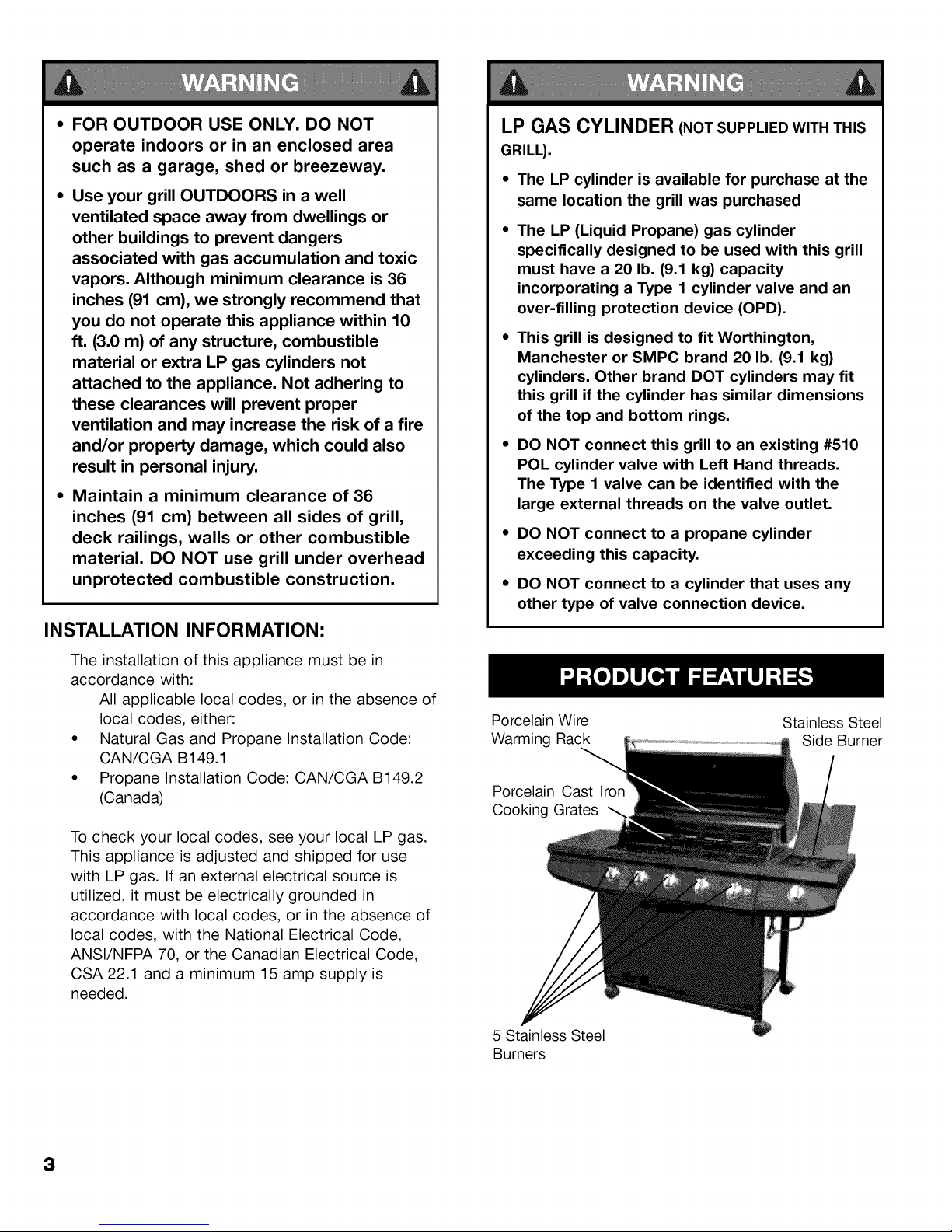
Porcelain Wire
Warming Rack
Porcelain Cast Iron
Cooking Grates
5 Stainless Steel
Burners
Stainless Steel
Side Burner
3
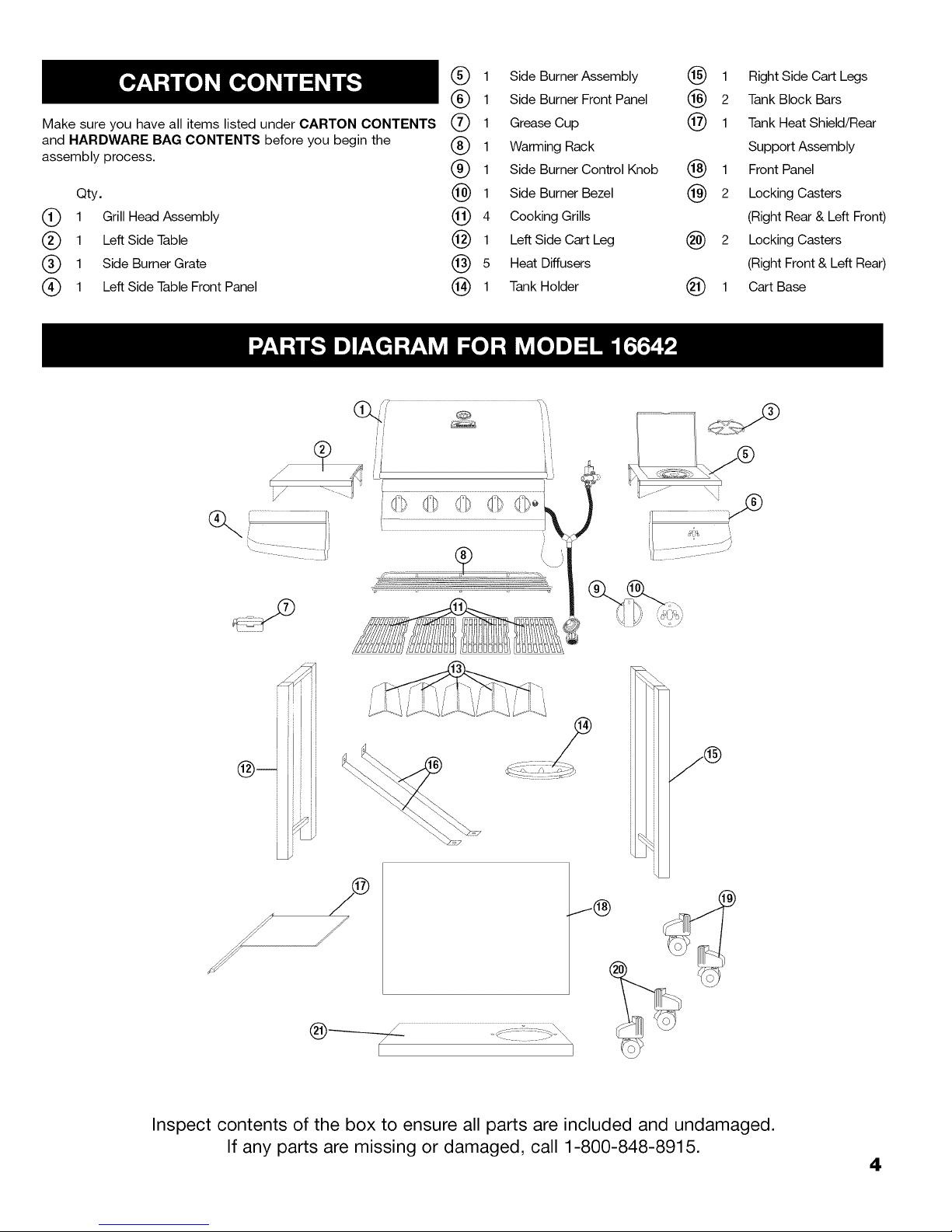
Make sure you have all items listed under CARTON CONTENTS
and HARDWARE BAG CONTENTS before you begin the
assembly process.
Qty.
(_ 1 Grill HeadAssembly
(_) 1 Left Side Table
(_ 1 Side Burner Grate
(_ 1 Left Side Table Front Panel
(_) 1
(_) 1
® 1
(_) 1
@4
(_ 1
@ 1
Side Burner Assembly (_) 1
Side Burner Front Panel (_) 2
Grease Cup @ 1
Warming Rack
Side Burner Control Knob (_) 1
Side Burner Bezel (_) 2
Cooking Grills
Left Side Cart Leg @ 2
Heat Diffusers
Tank Holder (_) 1
Right Side Cart Legs
Tank Block Bars
Tank HeatShield/Rear
Support Assembly
Front Panel
Locking Casters
(Right Rear & Left Front)
Locking Casters
(Right Front & Left Rear)
Cart Base
Inspect contents of the box to ensure all parts are included and undamaged.
If any parts are missing or damaged, call 1-800-848-8915.
4
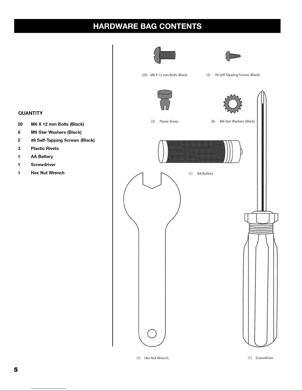
QUANTITY
20 M6 X 12 mm Bolts (Black)
8 M6 Star Washers (Black)
2 #8 Self-Tapping Screws (Black)
3 Plastic Rivets
1 AA Battery
1 Screwdriver
1 Hex Nut Wrench
(20) M6 X 12 mm Bolts (Black)
(3) Plastic Rivets
(2) #8 Self-Tapping Screws (Black)
(8) M6 Star Washers (Black)
(1) AABattery
5
(1) Hex Nut Wrench
(1) Screwdriver
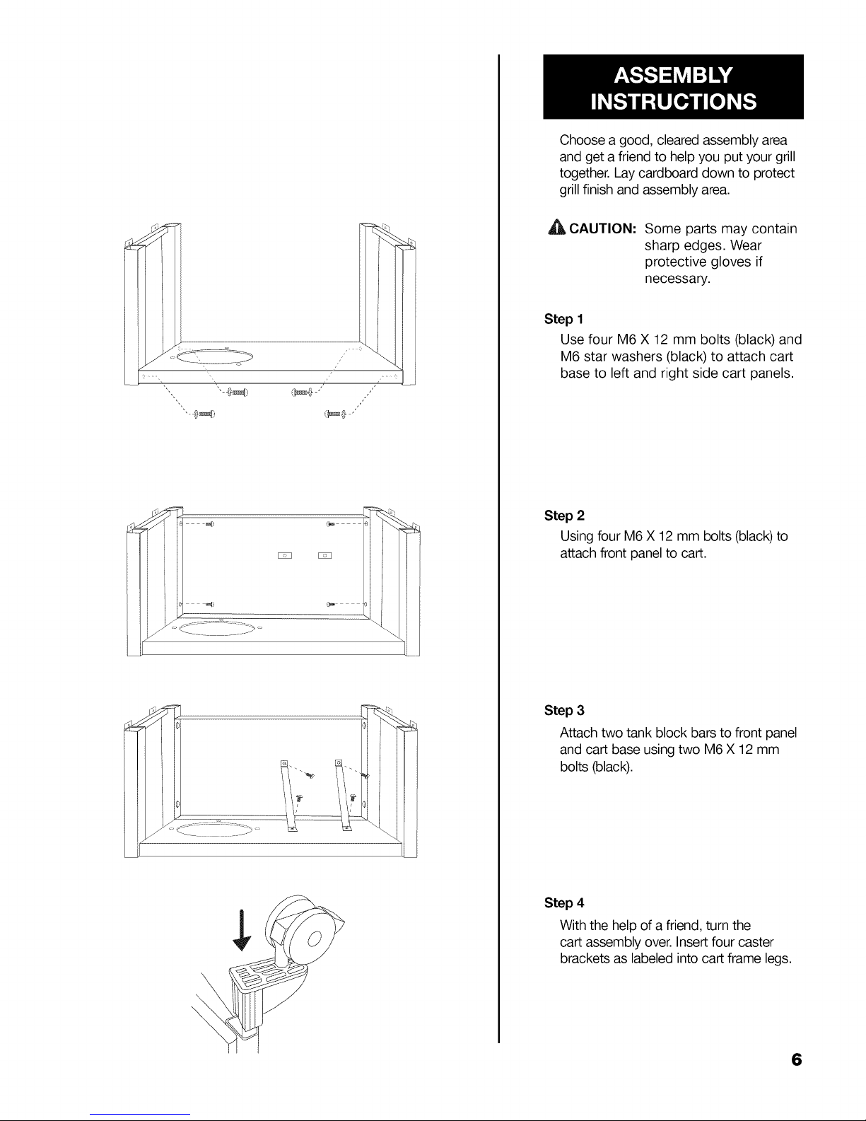
Choose a good, cleared assembly area
and get a friend to help you put your grill
together. Lay cardboard down to protect
grill finish and assembly area.
A'_ CAUTION:
Step 1
Use four M6 X 12 mm bolts (black) and
M6 star washers (black) to attach cart
base to left and right side cart panels.
Step 2
Using four M6 X 12 mm bolts (black)to
attach front panel to cart.
Some parts may contain
sharp edges. Wear
protective gloves if
necessary.
Step 3
Attach two tank block bars to front panel
and cart base using two M6 X 12 mm
bolts (black).
Step 4
With the help of afriend, turn the
cart assembly over. Insert four caster
brackets as labeled into cart frame legs.
6
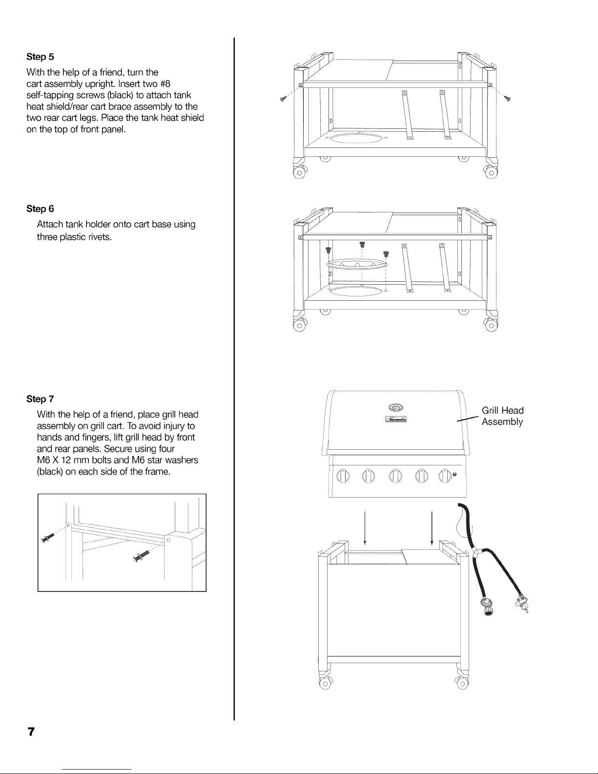
Step 5
With the help of a friend, turn the
cart assembly upright. Insert two #8
self-tapping screws (black) to attach tank
heat shield/rear cart brace assembly to the
two rear cart legs. Place the tank heat shield
on the top of front panel.
Step 6
Attach tank holder onto cart base using
three plastic rivets.
Step 7
With the help of a friend, place grillhead
assembly on grill cart. Toavoid injury to
hands and fingers, lift grill head by front
and rear _anels.Secure using four
M6 X 12 mm bolts and M6 star washers
(black) on each side of the frame.
ii
/i
ii
iA
Grill Head
-_J Assembly
'i
7
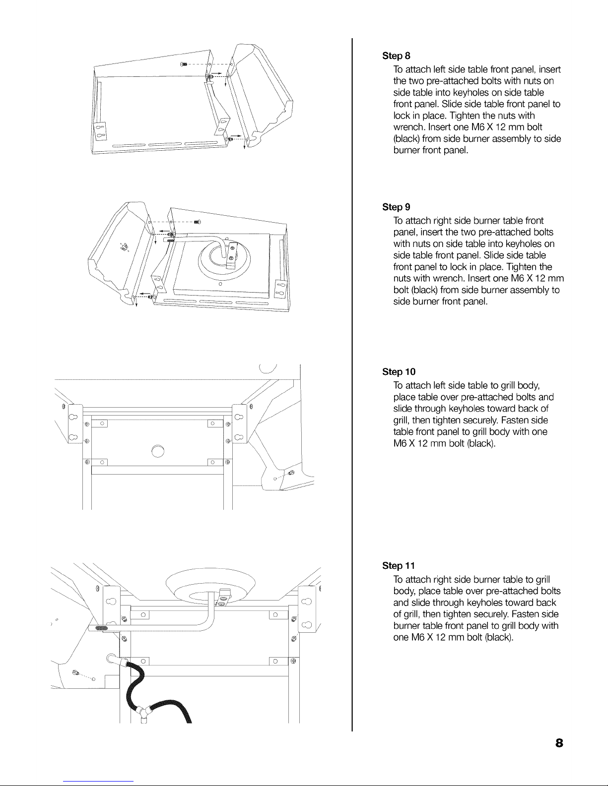
Step 8
Toattach left side table front panel, insert
the two pre-attached bolts with nuts on
side table into keyholes on side table
front panel. Slide side table front panel to
lock in place. Tighten the nuts with
wrench. Insert one M6 X 12 mm bolt
(black) from side burner assembly to side
burner front panel.
Step 9
Toattach right side burner table front
panel, insert the two pre-attached bolts
with nuts on side table into keyholes on
side table front panel. Slide side table
front panel to lock in place. Tighten the
nuts with wrench. Insert one M6 X 12mm
bolt (black)from side burner assembly to
side burner front panel.
oFo _
Step 10
Toattach left side table to grill body,
place table over pre-attached bolts and
slide through keyholes toward back of
grill,then tighten securely. Fasten side
table front panel to grill body with one
@
M6 X 12 mm bolt (black).
Step 11
Toattach right side burner table to grill
body, place table over pre-attached bolts
and slide through keyholes toward back
of grill, then tighten securely. Fasten side
burner table front panel to grill body with
one M6 X 12 mm bolt (black).
8
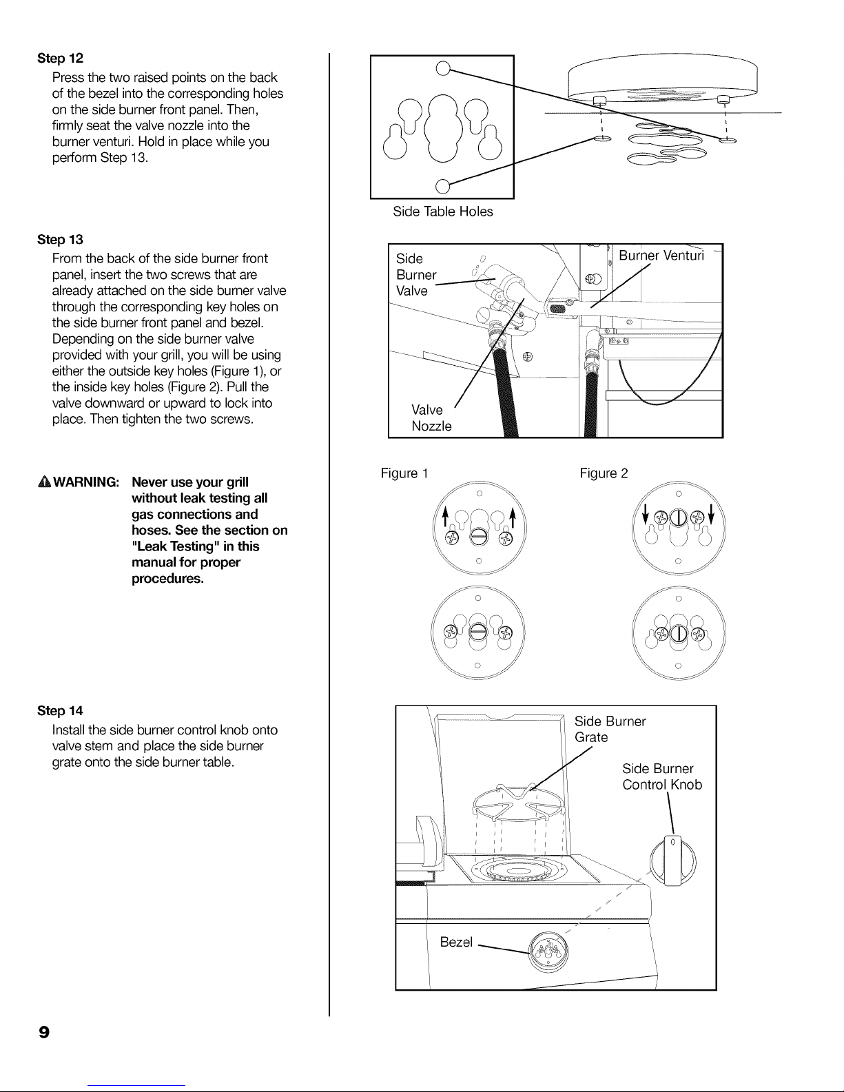
Step 12
Press the two raised points on the back
of the bezel into the corresponding holes
on the side burner front panel. Then,
firmly seat the valve nozzle into the
burner venturi. Hold in place while you
perform Step 13.
Step 13
From theback of the side burner front
panel, insertthe two screws that are
already attached on the side burner valve
through the corresponding key holes on
the side burner front panel and bezel.
Depending on the side burner valve
provided with your grill, you will be using
either the outside key holes (Figure 1),or
the inside key holes (Figure2). Pull the
valve downward or upward to lock into
place. Then tighten the two screws.
Side Table Holes
Side _.
Burner
Valve
Valve
Nozzle
£LWARNING:
Step 14
Installthe side burner control knob onto
valve stem and place the side burner
grate onto the side burner table.
Never use your grill
without leak testing all
gas connections and
hoses. See the section on
"Leak Testing" inthis
manual for proper
procedures.
Figure 1 Figure 2
Side Burner
Grate
Side Burner
Control Knob
9
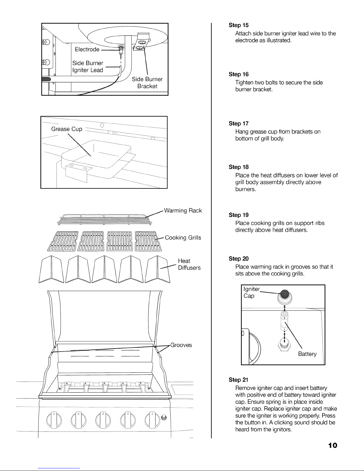
Step 15
Attach side burner igniter lead wire to the
electrode as illustrated.
Step 16
Tighten two bolts to secure the side
burner bracket.
Grease Cup
/Warming Rack
%
g Grills
Heat
Diffusers
Step 17
Hang grease cup from brackets on
bottom of grill body.
Step 18
Place the heat diffusers on lower level of
grill body assembly directly above
burners.
Step 19
Place cooking grills on support ribs
directly above heat diffusers.
Step 20
Place warming rack ingrooves so that it
sits above the cooking grills.
Igniter
Cap
Battery
Step 21
\
\
Remove igniter cap and insert battery
with positive end of battery toward igniter
cap. Ensure spring is in place inside
igniter cap. Replace igniter cap and make
sure the igniter is working properly. Press
the button in.A clicking sound should be
heard from the ignitors.
10
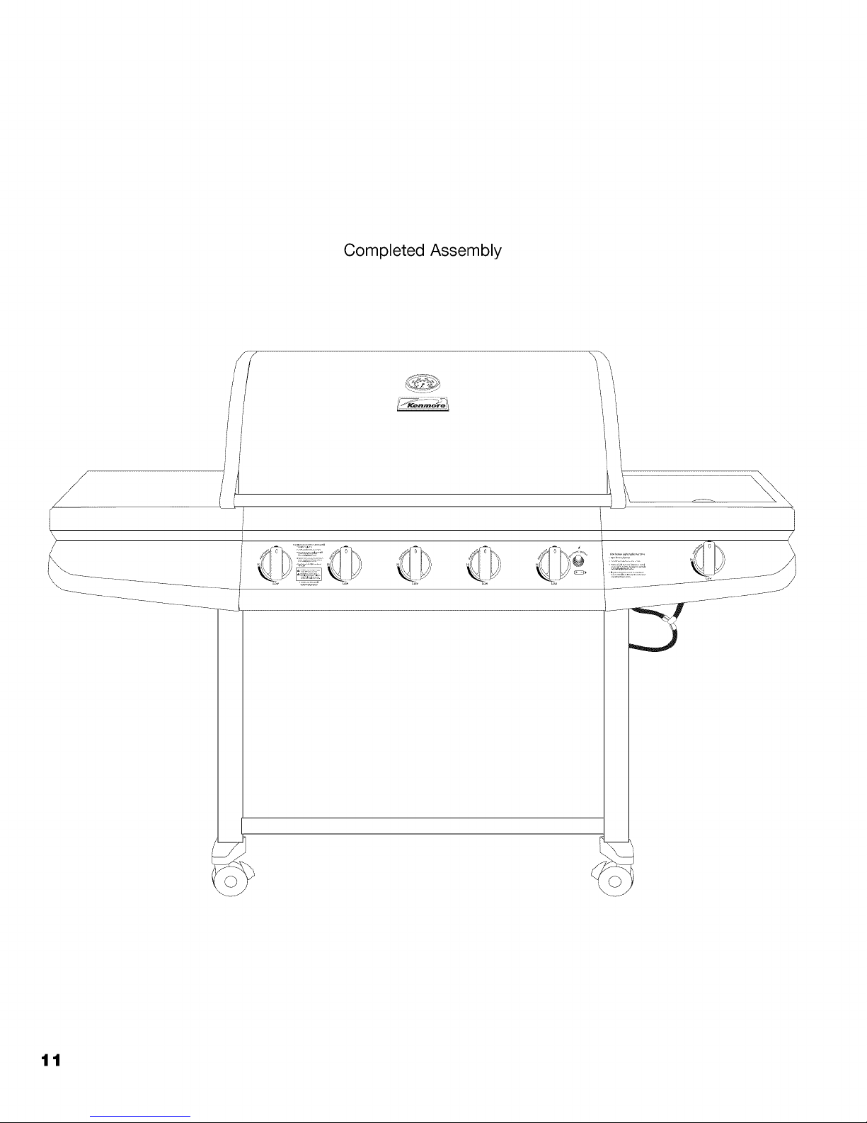
Completed Assembly
I
/
/
\
tt
When purchasing or exchanging a cylinder for your gas grill, it must
be constructed and marked in accordance with the specifications
for LP gas cylinders of the U.S. Department of Transportation (DOT)
or the National Standard of Canada, CAN/CSA-B339 Cylinders,
Spheres and Tubes for Transportation of Dangerous Goods; and
Commission, as applicable; and provided with a listed over-filling
prevention device (OPD), and provided with a cylinder connection
device compatible with the connection for outdoor cooking
appliances.
The cylinder must also be equipped with:
• A shut-off valve terminating in a Type 1 gas cylinder valve
outlet.
• A Type 1 valve that prevents gas flow until a positive seal
is obtained.
• An arrangement for vapor withdrawal.
• A collar to protect the cylinder shut-off valve.
• A safety relief device having direct communication with
the vapor space of the cylinder.
• A listed over-filling prevention device (OPD).
Turn off the cylinder valve when your grill is not in use.
• Handle the tank with care.
• Always secure the cylinder in an upright position.
• Never connect an unregulated LP gas cylinder to your
grill.
• DO NOT expose LP gas cylinders to excessive heat or
ignition sources.
• DO NOT store a spare LP gas cylinder under or near
your grill.
• Allow only qualified LP gas dealers to fill or repair your
LP gas cylinder.
• DO NOT allow the cylinder to be filled beyond 80%
capacity.
• Read and follow all warnings and instructions that are on
the cylinder and that accompany this product.
Never store a spare LP gas cylinder under or near your
grill. This could cause excess pressure to be expelled
through the vapor relief valve resulting in fire, explosion,
or severe personal injury including death.
Note: PROPANE GAS IS HEAVIER THAN AIR AND WILL
COLLECT IN LOW AREAS.PROPER VENTILATION
IS EXTREMELY IMPORTANT.
FILLING THE LP GAS CYLINDER:
Allow only qualified LP gas dealers to properly fill or
repair your LP gas cylinder.
New tanks should be purged prior to filling; inform LP
gas dealer if you are using a new tank.
DO NOT allow the cylinder to be filled beyond 80%
capacity. Over-filled tanks can create a dangerous
condition. Over-filled tanks can build-up pressure and
cause the relief valve to expel propane gas vapors. The
vapor is combustible and if it comes in contact with a
spark source or flame an explosion causing severe
burns, bodily harm, or death could occur.
The 20 Ib LP cylinder used with this smoker must
conform to the following requirements.
Diameter- 12" (30.5cm)
Height 18" (45.7cm)
With a maximum capacity of 20 pounds. The gas
cylinder used must include a collar to protect the
cylinder valve. The cylinder supply system must be
arranged for vapor withdrawal.
Place dust cap on cylinder valve outlet whenever the
cylinder is not in use. Only install the type of dust cap
on the cylinder valve outlet that is provided with the
cylinder valve, other types of caps or plugs may result
in leakage of propane.
If you exchange a cylinder with a qualified exchange
program, be sure the cylinder has a Type 1 valve and
an over-filling prevention device (OPD).
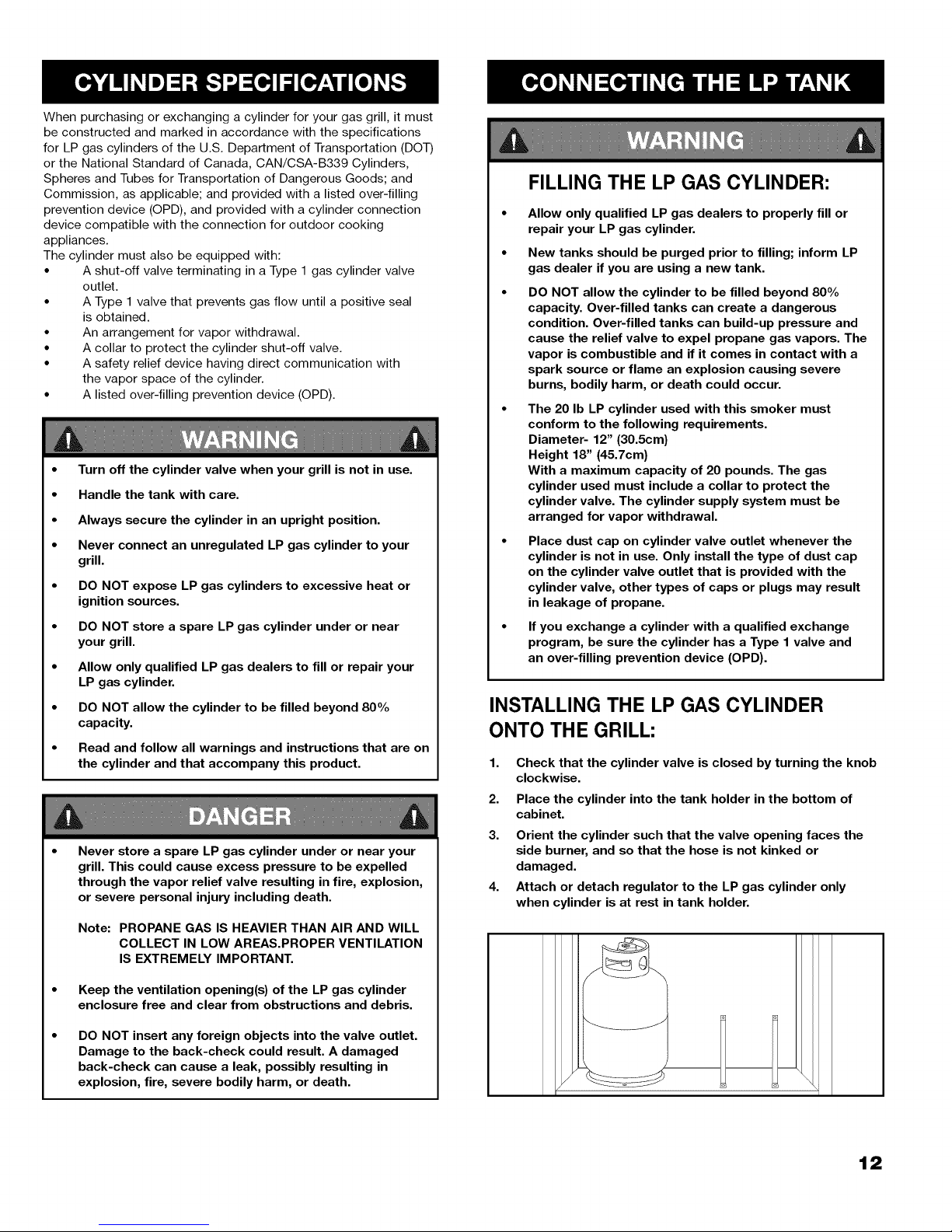
INSTALLING THE LP GAS CYLINDER
ONTO THE GRILL:
1.
Check that the cylinder valve is closed by turning the knob
clockwise.
2.
Place the cylinder into the tank holder in the bottom of
cabinet.
3.
Orient the cylinder such that the valve opening faces the
side burner, and so that the hose is not kinked or
damaged.
4.
Attach or detach regulator to the LP gas cylinder only
when cylinder is at rest in tank holder.
Keep the ventilation opening(s) of the LP gas cylinder
enclosure free and clear from obstructions and debris.
DO NOT insert any foreign objects into the valve outlet.
Damage to the back-check could result. A damaged
back-check can cause a leak, possibly resulting in
explosion, fire, severe bodily harm, or death.
t2
 Loading...