

Kenmore 11098752793, 11098752794 Owner’s Manual

24" Wide (61 cm)
LAUNDRY CENTER
Washer - Gas Dryer
CENTRO DE LAVANDERIA
de 24" (61 cm) de ancho
Lavadora - Secadora a gas
Model/Modelo 110.98752
J
A/_ ¸_ _ _
\
8533595 Sears Roebuck and Co., Hoffman Estates, IL 60179 U.S.A. www.sears.com

TABLEOF CONTENTS
WARRANTY
WARRANTY ..................................................................................... 2
WASHER/DRYER SAFETY ............................................................ 3
INSTALLATION INSTRUCTIONS .................................................. 5
Tools and Parts ............................................................................ 5
Alternate Parts .............................................................................. 5
Location Requirements ............................................................... 5
Drain System ................................................................................ 7
Electrical Requirements ................................................................ 7
Gas Supply Requirements ........................................................... 8
Venting Requirements .................................................................. 9
Install Leveling Legs ..................................................................... 9
Remove Foam Packing ............................................................. 10
Connect Drain Hose .................................................................. 10
Connect Inlet Hoses .................................................................. 10
Secure Drain Hose .................................................................... 11
Plan Vent System ...................................................................... 11
Install Vent System .................................................................... 13
Level Laundry Center ................................................................ 13
Make Gas Connection ............................................................... 14
Connect Vent ............................................................................. 14
Complete Installation ................................................................. 14
WASHER USE .............................................................................. 15
Starting Your Washer ................................................................ 15
Cycles ........................................................................................ 16
Rinse and Spin .......................................................................... 16
Drain and Spin ........................................................................... 16
Understanding Washer Cycles .................................................. 16
Normal Sounds .......................................................................... 17
LAUNDRY TIPS ............................................................................ 17
Loading ...................................................................................... 17
DRYER USE ................................................................................. 18
Starting Your Dryer .................................................................... 18
Stopping and Restarting ........................................................... 18
Loading ...................................................................................... 18
Drying, Cycle and Temperature Tips ........................................ 19
Cycles ........................................................................................ 19
LAUNDRY CENTER CARE ......................................................... 20
Cleaning the Laundry Center Location ..................................... 20
Cleaning Your Washer ............................................................... 20
Water Inlet Hoses ...................................................................... 20
Cleaning the Lint Screen ........................................................... 20
Cleaning the Dryer Interior ........................................................ 21
Removing Accumulated Lint ..................................................... 21
Vacation, Storage, and Moving Care ........................................ 21
TROUBLESHOOTING WASHER ................................................ 22
TROUBLESHOOTING DRYER .................................................... 24
PROTECTION AGREEMENTS .................................................... 25
SERVICE NUMBERS ............................................... BACK COVER
Full One-Year Warranty on Mechanical and Electrical Parts
For one year from the date of purchase, when this laundry center
is installed and operated according to the instructions provided in
this Use and Care Guide, Sears will repair this laundry center, free
of charge, if defective in material or workmanship.
NOTE: Exhausting your laundry center with a plastic vent can
void this warranty. See "Installation Instructions" for the complete
exhaust requirements for this laundry center.
Limited Five-Year Warranty on Gearcase Parts
For the second through fifth years from the date of purchase,
Sears will replace any gearcase parts that are defective in
material or workmanship. You will be charged for labor after the
first year.
Limited Ten-Year Warranty on Plastic Tub
For the second through tenth years from the date of purchase,
Sears will replace the plastic tub if defective in material or
workmanship. You will be charged for labor after the first year.
Warranty Restriction
If the laundry center is subject to other than private family use,
the above warranty coverage is effective for only 90 days.
Warranty Service
Warranty service is available by contacting the nearest Sears
Service Center. This warranty applies only while the product is in
use in the United States.
This warranty gives you specific legal rights and you may also
have other rights which vary from state to state.
For Sears warranty information or to contact a Sears Service
Center, please reference the service numbers located on the
back page of this manual.
Sears, Roebuck and Co.
D/817WA, Hoffrnan Estates, IL60179
Product Record
In the space below, record your complete model number, serial
number, and purchase date. You can find this information on the
model and serial number label, located at the top inside dryer
door well.
Have this information available to help you quickly obtain
assistance or service when you contact Sears concerning your
appliance.
Model number
Serial number
Purchase date
Save these instructions and your sales receipt for future
reference.
WASHER/DRYER SAFETY
Your safety and the safety of others are very important.
We have provided many important safety messages in this manual and on your appliance. Always read and obey all safety
messages.
This is the safety alert symbol.
This symbol alerts you to potential hazards that can kill or hurt you and others.
All safety messages will follow the safety alert symbol and either the word "DANGER" or "WARNING."
These words mean:
You can be killed or seriously injured if you don't immediately
follow instructions.
You can be killed or seriously injured if you don't follow
instructions.
All safety messages will tell you what the potential hazard is, tell you how to reduce the chance of injury, and tell you what can
happen if the instructions are not followed.
i WARNING: For your safety, the information in this manual must be followed to minimize
the risk of fire or explosion, or to prevent property damage, personal injury, or death.
- Do not store or use gasoline or other flammable vapors and liquids in the vicinity of this
or any other appliance.
- WHAT TO DO IF YOU SMELL GAS:
• Do not try to light any appliance.
• Do not touch any electrical switch; do not use any phone in your building.
• Clear the room, building, or area of all occupants.
• Immediately call your gas supplier from a neighbor's phone. Follow the gas supplier's
instructions.
• If you cannot reach your gas supplier, call the fire department.
- Installation and service must be performed by a qualified installer, service agency, or
the gas supplier.
In the State of Massachusetts, the following installation instructions apply:
,= Installations and repairs must be performed by a qualified or licensed contractor, plumber, or gasfitter qualified or licensed by
the State of Massachusetts.
,= If using a ball valve, it shall be a T-handle type.
,= A flexible gas connector, when used, must not exceed 3 feet.
iMPORTANT SAFETY iNSTRUCTiONS
WARNUNG: To reduce the risk of fire, electric shock, or injury to persons when using the washer/dryer, follow basic
precautions, including the fotlowing:
Read all instructions before using the washer/dryer.
Do not place items exposed to cooking oils in your dryer.
Items contaminated with cooking oils may contribute to a
chemical reaction that could cause a Ioad to catch fire.
Do not wash or dry articles that have been previously
cleaned in, washed in, soaked in, or spotted with gasoline,
dry-cleaning solvents, other flammable, or explosive
substances as they give off vapors that could ignite or
explode.
Do not add gasoline, dry-cleaning solvents, or other
flammable, or explosive substances to the wash water.
These substances give off vapors that could ignite or
explode.
Do not allow children to play on or in the washer/dryer.
Close supervision of children is necessary when the
washer/dryer is used near children.
Before the washer/dryer is removed from service or
discarded, remove the doors to the washer/dryer
compartments.
Do not reach into the washer/dryer if the tub, agitator or
drum is moving.
Do not install or store the washer/dryer where it will be
exposed to the weather.
Do not tamper with controls.
Clean dryer lint screen before or after each load.
SAVE THESE iNSTRUCTiONS
Under certain conditions, hydrogen gas may be produced
in a hot water system that has not been used for 2 weeks
or more. HYDROGEN GAS IS EXPLOSIVE. If the hot water
system has not been used for such a period, before using
the washing machine, turn on all hot water faucets and let
the water flow from each for several minutes. This will
release any accumulated hydrogen gas. As the gas is
flammable, do not smoke or use an open flame during this
time.
Do not repair or replace any part of the washer/dryer or
attempt any servicing unless specifically recommended in
this Use and Care Guide or in published user-repair
instructions that you understand and have the skills to
carry out.
Do not use fabric softeners or products to eiiminate static
unless recommended by the manufacturer of the fabric
softener or product.
Do not use heat to dry articles containing foam rubber or
sirnilariy textured rubber-like materials.
Keep area around the exhaust opening and adjacent
surrounding areas free from the accumulation of lint, dust,
and dirt.
The interior of the machine and dryer exhaust vent should
be cleaned periodica!ly by qualified service personnel.
See "Electrical Requirements" for grounding instructions.
IMPORTANT: The gas installation must conform with local codes, or in the absence of local codes, with the National Fuel Gas
Code, ANSI Z223,1/NFPA 54,
The dryer must be electricaily grounded in accordance with local codes, or in the absence of local codes, with the National
Electrical Code, ANSI/NFPA 70,
INSTALLATION INSTRUCTIONS
Check that you have everything necessary for correct installation.
Proper installation is your responsibility.
Tools needed:.
8" or 10" adjustable • Knife
wrench (for gas
connections) • Vent clamps
Flat-blade screwdriver • Pipe-joint compound
resistant to L.R gas
Adjustable wrench that
opens to 1" (2.5 cm) or • Caulking gun and
9/16"(14 mm) open-end compound (for installing
wrench (for adjusting new exhaust vent)
dryer feet) • Pliers
Level • Ruler or measuring tape
1A"nut driver or socket • Tin snips (new vent
wrench installation)
• Wood block (for leveling)
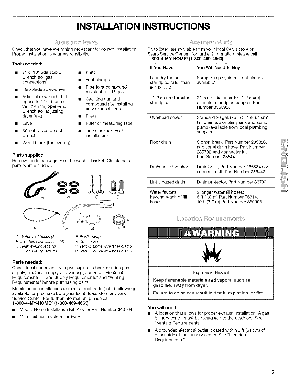
Parts supplied:
Remove parts package from the washer basket. Check that all
parts were included.
Parts listed are available from your local Sears store or
Sears Service Center. For further information, please call
1-800-4-MY-HOME® (1-800-469-4663)
If You Have You Will Need to Buy
Laundry tub or Sump pump system (if not already
standpipe taller than available)
96" (2.4 m)
1" (2.5 cm) diameter 2" (5 cm) diameter to 1" (2.5 cm)
standpipe diameter standpipe adapter, Part
Number 3363920
Overhead sewer Standard 20 gal. (76 L) 34" (86.4 cm)
tall drain tub or utility sink and sump
pump (available from local plumbing
suppliers)
Floor drain Siphon break, Part Number 285320,
additional drain hose, Part Number
285702 and connector kit,
Part Number 285442
Drain hose too short Drain hose, Part Number 285664 and
connector kit, Part Number 285442
Lint clogged drain Drain protector, Part Number 367031
C D
A. Water inlet hoses (2)
B. Inlet hose flat washers (4)
C. Rear leveling legs (2)
D. Front leveling legs (2)
Parts needed:
Check local codes and with gas supplier, check existing gas
supply, electrical supply and venting, and read "Electrical
Requirements," "Gas Supply Requirements" and "Venting
Requirements" before purchasing parts.
Mobile home installations require special parts (listed following)
available for purchase from your local Sears store or Sears
Service Center. For further information, please call
1-800-4-MY-HOME ®(1-800-469-4663).
• Mobile Home Installation Kit. Ask for Part Number 346764.
• Metal exhaust system hardware.
E. Plastic strap
F Drain hose
G. Yellow, single wire hose clamp
H. Silver, double wire hose clamp
Water faucets 2 longer water fill hoses:
beyond reach of fill 6 ft (1.8 m) Part Number 76314,
hoses 10 ft (3.0 m) Part Number 350008
Exp(osion Hazard
Keep flammable materia(s and vapors, such as
gasoline, away from dryer.
Fai(ure to do so can result in death, explosion, or fire.
You will need
• A location that allows for proper exhaust installation. A gas
laundry center must be exhausted to the outdoors. See
"Venting Requirements."
• A grounded electrical outlet located within 2ft (61 cm) of
either side of the laundry center. See "Electrical
Requirements."
• Asturdyfloortosupportthelaundrycenterweight(laundry
center,waterandload)of500Ibs(226.8kg).
Alevelfloorwithamaximumslopeof1"(2.5cm)underentire
laundrycenter.Clothesmaynottumbleproperlyand
automaticsensorcyclesmaynotoperatecorrectlyiflaundry
centerisnotlevel.Installingoncarpetisnotrecommended.
• Awaterheatersettodeliver120°F(49°C)watertothe
washer.
• Hotandcoldwaterfaucetslocatedwithin4ft(1.2m)of
thehotandcoldwaterfillvalves,andwaterpressureof
5-100psi(34.5-689.6kPa).
Thelaundrycentermustnotbeinstalledorstoredinanarea
whereitwillbeexposedtowaterand/orweather.
Donotoperateyourwasherintemperaturesatorbelow
32°F(0°C).Somewatercanremaininthewasherandcan
causedamageinlowtemperatures.See"Vacation,Storage,and
MovingCare"forwinterizinginformation.
Donotoperateyourdryerattemperaturesbelow45°F(7°C).At
lowertemperatures,thedryermightnotshutoffattheendofan
automaticcycle.Thiscanresultinlongerdryingtimes.
Checkcoderequirements.Somecodeslimit,ordonotpermit,
installationofthelaundrycenteringarages,closets,mobile
homes,orsleepingquarters.Contactyourlocalbuilding
inspector.
NOTE:Nootherfuel-burningappliancecanbeinstalledinthe
sameclosetasadryer.
Installation Clearances
The location must be large enough to fully open the dryer door.
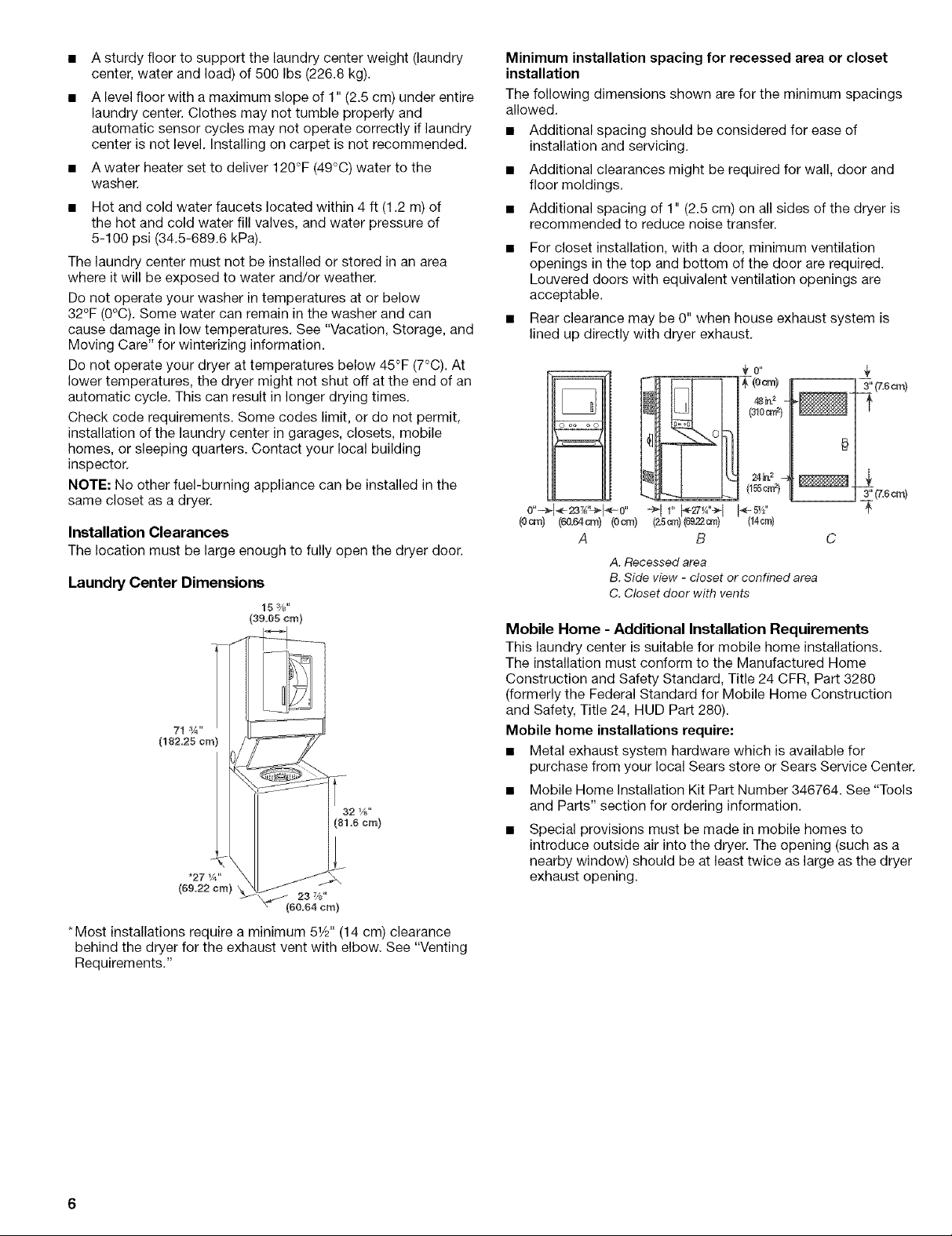
Laundry Center Dimensions
15 3/,_"
(39.05 cm)
71:¼"
(182.25 cm)
*27 _A"
(69.22 cm}
Minimum installation spacing for recessed area or closet
installation
The following dimensions shown are for the minimum spacings
allowed.
• Additional spacing should be considered for ease of
installation and servicing.
• Additional clearances might be required for wall, door and
floor moldings.
• Additional spacing of 1" (2.5 cm) on all sides of the dryer is
recommended to reduce noise transfer.
For closet installation, with a door, minimum ventilation
openings in the top and bottom of the door are required.
Louvered doors with equivalent ventilation openings are
acceptable.
• Rear clearance may be 0" when house exhaust system is
lined up directly with dryer exhaust.
o oo o o
0"=-_(<-23_'L>1÷0'' i_-5Y_"
(0cm) (_0._om) (0®) (_4¢rr_)
A C
Mobile Home - Additional Installation Requirements
This laundry center is suitable for mobile home installations.
The installation must conform to the Manufactured Home
Construction and Safety Standard, Title 24 CFR, Part 3280
(formerly the Federal Standard for Mobile Home Construction
and Safety, Title 24, HUD Part 280).
Mobile home installations require:
• Metal exhaust system hardware which is available for
purchase from your local Sears store or Sears Service Center.
• Mobile Home Installation Kit Part Number 346764. See "Tools
and Parts" section for ordering information.
Special provisions must be made in mobile homes to
introduce outside air into the dryer. The opening (such as a
nearby window) should be at least twice as large as the dryer
exhaust opening.
(z5®) (s9.22®)
B
A. Recessed area
B. Side view - closet or confined area
C. Closet door with vents
*Most installations require a minimum 51/2'' (14 cm) clearance
behind the dryer for the exhaust vent with elbow. See "Venting
Requirements."
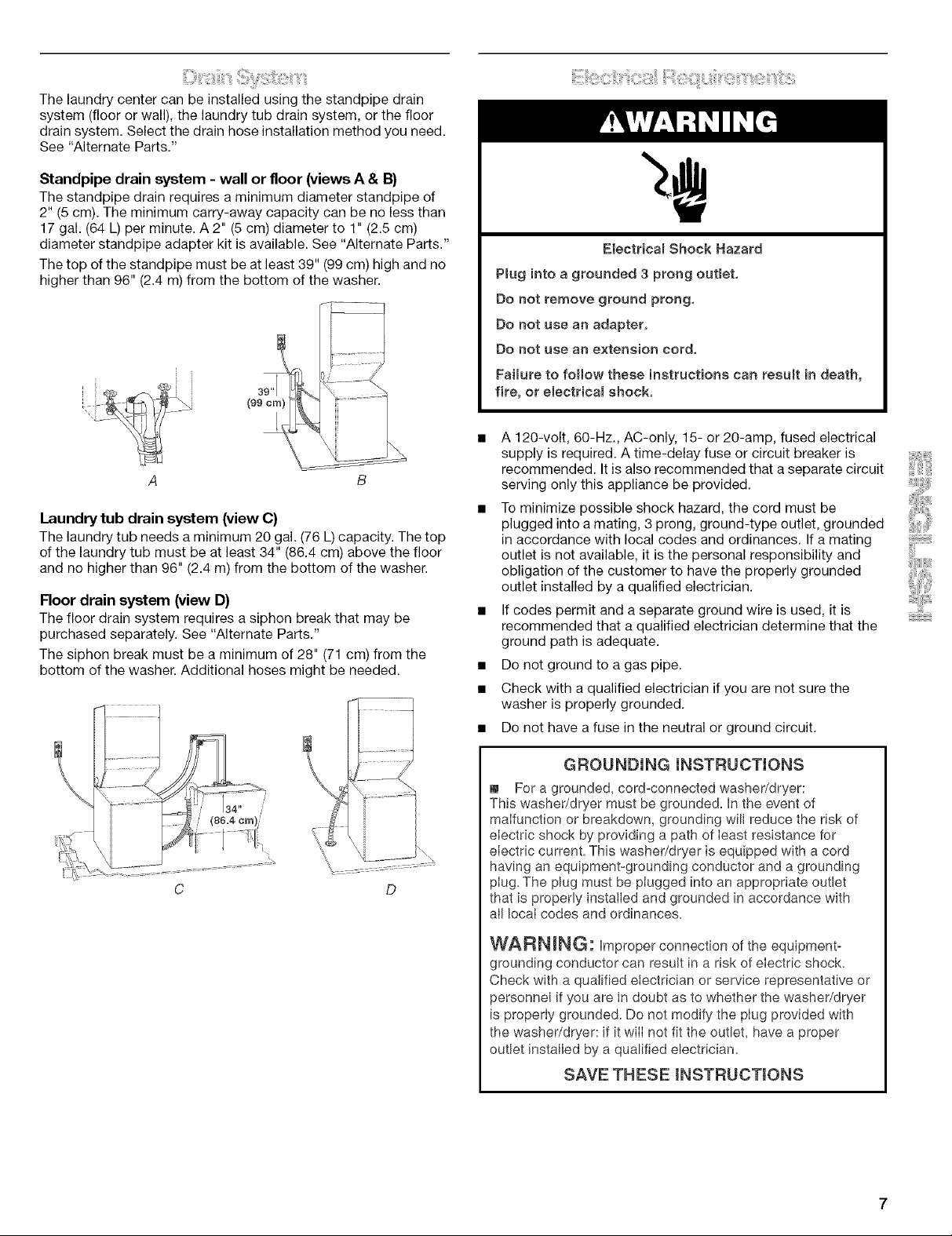
Thelaundrycentercanbeinstalledusingthestandpipedrain
system(floororwall),thelaundrytubdrainsystem,orthefloor
drainsystem.Selectthedrainhoseinstallationmethodyouneed.
See"AlternateParts,"
Standpipe drain system - wall or floor (views A & 13}
The standpipe drain requires a minimum diameter standpipe of
2" (5 cm). The minimum carry-away capacity can be no less than
17 gal. (64 L) per minute. A 2" (5 cm) diameter to 1" (2.5 cm)
diameter standpipe adapter kit is available. See "Alternate Parts."
The top of the standpipe must be at least 39" (99 cm) high and no
higher than 96" (2.4 m) from the bottom of the washer.
A B
Laundry tub drain system (view C)
The laundry tub needs a minimum 20 gal. (76 L) capacity. The top
of the laundry tub must be at least 34" (86.4 cm) above the floor
and no higher than 96" (2.4 m) from the bottom of the washer.
Floor drain system (view D)
The floor drain system requires a siphon break that may be
purchased separately, See "Alternate Parts,"
The siphon break must be a minimum of 28" (71 cm) from the
bottom of the washer. Additional hoses might be needed.
Electricam Shock Hazard
Pmug into a grounded 3 prong outmet,
Do not remove ground prong,
Do not use an adapter,
Do not use an extension cord,
FaiBure to follow these instructions can resumt in death,
fire, or eiectricam shock,
A 120-volt, 60-Hz., AC-only, 15- or 20-amp, fused electrical
supply is required. A time-delay fuse or circuit breaker is
recommended. It is also recommended that a separate circuit
serving only this appliance be provided,
To minimize possible shock hazard, the cord must be
plugged into a mating, 3 prong, ground-type outlet, grounded
in accordance with local codes and ordinances, If a mating
outlet is not available, it is the personal responsibility and
obligation of the customer to have the properly grounded
outlet installed by a qualified electrician.
If codes permit and a separate ground wire is used, it is
recommended that a qualified electrician determine that the
ground path is adequate.
Do not ground to a gas pipe.
Check with a qualified electrician if you are not sure the
washer is properly grounded,
• Do not have a fuse in the neutral or ground circuit.
GROUNDmNG mNSTRUCTIONS
[] For a grounded, cord-connected washer/dryer:
This washer/dryer must be grounded. In the event of
malfunction or breakdown, grounding will reduce the risk of
electric shock by providing a path of least resistance for
electric current. This washer/dryer is equipped with a cord
having an equipment-grounding conductor and a grounding
D
plug. The plug must be plugged into an appropriate outlet
that is properly installed and grounded in accordance with
alI local codes and ordinances.
WARNING: Improper connection of the equipment-
grounding conductor can result in a risk of electric shock.
Check with a qualified electrician or service representative or
personnel if you are in doubt as to whether the washer/dryer
is properly grounded. Do not modify the plug provided with
the washer/dryer: if it wilI not fit the outlet, have a proper
outlet installed by a qualified electrician.
SAVE THESE INSTRUCTIONS
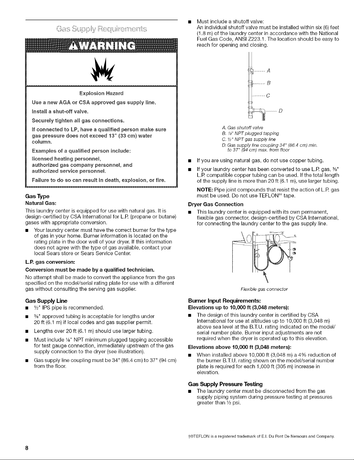
Must include a shutoff valve:
An individual shutoff valve must be installed within six (6) feet
(1.8 m) of the laundry center in accordance with the National
Fuel Gas Code, ANSI Z223.1. The location should be easy to
reach for opening and closing.
................................A
.............................B
ExpBosion Hazard
Use a new AGA or CSA approved gas suppmy line.
_nstaH a shut=off vamve.
Securemy tighten aH gas connections.
ff connected to LP, have a qualified person make sure
gas pressure does not exceed 13" (33 cm) water
coJumn.
Examples of a qualified person incmude:
micensed heating personnel
authorized gas company personnel, and
authorized service personnel
Faimureto do so can resumt in death, explosion, or fire.
Gas Type
Natural Gas:
This laundry center is equipped for use with natural gas. It is
design-certified by CSA International for L.R (propane or butane)
gases with appropriate conversion.
• Your laundry center must have the correct burner for the type
of gas in your home. Burner information is located on the
rating plate in the door well of your dryer. If this information
does not agree with the type of gas available, contact your
local Sears store or Sears Service Center.
L.P. gas conversion:
Conversion must be made by a qualified technician.
No attempt shall be made to convert the appliance from the gas
specified on the model/serial rating plate for use with a different
gas without consulting the serving gas supplier.
.................................C
A. Gas shutoff valve
B. _" NPT plugged tapping
C. Y;" NPT gas supply line
D. Gas supply line coupling 34" (86.4 cm) min.
to 37" (94 cm) max. from floor
• If you are using natural gas, do not use copper tubing.
• If your laundry center has been converted to use L.R gas, %"
L.R compatible copper tubing can be used. Ifthe total length
of the supply line is more than 20 ft (6.1 m), use larger tubing.
NOTE: Pipe joint compounds that resist the action of L.R gas
must be used. Do not use TEFLON _ttape.
Dryer Gas Connection
• This laundry center is equipped with its own permanent,
flexible gas connector, design-certified by CSA International,
for connecting the laundry center to the gas supply line.
Flexiblegas connector
Gas Supply Line
• r/2" IPS pipe is recommended.
• %" approved tubing is acceptable for lengths under
20 ft (6.1 m) if local codes and gas supplier permit.
• Lengths over 20 ft (6.1 m) should use larger tubing.
• Must include 1/8"NPT minimum plugged tapping accessible
for test gauge connection, immediately upstream of the gas
supply connection to the dryer (see illustration).
• Gas supply line coupling must be 34" (86.4 cm) to 37" (94 cm)
from the floor.
Burner Input Requirements:
Elevations up to 10,000 ft (3,048 meters):
• The design of this laundry center is certified by CSA
International for use at altitudes up to 10,000 ft (3,048 m)
above sea level at the B.T.U. rating indicated on the model/
serial number plate. Burner input adjustments are not
required when the dryer is operated up to this elevation.
Elevations above 10,000 ft (3,048 meters):
• When installed above 10,000 ft (3,048 m) a 4% reduction of
the burner B.T.U. rating shown on the model/serial number
plate is required for each 1,000 ft (305 m) increase in
elevation.
Gas Supply Pressure Testing
• The laundry center must be disconnected from the gas
supply piping system during pressure testing at pressures
greater than 1/2psi.
1-®TEFLON is a registered trademark of E.I. Du Pont De Nemours and Company.
Fire Hazard
Use a heavy metal vent.
Do not use a ptastic vent.
Do not use a metal foimvent.
Failure to follow these instructions can resumt in death
or fire.
WARNING: To reduce the risk of fire, this laundry center
MUST BE EXHAUSTED OUTDOORS.
4" (10.2 cm) heavy metal exhaust vent and clamps must be used.
DURASAFE TMventing products are recommended and are
available from your local Sears store or Sears Service Center.
DURASAFE TMvent products can be purchased from your dealer.
For further information, please call 1-800-4-MY-HOME ®
(1-800-469-4663) or visit our Internet site at www.sears.com.
• The dryer exhaust must not be connected into any gas vent,
chimney, wall, ceiling, or a concealed space of a building.
Do not use an exhaust hood with a magnetic latch.
Do not install flexible metal vent in enclosed walls, ceilings or
floors.
Use clamps to seal all joints. Exhaust vent must not be
connected or secured with screws or other fastening devices
which extend into the interior of the duct. Do not use duct
tape.
IMPORTANT: Observe all governing codes and ordinances.
Excessive Weight Hazard
Use two or more people to move and install
washer/dryer.
Failure to do so can result in back or other injury.
To protect the floor, use a large flat piece of cardboard from the
shipping carton. Gently place the laundry center on its side, on
the cardboard.
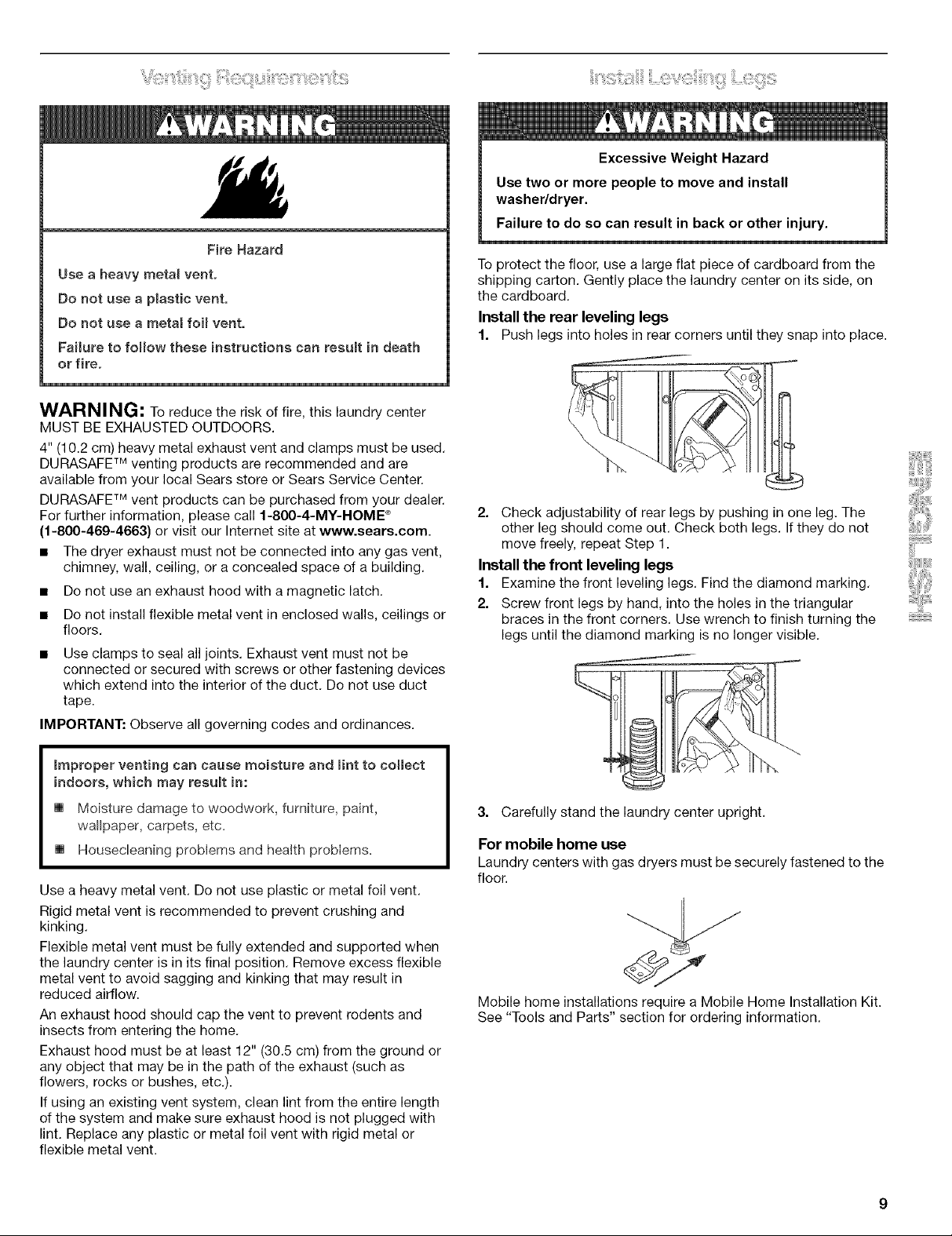
Install the rear leveling legs
1. Push legs into holes in rear corners until they snap into place.
2. Check adjustability of rear legs by pushing in one leg. The
other leg should come out. Check both legs. If they do not
move freely, repeat Step 1.
Install the front leveling legs
1. Examine the front leveling legs. Find the diamond marking.
2. Screw front legs by hand, into the holes in the triangular
braces in the front corners. Use wrench to finish turning the
legs until the diamond marking is no longer visible.
improper venting can cause moisture and mintto collect
indoors, which may resumt in:
[] Moisture damage to woodwork, furniture, paint,
wallpaper, carpets, etc.
[] Housecleaning problems and health problems.
Use a heavy metal vent. Do not use plastic or metal foil vent.
Rigid metal vent is recommended to prevent crushing and
kinking.
Flexible metal vent must be fully extended and supported when
the laundry center is in its final position. Remove excess flexible
metal vent to avoid sagging and kinking that may result in
reduced airflow.
An exhaust hood should cap the vent to prevent rodents and
insects from entering the home.
Exhaust hood must be at least 12" (30.5 cm) from the ground or
any object that may be in the path of the exhaust (such as
flowers, rocks or bushes, etc.).
If using an existing vent system, clean lint from the entire length
of the system and make sure exhaust hood is not plugged with
lint. Replace any plastic or metal foil vent with rigid metal or
flexible metal vent.
3. Carefully stand the laundry center upright.
For mobile home use
Laundry centers with gas dryers must be securely fastened to the
floor.
Mobile home installations require a Mobile Home Installation Kit.
See "Tools and Parts" section for ordering information.

1. Openthewasherlid.Thelatchunderthedryerwillkeepthe
lidopen.
2. Pullthefoampackingringoutofthewasher.
NOTE:Keepthefoamringanduseitwhentransportingyour
laundrycenter.Thispackingmaterialisusedtokeepthewasher
tubstableduringtransport.
Properconnectionofthedrainhoseprotectsyourfloorsfrom
damageduetowaterleakage.Topreventthedrainhosefrom
comingofforleaking,itmustbeinstalledaccordingtothe
followinginstructions:
IMPORTANT:Toensureproperinstallation,thisproceduremust
befollowedexactly.
1. Checkthedrainhosetoseewhetheritistheproperlength.
2. Wettheinsideofthestraightendofthedrainhosewithtap
water.
IMPORTANT: Do not use any lubricant other than water.
3. Squeeze ears of the silver, double-wire clamp with pliers to
open. Place clamp over the straight end of the drain hose
1A"(6.4 mm) from the end.
For laundry tub or standpipe drain systems
1. Open the yellow, single-wire clamp and slide over the hooked
end of the drain hose to secure the rubber and corrugated
sections together.
A. Hooked end
B. Drain hose
2. Put the hooked end of drain hose into laundry tub or
standpipe. Rotate hook to eliminate kinks.
To prevent drain water from going back into the washer:
• Do not straighten hooked end of the drain hose and force
excess drain hose into standpipe. Hose should be secure but
loose enough to provide a gap for air.
• Do not lay excess hose on the bottom of the laundry tub.
For use with floor drain
Remove the drain hose hook from the corrugated drain hose. You
may need additional parts. See "Floor drain" under "Alternate
Parts."
1. Insert a new flat washer (supplied) into each end of the inlet
hoses. Firmly seat the washers in the couplings.
4.
Open clamp. Twist hose back and forth while pushing onto
drain connector on the side of the laundry center. Continue
until hose contacts the ribbed stops on the cabinet.
\
\
\
\
\
5. Place clamp over the area marked "CLAMR" Release clamp.
A B
A. Coupling
B. Washer
Connect the inlet hoses to the water faucets
Make sure the washer basket is empty.
2. Attach the hose with the red coupling to the hot water faucet.
Screw on coupling by hand until it is seated on the washer.
3. Attach the hose with the blue coupling to the cold water
faucet. Screw on coupling by hand until it is seated on the
washer.
4. Using pliers, tighten the couplings with an additional two-
thirds turn.
J
NOTE: Do not overtighten. Damage to the valves can result.
10
Clear the water lines
5. Run water through both faucets and inlet hoses, into a bucket
or laundry tub, to get rid of particles in the water lines that
might clog the inlet valve screens.
Connect the inlet hoses to the washer
6. Attach the hose with the blue coupling to the cold water (top)
inlet valve. Screw on coupling by hand until it is seated on the
washer. Using pliers, tighten the couplings with an additional
two-thirds turn.
NOTE: Do not overtighten. Damage to the valves can result.
B
1.
Move the laundry center to its final location and remove any
cardboard used to move the laundry center.
2.
Locate the plastic strap included in the parts package.
CZ>
Beaded tie strap
3. Wrap the drain hose to the laundry tub leg or standpipe with
the plastic strap (A or B below) and secure.
A. Cold water inlet valve (blue)
B. Hot water inlet valve (red)
7. Attach the hose with the red coupling to the hot water
(bottom) inlet valve. Screw on coupling by hand until it is
seated on the washer. Using pliers, tighten the couplings with
an additional two-thirds turn.
NOTE: Do not overtighten. Damage to the valves can result.
If you are working in a closet or recessed area
Move the laundry center into its final position and remove
cardboard from under laundry center. Remove the access panel
by removing 3 Phillips-head screws and one bumper, located at
the top of the access panel. Set panel, screws, and bumper
aside. Complete hookup of water hoses and (on gas models) the
flexible gas connector through the access area. Replace access
panel upon completion of laundry center installation.
Check for leaks
8. Turn on the water faucets and check for leaks. A small
amount of water might enter the washer. You will drain this
later.
NOTE: Replace inlet hoses after 5 years of use to reduce the risk
of hose failure. Record hose installation or replacement dates for
future reference.
• If you connect only one water hose, you must cap off the
remaining water inlet port.
• Periodically inspect and replace hoses if bulges, kinks, cuts,
wear, or leaks are found.
A B C
If the water faucets and the drain standpipe are recessed, put
the hooked end of the drain hose inthe standpipe. Tightly
wrap the plastic strap around the water inlet hoses and the
drain hose (C above).
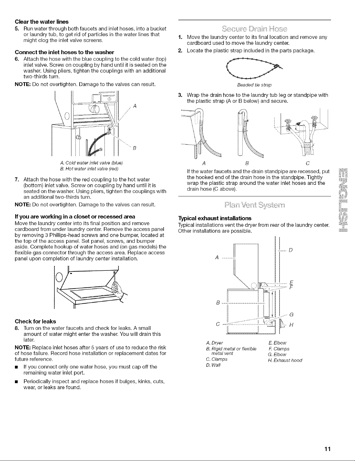
Typical exhaust installations
Typical installations vent the dryer from rear of the laundry center.
Other installations are possible.
A. Dryer E. Elbow
B. Rigid metal or flexible E Clamps
metal vent G. Elbow
C. Clamps H. Exhaust hood
D. Wall
11
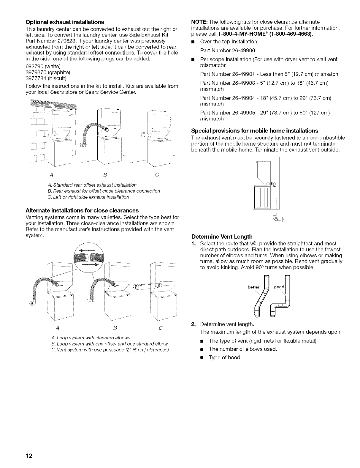
Optional exhaust installations
This laundry center can be converted to exhaust out the right or
left side. To convert the laundry center, use Side Exhaust Kit
Part Number 279823. If your laundry center was previously
exhausted from the right or left side, it can be converted to rear
exhaust by using standard offset connections. To cover the hole
in the side, one of the following plugs can be added:
692790 (white)
3979370 (graphite)
3977784 (biscuit)
Follow the instructions in the kit to install. Kits are available from
your local Sears store or Sears Service Center.
ili:iii:?i¸
NOTE: The following kits for close clearance alternate
installations are available for purchase. For further information,
please call 1-800-4-MY-HOME ®(1-800-469-4663).
• Over thetop Installation:
Part Number 26-49900
• Periscope Installation (For use with dryer vent to wall vent
mismatch):
Part Number 26-49901 - Less than 5" (12.7 cm) mismatch
Part Number 26-49908 - 5" (12.7 cm) to 18" (45.7 cm)
mismatch
Part Number 26-49904 - 18" (45.7 cm) to 29" (73.7 cm)
mismatch
Part Number 26-49905 - 29" (73.7 cm) to 50" (127 cm)
mismatch
I
_) r L_/;ii_
,F
C
A. Standard rear offset exhaust installation
B. Rear exhaust for offset close clearance connection
C. Left or right side exhaust installation
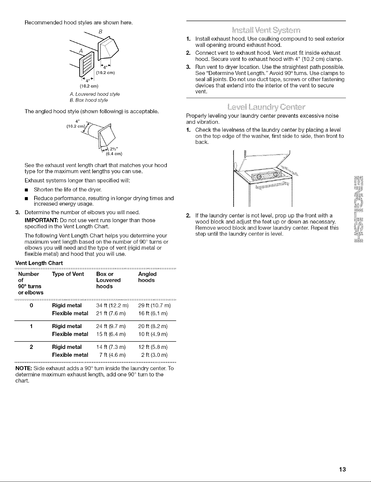
Alternate installations for close clearances
Venting systems come in many varieties. Select the type best for
your installation. Three close-clearance installations are shown.
Refer to the manufacturer's instructions provided with the vent
system.
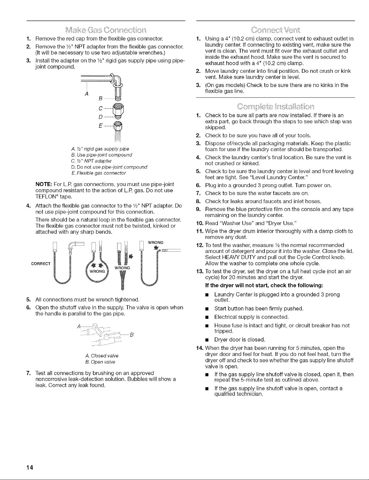
Special provisions for mobile home installations
The exhaust vent must be securely fastened to a noncombustible
portion of the mobile home structure and must not terminate
beneath the mobile home. Terminate the exhaust vent outside.
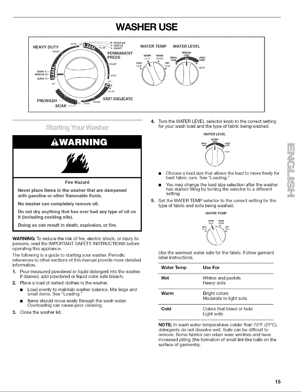
Determine Vent Length
1. Select the route that will provide the straightest and most
direct path outdoors. Plan the installation to use the fewest
number of elbows and turns. When using elbows or making
turns, allow as much room as possible. Bend vent gradually
to avoid kinking. Avoid 90° turns when possible.
12
A. Loop system with standard elbows
B. Loop system with one offset and one stardard elbow
C. Vent system with one periscope (2" [5 cm] clearance)
2. Determine vent length.
The maximum length of the exhaust system depends upon:
• The type of vent (rigid metal or flexible metal).
• The number of elbows used.
• Type of hood.
Recommended hood styles are shown here.
B
(10.2crn)
A.Louvered hood style
B.Box hood style
1. Install exhaust hood. Use caulking compound to seal exterior
wall opening around exhaust hood.
2. Connect vent to exhaust hood. Vent must fit inside exhaust
hood. Secure vent to exhaust hood with 4" (10.2 cm) clamp.
3. Run vent to dryer location. Use the straightest path possible.
See "Determine Vent Length." Avoid 90° turns. Use clamps to
seal all joints. Do not use duct tape, screws or other fastening
devices that extend into the interior of the vent to secure
vent.
The angled hood style (shown following) is acceptable.
See the exhaust vent length chart that matches your hood
type for the maximum vent lengths you can use.
Exhaust systems longer than specified will:
• Shorten the life of the dryer.
• Reduce performance, resulting in longer drying times and
increased energy usage.
3. Determine the number of elbows you will need.
IMPORTANT: Do not use vent runs longer than those
specified in the Vent Length Chart.
The following Vent Length Chart helps you determine your
maximum vent length based on the number of 90° turns or
elbows you will need and the type of vent (rigid metal or
flexible metal) and hood that you will use.
Vent Length Chart
Number Type of Vent Box or
of Louvered
90° turns hoods
or elbows
Angled
hoods
Properly leveling your laundry center prevents excessive noise
and vibration.
1. Check the levelness of the laundry center by placing a level
on the top edge of the washer, first side to side, then front to
back.
If the laundry center is not level, prop up the front with a
wood block and adjust the feet up or down as necessary.
Remove wood block and lower laundry center. Repeat this
step until the laundry center is level.
0 Rigid metal 34 ft (12.2 m) 29 ft (10.7 m)
Flexible metal 21 ft (7.6 m) 16 ft (6.1 m)
1 Rigid metal 24 ft (9.7 m) 20 ft (8.2 m)
Flexible metal 15 ft (6.4 m) 10 ft (4.9 m)
2 Rigid metal 14 ft (7.3 m) 12 ft (5.8 m)
Flexible metal 7 ft (4.6 m) 2 ft (3.0 m)
NOTE: Side exhaust adds a 90° turn inside the laundry center. To
determine maximum exhaust length, add one 90° turn to the
chart.
13
i_i,iii_i:;i_ili,_i:_:!_¸_iiiiiiili_i!!!i_!!:ii_iiiiiiiiii',',_ii::ii_i__ii__,_!i!_,_::ii',',illiiii,_ii:ii:_,__
f.
Remove the red cap from the flexible gas connector.
2.
Remove the 1/2"NPT adapter from the flexible gas connector.
(It will be necessary to use two adjustable wrenches.)
3,
Install the adapter on the 1/2"rigid gas supply pipe using pipe-
joint compound.
1. Using a 4" (10.2 cm) clamp, connect vent to exhaust outlet in
laundry center. If connecting to existing vent, make sure the
vent is clean. The vent must fit over the exhaust outlet and
inside the exhaust hood. Make sure the vent is secured to
exhaust hood with a 4" (10.2 cm) clamp.
2. Move laundry center into final position. Do not crush or kink
vent. Make sure laundry center is level.
3. (On gas models) Check to be sure there are no kinks in the
flexible gas line.
D
A. _2"rigid gas supply pipe
B.Usepipe-joint compound
C. _2"NPTadapter
D.Do not use pipe-joint compound
E.Flexiblegas connector
NOTE: For L.R gas connections, you must use pipe-joint
compound resistant to the action of LR gas. Do not use
TEFLON ®tape.
4,
Attach the flexible gas connector to the 1/2"NPT adapter. Do
not use pipe-joint compound for this connection.
There should be a natural loop in the flexible gas connector.
The flexible gas connector must not be twisted, kinked or
attached with any sharp bends.
CORRECT
WRONG - =
5. All connections must be wrench tightened.
6. Open the shutoff valve in the supply. The valve is open when
the handle is parallel to the gas pipe.
u
A.Closed valve
B.Open valve
7.
Test all connections by brushing on an approved
noncorrosive leak-detection solution. Bubbles will show a
leak. Correct any leak found.
Check to be sure all parts are now installed. If there is an
extra part, go back through the steps to see which step was
skipped.
2,
Check to be sure you have all of your tools.
3.
Dispose of/recycle all packaging materials. Keep the plastic
foam for use if the laundry center should be transported.
4.
Check the laundry center's final location. Be sure the vent is
not crushed or kinked.
5.
Check to be sure the laundry center is level and front leveling
feet are tight. See "Level Laundry Center."
6.
Plug into a grounded 3 prong outlet. Turn power on.
7.
Check to be sure the water faucets are on.
8.
Check for leaks around faucets and inlet hoses.
g.
Remove the blue protective film on the console and any tape
remaining on the laundry center.
10.
Read "Washer Use" and "Dryer Use."
11.
Wipe the dryer drum interior thoroughly with a damp cloth to
remove any dust.
12.
To test the washer, measure 1/2the normal recommended
amount of detergent and pour it into the washer. Close the lid.
Select HEAVY DUTY and pull out the Cycle Control knob.
Allow the washer to complete one whole cycle.
13.
To test the dryer, set the dryer on a full heat cycle (not an air
cycle) for 20 minutes and start the dryer.
If the dryer will not start, check the following:
• Laundry Center is plugged into a grounded 3 prong
outlet.
• Start button has been firmly pushed.
• Electrical supply is connected.
• House fuse is intact and tight, or circuit breaker has not
tripped.
• Dryer door is closed.
14.
When the dryer has been running for 5 minutes, open the
dryer door and feel for heat. If you do not feel heat, turn the
dryer off and check to see whether the gas supply line shutoff
valve is open.
• If the gas supply line shutoff valve is closed, open it, then
repeat the 5-minute test as outlined above.
• If the gas supply line shutoff valve is open, contact a
qualified technician.
14
HEAVYDUTY
RINSE
SOAK
...............................................................................10 REGULAR
SP//V
WASHER USE
GEI_T[E
SHORT
PERMANENT
PRESS
SPIN
KNIT/DEL|CATE
WATERTEMP WATER LEVEL
WARM WAI{M LOAD
COLD WARM LOAD LDAD
6fJL_ HOT O ®
e RESET
MEBUUM
SMALL lARGE
Turn the WATER LEVEL selector knob to the correct setting
for your wash load and the type of fabric being washed.
WATER LEVEL
MEdiUM
[O_D
SMALL LARGE
Fire Hazard
Never place items in the washer that are dampened
with gasoline or ether flammable fluids°
No washer can completely remove oH,
Do not dry anything that has ever had any type of oil on
it (including cooking oils).
Doing so can result in death, explosion, or fire,
WARNING: To reduce the risk of fire, electric shock, or injury to
persons, read the IMPORTANT SAFETY INSTRUCTIONS before
operating this appliance.
The following is a guide to starting your washer. Periodic
references to other sections of this manual provide more detailed
information.
1. Pour measured powdered or liquid detergent into the washer.
If desired, add powdered or liquid color safe bleach.
2. Place a load of sorted clothes in the washer.
• Load evenly to maintain washer balance. Mix large and
small items. See "Loading."
• Items should move easily through the wash water.
Overloading can cause poor cleaning,
3. Close the washer lid.
• Choose a load size that allows the load to move freely for
best fabric care. See "Loading."
• You may change the load size selection after the washer
has started filling by turning the selector to a different
setting.
Set the WATER TEMP selector to the correct setting for the
type of fabric and soils being washed.
WATER TEMP
C015 WARM
C0L_ ® ® aef
c0[b¢ C_!Lb
Use the warmest water safe for the fabric. Follow garment
label instructions.
Water Temp Use For
_W_
Hot Whites and pastels
Heavy soils
Warm Bright colors
Moderate to light soils
Cold Colors that bleed or fade
Light soils
NOTE: In wash water temperatures colder than 70°F (21°C),
detergents do not dissolve well. Soils can be difficult to
remove. Some fabrics can retain wear wrinkles and have
increased pilling (the formation of small lint-like balls on the
surface of garments).
15
6=
Push in the Cycle Control knob and turn it clockwise to the
wash cycle you want. Pull out the Cycle Control knob to start
the washer.
To stop or restart your washer:
• To stop the washer at any time, push in the Cycle Control
knob.
• To restart the washer, close the lid (if open) and pull out
the Cycle Control knob.
This section describes the available wash cycles and will help
you make the best cycle selections for your wash loads. Each
cycle is designed for different types of fabric and soil levels.
• The washer pauses briefly throughout each cycle. These
pauses are normal. Refer to "Normal Sounds" for sounds you
may hear during a wash cycle.
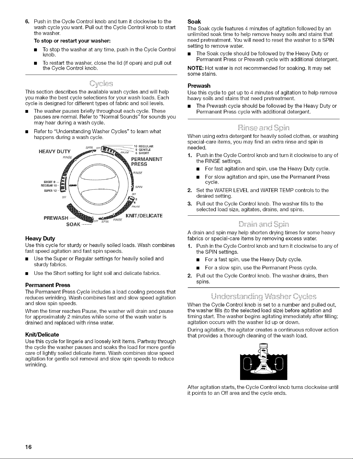
• Refer to "Understanding Washer Cycles" to learn what
happens during a wash cycle.
RINSE
OFF
KN|T/DEL|CATE
SOAK .............................
_INSE
Heavy Duty
Use this cycle for sturdy or heavily soiled loads. Wash combines
fast speed agitation and fast spin speeds.
• Use the Super or Regular settings for heavily soiled and
sturdy fabrics.
• Use the Short setting for light soil and delicate fabrics.
Permanent Press
The Permanent Press Cycle includes a load cooling process that
reduces wrinkling. Wash combines fast and slow speed agitation
and slow spin speeds.
When the timer reaches Pause, the washer will drain and pause
for approximately 2 minutes while some of the wash water is
drained and replaced with rinse water.
Knit/Delicate
Use this cycle for lingerie and loosely knit items. Partway through
the cycle the washer pauses and soaks the load for more gentle
care of lightly soiled delicate items. Wash combines slow speed
agitation for gentle soil removal and slow spin speeds to reduce
wrinkling.
Soak
The Soak cycle features 4 minutes of agitation followed by an
unlimited soak time to help remove heavy soils and stains that
need pretreatment. You will need to reset the washer to a SPIN
setting to remove water.
• The Soak cycle should be followed by the Heaw Duty or
Permanent Press or Prewash cycle with additional detergent.
NOTE: Hot water is not recommended for soaking. It may set
some stains.
Prewash
Use this cycle to get up to 4 minutes of agitation to help remove
heavy soils and stains that need pretreatment.
• The Prewash cycle should be followed by the Heavy Duty or
Permanent Press cycle with additional detergent.
When using extra detergent for heavily soiled clothes, or washing
special-care items, you may find an extra rinse and spin is
needed.
1. Push inthe Cycle Control knob and turn it clockwise to any of
the RINSE settings.
• For fast agitation and spin, use the Heavy Duty cycle.
• For slow agitation and spin, use the Permanent Press
cycle.
2. Set the WATER LEVEL and WATER TEMP controls to the
desired setting.
3. Pull out the Cycle Control knob. The washer fills to the
selected load size, agitates, drains, and spins.
A drain and spin may help shorten drying times for some heavy
fabrics or special-care items by removing excess water.
1. Push inthe Cycle Control knob and turn it clockwise to any of
the SPIN settings.
• For a fast spin, use the Heavy Duty cycle.
• For a slow spin, use the Permanent Press cycle.
2. Pull out the Cycle Control knob. The washer drains, then
spins.
When the Cycle Control knob is set to a number and pulled out,
the washer fills (to the selected load size) before agitation and
timing start. The washer begins agitating immediately after filling;
agitation occurs with the washer lid up or down.
During agitation, the agitator creates a continuous rollover action
that provides a thorough cleaning of the wash load.
16
After agitation starts, the Cycle Control knob turns clockwise until
it points to an Off area and the cycle ends.
 Loading...