

Page 1
®
SENSOR SMART TMGas Dryer
KING SIZE TMCapacity Plus
Secadora a Gas SENSOR SMART TM
de capacidad extra grande
(KING SIZE TM"Plus")
ii'V'!,:,:i:ili!!!_i_i_j_iLjiii_i!:!i,_iiiii,C!i_!!i!i_¸LjiiiS,C_,_,¸_ii!!j¸C:,ii_iiiiCii_i!ii:i!i_ii_C!ii_:iiiiil;_¸
Models/Modelos 110.7408_, 7206_, 7208_
= color number/nemero de color
iiiiii!Jiiiiiiiiiii!il
8533586 Sears Roebuck and Co., Hoffman Estates, IL 60179 U.S.A. www.sears.com
Page 2
TABLE OF CONTENTS
PROTECTION AGREEMENTS ....................................................... 2
WARRANTY ..................................................................................... 2
DRYER SAFETY .............................................................................. 3
INSTALLATION INSTRUCTIONS .................................................. 5
Tools and Parts ............................................................................ 5
Location Requirements ............................................................... 5
Electrical Requirements ................................................................ 6
Gas Supply Requirements ........................................................... 7
Venting Requirements .................................................................. 8
Plan Vent System ......................................................................... 8
Install Vent System .................................................................... 10
Install Leveling Legs .................................................................. 10
Level Dryer ................................................................................. 11
Make Gas Connection ............................................................... 11
Connect Vent ............................................................................. 11
Complete Installation ................................................................. 11
DRYER USE ................................................................................. 12
Starting Your Dryer .................................................................... 12
Stopping Your Dryer .................................................................. 12
Pausing or Restarting ................................................................ 13
Loading ...................................................................................... 13
Drying and Cycle Tips ............................................................... 13
Dryer Status ............................................................................... 14
Cycles ........................................................................................ 14
Options ...................................................................................... 15
Modifiers .................................................................................... 15
Changing Cycles, Options
and Modifiers ............................................................................. 16
TUMBLE FREF MHeated Dryer Rack ....................................... 16
DRYER CARE ............................................................................... 16
Cleaning the Dryer Location ...................................................... 16
Cleaning the Lint Screen ........................................................... 17
Cleaning the Dryer Interior ........................................................ 17
Removing Accumulated Lint ..................................................... 17
Vacation and Moving Care ........................................................ 17
Changing the Drum Light .......................................................... 17
TROUBLESHOOTING .................................................................. 18
SERVICE NUMBERS ............................................... BACK COVER
PROTECTION AGREEMENTS
Master Protection Agreements
Congratulations on making a smart purchase. Your new
Kenmore ®product is designed and manufactured for years of
dependable operation. But like all products, it may require
preventive maintenance or repair from time to time. That's when
having a Master Protection Agreement can save you money and
aggravation.
Purchase a Master Protection Agreement now and protect
yourself from unexpected hassle and expense.
The Master Protection Agreement also helps extend the life of
your new product. Here's what's included in the Agreement:
v' Expert service by our 12,000 professional repair specialists
v' Unlimited service and no charge for parts and labor on all
covered repairs
v' "No-lemon" guarantee - replacement of your covered
product if four or more product failures occur within twelve
months
v' Product replacement if your covered product can't be fixed
v' Annual Preventive Maintenance Check at your request - no
extra charge
v' Fast help by phone - phone support from a Sears technician
on products requiring in-home repair, plus convenient repair
scheduling
v' Power surge protection against electrical damage due to
power fluctuations
v' Rental reimbursement if repair of your covered product takes
longer than promised
Once you purchase the Agreement, a simple phone call is all that
it takes for you to schedule service. You can call anytime day or
night, or schedule a service appointment online.
Sears has over 12,000 professional repair specialists, who have
access to over 4.5 million quality parts and accessories. That's
the kind of professionalism you can count on to help prolong the
life of your new purchase for years to come. Purchase your
Master Protection Agreement today!
Some limitations and exclusions apply. For prices and
additional information, call 1-800-827-6655.
Sears Installation Service
For Sears professional installation of home appliances, garage
door openers, water heaters, and other major home items, in the
U.S.A. call 1-800-4-MY-HOME ®.
WARRANTY
Full One-Year Warranty on Mechanical and Electrical Parts
For one year from the date of purchase, when this dryer is
installed and operated according to the instructions provided in
this Use and Care Guide, Sears will repair this dryer, free of
charge, if defective in materials or workmanship.
NOTE: Exhausting this dryer with a plastic vent can void this
warranty. See "Installation Instructions" for the complete exhaust
requirements for this dryer.
Limited Two-Year Warranty on SENSOR SMART TM
Electronic Control Board
For the second year from the date of purchase, Sears will replace
the electronic control board if defective in material or
workmanship. You will be charged for labor after the first year.
Warranty Restriction
If the dryer is subject to other than private family use, the above
warranty coverage is effective for only 90 days.
Page 3
Warranty Service
Warranty service is available by contacting the nearest Sears
Service Center. This warranty applies only while the product is in
use in the United States.
This warranty gives you specific legal rights and you may also
have other rights which vary from state to state.
For Sears Warranty information or to contact a Sears Service
Center, please refer to the service numbers located on the back
page of this manual.
Sears, Roebuck and Co.
D/817WA, Hoffman Estates, IL 60179
Product Record
In the space following, record your complete model number,
serial number, and purchase date. You can find this information
on the model and serial number label, located at the top inside
dryer door well.
Have this information available to help you quickly obtain
assistance or service when you contact Sears concerning your
appliance.
Model number 110.
Serial number
Purchase date
Save these instructions and your sales receipt for future
reference.
DRYER SAFETY
Your safety and the safety of others are very important.
We have provided many important safety messages in this manual and on your appliance. Always read and obey all safety
messages.
This is the safety alert symbol.
This symbol alerts you to potential hazards that can kill or hurt you and others.
All safety messages will follow the safety alert symbol and either the word "DANGER" or "WARNING."
These words mean:
You can be killed or seriously injured if you don't immediately
follow instructions.
You can be killed or seriously injured if you don't follow
instructions.
All safety messages will tell you what the potential hazard is, tell you how to reduce the chance of injury, and tell you what can
happen if the instructions are not followed.
I WARNING: For your safety, the information in this manual must be followed to minimize
the risk of fire or explosion, or to prevent property damage, personal injury, or death.
- Do not store or use gasoline or other flammable vapors and liquids in the vicinity of this
or any other appliance.
- WHAT TO DO IF YOU SMELL GAS:
• Do not try to light any appliance.
• Do not touch any electrical switch; do not use any phone in your building.
• Clear the room, building, or area of all occupants.
• Immediately call your gas supplier from a neighbor's phone. Follow the gas supplier's
instructions.
• If you cannot reach your gas supplier, call the fire department.
- Installation and service must be performed by a qualified installer, service agency, or
the gas supplier.
Page 4
In the State of Massachusetts, the following installation instructions apply:
_, Installations and repairs must be performed by a qualified or licensed contractor, plumber, or gasfitter qualified or licensed by
the State of Massachusetts.
_, If using a ball valve, it shall be a T-handle type.
_, A flexible gas connector, when used, must not exceed 3 feet.
iMPORTANT SAFETY iNSTRUCTiONS
WARNUNG: To reduce the risk of fire, electric shock, or injury to persons when using the dryer, follow basic precautions,
including the following:
m Read all instructions before using the dryer.
m Do not place items exposed to cooking oils in your dryer.
Htems contaminated with cooking oils may contribute to
a chemical reaction that could cause a Ioad to catch fire.
m Do not dry articles that have been previously cleaned in,
washed in, soaked in, or spotted with gasoline, dry-
cleaning solvents, other flammable, or explosive
substances as they give off vapors that could ignite or
explode.
m Do not allow children to play on or in the dryer. Close
supervision of children is necessary when the dryer is
used near children.
m Before the dryer is removed from service or discarded,
remove the door to the drying compartment.
m Do not reach into the dryer if the drum is moving.
m Do not install or store the dryer where it will be exposed
to the weather.
m Do not tamper with controls.
m Do not repair or replace any part of the dryer or attempt
any servicing unless specifically recommended in this
Use and Care Guide or in published user-repair
instructions that you understand and have the skills to
carry out.
m Do not use fabric softeners or products to eliminate static
unless recommended by the manufacturer of the fabric
softener or product.
m Do not use heat to dry articles containing foam rubber or
similarly textured rubber-like materials.
m Clean Iint screen before or after each load.
m Keep area around the exhaust opening and adjacent
surrounding areas free from the accumulation of lint, dust,
and dirt.
_, The interior of the dryer and exhaust vent should be
cleaned periodically by qualified service personnel.
_, See insta!lation instructions for grounding requirements.
SAVE THESE iNSTRUCTiONS
IMPORTANT: The gas instailation must conform with local codes, or in the absence of local codes, with the Nationai Fuel Gas
Code, ANSH Z223,1/NFPA 54_
The dryer must be electrically grounded in accordance with local codes, or in the absence of local codes, with the Nationai
Electrical Code, ANSH/NFPA 70_
Page 5
INSTALLATION INSTRUCTIONS
Check that you have everything necessary for correct installation.
Proper installation is your responsibility.
8" or 10" pipe wrench
8" or 10" adjustable
wrench (for gas
connections)
Flat-blade screwdriver
Adjustable wrench that
opens to 1" (2.5 cm) or
hex-head socket wrench
(for adjusting dryer feet)
Level
• 1A" nut driver or socket
wrench
• Knife
• Vent clamps
• Pipe-joint compound
resistant to L.R gas
• Caulking gun and
compound (for installing
new exhaust vent)
• Pliers
Parts supplied:
Remove parts package from dryer drum. Check that all parts
were included.
4 leveling legs
Parts needed:
Check local codes and with gas supplier, check existing gas
supply, electrical supply and venting, and read "Electrical
Requirements," "Gas Supply Requirements" and "Venting
Requirements" before purchasing parts.
Mobile home installations require special parts (listed following)
available for purchase from your local Sears store or Sears
Service Center. For further information, please call
1-800-4-MY-HOME ®(1-800-469-4663}.
• Mobile Home Installation Kit. Ask for Part Number 346764.
• Metal exhaust system hardware.
Expmosion Hazard
Keep flammable materials and vapors, such as
gasomine, away from dryer.
Pmacedryer at Beast 18 inches (48 cm) above the floor
for a garage installation.
Failure to do so can resumt in death, expmosion, or fire.
You will need
• A location that allows for proper exhaust installation. A gas
dryer must be exhausted to the outdoors. See "Venting
Requirements."
• A grounded electrical outlet located within 2 ft (61 cm) of
either side of the dryer. See "Electrical Requirements."
• A sturdy floor to support the dryer with a total weight (dryer
and load) of 200 Ibs (90.7 kg).
A level floor with a maximum slope of 1" (2.5 cm) under entire
dryer. (If slope is greater than 1" [2.5 cm], install Extended
Dryer Feet Kit, Part Number 279810.) Clothes may not tumble
properly and dryers with automatic sensor cycles may not
operate correctly if dryer is not level.
Do not operate your dryer at temperatures below 45°F (7°C). At
lower temperatures, the dryer might not shut off at the end of an
automatic cycle. Drying times can be extended.
The dryer must not be installed or stored in an area where it will
be exposed to water and/or weather.
Check code requirements. Some codes limit, or do not permit,
installation of the dryer in garages, closets, mobile homes, or
sleeping quarters. Contact your local building inspector.
NOTE: No other fuel-burning appliance can be installed in the
same closet as a dryer.
Page 6
Installation Clearances
The location must be large enough to allow the dryer door to
open fully.
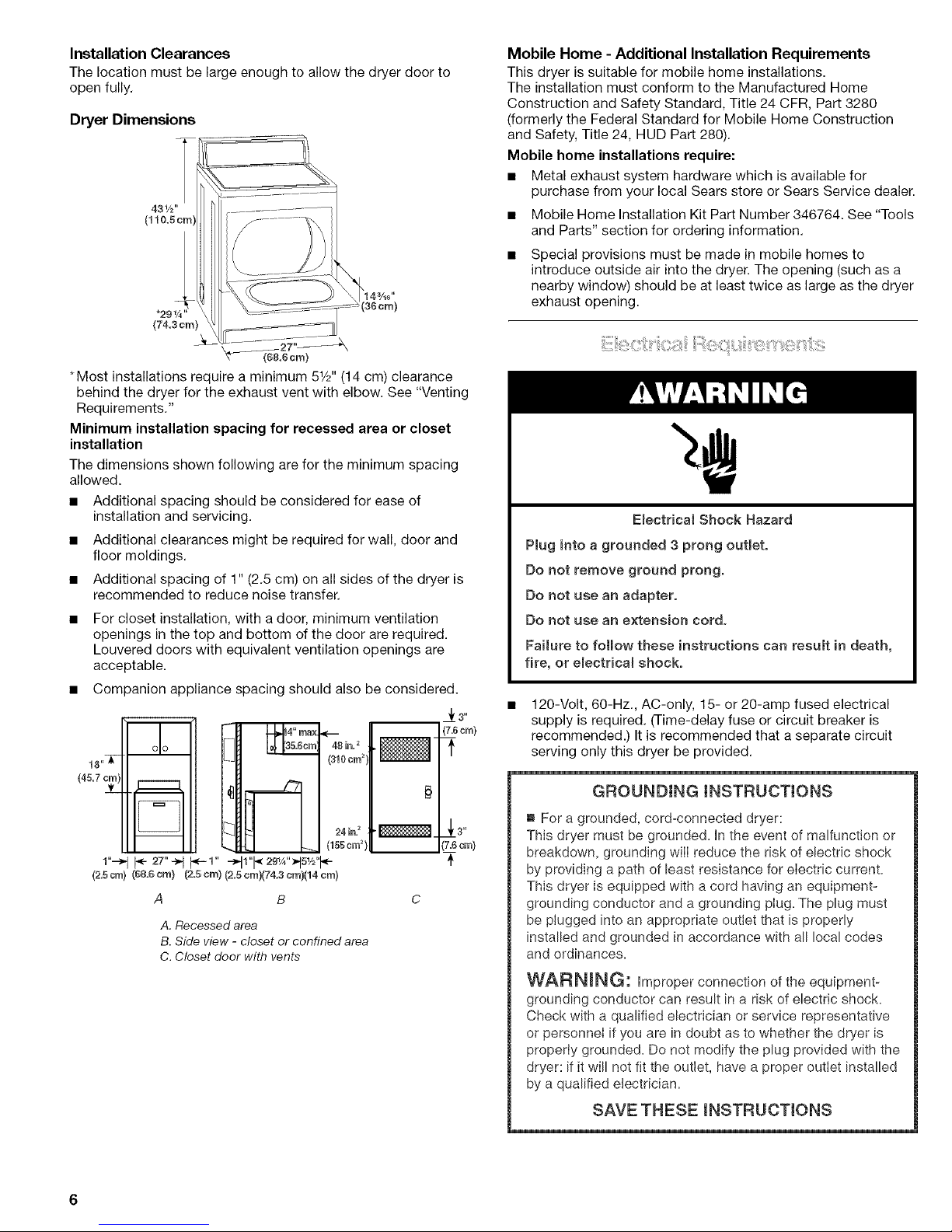
Dryer Dimensions
(6&6cm}
*Most installations require a minimum 51/2'' (14 cm) clearance
behind the dryer for the exhaust vent with elbow. See "Venting
Requirements."
Minimum installation spacing for recessed area or closet
installation
The dimensions shown following are for the minimum spacing
allowed.
• Additional spacing should be considered for ease of
installation and servicing.
• Additional clearances might be required for wall, door and
floor moldings.
• Additional spacing of 1" (2.5 cm) on all sides of the dryer is
recommended to reduce noise transfer.
For closet installation, with a door, minimum ventilation
openings in the top and bottom of the door are required.
Louvered doors with equivalent ventilation openings are
acceptable.
• Companion appliance spacing should also be considered.
n
olo
A B
Jr s"
17.5crn)
3"
'7=5crn}
A, Recessed area
B. Side view - closet or confined area
C. Closet door with vents
Mobile Home - Additional Installation Requirements
This dryer is suitable for mobile home installations.
The installation must conform to the Manufactured Home
Construction and Safety Standard, Title 24 CFR, Part 3280
(formerly the Federal Standard for Mobile Home Construction
and Safety, Title 24, HUD Part 280).
Mobile home installations require:
• Metal exhaust system hardware which is available for
purchase from your local Sears store or Sears Service dealer.
• Mobile Home Installation Kit Part Number 346764. See "Tools
and Parts" section for ordering information.
Special provisions must be made in mobile homes to
introduce outside air into the dryer. The opening (such as a
nearby window) should be at least twice as large as the dryer
exhaust opening.
Emectricai Shock Hazard
Plug into a grounded 3 prong outlet.
Do not remove ground prong.
Do not use an adapter.
Do not use an extension cord.
Faimureto follow these instructions can result in death,
fire, or emectrical shock.
120-Volt, 60-Hz., AC-only, 15- or 20-amp fused electrical
supply is required. (Time-delay fuse or circuit breaker is
recommended.) It is recommended that a separate circuit
serving only this dryer be provided.
GROUNDING mNSTRUCTIONS
" For a grounded, cord-connected dryer:
This dryer must be grounded. In the event of malfunction or
breakdown, grounding wilI reduce the risk of electric shock
by providing a path of least resistance for electric current.
This dryer is equipped with a cord having an equipment-
grounding conductor and a grounding plug. The plug must
be plugged into an appropriate outlet that is properly
installed and grounded in accordance with all local codes
and ordinances=
WARNING: Improper connection of the equipment-
grounding conductor can result in a risk of electric shock.
Check with a qualified electrician or service representative
or personnel ifyou are in doubt as to whether the dryer is
properly grounded. Do not modify the plug provided with the
dryer: if it will not fit the outlet, have a proper outlet installed
by a qualified electrician=
SAVE THESE INSTRUOTmONS
Page 7

Explosion Hazard
Use a new AGA or CSA approved gas supply mine.
tnstaim a shut-off vaive.
Securely tighten ail gas connections.
if connected to LP, have a qualified person make sure
gas pressure does not exceed 13" (33 cm) water
comumn.
Exampmes of a quamified person include:
licensed heating personnel,
authorized gas company personnem, and
authorized service personnel
Failure to do so can result in death, expmosion, or fire.
Gas Type
Natural Gas:
This dryer is equipped for use with natural gas. It is design-
certified by CSA International for L.R (propane or butane) gases
with appropriate conversion.
• Your dryer must have the correct burner for the type of gas in
your home. Burner information is located on the rating plate
in the door well of your dryer. Ifthis information does not
agree with the type of gas available, contact your local Sears
store or Sears Service Center.
L.P. gas conversion:
Conversion must be made by a qualified technician.
No attempt shall be made to convert the appliance from the gas
specified on the model/serial rating plate for use with a different
gas without consulting the serving gas supplier.
Gas Supply Line:
• 1/2"IPSpipe isrecommended.
• %" approved tubing is acceptable for lengths under 20 ft
(6.1 m) if local codes and gas supplier permit.
• Must include Vs"NPT minimum plugged tapping accessible
for test gauge connection, immediately upstream of the gas
connection to the dryer (see illustration).
• Must include a shutoff valve:
An individual shutoff valve must be installed within six (6) feet
(1.8 m) of the dryer in accordance with the National Fuel Gas
Code, ANSI Z223.1. The location should be easy to reach for
opening and closing.
A C E
B D
A. _" flexible gas connector
B. _" pipe to flare adapterfitting
C. _" NPT plugged tapping
D. Y2"NPT gas supply line
E.Gas shutoff valve
Gas supply connection requirements
There are many methods by which your gas dryer can be
connected to the gas supply. Listed here are some guidelines for
two different methods of connection.
Option 1 (Recommended Method):
Flexible stainless steel gas connector:
• If local codes permit, use a new flexible stainless steel gas
connector (Design Certified by the American Gas Association
or CSA International) to connect your dryer to the rigid gas
supply line. Use an elbow and a 3/8"flare x 3/8"NPT adapter
fitting between the stainless steel gas connector and the
dryer gas pipe, as needed to prevent kinking.
Option 2 (Alternate Method):
Approved aluminum or copper tubing:
• Lengths under 20 ft (6.1 m) can use 3/8"approved tubing (if
codes and gas supplier permit).
• If you are using natural gas, do not use copper tubing.
• %" flare x %" NPT adapter fitting between dryer pipe and %"
approved tubing
• Lengths over 20 ft (6.1 m) should use larger tubing and a
different size adapter fitting.
• If your dryer has been converted to use L.R gas, %" L.R
compatible copper tubing can be used. If the total length of
the supply line is more than 20 ft (6.1 m), use larger pipe.
NOTE: Pipe joint compounds that resist the action of L.R gas
must be used. Do not use TEFLON _ttape.
Dryer Gas Pipe
• The gas pipe that comes out through the rear of your dryer
has a %" male pipe thread.
A ¸¸¸
A. _/*" NPT gas supply line
B. _" NPT dryer pipe
1-®TEFLON is a registered trademark of E.I. Du Pont De Nemours and Company.
Page 8
Burner Input Requirements:
Elevations up to 10,000 ft (3,048 meters):
• The design of this dryer is certified by CSA International for
use at altitudes up to 10,000 ft (3,048 m) above sea level at
the B.T.U. rating indicated on the model/serial number plate.
Burner input adjustments are not required when the dryer is
operated up to this elevation.
Elevations above 10,000 ft (3,048 meters):
• When installed above 10,000 ft (3,048 m) a 4% reduction of
the burner B.T.U. rating shown on the model/serial number
plate is required for each 1,000 ft (305 m) increase in
elevation.
Gas Supply Pressure Testing
• The dryer must be disconnected from the gas supply piping
system during pressure testing at pressures greater than
1/2psi.
Fire Hazard
Use a heavy metal vent.
Do not use a pmastic vent.
Do not use a metal foil vent.
Faimureto follow these instructions can result in death
or fire.
WARNING: To reduce the risk of fire, this dryer MUST BE
EXHAUSTED OUTDOORS.
4" (10.2 cm) heavy metal exhaust vent and clamps must be used.
DURASAFE TM venting products are recommended and are
available from your local Sears store or Sears Service Center.
DURASAFE TM vent products can be purchased from your dealer.
For further information, please call 1-800-4-MY-HOME ®
(1-800-469-4663) or visit our Internet site at: www.sears.com
The dryer exhaust must not be connected into any gas vent,
chimney, wall, ceiling, or a concealed space of a building.
Do not use an exhaust hood with a magnetic latch.
Do not install flexible metal vent in enclosed walls, ceilings or
floors.
Use clamps to seal all joints. Exhaust vent must not be
connected or secured with screws or other fastening devices
which extend into the interior of the duct. Do not use duct
tape.
IMPORTANT: Observe all governing codes and ordinances.
improper venting can cause moisture and ()ntto collect
indoors, which may resumt in:
[] Moisture damage to woodwork, furniture, paint,
waiIpaper, carpets, etc=
[] Housecleaning problems and health problems.
Use a heavy metal vent. Do not use plastic or metal foil vent.
Rigid metal vent is recommended to prevent crushing and
kinking.
Flexible metal vent must be fully extended and supported when
the dryer is in its final position. Remove excess flexible metal vent
to avoid sagging and kinking that may result in reduced airflow
and poor performance.
An exhaust hood should cap the vent to prevent rodents and
insects from entering the home.
Exhaust hood must be at least 12" (30.5 cm) from the ground or
any object that may be in the path of the exhaust (such as
flowers, rocks or bushes, etc.).
If using an existing vent system, clean lint from the entire length
of the system and make sure exhaust hood is not plugged with
lint. Replace any plastic or metal foil vent with rigid metal or
flexible metal vent.
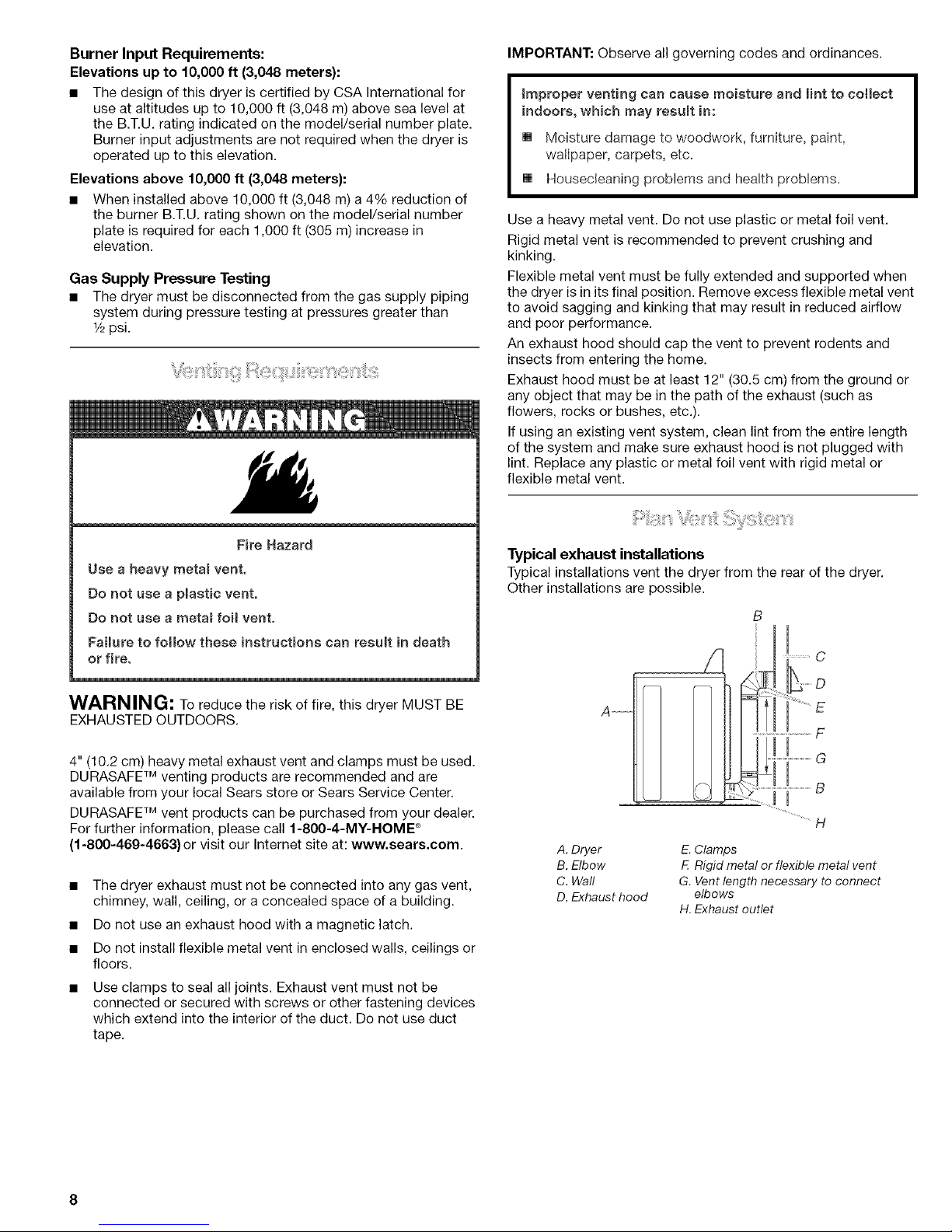
Typical exhaust installations
Typical installations vent the dryer from the rear of the dryer.
Other installations are possible.
A
/
B
................................H
A. Dryer
B. Elbow
C. Wall
D. Exhaust hood
E. Clamps
F. Rigid metal or flexible metal vent
G. Vent length necessary to connect
elbows
H. Exhaust outlet
Page 9
Optional exhaust installations
This dryer can be converted to exhaust out the right side, left
side, or through the bottom. Contact your local dealer to have the
dryer converted.
Fire Hazard
Cover unused exhaust holes with one of the folowing
kits:
279818 (white)
279819 (almond)
279915 (graphite)
279925 (biscuit)
Contact your local dealer°
Failure to fomlow these instructions can result in death,
fire, electrical shock, or serious injury.
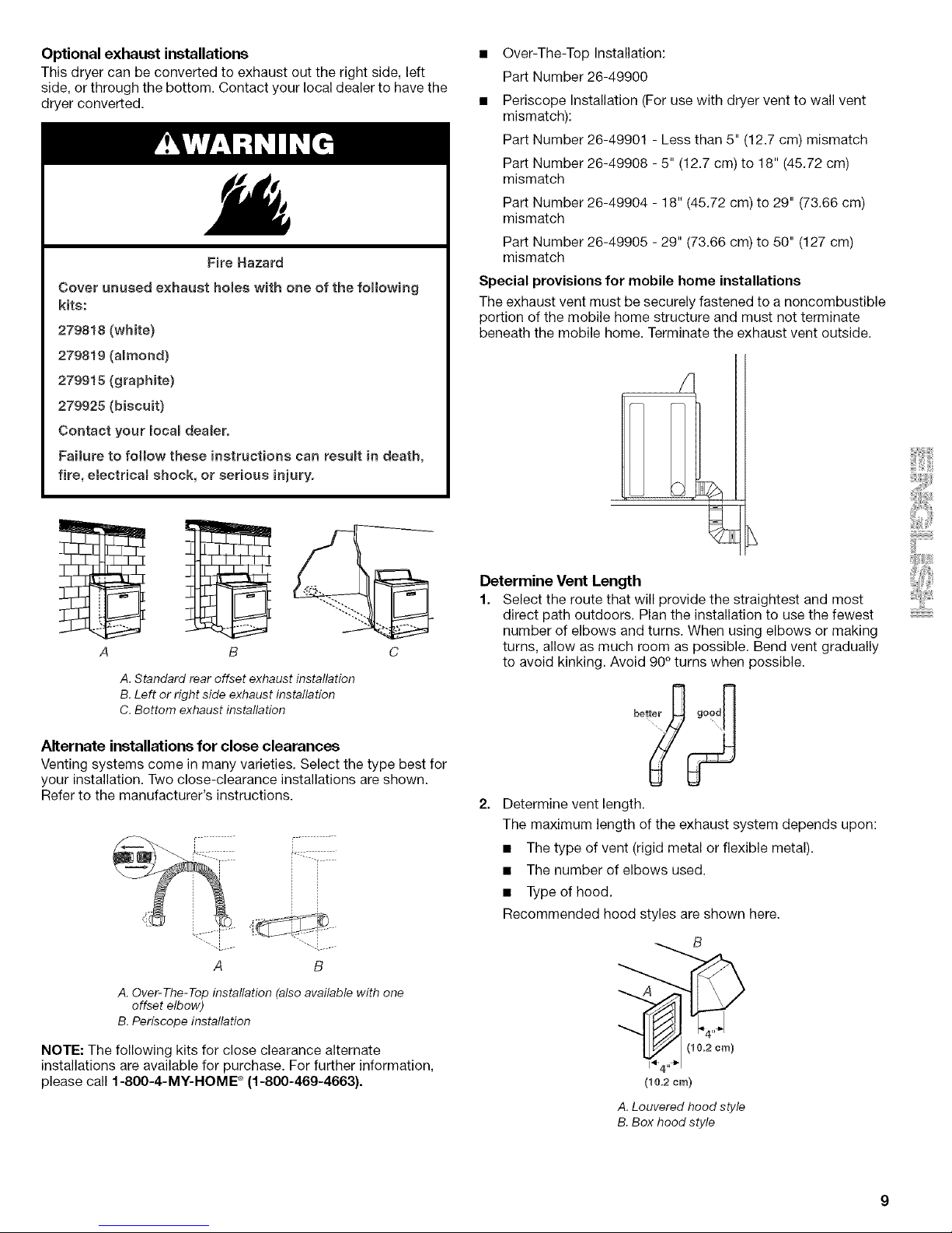
A
T!
B C
A. Standard rear offset exhaust installation
B. Left or right side exhaust installation
C. Bottom exhaust installation
Alternate installations for close clearances
Venting systems come in many varieties, Select the type best for
your installation. Two close-clearance installations are shown.
Refer to the manufacturer's instructions.
A B
A. Over-The-Top installation (also available with one
offset elbow)
B. Periscope installation
NOTE: The following kits for close clearance alternate
installations are available for purchase. For further information,
please call 1-800-4-MY-HOME ®(1-800-469-4663).
• Over-The-Top Installation:
Part Number 26-49900
• Periscope Installation (For use with dryer vent to wall vent
mismatch):
Part Number 26-49901 - Less than 5" (12.7 cm) mismatch
Part Number 26-49908 - 5" (12.7 cm) to 18" (45.72 cm)
mismatch
Part Number 26-49904 - 18" (45.72 cm) to 29" (73.66 cm)
mismatch
Part Number 26-49905 - 29" (73.66 cm) to 50" (127 cm)
mismatch
Special provisions for mobile home installations
The exhaust vent must be securely fastened to a noncombustible
portion of the mobile home structure and must not terminate
beneath the mobile home. Terminate the exhaust vent outside.
/
Determine Vent Length
1. Select the route that will provide the straightest and most
direct path outdoors. Plan the installation to use the fewest
number of elbows and turns. When using elbows or making
turns, allow as much room as possible. Bend vent gradually
to avoid kinking. Avoid 90° turns when possible.
Determine vent length.
The maximum length of the exhaust system depends upon:
• The type of vent (rigid metal or flexible metal).
• The number of elbows used.
• Type of hood.
Recommended hood styles are shown here.
B
(10.2 cm)
A. Louvered hood style
B. Box hood style
Page 10
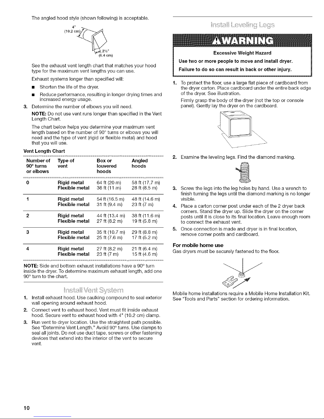
The angled hood style (shown following) is acceptable.
(8.4cm)
See the exhaust vent length chart that matches your hood
type for the maximum vent lengths you can use.
Exhaust systems longer than specified will:
3,
• Shorten the life of the dryer.
• Reduce performance, resulting in longer drying times and
increased energy usage.
Determine the number of elbows you will need.
NOTE: Do not use vent runs longer than specified in the Vent
Length Chart.
The chart below helps you determine your maximum vent
length based on the number of 90° turns or elbows you will
need and the type of vent (rigid or flexible metal) and hood
that you will use.
Vent Length Chart
Number of Type of Box or Angled
90° turns vent Iouvered hoods
or elbows hoods
0 Rigid metal 64 ft (20 m) 58 ft (17.7 m)
Flexible metal 36 ft (11 m) 28 ft (8.5 m)
1 Rigid metal 54 ft (16.5 m) 48 ft (14.6 m)
Flexible metal 31 ft (9.4 m) 23 ft (7 m)
2 Rigid metal 44 ft (13.4 m) 38 ft (11.6 m)
Flexible metal 27 ft (8.2 m) 19 ft (5.8 m)
3 Rigid metal 35 ft (10.7 m) 29 ft (8.8 m)
Flexible metal 25 ft (7.6 m) 17 ft (5.2 m)
4 Rigid metal 27 ft (8.2 m) 21 ft (6.4 m)
Flexible metal 23 ft (7 m) 15 ft (4.6 m)
NOTE: Side and bottom exhaust installations have a 90° turn
inside the dryer. To determine maximum exhaust length, add one
90° turn to the chart.
1,
2.
3.
ii ! :::iii:,ii;1::);i!i: i] 1;;ii:1i
Install exhaust hood. Use caulking compound to seal exterior
wall opening around exhaust hood.
Connect vent to exhaust hood. Vent must fit inside exhaust
hood. Secure vent to exhaust hood with 4" (10.2 cm) clamp.
Run vent to dryer location. Use the straightest path possible.
See "Determine Vent Length." Avoid 90° turns. Use clamps to
seal all joints. Do not use duct tape, screws or other fastening
devices that extend into the interior of the vent to secure
vent.
il_'_:!i:;;ii!:;;ili;i!_ilii
Excessive Weight Hazard
Use two or more people to move and install dryer.
Failure to do so can result in back or other injury.
1. To protect the floor, use a large flat piece of cardboard from
the dryer carton. Place cardboard under the entire back edge
of the dryer. See illustration.
Firmly grasp the body of the dryer (not the top or console
panel). Gently lay the dryer on the cardboard.
2,
Examine the leveling legs. Find the diamond marking.
3. Screw the legs into the leg holes by hand. Use a wrench to
finish turning the legs until the diamond marking is no longer
visible.
4. Place a carton corner post under each of the 2 dryer back
corners. Stand the dryer up. Slide the dryer on the corner
posts until it is close to its final location. Leave enough room
to connect the exhaust vent.
5. Once connection is made and dryer is in final location,
remove corner posts and cardboard.
For mobile home use
Gas dryers must be securely fastened to the floor.
Mobile home installations require a Mobile Home Installation Kit
See "Tools and Parts" section for ordering information.
10
Page 11
Check the levelness of the dryer. Check levelness first
side to side, then front to back.
If the dryer is not level, prop up the dryer using a wood block.
Use a wrench to adjust the legs up or down and check again for
levelness.
NOTE: It might be necessary to level the dryer again after it is
moved into its final position.
1,
2.
Remove the red cap from the gas pipe. Move the dryer close
to its final position.
Using a wrench to tighten, connect the gas supply to the
dryer. Use pipe joint compound on all non-flared male
threads. If flexible metal tubing is used, be sure there are
no kinks.
NOTE: For L.R gas connections, you must use pipe joint
compound resistant to the action of L.R gas. Do not use
TEFLON _ttape.
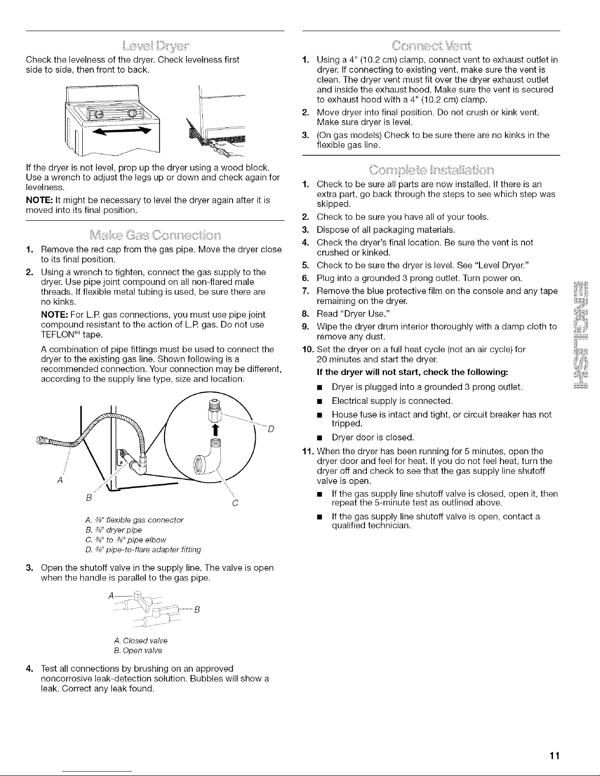
A combination of pipe fittings must be used to connect the
dryer to the existing gas line. Shown following is a
recommended connection. Your connection may be different,
according to the supply line type, size and location.
J
f
A
\
C
A. _" flexible gas connector
B. ¾" dryerpipe
C. _" to _" pipe elbow
D. _" pipe-to-flare adapter fitting
Open the shutoff valve in the supply line. The valve is open
when the handle is parallel to the gas pipe.
1. Using a4" (10.2 cm) clamp, connect vent to exhaust outlet in
dryer. If connecting to existing vent, make sure the vent is
clean. The dryer vent must fit over the dryer exhaust outlet
and inside the exhaust hood. Make sure the vent is secured
to exhaust hood with a 4" (10.2 cm) clamp.
2. Move dryer into final position. Do not crush or kink vent.
Make sure dryer is level.
3. (On gas models) Check to be sure there are no kinks in the
flexible gas line.
1. Check to be sure all parts are now installed. If there is an
extra part, go back through the steps to see which step was
skipped.
2. Check to be sure you have all of your tools.
3. Dispose of all packaging materials.
4. Check the dryer's final location. Be sure the vent is not
crushed or kinked.
5. Check to be sure the dryer is level. See "Level Dryer."
6. Plug into a grounded 3 prong outlet. Turn power on.
7. Remove the blue protective film on the console and any tape
remaining on the dryer.
8. Read "Dryer Use."
9. Wipe the dryer drum interior thoroughly with a damp cloth to
remove any dust.
10. Set the dryer on a full heat cycle (not an air cycle) for
20 minutes and start the dryer.
If the dryer will not start, check the following:
• Dryer is plugged into a grounded 3 prong outlet.
• Electrical supply is connected.
• House fuse is intact and tight, or circuit breaker has not
tripped.
• Dryer door is closed.
11. When the dryer has been running for 5 minutes, open the
dryer door and feel for heat. If you do not feel heat, turn the
dryer off and check to see that the gas supply line shutoff
valve is open.
• If the gas supply line shutoff valve is closed, open it, then
repeat the 5-minute test as outlined above.
• If the gas supply line shutoff valve is open, contact a
qualified technician.
A.Closed valve
B.Open valve
Test all connections by brushing on an approved
noncorrosive leak-detection solution. Bubbles will show a
leak. Correct any leak found.
11
Page 12
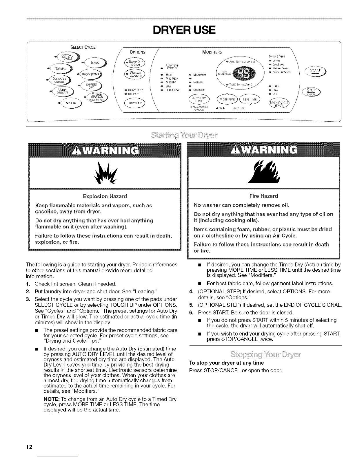
DRYER USE
MODIFIERSSELECT CYCLE / OPTIONS
_FUCAT_ _tJSTO_11_ _ DELICATE
/
/
AUTO ]EMP
CONTROL
HIGH
MED HIGH
MEDIUM
LOW
UE[RA LOW
o MAXIMUM
NORMAL
@
MINIMUM
U_,PAMO/STU_,/?
_UtSH_;
i!i _,T:
Explosion Hazard
Keep flammable materials and vapors, such as
gasoline, away from dryer.
Do not dry anything that has ever had anything
flammable on it (even after washing).
Failure to folow these instructions can resuR in death,
explosion, or fire.
The following is a guide to starting your dryer. Periodic references
to other sections of this manual provide more detailed
information.
1. Check lint screen. Clean if needed.
2. Put laundry into dryer and shut door. See "Loading."
3. Select the cycle you want by pressing one of the pads under
SELECT CYCLE or by selecting TOUCH UP under OPTIONS.
See "Cycles" and "Options." The preset settings for Auto Dry
or Timed Dry will glow. The estimated or actual cycle time (in
minutes) will show in the display.
• The preset settings provide the recommended fabric care
for your selected cycle. For preset cycle settings, see
"Drying and Cycle Tips."
• Ifdesired, you can change the Auto Dry (Estimated) time
by pressing AUTO DRY LEVEL until the desired level of
dryness and estimated dry time are displayed. The Auto
Dry Level saves you time by providing the best drying
results in the shortest time. Electronic sensors determine
the dryness level of your clothes. When your clothes are
almost dry, the drying time automatically changes from
estimated to the actual time remaining in your cycle. For
details, see "Modifiers."
NOTE: To change from an Auto Dry cycle to a Timed Dry
cycle, press MORE TIME or LESS TIME. The time
displayed will be the actual time.
Fire Hazard
No washer can completely remove oil.
Do not dry anything that has ever had any type of oi on
it (including cooking ois).
Reins containing foam, rubber, or pBastic must be dried
on a cmothesine or by using an Air Cycle.
Failure to folow these instructions can result in death
or fire.
• If desired, you can change the Timed Dry (Actual) time by
pressing MORE TIME or LESS TIME until the desired time
is displayed. See "Modifiers."
• For best fabric care, follow garment label instructions.
4. (OPTIONAL STEP) If desired, select OPTIONS. For more
details, see "Options."
5. (OPTIONAL STEP) If desired, set the END OF CYCLE SIGNAL.
6. Press START. Be sure the door is closed.
• Ifyou do not press START within 5 minutes of selecting
the cycle, the dryer will automatically shut off.
• Ifyou wish to end your drying cycle after pressing START,
press STOP/CANCEL twice.
To stop your dryer at any time
Press STOP/CANCEL or open the door.
12
Page 13

i!:::i_';iz!::i_jik_ji_!!!ii_iiii_i!_!i:iZi!_::iii¢_¸i::::i_;%!!!i!i_:_/:::ii!!;ii_ii!i:ii_ii_i_!!iiii_il;
To pause the dryer at any time
Open the door or press STOP/CANCEL once.
To restart the dryer
Close the door and press START.
NOTE: Drying will continue from where the cycle was interrupted
if you close the door and press START within 5 minutes. If the
cycle is interrupted for more than 5 minutes, the dryer will shut
off, You will need to select new cycle settings before restarting
the dryer.
Properly loading your dryer can lower your utility bill and prolong
the life of your garments.
Loading suggestions
• Load the dryer by the amount of space items take up, not by
their weight.
• Do not overload the dryer. This causes uneven drying and
wrinkling.
KING SIZE TM Capacity Dryers
Heavy Work Clothes
4 jeans 2 sweatpants
4 workpants 2 sweatshirts
4 workshirts
Towels
10 bath towels
10 hand towels
14 washcloths
Mixed Load
3 sheets (1 king, 2 twin) 9 T-shirts
4 pillowcases 9 shorts
3 shirts 10 handkerchiefs
3 blouses
Select the correct cycle and temperature for your load,
The display shows the estimated cycle time when your dryer is
automatically sensing the dryness level of your load. If a cycle is
using Timed Dry, the display shows the exact number of minutes
remaining in the cycle.
Cool Down tumbles the load without heat during the last few
minutes of all cycles, Cool Down makes the loads easier to
handle, The length of the Cool Down depends on the load size
and dryness level.
Drying tips
• Follow care label directions when they are available.
• If you use fabric softener sheets, use only ones labeled as
dryer safe. Follow package instructions.
• Remove the load from the dryer as soon as tumbling stops to
reduce wrinkling. This is especially important for permanent
press, knits, and synthetic fabrics.
Cycle tips
• Dry most loads using the preset cycle settings.
Use this chart as a guide to dry various loads. Drying
temperature and Auto Dry Level (Normal Dry) are preset when
you choose an Auto Dry cycle. You can select a different
dryness level, depending on your load (see "Modifiers").
For a Timed cycle, drying temperature is preset, but the time
can be adjusted.
PRESET CYCLE SETTINGS
Cycle Drying Temp. Time
Load Type Method (minutes)
(Auto Dry
Level)
COTTON/ Auto Dry High 54*
TOWELS (Normal)
Heavyweight
items, towels
JEANS Auto Dry Medium
Denim pants, (Normal) High
jackets
64*
NORMAL Auto Dry
Corduroys, (Normal)
work clothes
Medium 52*
BULKY Auto Dry
ITEMS (Normal)
Bedspreads,
sleeping bags
Medium 60*
DELICATE/ Auto Dry
CASUAL (Normal)
Sheets,
permanent
press, diapers
Low 36*
ULTRA Auto Dry
DELICATE (Normal)
Exercise wear,
sheer curtains,
lace
Ultra Low 22*
EXPRESS
DRY TM
Smafl loads
Timed Dry High 23**
AIR DRY
Rubber,
plastic,
special-care
Timed Dry No heat 30**
TOUCH UP Timed Dry
Heavy Duty High 30**
Heavyweight,
sturdy fabrics
Delicate Low 20**
Lightweight
items,
synthetics
*Estimated preset time
**Actual time
13
Page 14

Follow the progress of your dryer with the Drying Status
indicators.
DRYER STATUS
w DBYING
o COOL DOWN
WRINKLE GUARD
CHECK LINT SCREEN
DRYING glows when Start is pressed.
DRYING flashes when the display shows the actual minutes
remaining in the cycle. DRYING stops flashing at the start of Cool
Down.
COOL DOWN glows during the cool down part of the cycle.
CHECK LINT SCREEN flashes to remind you to clean the lint
screen before starting a cycle. The light turns off when you open
the dryer door or press Start.
Indicator lights
Other indicator lights show what cycle, options and modifiers
have been selected. The display lights also show the estimated
or actual Time Remaining.
Select the drying cycle that matches the type of load you are
drying. A preset range of heat is automatically set for the type of
fabric selected. (See "Drying and Cycle Tips" chart.)
When you select a cycle, your dryer selects a preset temperature,
Auto Dry Level (Normal) and either Auto Dry (Estimated) or Timed
Dry (Actual) Time Remaining. The time displayed for the Auto Dry
cycles are estimated times. Part way through the cycle, the dryer
turns the Auto Dry (Estimated) Time Remaining indicator light off
and displays the actual time remaining on the display. The Timed
Dry (Actual) indicator light will glow only if a Timed Dry cycle was
selected. (See "Modifiers.")
SELECT CYCLE
®(
Cotton/Towels
Use this cycle to get high heat for heavy fabrics.
Jeans
Use this cycle to get medium high heat for drying denims.
Normal
Use this cycle to get medium heat for drying sturdy fabrics.
Bulky Items
Use this cycle for drying large, bulky items that dry quickly on the
outside, but stay wet on the inside. This cycle uses medium heat.
Delicate/Casual
Use this cycle to get low heat for drying synthetic fabrics,
washable knit fabrics and no-iron finishes.
Ultra Delicate
Use this cycle to get ultra low heat to gently dry items such as
exercise wear or sheer curtains.
EXPRESS DRY TM
Use this 23 minute High Heat cycle for drying small loads or
loads that need a short drying time.
Air Dry
Air Dry gives you all the benefits of hang drying with a shorter
drying time. Adjust the Air Dry cycle from 1 to 99 minutes at any
time during the cycle, or use the preset setting of 30 minutes.
Use the Air Dry cycle for items that require drying without heat
such as rubber, plastic and heat-sensitive fabrics. This chart
shows examples of items that can be dried using the Air Dry
cycle.
Type of Load Minutes
Foam rubber - pillows, padded bras, stuffed toys 20 - 30
Plastic - Shower curtains, tablecloths 20 - 30
Rubber-backed rugs 40 - 50
Olefin, polypropylene, sheer nylon 10 - 20
When using Air Dry
• Check to see that coverings are securely stitched.
• Shake and fluff pillows by hand periodically during the cycle.
• Dry item completely. Foam rubber pillows are slow to dry.
NOTE: An Auto Dry Level selection is not available when using
the Air Dry cycle.
Custom Program
Use the Custom Program to select the Cycle, Options and
Modifiers you use most frequently and store them for future use.
To store a cycle for future use
1. Select a Cycle.
2. Select the desired Options.
3. Select the desired Modifiers.
4. Press and hold CUSTOM PROGRAM for 3 seconds until you
hear a beep.
5. Press START.
To reuse this cycle
1. Press CUSTOM PROGRAM.
2. Press START.
14
Page 15

You can customize your cycles by selecting options.
OPTIONS
@
o HEAVYDUTY
DELICATE
@
Damp Dry Signal
Select the Damp Dry Signal to alert you that your clothes are
approximately 80% dry. This is useful when you want to remove
lightweight items in a mixed load (to prevent overdrying), or
remove partially dry items that may need ironing.
NOTE: The Damp Dry Signal is an option that is only available
with Automatic cycle.
WRINKLE GUARD _ III
WRINKLE GUARD ®III prevents wrinkles that form when you
cannot unload the dryer promptly at the end of a cycle.
• Press WRINKLE GUARD _ III to get up to 21/2hours of heat-
free, periodic tumbling at the end of a cycle.
• Stop WRINKLE GUARD ®III at any time by pressing the
WRINKLE GUARD _ III pad or opening the dryer door.
For the Delicate/Casual Auto Dry cycle, WRINKLE GUARD _III
is preset to "ON." The other Auto Dry cycles will retain the
WRINKLE GUARD _ III setting. (For example, if you select
WRINKLE GUARD ®III in the Normal cycle, WRINKLE
GUARD _ III will be on the next time you select the Normal
cycle.)
NOTE: If you do not select WRINKLE GUARD ®III, the dryer stops
after Cool Down.
Touch Up
Select this option to remove wrinkles from clean items such as
clothes packed in a suitcase or items wrinkled from being left in
the dryer too long.
• Press TOUCH UP once to get HEAVY DUTY (30 minutes of
high heat). Use Heavy Duty for medium to heavyweight items
such as bedspreads and jeans.
• Press TOUCH UP twice to get DELICATE (20 minutes of low
heat). Use Delicate for light to medium weight items such as
blouses and skirts.
• Press MORE TIME or LESS TIME to adjust the cycle time.
• The WRINKLE GUARD ®III option is also available in Touch
Up. Remove clothes immediately when tumbling stops.
When you select a cycle, the preset Auto Dry Level (Auto Dry) or
Timed Dry settings for that cycle will glow. Modifiers allow you to
change the preset settings and further customize your cycles.
Auto Dry Level with Ultra Moisture Sensing
Auto Dry Level with Ultra Moisture Sensing provides the most
accurate drying results in the shortest time. This can help you
save money on utility bills and reduce the risk of fabric damage.
Dryness level is determined by dual sensor strips that measure
the moisture in your clothes. Once the desired dryness level is
reached, the electronic sensors signal the dryer to stop to
prevent overdrying your clothes.
MAXIMUM
NORMAL
MiNiMUM
ULfRAMO/STORE
SLNS/NO
NiGH
LOW
_0R_ TIMEODRY
For all Auto Dry cycles, the Auto Dry Level is automatically set at
Normal. This setting provides the recommended fabric care for
your cycle. The display will show the estimated time (in minutes)
required to reach an approximate 80% dry level. After the 80% .....
dryness level is reached, the remaining drying time required will
be displayed as actual time remaining.
Use the Normal setting to dry most loads. At the end of the cycle,
feel the dried clothes.
• If they are damper than you like, select a setting above
Normal the next time you dry a similar load.
• If they are drier than you like, select a setting below Normal
the next time you dry a similar load.
To change the dryness level
Press AUTO DRY LEVEL until the desired dryness level glows.
NOTE: Auto Dry Level is not a selectable option with the
EXPRESS DRY TM cycle, the Air Dry cycle or Touch Up.
To change from estimated to actual drying time
Press MORE TIME or LESS TIME until the desired time is
displayed. The light for Timed Dry (Actual) will glow.
Timed Dry
Use Timed Dry to select a specific amount of drying time. The
preset settings for EXPRESS DRYTM, Air Dry and Touch Up are
automatically set to Timed Dry.
To change the time
Press MORE TIME or LESS TIME until the desired time shows in
the display.
End of Cycle Signal
The End of Cycle Signal produces an audible sound when the
drying cycle is finished. Promptly removing clothes at the end of
the cycle reduces wrinkling.
Press the END of CYCLE SIGNAL pad to adjust the sound level
or turn off the signal.
NOTE: When WRINKLE GUARD ®III is selected and the End of
Cycle Signal is on, an audible sound will emit every five minutes
until the clothes are removed, or WRINKLE GUARD ®III is
finished.
15
Page 16

You can change Cycles, Options and Modifiers anytime before
Start is pressed.
• A short tone sounds when a change is selected.
• Two short tones sound if an unavailable combination is
selected. The last selection will not be accepted.
Changing Cycles after pressing Start
1. Press STOP/CANCELtwice.
2. Select the desired cycle.
3. Press START. The dryer starts at the beginning of the new
cycle.
NOTE: If you do not press Start within 5 minutes of selecting the
cycle, the dryer automatically shuts off.
Changing Options and Modifiers after pressing Start
You can change an Option or Modifier anytime before the
selected Option or Modifier begins.
1. Press STOP/CANCEL.
2. Select the new Option and/or Modifiers.
3. Press START to continue the cycle.
The dryer rack was shipped on top of your dryer. Remove and
discard shipping blocks before use.
Use the TUMBLE FREETM Heated Dryer Rack for items that you
do not want to tumble dry, such as sweaters. When you use the
heated dryer rack, the heated air inside the dryer flows in a
concentrated pattern to allow efficient and uniform drying.
Use Timed Dry to select the desired time.
NOTE: Do not use Automatic cycles with the dryer rack.
To use the heated dryer rack:
Do not remove the lint screen.
1. Open dryer door.
2. Slide dryer rack over the bottom of the dryer door opening.
Push down to secure on the frame.
3. Place wet items on top of the rack. Allow space around items
for air to circulate. The rack does not move, but the drum will
rotate. Make sure items do not hang over the edges or
between rack grille.
4. Close the door.
5. Select the desired cycle to match the fabrics in your load.
Items containing foam, rubber, or plastic must be dried on a
clothesline or by using an air cycle. Refer to the following
table.
6. You must select a time by pressing the MORE TIME or LESS
TIME pads. Refer to the following table.
7. Start the dryer.
NOTE: You must remove rack for normal tumbling. To remove the
dryer rack, lift it straight up and out of the dryer.
NOTE: Check the lint screen and remove any lint accumulated
from items dried on the rack.
Suggested Items for Rack Cycle Suggested
Drying Setting Time*
(minutes)
Washable wool items Touch Up 20
(block to shape and lay flat (Delicate)
on rack)
Stuffed toys or pillows Touch Up 30
(cotton or polyester (Delicate)
fiber filling)
Stuffed toys Air Dry 50
(foam rubber filled)
Tennis shoes Air Dry 20
* Reset time as needed to complete drying.
DRYER CARE
Keep dryer area clear and free from items that would obstruct the
flow of combustion and ventilation air.
E×plosion Hazard
Keep flammabBe materiams and vapors, such as
gasoline, away from dryer.
Place dryer at least 18 inches (46 cm) above the floor
for a garage installation.
Failure to do so can resuJt in death, e×plosion, or fire.
16
Page 17

Every load cleaning
The lint screen is located in the door of the dryer. Clean it before
each load. A screen blocked by lint can increase drying time.
To clean
1. Pull the lint screen straight up. Roll lint off the screen with
your fingers. Do not rinse or wash screen to remove lint. Wet
lint is hard to remove.
J
2. Push the lint screen firmly back into place.
IMPORTANT:
• Do not run the dryer with the lint screen loose, damaged,
blocked, or missing. Doing so can cause overheating and
damage to both the dryer and fabrics.
Some towels made of synthetic fibers and natural fibers
(polyester and cotton blends) may shed more lint than other
towels, causing your dryer's lint screen to fill up faster. Be
sure to remove lint from the lint screen before and after drying
new towels.
• If lint falls off the screen into the dryer during removal, check
the exhaust hood and remove the lint. (See "Venting
Requirements.")
As needed cleaning
Laundry detergent and fabric softener residue can build up on the
lint screen. This buildup can cause longer drying times for your
clothes, or cause the dryer to stop before your load is completely
dry. The screen is probably clogged if lint falls off the screen.
Clean the lint screen with a nylon brush every 6 months or more
frequently if it becomes clogged due to a residue buildup.
To wash
1. Roll lint off screen with your fingers.
2. Wet both sides of lint screen with hot water.
3. Wet a nylon brush with hot water and liquid detergent. Scrub
lint screen with the brush to remove residue buildup.
4. Rinse screen with hot water.
5. Thoroughly dry lint screen with a clean towel. Replace screen
in dryer.
To clean the dryer drum
1. Make a paste with powdered laundry detergent and very
warm water.
2. Apply paste to a soft cloth.
OR
Apply a liquid, nonflammable household cleaner to the
stained area and rub with a soft cloth until all excess dye is
removed.
3. Wipe drum thoroughly with damp cloth.
4. Tumble a load of clean cloths or towels to dry the drum.
NOTE: Garments which contain unstable dyes, such as denim
blue jeans or brightly colored cotton items, may discolor the
interior. These stains are not harmful to your dryer and will not
stain future loads of clothes. Dry unstable dye items inside out to
prevent dye transfer.
From Inside the Dryer Cabinet:
Lint should be removed every 2 years or more often, depending
on dryer usage. Cleaning should be done by a qualified person.
From the Exhaust Vent:
Lint should be removed every 2 years, or more often, depending
on dryer usage.
Vacation care
Operate your dryer only when you are at home. If you will be on
vacation or not using your dryer for an extended period of time,
you should:
1. Unplug dryer or disconnect power.
2. Close shutoff valve in gas supply line.
3. Clean lint screen. See "Cleaning the Lint Screen."
Moving care
1. Unplug dryer or disconnect power.
2. Close shutoff valve in gas supply line.
3. Disconnect gas supply line pipe and remove fittings attached
to dryer pipe.
4. Cap the open fuel supply line.
5. Make sure leveling legs are secure in dryer base.
6. Use masking tape to secure dryer door.
The dryer light automatically turns on inside the dryer drum when
you open the door.
To change the drum light
1. Unplug dryer or disconnect power.
2. Open the dryer door. Locate the light bulb cover on the back
wall of the dryer. Remove the screw located in the lower right
corner of the cover. Remove the cover.
3. Turn bulb counterclockwise. Replace the bulb only with a
10-watt appliance bulb. Replace the cover and secure with
the screw.
4. Plug in dryer or reconnect power.
17
Page 18

TROUBLESHOOTING
First try the solutions suggested here and possibly avoid the cost of a service call.
Dryer displaying code message Dryer will not run
• "PF" (power failure), check the following:
Is the dryer connected to the power supply?
• Check the following:
Is the power cord plugged in?
Was the dryer connected to a power supply during
installation or a power failure?
Press STOP/CANCEL to clear display.
Was the drying cycle interrupted by a power failure?
Press START to restart the dryer.
Has a fuse blown, or has a circuit breaker tripped?
Was a regular fuse used? Use a time-delay fuse.
Is the dryer door firmly closed?
Was the START button firmly pressed?
• "E" Variable (El, E2, E3) service codes: Is a cycle selected?
Call for service.
Clothes are not drying satisfactorily
• Checkthe following:
Is the lint screen clogged with lint?
Unusual sounds
• Has the dryer had a period of non-use?
If the dryer hasn't been used for a while, there may be a
thumping sound during the first few minutes of operation.
Is the exhaust vent or outside exhaust hood clogged with lint,
restricting air movement? Run the dryer for 5-10 minutes.
Hold your hand under the outside exhaust hood to check air
movement. If you do not feel air movement, clean exhaust
system of lint or replace exhaust vent with heavy metal or
flexible metal vent. See "Installation Instructions."
Is the exhaust vent crushed or kinked? Replace with a heavy
metal or flexible metal vent. See "Installation Instructions."
Has a fuse blown, or has a circuit breaker tripped?
Has an Air Dry cycle been selected? Select the right cycle for
the types of garments being dried. See "Cycles."
The gas valve clicking is a normal operating sound.
Lint on load
• Is the lint screen clogged?
Clean lint screen. Check for air movement.
• Is load properly sorted?
Sort lint givers (towels, chenille) from lint takers (corduroy,
synthetics). Also sort by color.
• Is the load too big or too heavy?
Dry smaller loads so lint can be carried to the lint screen.
Is the automatic cycle ending early? The load may not be
contacting the electronic sensor strips, level the dryer.
Is the valve open on the gas supply line?
Are fabric softener sheets blocking the grille? Use only one
fabric softener sheet and only use it once.
Is the dryer located in a room with temperature below
45°F (7°C)?
Proper operation of dryer cycles requires temperatures above
45°F (7°C).
Was a cold rinse water used? Was the load very wet?
Expect longer drying times with items rinsed in cold water
and with items that hold moisture (cottons).
Is the load too large and heavy to dry quickly?
Separate the load to tumble freely.
Was the load overdried?
Use correct dryer settings for load type. See "Changing
Cycles, Options and Modifiers." Overdrying can cause
lint-attracting static electricity.
Was paper or tissue left in pockets?
Is pilling being mistaken for lint?
Pilling (surface fuzz) is caused by normal wear and
laundering.
Stains on load or color change
Was dryer fabric softener properly used?
Add dryer fabric softener sheets at the beginning of the cycle
when the load is cold. Do not add fabric softener sheets to a
warm load.
• Were items soiled when placed in the dryer?
Items should be clean before being dried.
• Were items properly sorted?
Sort light colors from dark colors. Sort colorfast items from
noncolorfast items.
18
Page 19

Items shrinking
• Was the dryer overloaded?
Dry smaller loads that can tumble freely.
• Did the load overdry?
Check the manufacturer's care label. Match dryer setting to
load type. See "Cycles."
Loads are wrinkled
• Was load removed from dryer at the end of the cycle?
• Was dryer overloaded?
Dry smaller loads that can tumble freely.
• Did load overdry?
Check the manufacturer's care label. Match dryer setting to
load type. See "Cycles."
Odors
• Have you recently been painting, staining or varnishing in
the area where your dryer is located?
If so, ventilate the area. When the odors or fumes are gone
from the area, rewash and dry the clothing.
Garment damage
• Check the following:
Were zippers, snaps, and hooks left open?
Were strings and sashes tied to prevent tangling?
Were care label instructions followed?
Were items damaged before drying?
19
Page 20

iNDICE
CONTRATOS DE PROTECCION ................................................ 20
GARANTIA .................................................................................... 21
SEGURIDAD DE LA SECADORA ............................................... 22
INSTRUCCIONES DE INSTALACION ........................................ 23
Herramientas y piezas ............................................................... 23
Requisites de ubicaci6n ............................................................ 24
Requisites electricos ................................................................. 25
Requisitos del suministro de gas .............................................. 25
Requisites de ventilaci6n .......................................................... 27
Planificaci6n del sistema de ventilaci6n ................................... 27
Instalaci6n del sistema de ventilaci6n ...................................... 29
Instalaci6n de las patas niveladoras ......................................... 29
Nivelaci6n de la secadora ......................................................... 30
Conexi6n del suministro de gas................................................ 30
Conexi6n del ducto de escape ................................................. 30
Complete la instalaci6n ............................................................. 30
USO DE LA SECADORA ............................................................. 31
Puesta en marcha de su secadora ........................................... 31
C6mo detener su secadora ....................................................... 32
C6mo hacer una pausa o reanudar la marcha ......................... 32
C6mo cargar .............................................................................. 32
Sugerencias de ciclos y de secado .......................................... 32
Estado de la secadora (Dryer Status) ....................................... 33
Ciclos ......................................................................................... 33
Opciones ................................................................................... 34
Modificadores ............................................................................ 35
Cambio de ciclos, opciones y modificadores ........................... 35
Estante termico de la secadora TUMBLE FREETM ................... 36
CUIDADO DE LA SECADORA .................................................... 36
Limpieza del lugar donde esta
la secadora ................................................................................ 36
Limpieza del filtro de pelusa ...................................................... 36
Limpieza del interior de la secadora ......................................... 37
Eliminaci6n de pelusa acumulada ............................................ 37
Cuidado para las vacaciones y
la mudanza ................................................................................ 37
Cambio de la luz del tambor ..................................................... 37
SOLUCION DE PROBLEMAS ..................................................... 38
NUMEROS DE SERVICIO .............................. CONTRAPORTADA
CONTRATOS DE
PROTECCION
Contratos Maestros de Proteccibn
iFelicitaciones per su inteligente adquisici6n! Su nuevo producto
Kenmore ®ha sido diser_ado y fabricado para brindarle argos de
funcionamiento confiable. Pero al igual que todos los productos,
puede necesitar mantenimiento preventivo o reparaci6n de vez
en cuando. Es allf donde el Contrato Maestro de Protecci6n
puede ahorrarle dinero e inconvenientes.
Adquiera un Contrato Maestro de Protecci4n hey y prot_jase
contra molestias y gastos inesperados.
El Contrato Maestro de Proteccidn tambien ayuda a prolongar la
vida de su nuevo producto. He aquf Io que se incluye en el
Contrato:
v' Servicio experto por nuestros 12.000 especialistas en
reparaci6n competentes
v' Servicio ilimitado y gratuito para repuestos y mane de obra
en todas las reparaciones protegidas por el contrato
v' Garantia "sin disgustos" - reemplazo de su producto
protegido si ocurren cuatro o mas fallas del producto en el
transcurso de doce meses
v' Reemplazo del producto si su producto protegido no puede
ser reparado
v' Revisibn Anual de Mantenimiento Preventivo a solicitud
suya - sin costo adicional
v"
Ayuda r_pida por tel_fono - asistencia per telefono a cargo
de un tecnico de Sears para productos que deban ser
reparados en su hogar, ademas de un horario de reparaci6n
conveniente
v' Proteccibn de sobrevoltaje contra dados electricos debido a
fiuctuaciones de electricidad
v' Reembolso de la renta si la reparaci6n de su producto
protegido tarda mas de Io prometido
Una vez adquirido el Contrato, tan s61otiene que Ilamar para fijar
la visita de servicio tecnico, Usted puede Ilamar a cualquier hora,
de dia o de noche, o fijar una visita tecnica en internet.
Sears cuenta con un equipo de mas de 12.000 especialistas en
reparaci6n competentes, quienes tienen a disposici6n mas de
4,5 millones de repuestos y accesorios de calidad. Cse es el tipo
de profesionalismo con el que usted puede contar para ayudarle
a prolongar la vida de su nuevo artefacto per muchos a_os mas.
iAdquiera hey su Contrato Maestro de Protecci6n!
Se aplican algunas limitaciones y exclusiones. Para obtener
precios e informaci6n adicional, Ilame al 1-800-827-6655.
Servicio de Instalacibn de Sears
Para la instalaci6n profesional de Sears de artefactos
electredomestices, abridores de puertas de garaje, calentadores
de agua y otros articulos importantes de la casa, en los EE.UU.
Ilame al 1-800-4-MY-HOME ®.
20
Page 21

GARANTIA
Garantia completa de un aho para las piezas mec&nicas y
componentes el_ctricos
Durante un a_o a partir de la fecha de compra, si se instala y
pone en funcionamiento la secadora de conformidad con las
instrucciones proporcionadas en este Manual de Uso y Cuidado,
Sears reparara esta secadora, gratuitamente, si tuviese defectos
en el material o la mano de obra.
NOTA: El empleo de un ducto de escape de plastico para esta
secadora puede anular esta garantia. Consulte la secci6n de
"lnstrucciones de instalaci6n" para obtener informaci6n
completa sobre los requisitos de ventilaci6n para esta secadora.
Garantia limitada de dos ahos para el tablero de control
electrbnico SENSOR SMART TM
Durante el segundo a_o a partir de la fecha de compra, Sears
reemplazara el tablero de control electr6nico si tuviese defectos
de materiales o de mano de obra. El cliente se hara cargo de los
gastos de mano de obra despues del primer aSo.
Restriccibn de la garantia
Si se somete a esta secadora a un uso ajeno al domestico
privado, la cobertura de las garantfas arriba citadas quedan
restringidas a s61o 90 dias.
Servicio de reparacibn de la garantia
El servicio de reparaci6n de la garantia esta a su disposici6n al
contactarse con el Centro de Servicio Sears mas cercano. Esta
garantia corresponde s61o mientras se use el producto en los
Estados Unidos.
Esta garantia le otorga derechos legales especificos yes posible
que usted tenga tambien otros derechos que pueden variar de un
estado a otro.
Para obtener informaci6n respecto a la garantfa de Sears o para
ponerse en contacto con un Centro de Servicio de Sears, sfrvase
tomar como referencia los nQmeros de servicio tecnico ubicados
en la contraportada del manual.
Sears, Roebuck and Co.
D/817WA, Hoffman Estates, IL 60179
Registro del producto
Use el espacio a continuaci6n para anotar el nQmero completo
del modelo y de la serie, asi como la fecha de compra. Usted
podra encontrar esta informaci6n en la etiqueta con el nQmero de
modelo y de serie, en la cavidad interna superior de la puerta de
la secadora.
Siempre que se ponga en contacto con Sears respecto a su
electrodomestico, tenga esta informaci6n a mano para facilitar la
obtenci6n de ayuda o servicio tecnico.
Ni3mero de modelo 110.
Ni3mero de serie
Fecha de compra
Guarde estas instrucciones y su comprobante de ventas para
referencia futura.
21
Page 22

SEGURIDAD DE LASECADORA
Su seguridad y la seguridad de los demas es muy importante.
Heroes incluido muchos mensajes importantes de seguridad en este manual y en su electrodomestico. Lea y obedezca siempre
todos los mensajes de seguridad.
Este es el simbolo de advertencia de seguridad.
Este simbolo le llama la atencidn sobre peligros potenciales que pueden ocasionar la muerte o una lesidn a
usted y a los demas.
Todos los mensajes de seguridad iran a continuacion del sfmbolo de advertencia de seguridad y de la palabra
"PELIGRO" o "ADVERTENClA". Estas palabras significan:
Si no sigue las instrucciones de inmediato, usted puede
morir o sufrir una lesion grave.
Si no eigue las instrucciones, usted puede morir o sufrir
una lesion grave.
Todos los mensajes de seguridad le dir_.n el peligro potencial, le dir_.n cdmo reducir las posibilidades de sufrir una lesion y Io que
puede suceder si no se siguen las instrucciones.
ADVERTENCIA: Para su seguridad, la informacibn en este manual debe ser observada
para minimizar el riesgo de incendio o explosibn, o para prevenir dahos a propiedades,
heridas o la muerte.
- No almacene o use gasolina u otros liquidos y vapores inflamables cerca de dste u otro
aparato electrodomdstico.
- PASOS QUE USTED DEBE SEGUIR SI HUELE A GAS:
• No trate de encender ningdn aparato electrodomdstico.
• No toque ningdn interruptor eldctrico; no use ningdn teldfono en su edificio.
• Desaloje a todos los ocupantes del cuarto, edificio o area.
• Llame inmediatamente a su proveedor de gas desde el teldfono de un vecino.
Siga las instrucciones de su proveedor de gas.
• Si usted no puede comunicarse con su proveedor de gas, Ilame al departamento
de bomberos.
- La instalacibn y el servicio deben ser efectuados por un instalador calificado, una
agencia de servicio o por el proveedor de gas.
En el estado de Massachusetts se aplican las siguientes instrucciones de instalacidn:
Las instalaciones y reparaciones se deben efectuar per un contratista, plomero o gasista calificado o licenciado per el estado
de Massachusetts.
Si se usa una vatvula de bota, debe set un tipo de manigueta T.
Si se usa un conector de gas flexible no debe exceder de 3 pies.
22
Page 23

iNSTRUCCiONES iMPORTANTES DE SEGURIDAD
ADVERTENCUA: A fin de reducir el riesgo de incendio, descarga electrica o de dane a Ias personas que usen
la secadora, deben seguirse las precauciones basicas, incluidas las siguientes:
• Lea todas las instrucciones antes de usar la secadora.
• No coloque Ios objetos expuestos a aceite para cocinar
en su secadora. Los obietos expuestos a aceites para
cocinar pueden contribuir a una reacci6n quimica que
podria causar que una carga se inflame.
• No seque articulos que ya se hayan limpiado, lavado,
remojado o manchado con gasolina, disolventes de
Iimpieza en seco, u otras sustancias infiamables o
explosivas ya que despiden vapores que pueden
encenderse o causar una explosi6n.
• No permita que jueguen Ios ni¢ios sobre o dentro de la
secadora. Es necesaria la cuidadosa vigilancia de los
nifios toda vez que se use la secadora cerca de elIos.
• Quite la puerta de la secadora al compartimiento de secado
antes de ponerla fuera de funcionamiento o de descartaria.
• No introduzca Ias manos en Ia secadora cuando el tambor
esta en movimiento.
• No instale o almacene esta secadora donde estara
expuesta a agua o a Ia intemperie.
• No trate de forzar los controles.
• No repare o reemptace ninguna pieza de Ia secadora ni
trate de repararia a menos que esto se recomiende
especificamente en ei Manual de! propietario o en
instrucciones de reparaci6n publicadas para eI usuario
que usted comprenda y s61osi cuenta con la experiencia
necesaria para Ilevar a cabo dicha reparaci6n.
• No utilice suavizadores de teiidos o productos para eliminar
el estatico de prendas a menos que Io recomiende e!
fabricante del suavizador de teiidoso las instrucciones del
producto en uso.
• No utilice calor para secar prendas que contengan espuma
de caucho o matedales de caucho con textura similar.
• Limpie eI filtro de pelusa antes o depues de cada carga
de ropa.
• Mantenga el area alrededor de Ia apertura de ventilaci6n
y Ias areas adyacentes a esta apertura sin pelusa, polvo
o tierra.
• La parte interior de la secadora yet ducto de escape se
deben limpiar peri6dicamente. Esta Iimpieza Ia debe lievar
a cabo un reparador calificado.
• Vea la instrucciones de instalaci6n para los requisitos de
conexi6n a tierra.
GUARDE ESTAS iNSTRUCCiONES
IMPORTANTE: La instalaci6n de gas debe hacerse de acuerdo con los c6digos locales, o si no los hay, con el C6digo Nacional
de Gas Combustible (National Fuel Gas Code), ANSI Z223.1/NFPA 54.
La secadora debe estar conectada a tierra de acuerdo con los c6digos locales, o si no los hay, con el C6digo Nacional de
Electricidad (National Electrical Code), ANSI/NFPA 70.
INSTRUCCIONES DE INSTALACION
Verifique si tiene todo Io necesario para una instalaci6n correcta.
La instalaci6n adecuada es responsabilidad suya.
Llave para tubos de 8" 6
10"
Llave de tuercas
ajustable de 8" 6 10"
(para conexiones de gas)
Destornillador de hoja
plana
Llave de tuercas
ajustable que se abra a
1" (2,5 cm) o una Ilave de
cube de cabeza
hexagonal (para regular
las patas de la secadora)
• Nivel
• Llave para tuercas de V4"
o Ilave de cubo
• Cuchillo
• Abrazaderas para ducto
• Pegamento paratuberfas
resistente a gas L.R
• Pistola y masilla para
calafateo (para instalar el
nuevo ducto de escape)
• Alicates
Piezas suministradas:
Retire el paquete de piezas del tambor de la secadora. Verifique
que esten todas las piezas.
4patas niveladoras
Piezas para adquirir:
Verifique los c6digos locales y con la compafiia abastecedora de
gas, verifique el suministro de gas existente, el suministro
electrico y la ventilacidn y lea "Requisitos electricos", "Requisitos
de suministro de gas" y "Requisites de ventilacidn" antes de
comprar las piezas.
Las instalaciones en casas rodantes requieren piezas especiales
(enlistadas a continuaci6n) disponibles para la compra en su
tienda local de Sears o en un Centro de servicio Sears. Para mas
informaci6n, Ilame por favor al 1-800-4-MY-HOME ®
(1-800-469-4663).
• Juego de instalaci6n para casas rodantes. Pida la pieza
nOmero 346764.
• Herramientas para el sistema de ventilaci6n de metal.
23
Page 24

iii:::i_=O=(i::ilLiiiilS;iiiii:OS(!]i!i!i!@LtL)ii(i:]_iiii:tOiii(ii!!iii
Peligro de E×plosi6n
Mantenga los materiales y vapores inflamables, come
la gaeolina, lejos de la eecadora.
Coloque la secadora a un minimo de 48 cm eobre
el piso para la instalaci6n en un garajeo
No seguirestas instruccionespuede ocasionar
lamuerte,e×plesion o incendio°
Usted necesitar_
• Una Iocalizaci6n que permita una instalaci6n adecuada del
ducto de escape. Una secadora a gas debe tener una salida
de ventilaci6n hacia el exterior. Consulte "Requisites de
ventilaci6n".
• Un contacto con conexi6n atierra ubicado a un max(me de
2 pies (61 cm) de cualquiera de los lades de la secadora. Vea
"Requisites electricos".
• Un piso resistente para soportar la secadora con un peso
total (secadora y carga) de 200 Ibs (90,7 kg).
Un piso nivelado con un declive max(me de 1" (2,5 cm)
debajo de la secadora completa. (Si el declive es mayor que
1" [2,5 cm], instale el juego de extensiTn de patas de la
secadora, Pieza No. 279810.) La ropa quizas no rote
adecuadamente y los ciclos del sensor automat(co
posiblemente no funcionen debidamente si la secadora no
esta nivelada.
No ponga a funcionar su secadora en un lugar cuyas
temperaturas sean infer(ores a 45°F (7°C). A temperaturas
infer(ores, es posible que la secadora no se apague al final de un
ciclo automat(co. Los tiempos de secado pueden prolongarse.
No debe instalarse ni guardarse la secadora en un area en donde
pueda estar expuesta al agua y/o a la intemperie.
Verifique los requisites de los c6digos. Algunos c6digos limitan, o
no permiten, la instalaciTn de la secadora en garajes, clTsets,
casas rodantes o en dormitories. P6ngase en contacto con el
inspector de construcciones de su local(dad.
NOTA: No se puede instalar otro electrodomestico que use
combustible en el mismo cl6set en que se encuentra la secadora.
Espacios para la Instalacibn
La ubicaci6n debeser Io suficientemente grande para poder
abrir completamente la puerta de la secadora.
Dimensiones de la secadora
_&Scm)
* La mayoria de las instalaciones requieren un espacio minimo de
51/2''(14 cm) detras de la secadora para acomodar el ducto de
escape con code. Vea "Requisites de ventilaci6n".
Espacio rain(me para la instalaci6n en un lugar empotrado o
en un cl6set
Las siguientes dimensiones ilustradas son para el espacio
minimo permit(do.
• Debe considerarse el espacio adicional para facilitar la
instalaci6n y el servicio tecnico.
Se podrian necesitar espacios libres adicionales para las
molduras de la pared, de la puerta y del piso.
Se recomienda un espacio adicional de 1" (2,5 cm) en todos
los lades de la secadora para reducir la transferencia de
ruido.
Para la instalaciTn en clTset, con una puerta, se requieren
aberturas de ventilaci6n minimas en la parte superior e
inferior de la puerta. Se aceptan puertas tipo persianas con
aberturas de ventilaci6n equivalentes.
Tambien se debe considerar espacio adicional para otro
electrodomestico que le acompade.
I _] {_PI_ z_" max. _-_
18" (310 cm2 }
(45,7
24 pulg.2_
-- _ ._ (155crn2)
1"-_ _27" _ _1" _1"1__w'_15v="_
(2,5cm) (68,6 cm) (2,5 cm) (2_5cm)(74,3 cruX14 cm)
A B
_3"
(7,6 crn)
t
(7,6cm)
A. Lugar empotrado
B. Vista lateral - cldset o lugar conflnado
C. Puerta del cldset con orificios de ventilacidn
24
Page 25

Requisitos de instalacibn adicionales para las casas
rodantes
Esta secadora es apropiada para instalaciones en casas
rodantes. La instalaci6n debe ajustarse al Estandar de seguridad
y construcci6n de casas fabricadas, Tftulo 24 CFR, Parte 3280
(anteriormente conocido como Estandar federal para la
seguridad y construcci6n de casas rodantes, Tftulo 24, HUD
Parte 280).
Las instalaciones en casas rodantes necesitan:
• Herramientas del sistema de escape de metal, que se
encuentran disponibles para ser compradas en su tienda
Sears o en el distribuidor de servicio tecnico Sears de su
Iocalidad.
• Juego para la instalaci6n en casas rodantes, Pieza nQmero
346764. Vea la secci6n "Herramientas y piezas" para la
informaci6n sobre c6mo ordenar.
Se deben tomar medidas especiales en el caso de casas
rodantes para introducir el aire del exterior en la secadora. La
abertura (como la de una ventana adyacente) debera ser por
Io menos el doble de tama_o que la abertura de ventilaci6n
de la secadora.
Peligro de Choque Electrico
Conecte a un contacto de pared de cone×i6n a tierra de
3 terminales°
No quite emterminam de cone×i6n a tierra.
No use un adaptador.
No use un cable electrico de extenei6n.
No seguir estae instrucciones puede ocasionar
la muerte, incendio o choque emectrico.
Se necesita un suministro electrico de 120 voltios,
60 hertzios, CA solamente, de 15 6 20 amperios y protegido
con fusible. (Se recomienda el empleo de un fusible
retardador o cortacircuitos.) Asimismo se recomienda el uso
de un circuito independiente que preste servicio Qnicamente
a esta secadora.
INSTRUCCIONES PARA LA CONEXI6N A TJERRA
m Para Ia conexi6n de una secadora mediante cable
electrico conectado a tierra:
Esta secadora debe estar conectada a tierra. En el caso de
funcionamiento defectuoso o averia, la conexi6n a tierra
reducira el riesgo de choque electrico aI proporcionar una
via de menor resistencia para Ia corriente electrica. Esta
secadora est& equipada con un cable que cuenta con un
conductor para la conexi6n a tierra det equipo y un enchufe
de conexi6n a tierra= El enchufe debe conectarse en un
contacto apropiado, que este debidamente instalado y
conectado a tierra de acuerdo con todos los c6digos y
ordenanzas locales.
ADVERTENCmA: ha conexi6n indebida del
conductor para la conexi6n a tierra deI equipo puede
ocasionar un riesgo de choque electrico. Verifique con un
electricista, representante o personal de servicio tecnico
calificado para asegurarse de que la conexi6n a tierra de la
secadora sea apropiada. No modifique el enchufe
proporcionado con la secadora. Si no encaja en el contacto,
contrate un etectdcista calificado para que instale un
contacto adecuado.
GUARDE ESTAS INSTRUCCIONES
Pemigro de E×pmosi6n
Usa una m{neade surninietro de gas nueva con
aprobacion AGA o CSA°
tnstale una vatvu_a de cierre.
Apriete firmernente todas las cone×ionee de gas°
Si ee conecta a un surninietro de gas LOP°,mapresion no
debe exceder una coBurnna de agua de 33 crn (13 pumg.)
y debe set verificada pot una persona caHficada.
Ejernpios de una persona caBificada incluyen:
personal de eervicio demsieterna de calefaccion con
licencia,
persona{ autorizado de la compaSia de gas, y
personal autorizado para dar servicioo
No seguir estas instruccionee puede ocasionar
la muerte, expmosi6n o incendio°
Tipo de gas
Gas natural:
Esta secadora esta equipada para uso con gas natural. Su
dise_o esta certificado por la CSA Internacional para gases L.R
(de propano o butano) con la conversi6n apropiada.
25
Page 26

Su secadora debe tener el quemador adecuado para el tipo
de gas que tiene en su casa. La informaci6n respecto al
quemador esta ubicada en la placa de clasificaci6n que esta
en la cavidad de la puerta de su secadora. Siesta
informaci6n no esta de acuerdo con el tipo de gas disponible,
p6ngase en contacto con su tienda Sears o con el Centre de
Servicio Sears de su Iocalidad.
Conversi6n de gas L.P.:
La conversi6n debera Ilevarla a cabo un t_cnico calificado.
No se debera hacer intento alguno para convertir el uso del gas
especificado en la placa de clasificaci6n del modelo/de la serie
de este artefacto por el use de un gas distinto sin consultar con
el abastecedor de gas.
La linea de suministro de gas:
• Se recomienda un tubo IPS de 1/2".
• Si los c6digos locales y el proveedor de gas Io permiten, es
aceptable una tuberfa aprobada de %" para longitudes
menores a los 20 pies (6,1 m).
Debe incluir una derivaci6n tapada NTP de por Io menos 1/8"
accesible para la conexi6n del man6metro de prueba,
inmediatamente arriba de la conexi6n de suministro de gas a
la secadora (vea la ilustraci6n).
• Debe incluir una vMvula de cierre:
Debe instalarse una vMvula de cierre individual manual a una
distancia de un maximo de seis (6) pies (1,8 m) de la
secadora de acuerdo con el C6digo Nacional de Gas
combustible (National Fuel Gas Code), ANSI Z223.1. La
vMvula debera ubicarse en un lugar donde se pueda
alcanzar con facilidad para cerrarla y abrirla.
A C E
B D
A. Conector de gas flexible de %"
B.Accesorio adaptador abocinado de _"
C. Derivacidn tapada NPT de _"
D. Lfnea de suministro de gas NPT de 7/2"
E. Vblvula de cierre del gas
Requisitos para la conexibn del suministro de gas
Existen muchos metodos mediante los cuales puede conectar su
secadora a gas al suministro de gas. He aquf algunas directivas
para los dos metodos diferentes de conexidn.
Opcibn 1 (M_todo recomendado):
Conector de gas flexible de acero inoxidable:
Si los cddigos locales Io permiten, use un conector de gas
flexible nuevo de acero inoxidable (diser3o certificado per la
Asociacidn americana de gas o la CSA Internacional) para
conectar su secadora a la Ifnea rfgida de suministro de gas. Use
un codo y un accesorio adaptador abocinado NPT de %" por %"
entre el tube de acero inoxidable y el tube de gas de la secadora,
para evitar que se doblen.
Opcibn 2 (M_todo alternativo):
Tuberfa aprobada de aluminio o de cobre:
• Las longitudes inferiores a los 20 pies (6,1 m) pueden usar
una tuberia aprobada de 3/8"(si los c6digos y el abastecedor
de gas Io permiten).
• Si usted esta usando gas natural, no use tuberfa de cobre.
• Un adaptador abocinado NPT de %" por %" entre el tubo de
la secadora y la tuberia aprobada de %".
• Las longitudes superiores a los 20 pies (6,1 m) deberan usar
tuberias mas largas y un accesorio adaptador de tamaSo
distinto.
Si su secadora ha sido convertida para usar gas L.R, se
puede usar tuberia de cobre compatible de L.R de %". Si la
Iongitud total de la Ifnea de suministro es mayor que 20 pies
(6,1 m), use un tubo mas largo.
NOTA: Se deben usar pegamentos para uniones de tuberfas
que resistan la acci6n del gas L.R No use cinta de TEFLON%
El tubo de gas de la secadora
• El tube de gas que sale por la parte posterior de su secadora
tiene una conexi6n de filete macho de %".
A /
A. Lfnea de suministro de gas NPT de V2"
B. Tubo NPT de _" de la secadora
Requisitos de entrada del quemador:
Elevaciones por hasta los 10.000 pies (3.048 metros):
• El dise_o de esta secadora esta certificado por CSA
Internacional para uso en altitudes que alcanzan los 10.000
pies (3.048 m) sobre el nivel del mar en la categoria de B.T.U.
indicada en la placa del nOmero de modelo/serie. No se
requieren ajustes de entrada del quemador cuando se usa la
secadora a esta altitud.
Elevaciones encima de los 10.000 pies (3.048 metros):
• Si se instala la secadora a un nivel superior a los 10.000 pies
(3.048 m) de altitud, se requiere una reducci6n de categoria
de B.T.U. del 4% del quemador, que se muestra en la placa
del nOmero de modelo/serie, por cada incremento de 1.000
pies (305 m) de altitud.
Prueba de presibn del suministro de gas
• Durante pruebas de presi6n a presiones mayores de
1/2Ib/pulg =,la secadora debe set desconectada del sistema
de tuberia del suministro de gas.
1-®TEFLON es una mama registrada de E.I. Du Pont De Nemours and Company.
26
Page 27

iii::::i_,_!i!!_,(]:ilLiiiilS;ii!iiii:OSdi!i!@v@iiiiiii:ii!i!,_%Oii=_i:::i!il'l
Peligro de Incendie
Use un ducto de escape de metal pesade,
No use un ducto de escape de plasticoo
No use un ducto de escape de aluminio,
No seguir estas instrucciones puede ocasionar
Jamuerte o incendio.
ADVERTENCIA: Para reducir el riesgo de incendio, esta
secadora DEBE VENTILARSE HACIA EL EXTERIOR.
Se debe usar un ducto de escape de metal pesado de
4" (10,2 cm) y abrazaderas. Los productos de ventilaci6n
DURASAFE TM son recomendables y se encuentran disponibles
en la tienda Sears o el centre de servicio tecnico Sears de su
Iocalidad.
Los productos de ventilaci6n DURASAFE TM pueden adquirirse
de su distribuidor. Para mas informaci6n, per favor lame al
1-800-4-MY-HOME ®(1-800-469-4663} o visite nuestro sitio en la
internet en: www.sears.com.
La salida de la secadora no debe conectarse en ning0n ducto
de escape de gas, chimenea, pared, techo o el espacio
oculto de un edificio.
No use una capota de ventilaci6n con pestillo magnetico.
No instale el ducto de escape de metal flexible en paredes,
techos o pisos encerrados.
Utilice abrazaderas para sellar todas las juntas. No debe
conectarse ni asegurarse el ducto de escape con tornillos ni
ningQn otro dispositivo que se extienda hacia el interior de
dicho ducto. No utilice cinta adhesiva para conductos.
IMPORTANTE: Observe todas las normas y ordenanzas
vigentes,
La ventlaci6n inadecuada puede ocasionar Ja
acurnulaci6n de humedad y pelusa en la casa, Io cual
puede dar come resuttado:
[] DaSos de humedad en la carpinteria, muebJes, pintura,
empapelado, aJfombras, etc.
m Problemas en la/mpieza de la casa y de saJud.
Use un ducto de escape de metal pesado. No use un ducto de
escape de plastico o de aluminio.
Se recomienda el ducto de escape de metal rigido para evitar
que se aplaste o se tuerza.
El ducto de escape de metal flexible debe extenderse y
sostenerse per complete cuando la secadora este en su
ubicaci6n final. Quite el exceso del ducto de metal flexible para
evitar que se doble y se tuerza, Io cual podria dar lugar a una
reducci6n del fiujo de aire y bajo rendimiento.
Una capota de ventilaci6n debe tapar el ducto de escape para
evitar el ingreso de roedores e insectos a la casa.
La capota de ventilaci6n debe estar per Io menos a 12" (30,5 cm)
de distancia del piso o de cualquier objeto que pudiese estar en
el trayecto del ducto de escape (come flores, rocas o arbustos,
etc.).
Si se usa un sistema de ventilaci6n existente, limpie la pelusa
que esta en toda la Iongitud del sistema y asegQrese de que la
capota de ventilaci6n no este obstruida con pelusa. Reemplace
cualquier ducto de escape de plastico o de aluminio per uno de
metal rigido o de metal flexible.
Instalaciones tipicas de escape
Las instalaciones tipicas tienen la ventilaci6n en la parte posterior
de la secadora, Otras instalaciones son posibles.
A .....................
/
_J
B
I ...........C
E
.............. F
[ B
..........................H
A. Secadora
B. Code
C. Pared
D. Capota de ventilacidn
E. Abrazaderas
E Ducto de escape de metal rfgido o
ducto de escape de metal flexible
G. Longitud necesaria del ducto de
escape para conectar los codes
H. Salida de ventilacidn
27
Page 28

Instalaciones opcionales de escape
El sistema de ventilaci6n de esta secadora puede modificarse
hacia el lado derecho, el lado izquierdo o por la parte inferior.
Pdngase en contacto con su distribuidor local para hacer
convertir su seoadora.
Peligro de hcendio
Cubra mosorificioe de escape con uno de mosjuegoe
eiguientee:
279818 (bmanco)
279819 (marfil/almendra)
279915 (grafito)
279925 (bisque)
Comuniquese con su distribuidor local
No seguir estas instruccionee puede ocasionar ma
muerte, incendio, choque emectrico, o meeiones graves.
• Instalaci6n en la parte superior:
Pieza nt_mero 26-49900
• Instalaci6n de periscopio (Para usar si hay desacoplo entre el
ducto de escape de la pared y el ducto de escape de la
seoadora):
Piezant_mero26-49901 - Desacoplo de menos de
5" (12,7cm)
Pieza nt]mero 26-49908 - Desacoplo de 5" (12,7 cm) a
18" (45,72 cm)
Pieza nt]mero 26-49904 - Desacoplo de 18" (45,72 cm) a
29" (73,66 cm)
Pieza nt_mero 26-49905 - Desacoplo de 29" (73,66 cm) a
50" (127 cm)
Previsiones especiales para las instalaciones en casas
rodantes
El ducto de escape debera sujetarse firmemente en un lugar no
inflamable de la estructura de la casa rodante y no debe terminar
debajo de la casa rodante. El ducto de escape debe terminar en
el exterior.
A B C
A. Instalacidn estbndar con ventilacidn en la parte
posterior y desviacidn
B. Instalacidn de ventilacidn lateral a la izquierda o
a la derecha
C. Instalacidn con ventilacidn inferior
Instalaciones alternas para espacios limitados
Los sistemas de ventilaci6n vienen en una amplia gama.
Seleccione el tipo mas apropiado para su instalacidn. A
continuaci6n se ilustran dos tipos de instalaci6n para espacios
limitados. Consulte las instrucciones del fabricante.
......i.... "---.i....
A B
A. Instalacidn en la parte superior (tambi_n est#
disponible con un codo de desviacidn)
B. Instalacidn de periscopio
NOTA: Se pueden adquirir los siguientes juegos para
instalaciones alternas en espacios limitados. Para mas
informacidn, por favor Ilame al 1-8OO-4-MY-HOME ®
(1-800-469-4663).
Determinacibn de la Iongitud del ducto de escape
1. Seleccione la vfa que proporcione el trayecto mas recto y
directo al exterior. Planifique la instalaci6n a fin de usar el
menor nt]mero posible de codes y vueltas. Cuando use los
codes o haga vueltas, deje todo el espacio que sea posible.
Doble el ducto de escape gradualmente para evitar que se
retuerza. Evite vueltas de 90° en la medida de Io posible.
2=
Determine la Iongitud del ducto de escape.
La Iongitud maxima del sistema de ventilaci6n depende de:
• El tipo de ducto de escape (metal rfgido o metal flexible).
• El nQmero de codes utilizados.
• Tipo de capota.
Los estilos recomendados de capotas de ventilacidn se
ilustran aquL
B
(10,2cm)
I 4-4Pi
(10,2 era}
A. Estilo de capota de ventilacidn tipo persiana
B. Estflo de capota de ventilacidn tipo caja
28
Page 29

El estilo de capota de ventilaci6n angular (que se ilustra a
continuaci6n) es aceptable.
4"
(10,2 cn__
K_ 2'/2"
' (6,4 crn}
Vea el cuadro de la Iongitud del ducto de escape que vaya de
acuerdo con su tipo de capota de ventilaci6n para fijarse en
las longitudes maximas del ducto de escape que usted
puede usar.
Los sistemas de ventilaci6n mas largos que los
especificados:
• Acortaran la vida de la secadora.
• Reduciran el rendimiento, dando lugar a tiempos de
secado mas largos y un aumento en el consume de
energ[a.
Determine el nQmero de codos que va a necesitar.
NOTA: No use tendidos de ducto de escape mas largos que
los especificados en el cuadro de Iongitud del ducto de
escape.
El siguiente cuadro le ayudara a determinar la Iongitud
maxima de su ducto, de acuerdo con el nQmero de vueltas de
90° o codos que necesitara y con el tipo de ducto (metal
rfgido o metal flexible) y capota que va a usar.
Cuadro de Iongitud del ducto de escape
No. de Tipo de Capotas de Capotas
vueltas ducto ventilaci6n de angulares
de 90° o caja o tipo
codos persianas
0 Metal rigido 64 pies (20 m) 58 pies (17,7 m)
Metal flexible 36 pies (11 m) 28 pies (8,5 m)
1 Metal rigido 54 pies (16,5 m) 48 pies (14,6 m)
Metal flexible 31 pies (9,4 m) 23 pies (7 m)
2 Metal rigido 44 pies (13,4 m) 38 pies (11,6 m)
Metal flexible 27 pies (8,2 m) 19 pies (5,8 m)
3 Metal rigido 35 pies (10,7 m) 29 pies (8,8 m)
Metal flexible 25 pies (7,6 m) 17 pies (5,2 m)
4 Metal rigido 27 pies (8,2 m) 21 pies (6,4 m)
Metal flexible 23 pies (7 m) 15 pies (4,6 m)
NOTA: Las instalaciones de ventilaciTn laterales e inferiores
tienen una vuelta de 90° dentro de la secadora. Para determinar
la Iongitud maxima de ventilaciTn, agregue una vuelta de 90 ° al
cuadro.
Instale la capota de ventilaci6n. Emplee una masilla de
calafateo para sellar la abertura de la pared externa alrededor
de la capota de ventilaci6n.
Conecte el ducto de escape a la capota de ventilaci6n. El
ducto de escape debe encajar dentro de la capota de
ventilaci6n. Asegure el ducto de escape a la capota de
ventilaci6n con una abrazadera de 4" (10,2 cm).
Extienda el ducto de escape a la ubicaci6n de la secadora.
Use la trayectoria mas recta posible. Vea "Determinaci6n de
la Iongitud del ducto de escape". Evite giros de 90°. Use
abrazaderas para sellar todas las juntas. No use cinta
adhesiva para conductos, tornillos ni otros dispositivos de
fijaci6n que se extiendan dentro del ducto de escape, para
fijar el mismo.
Pe_igro de Peso Excesivo
Use dos o mas personas para mover e instalar
_asecadora.
No seguir esta instrucciTn puede ocasionar una
_esi6n en _aespalda u otto tipo de lesiones.
Para proteger el piso, use un pedazo de cart6n grande y
piano del cart6n de la secadora. Coloque el cart6n debajo de
todo el borde posterior de la secadora. Vea la ilustraci6n.
Sujete con firmeza el cuerpo de la secadora (no la parte
superior o el panel de la consola). Coloque la secadora
cuidadosamente sobre el cart6n.
Examine las patas niveladoras. Localice la mama en forma de
diamante.
1
3. Atornille con la mano las patas en los orificios de las patas.
Use una Ilave de tuercas para terminar de atornillar las patas
hasta que la mama en forma de diamante no quede visible.
4. Coloque un poste esquinal de cart6n debajo de cada una de
los 2 esquinales posteriores de la secadora. Ponga la
secadora de pie. Deslice la secadora sobre los postes
esquinales hasta que quede cerca de su ubicaci6n final. Deje
suficiente espacio para conectar el ducto de escape.
5. Una vez que la conexi6n este lista y la secadora se encuentre
en su ubicaci6n final, quite los esquinales y el cart6n.
Para uso en casas rodantes
Las secadoras a gas deben ser aseguradas al piso con firmeza.
ka instalaci6n en casas rodantes requiere el Juego de Instalaci6n
para casas rodantes. Vea la seccidn "Herramientas y piezas"
para informacidn sobre cdmo ordenar.
29
Page 30

Revise la nivelacidn de la secadora. Verifique primero de lado a
lade y luego del frente hacia atras.
Si la secadora no esta nivelada, apuntale la secadora, usando un
bloque de madera. Use una Ilave de tuercas para regular las
patas hacia arriba o hacia abajo y verifique nuevamente si la
secadora esta nivelada.
NOTA: Quizas sea necesario nivelar la secadora nuevamente
despues de trasladarla a su ubicaci6n final.
1=
2.
::: : ,: _: : : :: ::_::: ::::i:
Quite la tapa roja del tubo de gas. Traslade la secadora cerca
de su ubicaci6n final.
Utilizando una Ilave de tuercas, conecte el suministro de gas
a la secadora. Use sellador compuesto para todas las roscas
macho no abocinadas. Si se usa tuberia flexible de metal,
asegQrese que no hay partes retorcidas.
NOTA: Para las conexiones de gas L.R, debe usar un
pegamento de uni6n de tubos resistente a la acci6n del gas
L.R No use cinta TEFLON ®t.
Se debe usar una combinaci6n de accesorios para tuberfas
para conectar la secadora a la linea de suministro de gas
existente. A continuaci6n se ilustra una conexi6n
recomendada. Su conexi6n puede ser distinta, de acuerdo
con el tipo de linea de suministro, tamaSo y ubicaci6n.
3=
!
J
/
A
B C
A. Conector flexible de gas de ¾"
B. Tube de lasecadora de _"
C. Code de tuberfa de _" a _"
D. Accesorio adaptador abocinado para tubo de _"
Abra la valvula de cierre del suministro. La valvula esta
abierta cuando la manija esta paralela al tubo de gas.
1. Usando una abrazadera de 4" (10,2 cm), conecte el ducto de
escape a la salida de aire de la secadora. Si se conecta a un
ducto de escape existente, asegQrese de que el mismo este
limpio. El ducto de escape de la secadora debe encajar sobre
la salida de aire de la secadora y dentro de la capota de
ventilaci6n. Cercidrese de que el ducto de escape este
asegurado a la capota de ventilaci6n con una abrazadera de
4" (10,2 cm).
2. Mueva la secadora a su posici6n final. No aplaste ni retuerza
el ducto de escape. AsegQrese de que la secadora este
nivelada.
3. (En modelos a gas) Asegt]rese de que no hayan torceduras
en la linea de gas flexible.
1. Revise para cerciorarse de que todas las piezas esten
instaladas. Si hay alguna pieza extra, vuelva a revisar todos
los pasos para ver cual se omiti6.
2. Verifique si tiene todas las herramientas.
3. Deshagase de todos los materiales de embalaje.
4. Revise la Iocalizaci6n final de lasecadora. AsegQrese de que
el ducto de escape no este aplastado o retorcido.
5. Verifique si la secadora esta nivelada. (Vea "Nivelacidn de la
secadora".)
6. Conecte a un contacto de pared de conexi6n a tierra de
3 terminales. Conecte el suministro de energfa.
7. Quite la pelicula protectora azul que esta en la consola y
cualquier cinta adhesiva que haya quedado en la secadora.
8. Lea "Use de la secadora".
9. Limpie el interior del tambor de la secadora meticulosamente
con un paso hQmedo para quitar residues de polvo.
10. Fije la secadora en un ciclo de calor completo (no ciclo de
aire) por 20 minutes y p6ngala en marcha.
Si la secadora no funciona, revise Io siguiente:
• Que la secadora este conectada en un contacto de
3 terminales con conexi6n a tierra.
• Que el suministro electrico este conectado.
• Que el fusible de la casa este intacto y ajustado, o que no
se haya disparado el cortacircuitos.
• Que la puerta de la secadora este cerrada.
11. Despues de que la secadora haya estado funcionando
durante 5 minutos, abra la puerta y fijese si esta caliente. Si
no siente calor, apague la secadora y verifique que este
abierta la valvula de cierre de la linea de suministro de gas.
• Si esta cerrada la valvula de cierre de la linea de
suministro de gas, abrala y repita la prueba de 5 minutos
como se indic6 anteriormente.
• Si esta abierta la valvula de cierre de la linea de
suministro de gas, contacte a un tecnico calificado.
4=
_L
A. V41vula cerrada
B. V41vula abierta
Pruebe todas las conexiones aplicando con un cepillo una
soluci6n aprobada para detecci6n de fugas que no sea
corrosiva. Se observaran burbujas si hay fuga. Tape cualquier
fuga que encuentre.
30
Page 31

USO DE LASECADORA
SELECT CYCLE
_. TOWELS .....
/ ..... -_. '_ DRY J
o!ULTRA _J
DELICATE _OM
CONYROL
HIGH _ MAXIMUM
MED HIGH
MEDIUM @_ NORMAL
LOW
HEAVy DUTY ULTRA LOW _ MENIMUM
Peiigro de Expiosi6n
Mantenga ruesmateriames y vapores inflamabmee, tames
come [a gasomina, alejadoe de maaecadora.
No seque ningun art[came que haya tenido amguna vez
cuaBquier subetancia inflamable (aQn deepu6e do
[avar[o).
No segair estas inetruccior_es puede ocasionar
[a muerte, expiosi6n o incendio.
La siguiente es una gu[a para poner su secadora en marcha. Las
consultas peri6dicas a otras secciones de este manual
proporcionaran informaci6n mas detallada.
1. Revise el filtro de pelusa. L[mpielo de ser necesario.
2. Ponga la ropa en la secadora y cierre la puerta. Vea "C6mo
cargar."
3. Seleccione el ciclo que usted desee, presionando uno de los
botones que estan debajo de Seleccione el ciclo (SELECT
CYCLE) o seleccionando Retoque (TOUCH UP) que esta
debajo de Opciones (OPTIONS). Vea "Ciclos" y "Opciones."
Los ajustes prefijados para Secado automatico (Auto Dry) o
Secado programado (Timed Dry) se iluminaran. El tiempo
estimado o real del ciclo (en minutes) aparecera en la
pantalla.
• Los ajustes prefijados proporcionan el cuidado
recomendado de los tejidos para el ciclo que ha
seleccionado. Para obtener los ajustes prefijados de
ciclos, consulte "Sugerencias de ciclos y de secado."
Peligro de [r_cendio
Ninguna [avadora puede e_iminar completamente
e[ aceite.
No eeque nirtg_3n art[cu[o que haya tenido a[guna vez
cualqaier tipo de aceite (i_ctuyendo _oe aceitee do
cocina).
Los art_cu[oe que co_tengan espuma, hu[e o p_astico
deben secarse on u_ tendedero o usa_do u_
Ciclo de Aire.
No seguir estas instruccionee puede ocasio_ar
_amuerte o i_cendio.
• Si Io desea, puede cambiar el tiempo (estimado) de
secado automatico, presionando Nivel de secado
automatico (AUTO DRY LEVEL) hasta que aparezcan en
pantalla el nivel deseado de sequedad y el tiempo de
secado estimado. El Nivel de secado automatico le
ahorra tiempo, proporcionandole los mejores resultados
de secado en un tiempo mas breve. Los sensores
electr6nicos determinan el nivel de sequedad de su ropa.
Cuando su ropa esta casi seca, el tiempo de secado
cambia automaticamente de tiempo estimado a tiempo
real que resta en el ciclo. Para obtener detalles, vea
"Modificadores."
NOTA: Para cambiar de un ciclo de Secado automatico a
un ciclo de Secado programado, presione Mas tiempo
(MORE TIME) o Menos tiempo (LESS TIME). El tiempe
que aparece en la pantalla sera el tiempo real.
Si Io desea, usted puede cambiar el tiempo de Secado
programado (real), oprimiendo Mas tiempo (MORE TIME)
o Menos tiempe (LESS TIME) hasta que el tiempo
deseado aparezca en la pantalla. Vea "Modificadores."
Para el cuidado 6ptimo de los tejidos, siga las
instrucciones que vienen en las etiquetas de las prendas.
31
Page 32

4. (PASO OPCIONAL) Si Io desea, seleccione OPTIONS. Para
obtener mas detalles, vea "Opciones."
5. (PASO OPCIONAL) Si Io desea, fije la SePal de fin de ciclo
(END OF CYCLE SIGNAL).
6. Presione Puesta en marcha (START). Cerci6rese de que la
puerta este cerrada.
• Si no presiona START dentro de los 5 minutos de haber
seleccionado el ciclo, la secadora se apagara
automaticamente.
• Si desea terminar el ciclo de secado despues de
presionar START, presione Parada/Anulaci6n (STOP/
CANCEL) dos veces.
Para detener su secadora en cualquier momento
Presione STOP/CANCEL o abra la puerta.
Para hacer una pausa en cualquier momento
Abra la puerta o presione STOP/CANCEL una vez.
Para reanudar la marcha de la secadora
Cierre la puerta y presione START.
NOTA: El secado continuara desde la etapa donde se
interrumpi6 el ciclo si usted cierra la puerta y presiona START
dentro de los 5 minutos siguientes. Si se interrumpe el ciclo por •
mas de 5 minutos, la secadora se apagara. Usted tendra que
seleccionar nuevos ajustes de ciclo antes de reanudar la marcha
de la secadora.
El cargar adecuadamente su secadora puede reducir sus gastos
de consumo de energia y prolongar la vida de sus prendas de
vestir.
Sugerencias para cargar
• Cargue la secadora seg_n la cantidad de espacio que
ocupan los artfculos, no per su peso.
• No sobrecargue la secadora. Esto da lugar a un secado
desigual y a la formaci6n de arrugas.
Secadoras de capacidad Extra grande (KING SIZE TM}
Ropa de trabajo pesada
4 pantalones de mezclilla 2 pantalones de deporte
4 pantalones de trabajo 2 camisetas de deporte
4 camisas de trabajo
Toallas
10 toallas de ba_o
10 toallas de mane
14 toallas faciales
Carga mixta
3 sabanas (1 de cama doble,
2 de camas gemelas)
4 fundas
3 camisas
3 blusas
9 camisetas
9 pantalones cortos
10 paSuelos
Seleccione la temperatura y el ciclo correctos para su carga.
La pantalla muestra el tiempo estimado del ciclo cuando su
secadora detecta automaticamente el nivel de sequedad de su
carga. Si un ciclo esta usando Secado programado (Timed Dry),
la pantalla muestra el nQmero exacto de minutes restantes en el
ciclo.
El enfriamiento rota la carga sin calor durante los t]ltimos minutos
de todos los ciclos. Elenfriamiento facilita el manejo de las
cargas. La duraci6n del enfriamiento depende del tamaSo de la
carga y el nivel de sequedad.
Sugerencias de secado
• Siga las instrucciones de cuidado de la etiqueta cuando
esten disponibles.
• Si usted emplea hojas de suavizante de telas, use
Qnicamente aquellas cuya etiqueta indica que pueden
utilizarse en secadoras. Siga las instrucciones del paquete.
Quite la carga de la secadora tan pronto se detenga la
rotaci6n para reducir la formaci6n de arrugas. Esto es de
especial importancia para los tejidos de planchado
permanente, de punto y de fibras sinteticas.
Sugerencias de ciclos
• Sequela mayoria de las cargas usando los ajustes prefijados
de ciclos.
Use este cuadro como guia para secar diversas cargas. La
temperatura de secado y el Nivel de secado automatico (Auto
Dry Level) [(Secado normal)] estan prefijados cuando usted
selecciona un ciclo de Secado automatico. Usted puede
elegir un nivel de secado distinto de acuerdo con su carga.
(Vea "Modificadores.")
• Para un ciclo programado, la temperatura de secado esta
prefijada, pero el tiempo se puede ajustar.
32
Page 33

AJUSTES DE CICLOS PREFIJADOS
Ciclo M_todo de Temp. Tiempo
Tipo de carga secado (minutos)
(Nivel de
secado
automatico)
Algod6n/toallas Secado AIta 54*
(COTTON/TOWELS) automatico (High)
Ropa pesada, toallas (Auto Dry)
(Normal)
Pantalones de Secado Media
mezclilla automatico AIta
(JEANS) (Normal) (Medium
High)
64*
NORMAL Secado Media 52*
Pan& ropa de trabajo automatico (Medium)
(Normal)
Articulos Secado
voluminosos automatico
(BULKY ITEMS) (Normal)
Edredones, bolsas
para dormir
Media 60*
Ropa delicada/ Secado
informal automatico
(DELICATE/ (Normal)
CASUAL)
Sabanas, planchado
permanente, pat_ales
Baja 36*
(Low)
Ropa ultradelicada Secado
(ULTRA DELICATE) automatico
Ropa para gimnasia, (Normal)
cortinas trasl#cidas,
encaje
Ultra
baja
(Ultra
Low)
22*
Secado expreso Secado AIta
(EXPRESS DRY TM) programado
Cargas peque_as (Timed Dry)
23**
Secado al aire Secado
(AIR DRY) programado
Coma, plastico, de
cuidado especial
Sin calor 30**
Retoque Secado
(TOUCH UP) programado
Secado intenso Alta 30**
(Heavy Duty)
Tejidos pesados y
resistentes
Delicado Baja 20**
(Delicate)
Artfculos de peso
liviano, sint_ticos
*Tiempo estimado prefijado
**Tiempo real
Observe el avance de su secadora con los indicadores de estado
de secado.
DRYER STATUS
w DRYING
o COOL DOWN
WRINKLE GUARD
o CHECKLINT SCREEN
Secando (DRYING) se ilumina cuando se presiona Puesta en
marcha (Start).
DRYING destella intermitentemente cuando la pantalla muestra
los minutos restantes reales que quedan del ciclo. DRYING deja
de destellar intermitentemente al inicio de Enfriamiento (Cool
Down).
Enfriamiento (COOL DOWN) se ilumina durante la porci6n de
enfriamiento del ciclo.
Revisar el filtro de pelusa (CHECK LINT SCREEN) destella
intermitentemente para recordarle que limpie el filtro de pelusa
antes de comenzar un ciclo. La luz se apaga cuando usted abre
la puerta de la secadora o presiona Start.
Luces indicadoras
Otras luces indicadoras muestran el ciclo, las opciones y los
modificadores que se han seleccionado. Las luces de la pantalla
tambien muestran el Tiempo restante (Time Remaining)
estimado o real.
Seleccione el ciclo de secado de acuerdo con el tipo de carga
que este secando. Una gama prefijada de calor se ajusta
automaticamente para el tipo de tejido seleccionado. (Vea el
cuadro "Sugerencias de ciclos y de secado.")
Cuando usted selecciona un ciclo, su secadora selecciona una
temperatura prefijada, un Nivel de Secado automatico (Auto Dry
Level) (Normal) y el tiempo restante (Time Remaining) de Secado
automatico estimado [Auto Dry (Estimated)] o de secado
programado real [Timed Dry (Actual)]. El tiempo que aparece en
la pantalla para los ciclos de Secado automatico son tiempos
estimados. Luego de una porci6n del ciclo, la secadora apaga la
luz indicadora del Tiempo restante (estimado) de Secado
automatico (estimado) y muestra en pantalla el tiempo restante
real. La luz indicadora de Secado programado (real) se
encendera s61osi se ha seleccionado un ciclo de Secado
temporizado. (Vea "Modificadores.")
SELECTCYCLE
*( A,E9 .......-.
33
Page 34

AlgodbrV'roallas (Cotton/Towels)
Use este ciclo para obtener calor alto para sus tejidos pesados,
Pantalones de mezdilla (Jeans)
Use este ciclo para obtener calor medio alto para secar articulos
de mezclilla,
Normal
Use este ciclo para obtener calor medio para secar tejidos
resistentes.
Articulos voluminosos (Bulky Items)
Use este ciclo para secar articulos grandes y voluminosos que se
secan con rapidez en el exterior pero quedan mojados en el
interior. Este ciclo usa un calor medio.
Ropa delicada/Informal (Delicate/Casual)
Use este ciclo para obtener calor bajo para secar fibras
sinteticas, tejidos de punto lavables y de acabado inarrugable.
Ropa ultradelicada (Ultra Delicate)
Use este ciclo para obtener calor ultrabajo para secar con
suavidad artfculos como ropa de gimnasia o cortinas trasl0cidas.
Secado expreso (EXPRESS DRY TM)
Use este ciclo de calor alto (High Heat) de 23 minutos para el
secado de cargas pequeSas o cargas que necesitan un tiempo
de secado corto.
Secado al aire (Air Dry)
El secado al aire le ofrece todos los beneficios del secado en el
tendedero con un tiempo de secado mas corto. Regule el ciclo
de secado al aire desde 1 hasta 99 minutos en cualquier
momento durante el ciclo, o use el ajuste prefijado de
30 minutos,
Use el ciclo de secado al aire para articulos que requieren
secado sin calor, tales como artfculos de goma, plastico y tejidos
sensibles al calor. Este cuadro muestra ejemplos de artfculos que
pueden secarse usando el ciclo de secado al aire,
Tipo de carga Minutos
Goma espuma - almohadas, brasieres 20 - 30
acolchados, juguetes de peluche
Plastico - cortinas de ducha, manteles 20 - 30
Alfombras con reverso de goma 40 - 50
Olefina, polipropileno, nailon diafano 10 - 20
Siempre que use el Secado al aire
• Revise para ver si las cubiertas estan debidamente cosidas,
• Sacuda y ahueque las almohadas a mano peri6dicamente
durante el ciclo.
• Seque el articulo por completo. Las almohadas de goma
espuma tardan en secar.
NOTA: AI usar el ciclo de secado al aire no se puede seleccionar
un nivel de secado automatico,
Programa personalizado (Custom Program)
Use el Programa personalizado para seleccionar el Ciclo,
Opciones y Modificadores que emplea con mas frecuencia y
guardelo en la memoria para uso futuro,
Para guardar un ciclo para uso futuro
1. Seleccione un Ciclo.
2. Seleccione las Opciones deseadas.
3. Seleccione los Modificadores deseados.
4. Presione y sostenga Programa personalizado (CUSTOM
PROGRAM) unos 3 segundos hasta que escuche un bip.
5. Presione puesta en marcha (START).
Para volver a usar este ciclo
1. Presione CUSTOM PROGRAM.
2. Presione START.
Usted puede personalizar sus ciclos seleccionando opciones.
OPTIONS
HEAVYDUTY
o DELICATE
@
Serial de secado ht_medo (Damp Dry Signal)
Seleccione la sepal de secado hQmedo para alertarle cuando su
ropa este aproximadamente 80% seca. Esto es Qtil cuando usted
quiere quitar art[culos livianos en una carga mixta (para evitar que
se sequen en exceso), o para quitar articulos parcialmente secos
que pudiesen necesitar un planchado.
NOTA: La Serial de secado hQmedo es una opcidn que esta
disponible Onicamente con ciclos automaticos.
Proteccibn antiarrugas (WRINKLE GUARD s III)
La opci6n WRINKLE GUARD ®III evita la formaci6n de arrugas
cuando usted no puede descargar la secadora con prontitud al
final de un ciclo.
• Presione WRINKLE GUARD ® III para obtener hasta un
maximo de 21/2horas de rotaci6n peri6dica sin calor al final
de un ciclo.
• Detenga WRINKLE GUARD ®III en cualquier momento
presionando el bot6n WRINKLE GUARD _ III o abriendo la
puerta de la secadora,
• Para el ciclo de secado automatico ropa Delicada/informal
(DELICATE/CASUAL), la opci6n WRINKLE GUARD _ III esta
prefijada en la posici6n Encendido (ON). Los otros ciclos de
secado automatico retendran el ajuste de WRINKLE
GUARD _ III. (Pot ejemplo, si usted selecciona WRINKLE
GUARD _ III en el ciclo NORMAL, WRINKLE GUARD _III estara
encendida la pr6xima vez que usted seleccione el ciclo
Normal.)
NOTA: Si usted no selecciona WRINKLE GUARD ®III, la secadora
se detiene despues del enfriamiento.
34
Page 35

Retoque (Touch Up)
Seleccione esta opciGn para eliminar arrugas de sus articulos
limpios como ropa empacada en una maleta o articulos
arrugados por haber permanecido en la secadora durante mucho
tiempo.
• Presione TOUCH UP una vez para obtener Secado intenso
(HEAVY DUTY) (30 minutos de calor alto). Use Secado intenso
para artfculos de peso mediano a pesado, como edredones y
jeans.
• Presione TOUCH UP dos veces para obtener ropa delicada
(DELICATE) (20 minutos de calor bajo). Use Delicate para
articulos de peso ligero a mediano como blusas y faldas.
• Presione Mas tiempo (MORE TIME) o Menos tiempo (LESS
TIME) para regular el tiempo del ciclo.
• La opci6n WRINKLE GUARD _ III tambien esta disponible en
Retoque. Quite la ropa tan pronto termine la rotaciGn.
Cuando usted selecciona un ciclo, el ajuste prefijado de Nivel de
Secado automatico (Auto Dry Level) [Secado automatico (Auto
Dry)] o Timed Dry (Secado programado) para ese ciclo se
encender& Los modificadores le permiten cambiar los ajustes
prefijados y personalizar mas sus ciclos.
Nivel de secado automatico con ultradeteccibn de
humedad (Auto Dry Level with Ultra Moisture Sensing)
El nivel de secado automatico con ultradetecciGn de humedad
brinda los resultados de secado mas precisos en el tiempo mas
corto. Esto le ayuda a ahorrar dinero en sus cuentas de energia y
a reducir el riesgo de deterioro de los tejidos. El nivel de secado
esta determinado por bandas sensoras duales que miden la
humedad de su ropa. Una vez que se alcance el nivel de
sequedad deseado, los sensores electrGnicos emiten una sepal
para que la secadora se detenga y se evite el secado excesivo de
su ropa.
O MAXIMUM
0
_,_ NORMAL
_i_ MINIMUM
@
ULhqA MOISTURE
_N3/NG
HIGH
LOW
_OR_ 71MEDDRY
Para todos los ciclos de Secado automatico, el Nivel de Secado
automatico esta fijado automaticamente en Secado normal. Este
ajuste brinda el cuidado de tejidos recomendado para su ciclo.
La pantalla mostrara el tiempo estimado (en minutos) que se
requiere para alcanzar un nivel de secado de aproximadamente
80%. Una vez que se alcanza el nivel de sequedad del 80%, el
tiempo de secado restante que se requiere aparecera en la
pantalla como tiempo real restante.
Use el ajuste Secado normal para secar la mayoria de sus
cargas. AI final de ciclo, toque la ropa seca.
• Siesta mas hQmeda de Io que le gustaria, seleccione un
ajuste encima del Secado normal la prGxima vez que seque
una carga similar.
• Si esta mas seca de Io que le gustaria, seleccione un ajuste
debajo del Secado normal la prGxima vez que seque una
carga similar.
Para cambiar el nivel de sequedad
Presione AUTO DRY LEVEL hasta que se ilumine el nivel de
sequedad deseado.
NOTA: El Nivel de Secado automatico no es una opciGn que se
pueda seleccionar con el ciclo Secado expreso (EXPRESS
DRyTM), el ciclo de Secado al aire (Air Dry) o Retoque (Touch Up).
Para cambiar el tiempo de secado estimado a real
Presione Mas tiempo (MORE TIME) o Menos tiempo (LESS TIME)
hasta que el tiempo deseado aparezca en la pantalla. La luz para
Secado programado (Timed Dry) (real) se encender&
Secado programado (Timed Dry)
Use Timed Dry para seleccionar un tiempo de secado especifico.
Los ajustes prefijados para EXPRESS DRYTM, Secado al aire y
Retoque se fijan automaticamente en Secado programado.
Para cambiar el tiempo
Presione MORE TIME o LESS TIME hasta que el tiempo deseado
aparezca en la pantalla.
Sehal de fin de ciclo (End of Cycle Signal)
La Serial de fin de ciclo emite un sonido audible una vez que el
ciclo de secado ha terminado. El quitar la ropa con prontitud al
final del ciclo reduce la formaci6n de arrugas.
Presione el bot6n END OF CYCLE SIGNAL para regular el nivel
de sonido o para apagar la serial.
NOTA: Cuando se selecciona ProtecciGn antiarrugas (WRINKLE
GUARD ®III) y la SePal de fin de ciclo esta encendida, se
escuchara un sonido audible cada cinco minutos hasta que se
saque la ropa o hasta que WRINKLE GUARD _ III se haya
terminado.
Usted puede cambiar los ciclos, opciones y modificadores en
cualquier momento antes de presionar Puesta en marcha (Start).
• AI seleccionar un cambio se escucha un tonG audible corto.
• AI seleccionar una combinaciGn no disponible se escuchan
dos tonGs audibles cortos. No se aceptara la 01tima
selecciGn.
Cambio de ciclos despu6s de presionar Puesta en marcha
1. Presione Parada/anulaciGn (STOP/CANCEL) dos veces.
2. Seleccione el ciclo de secado deseado.
3. Presione START. La secadora vuelve a funcionar al comienzo
del nuevo ciclo.
NOTA: Si usted no oprime Start dentro de los 5 minutos despues
de haber seleccionado el ciclo, la secadora se apaga
automaticamente.
Cambio de opciones y modificadores despu6s de
presionar Puesta en marcha
Usted puede cambiar una opciGn o modificador en cualquier
momento antes de que comience la opciGn o modificador
seleccionado.
1. Presione STOP/CANCEL
2. Seleccione la nueva opciGn y/o modificadores.
3. Presione START para continuar el ciclo.
35
Page 36

El estante de la secadora fue embalado encima de su secadora,
Retirelo y deshagase de los bloques de embalaje antes de usarlo.
Use el estante termico de la secadora TUMBLE FREETM para
articulos que usted no quiere secar con rotaci6n, come son
sueters, Cuando usted usa el estante termico de la secadora, el
aire calente dentro de la secadora fluye a un ritmo concentrado
para permitir un secado uniforme y eficaz.
Use el Secado programado (Timed Dry) para seleccionar la
duraci6n deseada,
NOTA: No use ciclos automaticos con el estante de secado.
Para usar el estante t_rmico de la secadora:
No quite el fltro de pelusa.
1. Abra la puerta de la secadora.
2. Deslice el estante termico de la secadora encima de la parte
inferior de la abertura de la puerta de la secadora. Empuje
hacia abajo para asegurarlo en el marco,
3. Coloque los articulos mojados encima del estante. Deje
espacio alrededor de los articulos para que circule el aire. El
estante no se mueve, pero el tambor rotar& AsegQrese que
los articulos no cuelguen por los bordes o entre las rejillas
del estante,
4. Cierre la puerta,
5. Seleccione el ciclo deseado que este de acuerdo con los
tejidos de su carga. Los articulos que contengan espuma,
hule o plastico deben secarse en un tendedero o usando un
ciclo de aire. Consulte el cuadro siguiente.
6. Usted debe seleccionar un tiempo, presionando los botones
Mas tiempo (MORE TIME) o Menos tiempo (LESS TIME).
Consulte el cuadro siguiente.
7. Ponga la secadora en marcha.
NOTA: Usted debe quitar el estante para un secado normal, Para
quitar el estante de secado, levantelo hacia arriba y hacia afuera
de la secadora.
NOTA: Revise el filtro de pelusa y quite cualquier pelusa
acumulada proveniente de los arlculos que se han secado en el
estante,
i
Articulos sugeridos Ajuste de ciclo Tiempo
para el secado en el sugerido*
estante (minutos)
Articulos lavables de lana Retoque 20
(deles forma y (Ropa deiicado)
extiendalos en sentido [Touch Up
piano en el estante) (Delicate)]
Juguetes de peluche o Retoque 30
almohadas (con relleno (Ropa deiicado)
de algod6n o fibra de
poliester)
Articulos sugeridos Ajuste de ciclo Tiempo
para el secado en el sugerido*
estante (minutos)
Juguetes de peluche (con Secado al aire 50
relleno de goma espuma) (Air Dry)
Zapatillas de tenis Secado al aire 20
*Vuelva a fijar el tiempo de secado segQn como sea necesario
para Iograr un secado completo.
CUlDADO DE LASECADORA
Mantenga el Area donde esta la secadora despejada y libre de
arlculos que pudieran obstruir el flujo de aire para la combusti6n
y la ventilaci6n.
Peligro de Explosi6n
Mantenga los materiales y vapores inflamables, come
la gasolina, lejoe de la secadora,
Coloque la secadora a un m[nimo de 46 crn sobre
el piso para la inetalaci6n en un garajeo
No seguir estas instrucciones puede ocasionar
la muerte, exploei6n o incendio,
Limpieza de cada carga
El filtro de pelusa esta Iocalizado en la puerta de la secadora.
Limpielo antes de poner cada carga. Un filtro obstruido con
pelusa puede aumentar el tiempo de secado,
Para limpiar
1. Jale el filtro de pelusa en sentido recto hacia arriba. Quite la
pelusa del filtro enrollandola con sus dedos. No enjuague ni
lave el filtro para quitar la pelusa, La pelusa mojada es dificil
de quitar.
2. Empuje el filtro de pelusa firmemente de vuelta en su lugar.
36
Page 37

IMPORTANTE:
• No ponga a funcionar la secadora con un filtro de pelusa
flojo, da_ado, obstruido o sin el. El hacerlo puede causar un
sobrecalentamiento y dadar tanto la secadora como la ropa.
Algunas toallas hechas de fibras sinteticas y fibras naturales
(mezclas de poliester y algod6n) pueden soltar mas pelusa
que otras toallas, dando lugar a que el filtro de pelusa de su
secadora se Ilene con mas rapidez. Aseg0rese de quitar la
pelusa del filtro de pelusa antes y despues de secar toallas
nuevas.
• Sial quitar la pelusa del filtro, esta cae en la secadora, revise
la capota de ventilaci6n y quite la pelusa. (Vea "Requisites de
ventilaci6n".)
Limpieza segt_n la necesidad
Los residuos de detergente de lavanderfa y suavizante de telas
pueden acumularse en el filtro de pelusa. Esta acumulaci6n
puede ocasionar tiempos de secado mas prolongados para su
ropa, o hacer que la secadora se detenga antes que su carga
este completamente seca. Si la pelusa cae del filtro es probable
que el filtro este obstruido.
Limpie el filtro de pelusa con un cepillo de nailon cada 6 meses o
con mas frecuencia si se obstruye debido a la acumulaci6n de
residuos.
Para lavar
1. Quite la pelusa del filtro enrollandola con sus dedos.
2. Moje ambos lades del filtro de pelusa con agua caliente.
3. Moje un cepillo de nailon con agua caliente y detergente
Ifquido. Refriegue el filtro de pelusa con el cepillo para quitar
la acumulaci6n de residuos.
4. Enjuague el filtro con agua caliente.
5. Seque meticulosamente el filtro de pelusa con una toalla
limpia. Vuelva a colocar el filtro en la secadora.
Para limpiar el tambor de la seeadora
1. Haga una pasta con un detergente de lavanderfa en polvo y
agua muy tibia.
2. Aplique la pasta a un paso suave.
O
Aplique al Area manchada un producto de limpieza
domestico liquido, no inflamable y fr6telo con un paso suave
hasta quitar todo el exceso de tinte.
3. Limpie el tambor meticulosamente con un paso h0medo.
4. Ponga a funcionar la secadora con una carga de ropa limpia
o toallas para secar el tambor.
NOTA: Las prendas que contienen tintes deste_ibles, tales come
los pantalones de mezclilla o artfculos de algod6n de colores
vivos, pueden te_ir el interior de la secadora. Estas manchas no
da_an su secadora y no mancharan las cargas de ropa futuras.
Seque al reves los artfculos que destir_en para evitar la
transferencia de tintes.
Del interior del gabinete de la secadora:
SegQn el uso de la secadora, se debe quitar la pelusa cada 2
argos, o con mas frecuencia. La limpieza debera efectuarla una
persona calificada.
Del ducto de escape:
La pelusa debe set quitada nuevamente cada 2 a_os, o con mas
frecuencia, de acuerdo con el uso de la secadora.
i
Cuidado para las vacaciones
Ponga la secadora a funcionar s61o cuando este en casa. Siva a
salir de vacaciones o no va a usar su secadora pot un tiempo
prolongado, usted debera:
1. Desenchufar la secadora o desconectar el suministro de
energia.
2. Cerrar la valvula de cierre en la Ifnea de suministro de gas.
3. Lavar el filtro de pelusa. Vea "Limpieza del filtro de pelusa".
Cuidado para la mudanza
1. Desenchufe la secadora o desconecte el suministro de
energia.
2. Cierre la valvula de cierre en la Ifnea de suministro de gas.
3. Desconecte el tube de la Ifnea de suministro de gas y quite
las piezas de conexi6n adheridas al tube de la secadora.
4. Ponga una tapa en la Ifnea abierta del suministro de
combustible.
5. AsegQrese de que las patas niveladoras esten fijas en la base
de la secadora.
6. Use cinta adhesiva para asegurar la puerta de la secadora.
La luz de la secadora se enciende automaticamente en el interior
del tambor de la secadora cuando usted abre la puerta.
Para cambiar la luz del tambor
1. Desenchufe la secadora o desconecte el suministro de
energia.
2. Abra la puerta de la secadora. Localice la cubierta del foco
de luz en la pared posterior de la secadora. Quite el tornillo
ubicado en la esquina inferior derecha de la cubierta. Quite la
cubierta.
3. Gire el foco en sentido contrario alas manecillas del reloj.
Reemplacelo Onicamente con un foco para
electrodomesticos de 10 W. Vuelva a colocar la cubierta en
su lugar y asegurarla con el tornillo.
4. Enchufe la secadora o reconecte el suministro de energia.
37
Page 38

SOLUCION DE PROBLEMAS
Pruebe primero las soluciones aqui sugeridas y posiblemente se evite el costo de una visita de servicio t_cnico.
La secadora muestra en la pantalla mensajes
codificados
• "PF" (corte de energia), revise Io siguiente:
_,Esta la secadora conectada al suministro de energia?
_,Seha conectado la secadora a un suministro de energfa
durante la instalaci6n o un corte de energfa?
Presione Parada/anulacidn (STOP/CANCEL) para despejar la
pantalla,
_,Seha interrumpido el ciclo de secado pot un corte de
energfa?
Presione Puesta en marcha (START) para reanudar la marcha
de la secadora,
• "E" C6digos de servicio t_cnico variables (El, E2, E3):
Solicite servicio tecnico,
La ropa no se est& secando bien
Revise Io siguiente:
_,Esta obstruido el filtro de pelusa?
_,Esta obstruido con pelusa el ducto de escape o la capota
de ventilaci6n, restringiendo el movimiento del aire? Ponga a
funcionar la secadora per 5 a 10 minutes. Ponga su mane
debajo de la capota de ventilaci6n para verificar el
movimiento del aire. Si no siente el movimiento del aire,
limpie el sistema de ventilacidn de pelusas o reemplace el
ducto de escape con uno de metal pesado o de metal
flexible. Vea "lnstrucciones de instalacidn".
_,Esta el ducto de escape aplastado o retorcido?
Reemplacelo con uno de metal pesado o de metal flexible.
Vea "lnstrucciones de instalaci6n',
_,Seha quemado el fusible o se ha disparado el
cortacircuitos?
_,Seha seleccionado un ciclo de Secado al aire (Air Dry)?
Seleccione el ciclo adecuado para los tipos de prendas que
esta secando. Vea "Ciclos",
_,Estaterminando mas rapido el ciclo automatico? Es posible
que la carga no este haciendo contacto con las bandas del
sensor electr6nico; nivele la secadora.
_,Esta abierta la vMvula en la linea de suministro de gas?
_,Estan las hojas de suavizante de telas bloqueando la rejilla?
Use Qnicamente una hoja de suavizante de telas y s61o una
vez.
&Esta la secadora Iocalizada en un cuarto cuya
temperatura es inferior a 45°F (7°C)?
Para el funcionamiento adecuado de los ciclos de la
secadora se necesitan temperaturas superiores a 45°F (7°C).
&Se ha usado agua fria para el enjuague? &Estaba la
carga muy mojada?
Espere tiempos de secado mas prolongados para articulos
enjuagados en agua fria y para aquellos que retienen
humedad (fibras de algod6n).
&Es la carga muy grande y pesada para secar con
rapidez?
Separe la carga para que rote con libertad,
La secadora no funciona
• Revise Io siguiente:
_,Esta enchufado el cable electrico?
_,Seha quemado un fusible o se ha disparado el
cortacircuitos?
_,Seha usado un fusible comQn? Use un fusible retardador.
_,Seha cerrado con firmeza la puerta de la secadora?
_,Seha presionado con firmeza el bot6n de START?
_,Seha seleccionado un ciclo?
Sonidos raros
• _,Ha estado la secadora sin uso por una temporada?
Si no se ha usado la secadora per una temporada, es posible
que se escuche un sonido fuerte durante los primeros
minutes de funcionamiento.
El chasquido de la vMvula de gas es un sonido de
funcionamiento normal.
Pelusa en la ropa
• &Esta obstruido el filtro de pelusa?
Limpie el filtro de pelusa. Verifique si hay movimiento de aire.
• &Se ha separado debidamente la carga?
Separe la ropa que suelta pelusa (toallas, felpilla) de la ropa
que atrae pelusa (pana, fibra sintetica). Tambien separela per
color.
• &Esta la carga demasiado grande o demasiado pesada?
Seque cargas mas pequer_as de modo que la pelusa pueda
ser capturada per el filtro de pelusa.
• &Se ha seeado en exceso la carga?
Use los ajustes correctos para el tipo de carga. Vea "Cambio
de ciclos, opciones y modificadores". El secar en exceso
puede ocasionar la electricidad estatica que atrae pelusa.
• &Se ha dejado papel o tisO en los bolsillos?
• &Se esta confundiendo las motitas con la pelusa?
Las motitas (pelusas en la superficie de la ropa) son
ocasionadas per el use y el lavado normal de la ropa.
Manchas en la carga o cambio de color
• &Se ha empleado adecuadamente el suavizante de telas?
Agregue hojas de suavizante de telas al comienzo del ciclo
cuando la carga esta frfa. No agregue hojas de suavizante de
telas a una carga caliente.
• &Estaban sucios los articulos en el momento en que se
colocaron en la secadora?
Los articulos deben estar limpios antes de secarlos,
• &Se ban separado debidamente los articulos?
Separe la ropa de colores claros de la de colores oscuros,
Separe los articulos de colores s61idos de los que desti_en.
38
Page 39

Ropa encogida
• i,Se ha sobrecargado la secadora?
Seque cargas mas peque_as que puedan rotar con libertad.
• &Se ha secade en exceso la carga?
Verifique la etiqueta de cuidado del fabricante. Fije el ajuste
de la secadora de acuerdo al tipo de carga. Vea "Ciclos".
Ropa arrugada
• i,Se ha sacado la ropa de la secadora al final del ciclo?
• i,Se ha sobrecargado la secadora?
Seque cargas mas pequefias que puedan rotar con libertad.
• &Se ha secade en exceso la carga?
Verifique la etiqueta de cuidado del fabricante. Fije el ajuste
de la secadora de acuerdo al tipo de carga. Vea "Ciclos".
Olores
• /,Ha estado pintando, ti_endo o barnizando
recientemente el Area deride se encuentra la secadora?
De set asi, ventile el Area. Cuando los olores o humos se
hayan esfumado del Area, vuelva a lavar y secar la ropa.
Prendas deterioradas
• Revise Io siguiente:
&Se han dejado abiertos los zipers, broches a presi6n y
sujetadores con corchetes?
&Se han atado los cordones y fajas para evitar que se
enreden?
&Se ban observado las instrucciones de cuidado de las
etiquetas?
&Se han deteriorado los articulos antes del secado?
39
Page 40

Your Home
For repair-in your home-of all major brand appliances,
lawn and garden equipment, or heating and cooling systems,
no matter who made it, no matter who sold it!
For the replacement parts, accessories and
owner's manuals that you need to do-it-yourself.
For Sears professional installation of home appliances
and items like garage door openers and water heaters.
1-800-4-MY-HOME ® (1-800-469-4663)
Call anytime, day or night (U.S.A. and Canada)
www.sears.com www.sears.ca
Our Home
For repair of carry-in items like vacuums, lawn equipment,
and electronics,call or go on-line for the locationof your nearest
Sears Parts & Repair Center.
1-800-488-1222
Call anytime, day or night (U.S.A. only)
www.sears.com
To purchase a protection agreement (U.S.A.)
or maintenance agreement (Canada)on a product serviced by Sears:
iiiiiiiiiiiiiiiiiii
1-800-827-6655 (U.S.A.) 1-800-361-6665 (Canada)
Para pedir servicio de reparaci6n Au Canada pour service en frangais:
a domicilio, y para ordenar piezas: 1-800-LE-FOYER Mc
1-888-SU-HOGAR sM (1-800-533-6937)
(1-888-784-6427) www.sears.ca
SEARS
TM SM • 5/04
8533586 ® Registered Trademark / Trademark / Service Mark of Sears, Roebuck and Co, Printed in U.S.A,
© 2004 Sears, Roebuck and Co. . TM . SM
® Marca Reglstrada / Marca de Comerclo / Marca de Servicio de Sears, Roebuck and Co, Impreso en EE. UU,
 Loading...