

Page 1

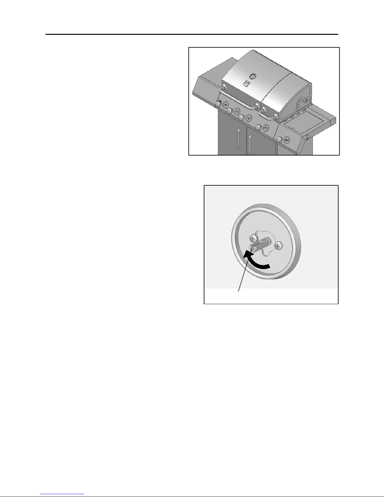
Use & Care Guide
Manual de Uso y Cuidado
English / Español
Model/Modelo: 10478
Kenmore®
Natural Gas Conversion Kit
Paquete de conversion a gas natural
P/N 10478-Manual
Sears Brands Management Corporation
Hoffman Estates, IL 60179 U.S.A.
www.kenmore.com
www.sears.com
www.kmart.com
®
Page 2
TABLE OF CONTENTS
2
Package Contents…………………………………………………….…...….………….…….…...3
Conversion Instructions………………………………………………....….………….…….….5
Use & Care……………………………………………………………………………30
Troubleshooting ………………………………………………………………………………….31
Warranty …………………………………………………………………………………………….32
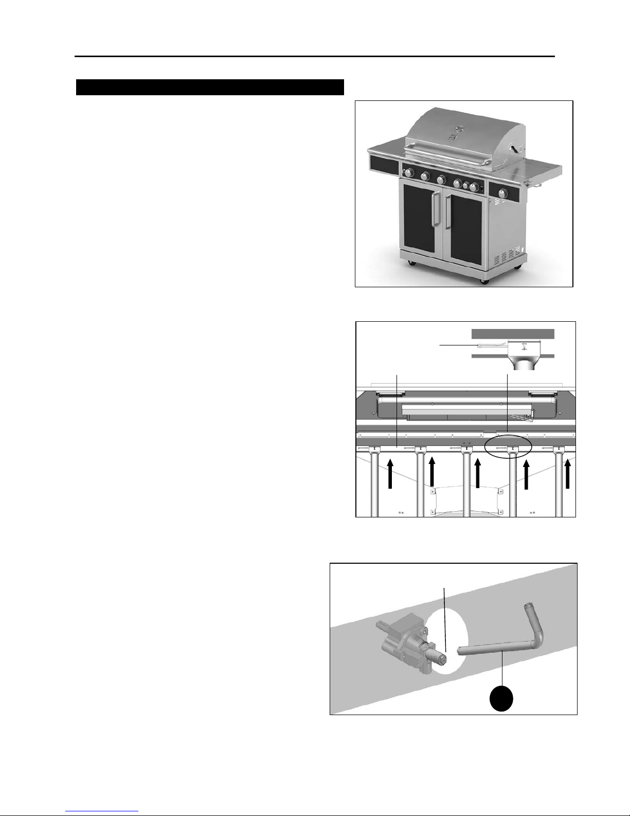
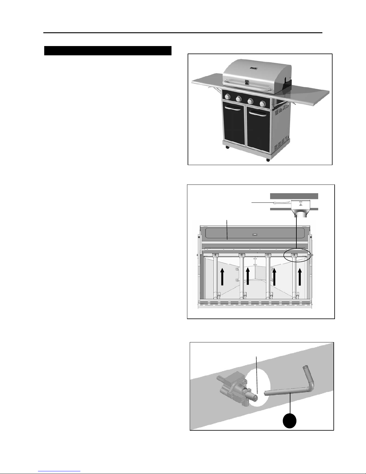
PREPARATION
Before beginning conversion, make sure all parts are present. Compare parts with package
contents list. If any part is missing or damaged, do not attempt to convert. Contact customer
service for replacement parts at 1-800-482-0131.
NOTE: Damage to grill as a result of incorrect conversion to natural gas is not covered
by the grill or the conversion kit warranty.
© 2013 KCD IP, LLC
CALIFORNIA PROPOSITION 65
1. Combustion by-products produced when using
this product contain chemicals known to the
State of California to cause cancer, birth
defects, and other reproductive harm.
2. This product contains chemicals, including lead
and lead compounds, known to the State of
California to cause cancer, birth defects or
other reproductive harm.
Wash your hands after handling this product
WARNING
Place the grill on a flat, level surface before
starting the conversion.
We strongly recommend that you hire a
professionally trained technician to install this
Natural Gas Conversion Kit. Incorrect installation
may result in explosion and serious injury.
WARNING
Page 3
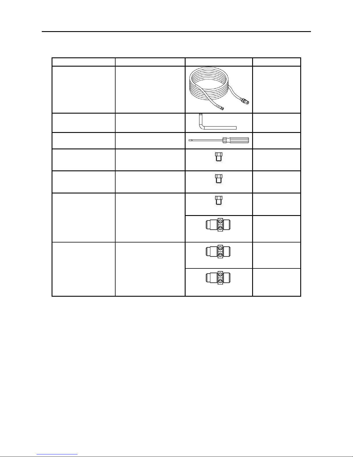
PACKAGE CONTENTS
3
Parts List
Part Description Illustration Qty. Supplied
A 10-FT Natural Gas Hose
1
B Orifice Change Tool
1
C Flathead Screwdriver
1
D Main Burner Orifice
D=1.37mm
5
E Searing Burner Orifice
D=1.44mm
1
D=1.31mm
1
F Side Burner Orifice
D=1.37 mm
1
D=1.33 mm
0
(Provided with
Gas Grill
.)
G Rear Burner Orifice
D=1.40 mm
1
Page 4
PACKAGE CONTENTS
4
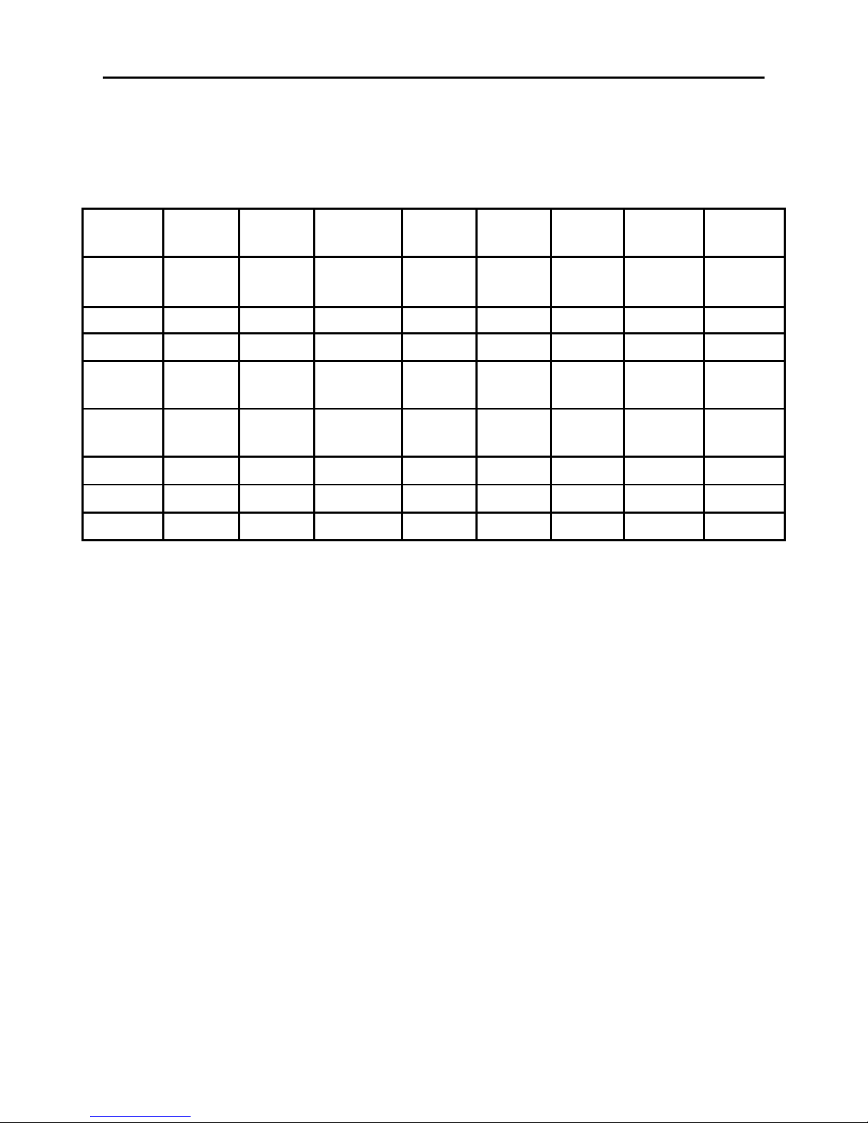
Orifices Used per Grill Model
Gas Grill
Model No.
Conversion
Kit Model No
Main Burner
D = 1.37 mm
Qty. Used
Searing Burner
D = 1.44mm
Qty. Used
Side Burner
D = 1.31mm
Qty. Used
Side Burner
D = 1.37mm
Qty. Used
Rear Burner
D = 1.33mm
Qty. Used
Rear Burner
D = 1.40mm
Qty. Used
NG KIT
Vendor Model
No.
16656
3032
OR
10478
3 1 1 N/A NA N/A L3018S-1-KIT
16136 10478 5 N/A N/A 1 N/A 1 S3218A-KIT
16137 10478 5 N/A N/A 1 N/A 1 S3218A-KIT
16156 10478 5 N/A N/A 1
1
Provided
with Gas
Grill
N/A S3218AN-KIT
16157 10478 5 N/A N/A 1
1
Provided
with Gas
Grill
N/A S3218AN-KIT
16154 10478 4 N/A N/A N/A N/A N/A 2818-2T-KIT
23682
10478
3 1 1 N/A NA N/A L3018SN-KIT
23683
10478
4 N/A 1 N/A NA N/A RB2818T-KIT
Page 5
CONVERSION INSTRUCTIONS
5
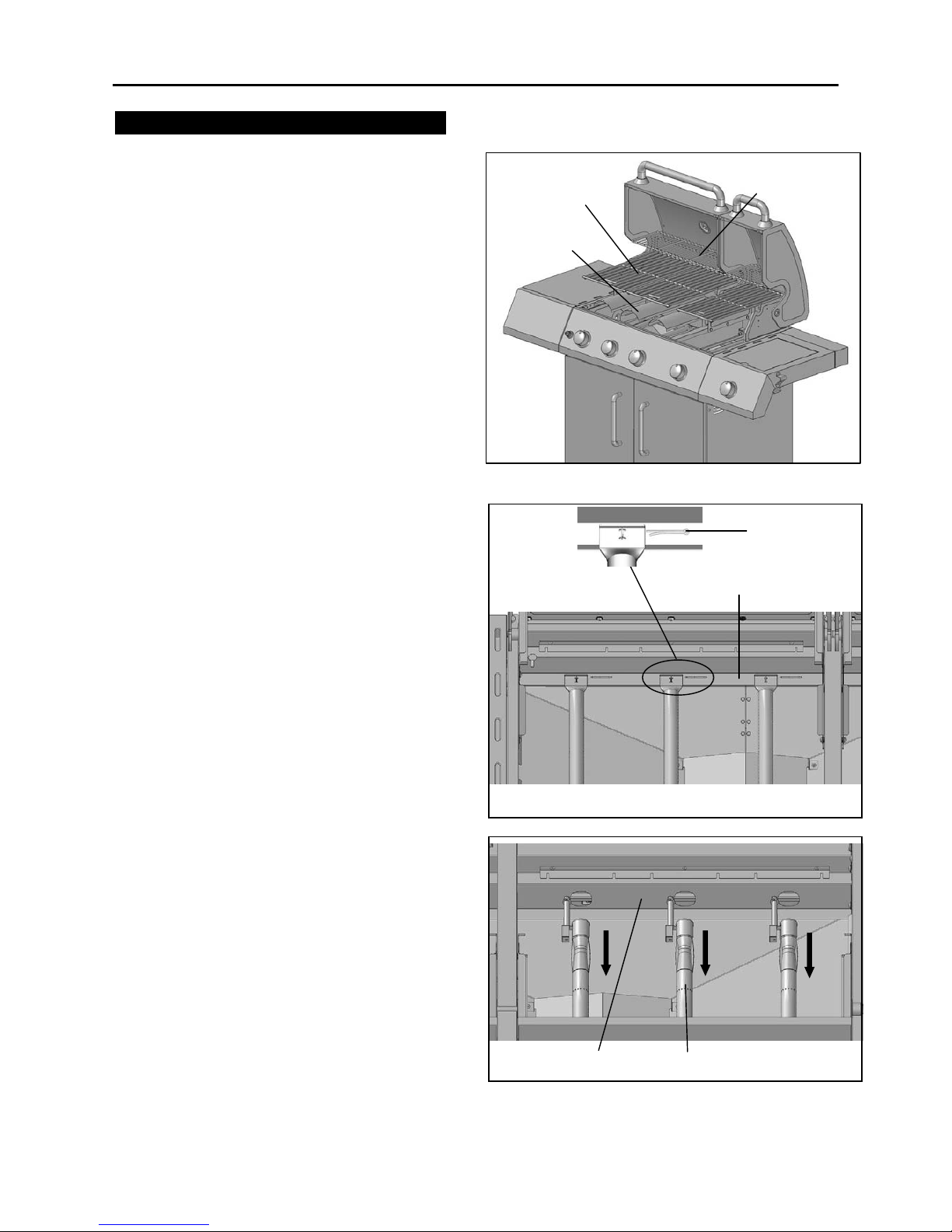
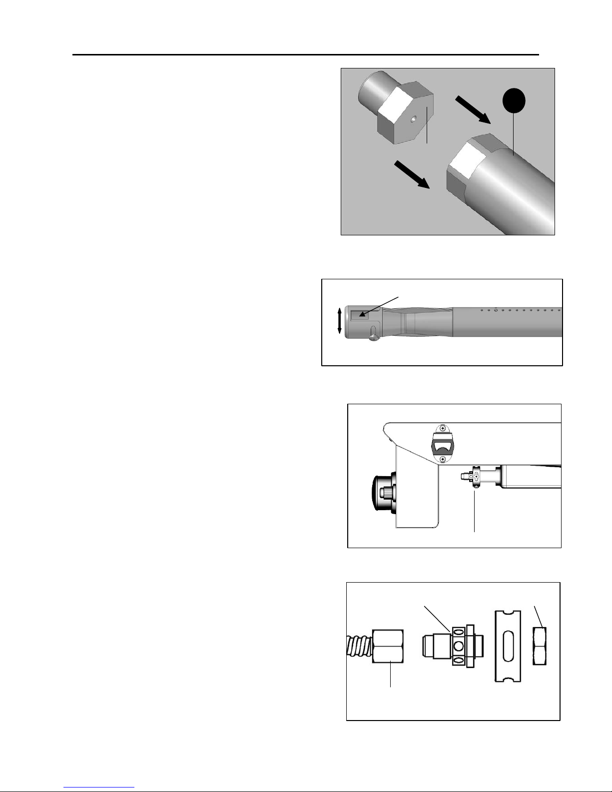
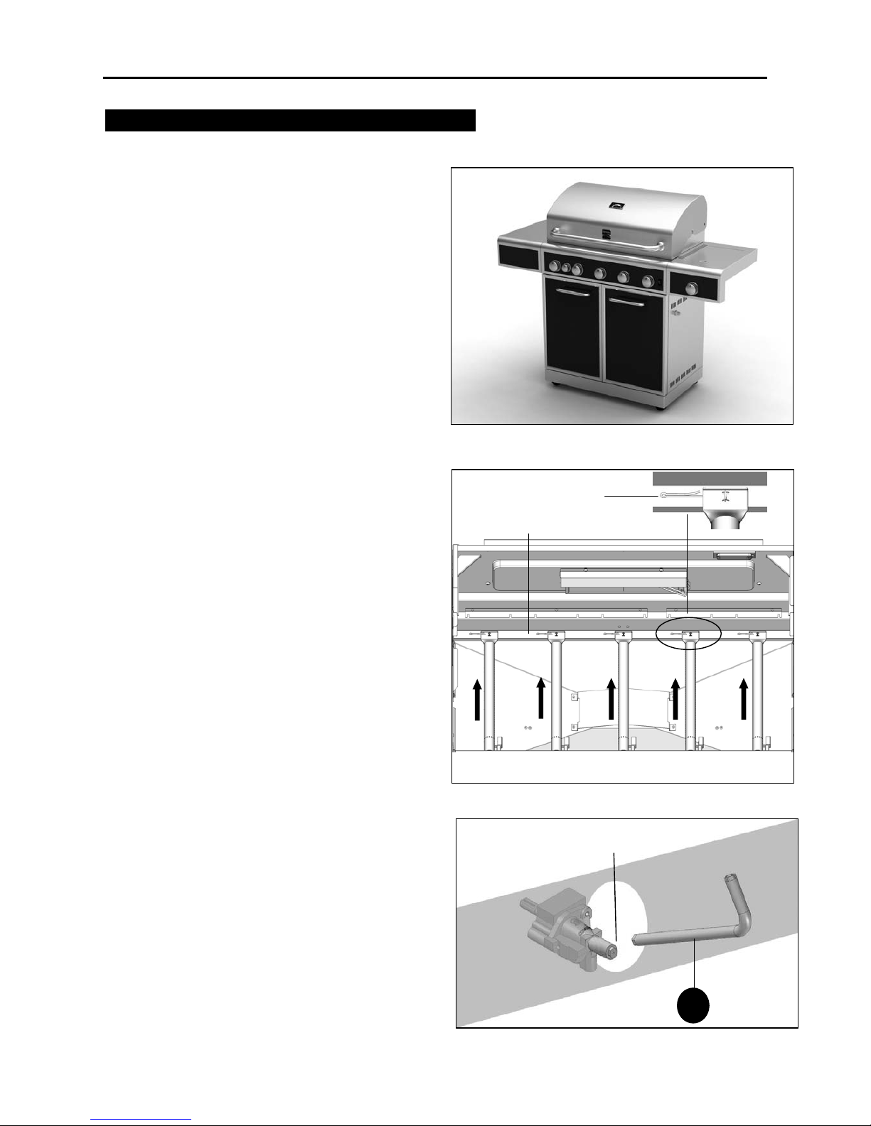
Conversion Instructions for 16656
Before starting the conversion, make sure
all control knobs are in the OFF position,
LP tank valve is closed, and tank is
disconnected from regulator and removed
from grill. Next, open all lids and remove
warming racks, cooking grids, and heat
diffusers. (Fig. 1)
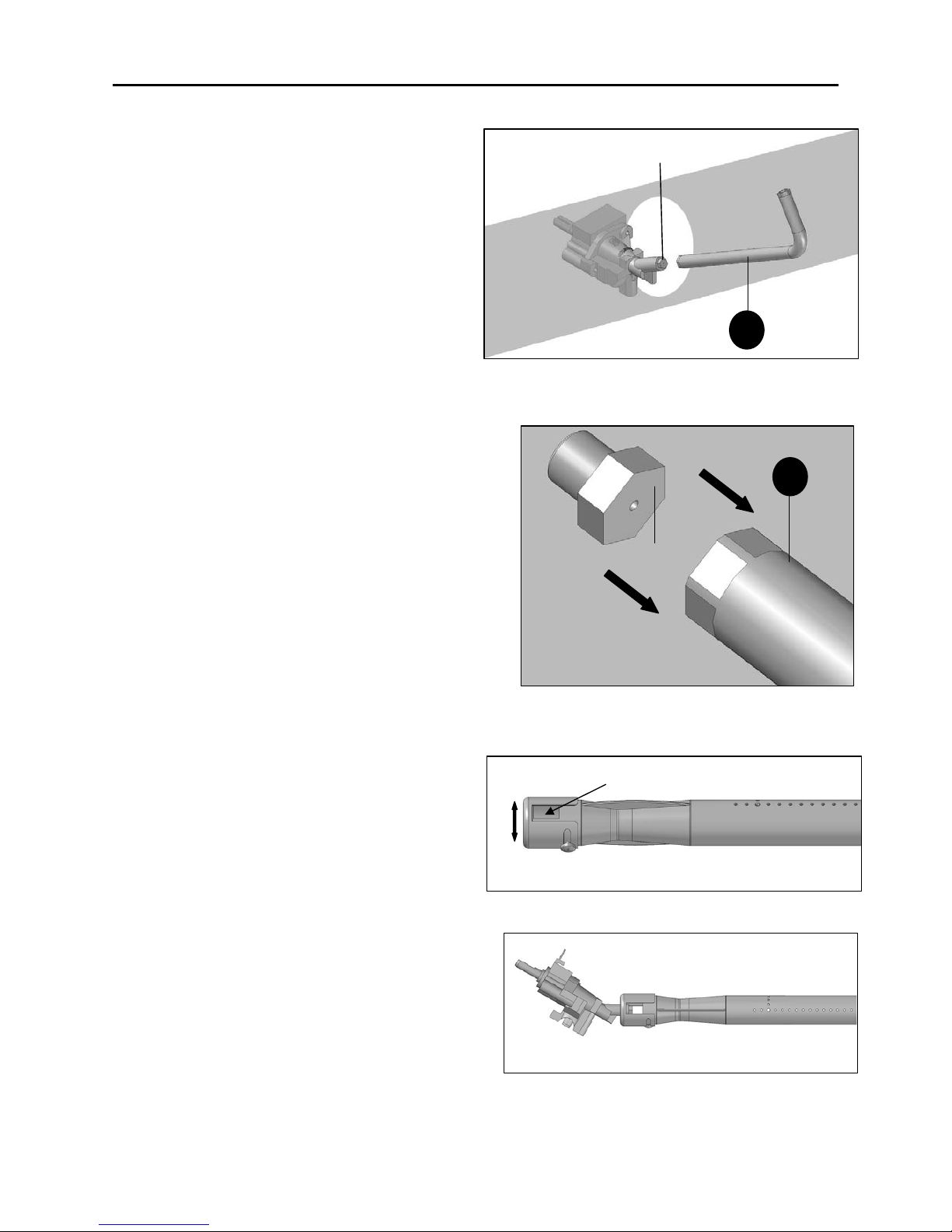
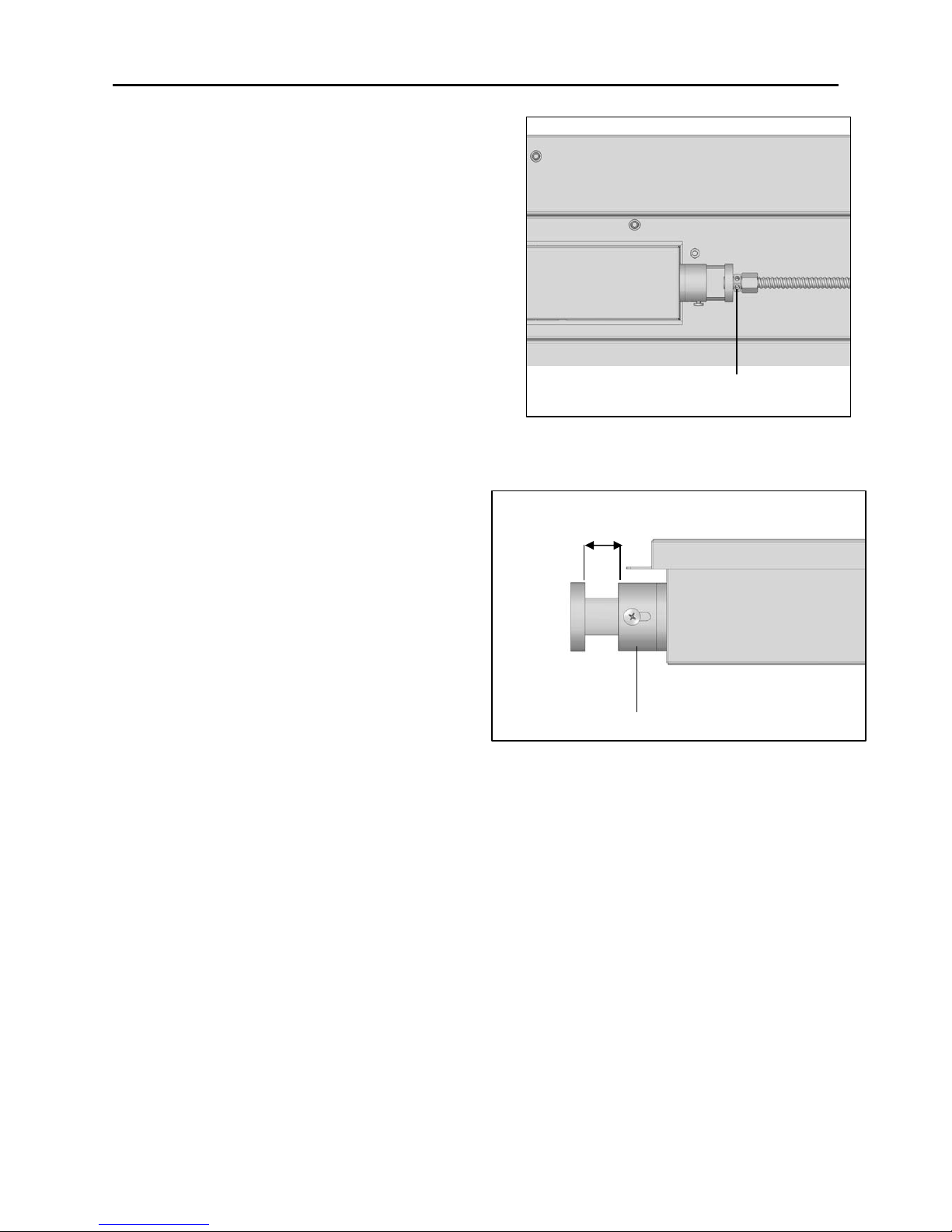
Main Burner Conversion
1. Remove the R pins at the back of main
burners to detach burners from bracket.
(Fig. 2)
2. Lift back of main burners while sliding
burners out of firebox, disengaging main
burners from valves. (Fig. 3)
Warming
rack
Heat diffusers
Fig. 1
Grids
Fig. 3
Main burner
Front of Firebox
Fig. 2
R pin
Back of Firebox
Page 6
CONVERSION INSTRUCTIONS
6
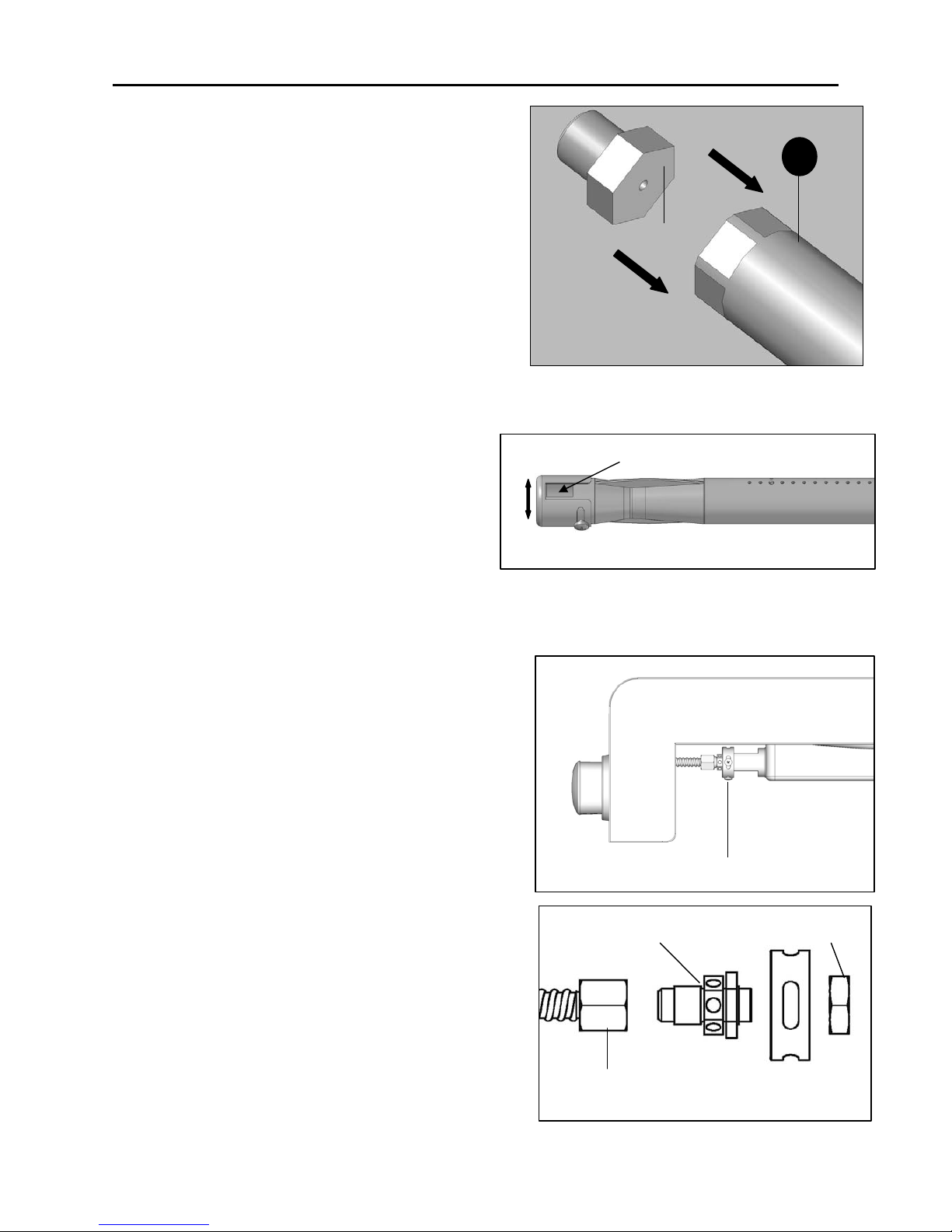
3. Insert the provided orifice removal tool (B)
into burner openings and unscrew orifices
from ends of valves. (Fig. 4)
4. Put the new orifice into the orifice
removal tool (B), and then insert the tool
into the burner opening and tighten the new
orifice into the valve.
Repeat this step for all three burners.
Make sure you are using the correct orifice,
which is marked “1.37”. (Fig. 5)
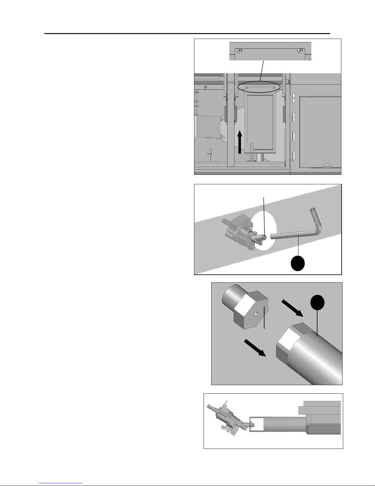
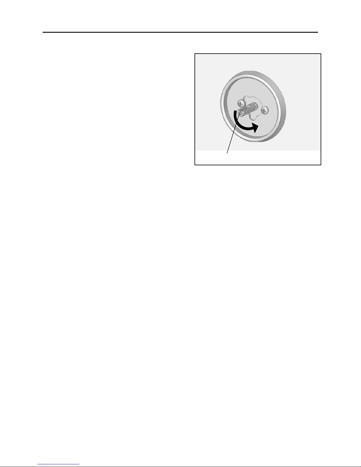
5. Rotate the air shutter opening from the
LP setting to the NG setting.
LP: 1/4" open
NG: 1/6" to 1/8" open
(Fig. 6)
6. Replace burner tube and pins. Make sure
to engage the burner valves as shown.
(Fig. 7)
Air shutter opening to adjust
Fig. 6
The main burner
Fig.7
1.37
Fig. 5
B
Orifice
Fig. 4
B
Page 7
CONVERSION INSTRUCTIONS
7
Searing Burner Conversion
1. Remove screws at the back of searing
burner to detach it from bracket. Then lift
the burner while sliding it out of firebox.
(Fig. 8)
2. Insert the provided orifice removal tool (B)
into the burner opening and unscrew orifice
from end of valve.(Fig.9)
3. Put the new orifice into the orifice
removal tool (B), and then insert the tool
into the burner opening and tighten the new
orifice to the valve.
Make sure you are using the correct orifice,
which is marked “1.44”. (Fig. 10)
4. Replace burner and screws. Make sure
to engage the tube over valve as shown.
(Fig. 11)
Fig. 8
The sear burner
Fig. 11
Orifice
Fig. 9
B
1.44
Fig. 10
B
Page 8
CONVERSION INSTRUCTIONS
8
Side Burner Conversion
1. Loosen the side burner screws to expose
the side burner valve.
Insert the tool onto the valve and unscrew orifice
from end of valve. Put the new orifice into the
orifice removal tool and tighten the new orifice
into the valve.
Make sure you are using the correct orifice,
which is marked “1.31”. (Fig. 12)
2. Engage burner tube over valve as shown.
(Fig. 13)
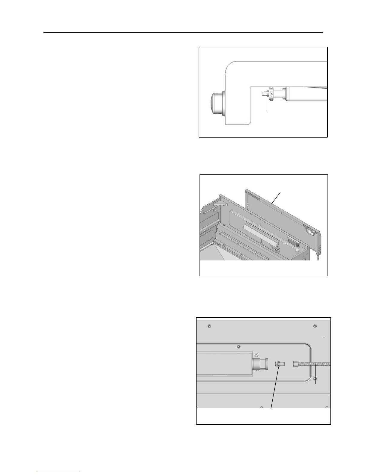
Natural Gas Hose Connection
1. Remove the LP gas hose and regulator using a wrench, and attach the natural gas hose in
it's place. (Fig. 14)
Fig. 12
The side burner
Fig. 13
Fig. 14
LP gas hose and regulator
NG Hose
Page 9
CONVERSION INSTRUCTIONS
9
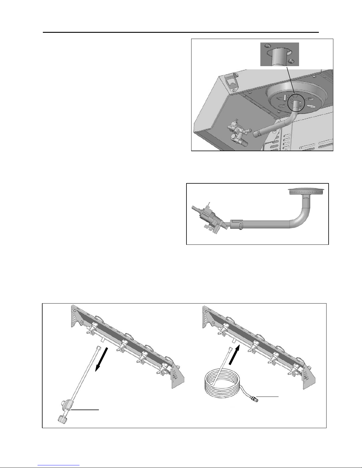
Adjust valve control screw
1. Pull all the knobs off of valve stems.
(Fig. 15)
2. Adjust the screw in each valve hole
using the flathead screwdriver (C).
Turn screw clockwise until tight.
(Fig. 16)
3. Press all the knobs back onto valve stems.
4. After all the conversions are complete, return heat diffusers to firebox, followed by the
grates and warming rack.
Fig. 15
Valve hole
Fig. 16
Page 10
CONVERSION INSTRUCTIONS
10
Conversion Instructions for 16136 / 16137
Main Burner Conversion
1. Remove the R pins at the back of main
burners to detach burners from bracket.
Lift back of main burners while sliding
burners out of firebox, disengaging main
burners from valves. (Fig. 17)
2. Insert the provided orifice removal tool (B)
into burner openings and unscrew orifices
from ends of valves. (Fig. 18)
Fig. 17
R pin
Back of Firebox
Orifice
Fig. 18
B
Page 11
CONVERSION INSTRUCTIONS
11
3. Put the new orifice into the orifice
removal tool (B), and then insert the tool
into the burner opening and tighten the new
orifice into the valve.
Repeat this step for all five burners.
Make sure you are using the correct
orifice, which is marked “1.37”. (Fig. 19)
4. Rotate the air shutter opening from the
LP setting to the NG setting.
LP: 1/4" open
NG: 1/6" to 1/8" open
(Fig. 20)
Side Burner Conversion
1. Remove 2 screws (5/32-32x3/16 in.) from
the end of the side burner valve. (Fig. 21)
2. Use a wrench to remove the orifice
between the side burner hose and the
orifice nut. (Fig. 22)
5/32-32x3/16 in. screw
Fig. 21
Hose
Orifice nut
Orifice
Fig. 22
1.37
Fig. 19
B
Air shutter opening to adjust
Fig. 20
Page 12
CONVERSION INSTRUCTIONS
12
3. Tighten the new orifice to the valve.
Make sure you are using the correct orifice,
marked “1.37”. (Fig. 23)
Rear Burner Conversion
1. Remove 5 screws (3/16-24 X 1/2 in.) at the
back of burner box to detach the rear burner
cover from the rear panel of burner box.
During this process, hold the rear burner
cover, otherwise, it will drop and may
break, possibly causing injury. (Fig. 24)
2. Use wrench to remove rear burner orifice
from the rear burner and the hose. (Fig. 25)
1.37
Fig. 23
Rear burner
cover
Fig. 24
Rear burner
Hose
Orifice
Fig. 25
Page 13
CONVERSION INSTRUCTIONS
13
3. Replace it with the NG orifice, and then tighten.
Make sure you are using the correct orifice,
marked “1.4”. (Fig. 26)
Natural Gas Hose Connection
1. Remove the LP gas hose and regulator using a wrench, and attach the natural gas
hose in it's place. (Fig. 27)
Rear burner
1.4
Fig.26
Fig. 27
LP gas hose and regulator
NG Hose
Page 14
CONVERSION INSTRUCTIONS
14
Adjust valve control screw
1. Pull all the knobs off of valve stems. Adjust
the screw in the valve hole using the flathead
screwdriver (C). Turn screws two complete
turns (720°) counterclockwise.
(Fig. 28)
2. Press all the knobs back onto valve stems.
3. After all the conversions are complete, return heat diffusers to firebox, followed by the
grates and warming rack.
Valve hole
Fig. 28
Page 15
CONVERSION INSTRUCTIONS
15
Conversion Instructions for 16156 / 16157
Note:
Before conversion, please find the
1.33mm nozzle provided with the grill
which will be used together with the
conversion kit.
Main Burner Conversion
1. Remove the R pins at the back of main
burners to detach burners from bracket.
Lift back of main burners while sliding
burners out of firebox, disengaging main
burners from valves. (Fig. 29)
2. Insert the provided orifice removal tool (B)
into burner openings and unscrew orifices
from ends of valves. (Fig. 30)
Fig. 29
R pin
Back of Firebox
Orifice
Fig. 30
B
Page 16
CONVERSION INSTRUCTIONS
16
3. Put the new orifice into the orifice
removal tool (B), and then insert the tool
into the burner opening and tighten the new
orifice into the valve.
Repeat this step for all five burners.
Make sure you are using the correct
orifice, which is marked “1.37”. (Fig. 31)
4. Rotate the air shutter opening from the
LP setting to the NG setting.
LP: 1/4" open
NG: 1/6" to 1/8" open
(Fig. 32)
Side Burner Conversion
1. Remove 2 screws (5/32-32x3/16 in.) from
the end of the side burner valve. (Fig. 33)
2. Use a wrench to remove the orifice
between the side burner hose and the
orifice nut. (Fig. 34)
5/32-32x3/16 in. screw
Fig. 33
Hose
Orifice nut
Orifice
Fig. 34
1.37
Fig. 31
B
Air shutter opening to adjust
Fig. 32
Page 17
CONVERSION INSTRUCTIONS
17
3. Tighten the new orifice to the valve.
Make sure you are using the correct orifice,
marked “1.37”. (Fig. 35)
Rear Burner Conversion
1. Remove 5 screws (3/16-24 X 1/2 in.) at the
back of burner box to detach the rear burner
cover from the rear panel of burner box.
During this process, hold the rear burner
cover, otherwise, it will drop and may
break, possibly causing injury. (Fig. 36)
2. Use wrench to remove rear burner orifice
from the rear burner and the hose. (Fig. 37)
1.37
Fig. 35
Rear burner
cover
Fig. 36
Rear burner
Hose
Orifice
Fig. 37
Page 18
CONVERSION INSTRUCTIONS
18
3. Replace it with the NG orifice, and then tighten.
Make sure you are using the correct orifice,
marked “1.33”. (Fig. 38)
Note: The orifice is not included in the 10478
kit, it is provided with the 16156/16157 grill.
4. Loosen the air shutter of the rear burner
and adjust the distance between air shutter
and rear burner. In LPG model, the air
shutter is at its rightmost position, and the
distance is about 0.67 inch; and in NG
model, the air shutter should be at its
leftmost position, and the distance is about
0.4 inch. Please use a screwdriver to adjust
the distance. After adjustment, tighten the
screw. (Fig. 39)
Rear burner
1.33
Fig. 38
rear burner
air shutter
Distance
Fig. 39
Page 19
CONVERSION INSTRUCTIONS
19
Natural Gas Hose Connection
1. Remove the LP gas hose and regulator using a wrench, and attach the natural gas
hose in it's place. (Fig. 40)
Adjust valve control screw
1. Pull all the knobs off of valve stems. Adjust
the screw in the valve hole using the flathead
screwdriver (C). Turn screws two complete
turns (720°) counterclockwise.
(Fig. 41)
2. Press all the knobs back onto valve stems.
After all the conversions are complete, return heat diffusers to firebox, followed by the grates
and warming rack.
Fig. 40
LP gas hose and regulator
NG Hose
Valve hole
Fig. 41
Page 20
CONVERSION INSTRUCTIONS
20
Conversion Instructions for 16154
Main Burner Conversion
1. Remove the R pins at the back of main
burners to detach burners from bracket.
Lift back of main burners while sliding
burners out of firebox, disengaging main
burners from valves. (Fig. 42)
2. Insert the provided orifice removal tool (B)
into burner openings and unscrew orifices
from ends of valves. (Fig. 43)
Orifice
Fig. 43
B
Fig. 42
R pin
Back of Firebox
Page 21

CONVERSION INSTRUCTIONS
21
3. Put the new orifice into the orifice
removal tool (B), and then insert the tool
into the burner opening and tighten the new
orifice into the valve.
Repeat this step for all four burners.
Make sure you are using the correct
orifice, which is marked “1.37”. (Fig. 44)
4. Rotate the air shutter opening from the
LP setting to the NG setting.
LP: 1/4" open
NG: 1/6" to 1/8" open
(Fig. 45)
Natural Gas Hose Connection
Remove the LP gas hose and regulator using a wrench, and attach the natural gas
hose in it's place. (Fig. 46)
1.37
Fig. 44
B
Air shutter opening to adjust
Fig. 45
Fig. 46
LP gas hose and regulator
NG Hose
Page 22

CONVERSION INSTRUCTIONS
22
Adjust valve control screw
1. Pull all the knobs off of valve stems. Adjust
the screw in the valve hole using the
flathead screwdriver (C). Turn screws 6
complete turns counterclockwise.
(Fig. 47)
2. Press all the knobs back onto valve stems.
3. After all the conversions are complete, return heat diffusers to firebox, followed by the
grates and warming rack.
Valve hole
Fig. 47
Page 23

CONVERSION INSTRUCTIONS
23
Conversion Instructions for 23682
Main Burner Conversion
1. Remove the R pins at the back of main
burners to detach burners from bracket.
Lift back of main burners while sliding
burners out of firebox, disengaging main
burners from valves. (Fig. 48)
2. Insert the provided orifice removal tool (B)
into burner openings and unscrew orifices
from ends of valves. (Fig. 49)
Orifice
Fig. 49
B
Fig. 48
R pin
Back of Firebox
Page 24

CONVERSION INSTRUCTIONS
24
3. Put the new orifice into the orifice removal
tool (B), and then insert the tool into the
burner opening and tighten the new orifice
into the valve.
Repeat this step for all three burners.
Make sure you are using the correct
orifice, which is marked “1.37”.
(Fig. 50)
4. Rotate the air shutter opening from the
LP setting to the NG setting.
LP: 1/4" open
NG: 1/6" to 1/8" open
(Fig. 51)
Searing Burner Conversion
1. Remove screws at the back of searing
burner to detach it from bracket. Then lift
the burner while sliding it out of firebox.
(Fig. 52)
2. Insert the provided orifice removal tool (B)
into the burner opening and unscrew orifice
from end of valve.(Fig.53)
1.37
Fig. 50
B
Air shutter opening to adjust
Fig. 51
Fig. 52
Orifice
Fig. 53
B
Page 25

CONVERSION INSTRUCTIONS
25
3. Put the new orifice into the orifice
removal tool (B), and then insert the tool
into the burner opening and tighten the new
orifice to the valve.
Make sure you are using the correct orifice,
which is marked “1.44”. (Fig. 54)
4. Replace burner and screws. Make sure
to engage the tube over valve as shown.
(Fig. 55)
Side Burner Conversion
1. Remove the side burner screws
(5/32-32x3/8 in.) to expose the side burner
valve.
Insert the tool onto the valve and unscrew
orifice from end of valve. Put the new orifice
into the orifice removal tool and tighten the
new orifice into the valve.
Make sure you are using the correct
orifice, which is marked “1.31”. (Fig. 56)
2. Engage burner tube over valve as shown.
(Fig. 57)
5/32-32x3/8 in. screw
Fig. 56
Fig. 57
The side burner
The sear burner
Fig. 55
1.44
Fig. 54
B
Page 26

CONVERSION INSTRUCTIONS
26
Natural Gas Hose Connection
1. Remove the LP gas hose and regulator using a wrench, and attach the natural gas
hose in it's place. (Fig. 58)
Adjust valve control screw
1. Pull all the knobs off of valve stems.
Adjust the screw in the valve hole
using the flathead screwdriver. Turn
screws two complete turns
counterclockwise.
(Fig. 59)
2. Press all the knobs back onto valve stems.
3. After all the conversions are complete, return heat diffusers to firebox, followed by the
grates and warming rack.
Valve hole
Fig. 59
Fig. 58
LP gas hose and regulator
NG Hose
Page 27

CONVERSION INSTRUCTIONS
27
Conversion Instructions for 23683
Main Burner Conversion
1. Remove the R pins at the back of main
burners to detach burners from bracket.
Lift back of main burners while sliding
burners out of firebox, disengaging main
burners from valves. (Fig. 60)
2. Insert the provided orifice removal tool (B)
into burner openings and unscrew orifices
from ends of valves. (Fig. 61)
Fig. 60
R pin
Back of Firebox
Orifice
Fig. 61
B
Page 28

CONVERSION INSTRUCTIONS
28
3. Put the new orifice into the orifice removal
tool (B), and then insert the tool into the
burner opening and tighten the new orifice
into the valve.
Repeat this step for all five burners.
Make sure you are using the correct
orifice, which is marked “1.37”. (Fig. 62)
4. Rotate the air shutter opening from the
LP setting to the NG setting.
LP: 1/4" open
NG: 1/6" to 1/8" open
(Fig. 63)
Side Burner Conversion
1. Loosen the side burner screws to expose
the side burner valve.
Insert the tool onto the valve and unscrew
Orifice from end of valve. Put the new
orifice into the orifice removal tool and
tighten the new orifice into the valve.
Make sure you are using the correct orifice,
which is marked “1.31”. (Fig. 64)
2. Engage burner tube over valve as shown
and tighten the loosened screws .(Fig. 65)
1.37
Fig. 62
B
Air shutter opening to adjust
Fig. 63
Fig. 64
Loosen
The side burner
Fig. 65
Page 29

CONVERSION INSTRUCTIONS
29
Natural Gas Hose Connection
1. Remove the LP gas hose and regulator using a wrench, and attach the natural gas
hose in it's place. (Fig. 66)
Adjust valve control screw
1. Pull all the knobs off of valve stems.
Adjust the screw in the valve hole
using the flathead screwdriver. Turn
screws two complete turns
counterclockwise.
(Fig. 67)
2. Press all the knobs back onto valve stems.
3. After all the conversions are complete, return heat diffusers to firebox, followed by the
grates and warming rack.
Valve hole
Fig. 67
Fig. 66
LP gas hose and regulator
NG Hose
Page 30

USE AND CARE
30
WARNING: Many areas of an outdoor gas grill generate extreme heat. We have taken
every precaution to protect you from the contact areas. However, it is impossible to
isolate all high-temperature areas. Therefore, use good judgment and caution when
grilling on this product. We suggest a covered, protected hand during operation of grill.
Do not move your grill when it is in operation or hot to the touch. Wait until your unit is
turned off and properly cooled down before moving it. Failure to follow this warning
could result in personal injury.
Do not operate the gas grill indoors or in any enclosed area. If the gas grill is not in use, the
gas must be turned off at the supply tank. If the grill is to be stored indoors, disconnect the
gas supply hose.
When checking for gas leaks, do not use an open flame. Use a soapy water solution and
apply it to the pipe joints and fittings with a brush and check for bubbles. Check flexible hoses
for cuts and wear that may affect the safe operation of the grill. Only use original equipment
replacement hoses. Use only replacement hose assemblies specified by manufacturer.
Checking Gas Leaks
Before operating your grill, after refueling, check carefully to be certain that all connections
are tight and there are no gas leaks.
1. Make 2-3 ounces of leak solution by mixing liquid dishwashing soap with water.
2. Make certain all control knobs are in the “OFF” position.
3. Brush small amounts of the leak solution on all the fittings and turn the gas on.
4. If bubbles appear, there is a leak. Proceed to step 5.
5. Turn the gas off and tighten all connections.
6. Go back to step 1 to retest the fittings.
7. If bubbles continue to appear, turn the gas off. Contact customer service.
WARNING: Never use a match or open flame for leak detection. Use of an open flame
could result in a fire, explosion and bodily harm.
IMPORTANT: When connecting or replacing any gas pipe or fittings, all joints must be
sealed with approved leak-proof sealing compound or plumber's tape.
Never store a spare tank under or near your grill.
IMPORTANT: When connecting or replacing gas pipe or fittings, all joints must be
sealed with approved leak-proof sealing compound or plumber's tape. After making
connections, check all joints for leaks using a soapy water solution and a brush.
WARNING: Never use an open flame to test for gas leaks. Use of an open flame could
result in a fire, explosion and bodily harm.
Page 31

TROUBLESHOOTING
31
Many solutions given here can make your grilling experience safer and more enjoyable.
Problem Possible Cause Corrective Action
Grill or side burner
will not light
1. The ignition system is not
properly installed.
2. Other possible causes are
described in the Use and
Care Guide.
1. Reinstall the ignition system and
make sure the sparks are
produced close to the burner
ports or close to the infrared
burner ceramic surface.
2. Please refer to the Use and Care
Guide for more details.
Burner flame is
yellow and gas
odor can be
smelled
1. The air shutter opening is
not properly set.
2. Spiders or insects block the
air shutter.
3. Gas leaks.
1. Loosen the air shutter and adjust
the opening to have blue flames.
1/16 in. to 1/8 in. opening for NG.
2. Clean blockages.
3. Check for the source of gas
leaks.
Low heat with the
knob in “HI”
position
1. Natural gas pressure is low.
2. Installed with the wrong
nozzles.
3. Burner ports are blocked.
1. This model is set for 7 in. natural
gas pressure usage. Please
check your natural gas supply
system to have correct gas
pressure. Regulator is not
needed after NG conversion.
2. Check the valves to make sure
you installed the correct NG
orifices.
(See the orifice sizes on page 3.)
3. Clear burner ports of any
obstructions.
Low heat,
natural gas
Gas pressure is significantly
affected by gas line and
length of gas line from house
gas line.
Check your gas line and make
corrections by following the chart
below.
From House to Grill
Distance Tubing Size
Up to 25 ft. 3/8 in. diameter
26 ft.-50 ft. 1/2 in. diameter
51 ft.-100 ft.
2/3 of run 3/4 in.
1/3 of run 1/2 in.
Page 32

WARRANTY
32
Kenmore Full Warranty
If this Kenmore product fails due to a defect in material or workmanship within one year from
the date of purchase, call 1-800-4-MY-HOME to arrange for a free replacement.
This warranty is void if this product is ever used for commercial or rental purposes.
This warranty gives you specific legal rights, and you may also have other rights which vary
from state to state.
Sears Brands Management Corporation
Hoffman Estates, IL 60179
Page 33

ÍNDICE
33
Contenido del paquete……………………………………………………..…….…..……...…...34
Instrucciones de conversión……………………………………………….………….…….…36
Uso y cuidado……………………………………………………………………………63
Solución de problemas………………………………………………………………………….64
Garantía …………………………………………………………………………………………….65
PREPARACIÓN
Antes de comenzar la conversión, asegúrese de tener todas las piezas. Compare las piezas
con la lista del contenido del paquete. No convierta el producto si falta alguna pieza o si éstas
están dañadas. Para obtener las piezas de repuesto, póngase en contacto con el
Departamento de Servicio al Cliente al 1-800-482-0131.
AVISO: La garantía de la parrilla o del kit de conversión no cubren el daño a la parrilla
como resultado de una conversión incorrecta a gas natural.
Coloque la parrilla sobre una superficie plana y
nivelada antes de comenzar la conversion. Le
recomendamos encarecidamente que contrate a un
profesional capacitado para que instale el kit de
conversión a gas natural. Una instalación incorrecta
puede provocar una explosión y lesiones graves.
ADVERTENCIA
PROPOSICION 65 DEL ESTADO DE CALIFORNIA
1. En el estado de California se sabe que Los
subproductos de la combustión, que se producen al us ar
este producto, contienen substancias químicas que
causan cáncer, defectos congénitos u otras lesion es al
aparato reproductor.
2. Este producto contiene substancias químicas,
incluyendo el plomo y compuestos de plomo, qu e en el
estado de Califomia se sabe que las causan cáncer,
defectos congénitos u otras lesiones al ap arato
reproductor.
Lávese las manos después de manipular este
A
DVERTENCIA
Page 34

CONTENIDO DEL PAQUETE
34
Lista de piezas
Pieza Descripción Ilustración Cantidad
suministrada
A
Manguera para gas
natural de 3,05 M
1
B
Herramienta de cambio
de orificio
1
C
Destornillador de cabeza
plana
1
D
Orificio del quemador
principal
D=1.37mm
5
E
Orificio del quemador
para asar
D=1.44mm
1
D=1.31mm
1
F
Orificio del quemador
lateral
D=1.37 mm
1
D=1.33 mm
0
(Siempre con
parrilla de gas.)
G
Orificio del quemador
posterior
D=1.40 mm
1
Page 35

CONTENIDO DEL PAQUETE
35
Orificios utilizados según el modelo de la parrilla
Parrilla
modelo No.
Kit de
conversión
de N º de
modelo
Quemador
principal
D = 1,37 mm
Cantidad
utilizada
Quemador para
asar
D = 1,44mm
Cantidad
utilizada
Quemador
lateral
D = 1,31mm
Cantidad
utilizada
Quemador
lateral
D = 1,37mm
Cantidad
utilizada
Quemador
posterior
D = 1,33mm
Cantidad
utilizada
Quemador
posterior
D = 1,40mm
Cantidad
utilizada
NG KIT
Proveedor N º
de modelo
16656
3032
OR
10478
3 1 1 N/A NA N/A L3018S-1-KIT
16136 10478 5 N/A N/A 1 N/A 1 S3218A-KIT
16137 10478 5 N/A N/A 1 N/A 1 S3218A-KIT
16156 10478 5 N/A N/A 1
1
Siempre con
parrilla de
gas
N/A S3218AN-KIT
16157 10478 5 N/A N/A 1
1
Siempre con
parrilla de
gas
N/A S3218AN-KIT
16154 10478 4 N/A N/A N/A N/A N/A 2818-2T-KIT
23682
10478
3 1 1 N/A NA N/A L3018SN-KIT
23683
10478
4 N/A 1 N/A NA N/A RB2818T-KIT
Page 36

INSTRUCCIONES DE CONVERSIÓN
36
Instrucciones de conversión para el modelo 16656
1. Antes de comenzar la conversión,
asegúrese de que todas las perillas de control
estén la posición de APAGADO, que la válvula
del tanque PL esté cerrada y que el tanque
esté desconectado del regulador y se haya
retirado de la parrilla. Luego abra todas las
tapas y retire las rejillas para calentar, las
parrillas de cocción y los difusores de calor.
(Fig. 1)
Conversión del quemador principal
1. Retire los pasadores en forma de R de
la parte posterior de los quemadores
principales para extraerlos de la abrazadera.
(Fig. 2)
2. Levante la parte posterior de los
quemadores principales mientras los desliza
hacia fuera de la cámara de combustión,
soltándolos de las válvulas. (Fig. 3)
Rejilla para
calenta
r
Difusores de
calo
r
Fig. 1
Parrillas
Fig. 3
Quemador
p
rincipal
Parte delantera de la
cámara de combustión
Fig. 2
Pasador en
forma de R
Parte posterior de la
cámara de combustión
Page 37

INSTRUCCIONES DE CONVERSIÓN
37
3. Inserte la herramienta para eliminar
orificios (B) proporcionada en las aberturas
del quemador y desatornille los orificios de los
extremos de las válvulas. (Fig. 4)
4. Coloque el nuevo orificio en la herramienta
para eliminar orificios (B), luego inserte la
herramienta en la abertura del quemador y
apriete el nuevo orificio en la válvula.
Repita este paso para los tres quemadores.
Asegúrese de que está utilizando el orificio
correcto, el cual está marcado como “1,37”.
(Fig. 5)
5. Gire la abertura del obturador de aire del
ajuste de PL al ajuste de GN.
PL: Abertura de 6,35 mm
GN: Abertura de 4,23 mm a 3,18 mm
(Fig. 6)
6. Reemplace el tubo y los pasadores del
quemador. Asegúrese de conectar las válvulas
del quemador según se muestra. (Fig. 7)
Abertura del obturador de aire para ajustar
Fig. 6
Quemador principal
Fig.7
1.37
Fig. 5
B
Orificio
Fig. 4
B
Page 38

INSTRUCCIONES DE CONVERSIÓN
38
Conversión del quemador para asar
1. Retire los tornillos de la parte posterior
del quemador para asar para retirarlo de la
abrazadera. Luego levante el quemador
mientras lo desliza hacia fuera de la cámara
de combustión. (Fig. 8)
2. Inserte la herramienta para eliminar orificios
(B) proporcionada en la abertura del quemador
y desatornille el orificio del extremo de la
válvula. (Fig. 9)
3. Coloque el nuevo orificio en la herramienta
para eliminar orificios (B) y luego insértela en la
abertura del quemador y apriete el nuevo orificio
en la válvula.
Asegúrese de que está utilizando el orificio
correcto, el cual está marcado como “1,44”.
(Fig. 10)
4. Vuelva a colocar el quemador y los tornillos.
Asegúrese de conectar el tubo sobre las válvulas
según se muestra. (Fig. 11)
Fig. 8
Quemador para asar
Fig. 11
Orificio
Fig. 9
B
1.44
Fig. 10
B
Page 39

INSTRUCCIONES DE CONVERSIÓN
39
Conversión del quemador lateral
1. Suelte los tornillos del quemador lateral
para exponer la válvula de este quemador.
Inserte la herramienta en la válvula y desatornille
el orificio del extremo de la válvula. Coloque el
nuevo orificio en la herramienta para eliminar
orificios y apriételo en la válvula.
Asegúrese de que está utilizando el orificio
correcto, el cual está marcado como “1,31”.
(Fig. 12)
2. Conecte el tubo del quemador en la válvula según se muestra.
(Fig. 13)
Conexión de la manguera para gas natural
1. Retire la manguera y el regulador de gas PL con una llave inglesa y conecte la manguera
de gas natural en su lugar. (Fig. 14)
Fig. 12
Quemador lateral
Fig. 13
Fig. 14
Manguera y regulador de gas PL
Manguera
de gas
Page 40

INSTRUCCIONES DE CONVERSIÓN
40
Ajuste el tornillo de control de la válvula
1. Jale todas las perillas para retirarlas de
los vástagos de las válvulas. (Fig. 15)
2. Ajuste el tornillo en cada orificio de válvula
con el destornillador de cabeza plana (C).
Gire el tornillo en dirección de las manecillas
del reloj hasta apretarlo. (Fig. 16)
3. Coloque a presión todas las perillas en los vástagos de las válvulas.
4. Luego de terminar las conversiones, vuelva a colocar lo difusores de calor en la cámara
de combustión, luego las parrillas y la rejilla para calentar.
Fig. 15
Orificio de la válvula
Fig. 16
Page 41

INSTRUCCIONES DE CONVERSIÓN
41
Instrucciones de conversión para el modelo 16136 / 16137
Conversión del quemador principal
1. Retire los pasadores en forma de R de la
parte posterior de los quemadores
principales para extraerlos de la
abrazadera. Levante la parte posterior
de los quemadores principales mientras
los desliza hacia fuera de la cámara de
combustión, soltándolos de las válvulas.
(Fig. 17)
2. Inserte la herramienta para eliminar
orificios (B) proporcionada en las aberturas
del quemador y desatornille los orificios de
los extremos de las válvulas. (Fig. 18)
Fig. 17
pasador en
forma de R
Parte posterior de la
cámara de combustión
orificios
Fig. 18
B
Page 42

INSTRUCCIONES DE CONVERSIÓN
42
3. Coloque el nuevo orificio en la herramienta
para eliminar orificios (B), luego inserte la
herramienta en la abertura del quemador y
apriete el nuevo orificio en la válvula.
Repita este paso para los cinco quemadores.
Asegúrese de que está utilizando el
orificio correcto, el cual está marcado
como “1,37”. (Fig. 19)
4. Gire la abertura del obturador de aire del
ajuste de PL al ajuste de GN.
PL: Abertura de 6,35 mm
GN: Abertura de 4,23 mm a 3,18 mm
(Fig. 20)
Conversión del quemador lateral
1. Retire 2 tornillos (5/32-32x3/16”) del
extremo de la válvula del quemador lateral.
(Fig. 21)
2. Use una llave inglesa para retirar el
orificio que hay entre la manguera del
quemador lateral y la tuerca del orificio.
(Fig. 22)
Tornillo de 5/32-32x3/16”
Fig. 21
Manguera
Tuerca del
orificio
Orificio
Fig. 22
1.37
Fig. 19
B
Abertura del obturador de aire para ajustar
Fig. 20
Page 43

INSTRUCCIONES DE CONVERSIÓN
43
3. Apriete el nuevo orificio en la válvula.
Asegúrese de que está utilizando el orificio
correcto, marcado como “1,37”. (Fig. 23)
Conversión del quemador posterior
1. Retire 5 tornillos (3/16-24 X 1/2") de la parte
posterior de la caja del quemador para extraer
la cubierta del quemador posterior del panel o
la caja del quemador posterior.
Sostenga la cubierta del quemador
posterior durante este proceso, de lo
contrario, se caerá y puede romperse,
pudiendo producir lesiones. (Fig. 24)
2. Use la llave inglesa para retirar el orificio del
quemador posterior y la manguera. (Fig. 25)
1.37
Fig. 23
Cubierta del
quemador
posterior
Fig. 24
Quemador
posterior
Manguera
Orificio
Fig. 25
Page 44

INSTRUCCIONES DE CONVERSIÓN
44
3. Reemplácelo con el orificio para gas natural y
luego apriete.
Asegúrese de que está utilizando el orificio
correcto, marcado como “1,4”. (Fig. 26)
Conexión de la manguera para gas natural
1. Retire la manguera y el regulador de gas PL con una llave inglesa y conecte la
manguera de gas natural en su lugar. (Fig. 27)
Rear burner
1.4
Fig.26
Fig. 27
Manguera y regulador de gas PL
Manguera de
gas natural
Page 45

INSTRUCCIONES DE CONVERSIÓN
45
Ajuste el tornillo de control de la válvula
1. Jale todas las perillas para retirarlas de los
vástagos de las válvulas. Ajuste el tornillo del
orificio de la válvula con el destornillador de
cabeza plana (C). Tornillos de dos vueltas
completas (720 °) hacia la izquierda. (Fig. 28)
2. Coloque a presión todas las perillas en los vástagos de las válvulas.
3. Luego de terminar las conversiones, vuelva a colocar lo difusores de calor en la cámara
de combustión, luego las parrillas y la rejilla para calentar.
Orificio de la válvula
Fig. 28
Page 46

INSTRUCCIONES DE CONVERSIÓN
46
Instrucciones de conversión para el modelo 16156 / 16157
Nota:
Antes de la conversión, por favor,
encontrar la boquilla 1.33mm siempre con
la parrilla que se utilizará junto con el kit
de conversión.
Conversión del quemador principal
1. Retire los pasadores en forma de R de
la parte posterior de los quemadores
principales para extraerlos de la
abrazadera. Levante la parte posterior
de los quemadores principales mientras
los desliza hacia fuera de la cámara de
combustión, soltándolos de las válvulas.
(Fig. 29)
2. Inserte la herramienta para eliminar
orificios (B) proporcionada en las aberturas
del quemador y desatornille los orificios de
los extremos de las válvulas. (Fig. 30)
Fig. 29
pasador en
forma de R
Parte posterior de la
cámara de combustión
orificios
Fig. 30
B
Page 47

INSTRUCCIONES DE CONVERSIÓN
47
3. Coloque el nuevo orificio en la herramienta
para eliminar orificios (B), luego inserte la
herramienta en la abertura del quemador y
apriete el nuevo orificio en la válvula.
Repita este paso para los cinco quemadores.
Asegúrese de que está utilizando el
orificio correcto, el cual está marcado
como “1,37”. (Fig. 31)
4. Gire la abertura del obturador de aire del
ajuste de PL al ajuste de GN.
PL: Abertura de 6,35 mm
GN: Abertura de 4,23 mm a 3,18 mm
(Fig. 32)
Conversión del quemador lateral
1. Retire 2 tornillos (5/32-32x3/16”) del
extremo de la válvula del quemador lateral.
(Fig. 33)
Tornillo de 5/32-32x3/16”
Fig. 33
1.37
Fig. 31
B
Abertura del obturador de aire para ajustar
Fig. 32
Page 48

INSTRUCCIONES DE CONVERSIÓN
48
2. Use una llave inglesa para retirar el
orificio que hay entre la manguera del
quemador lateral y la tuerca del orificio.
(Fig. 34)
3. Apriete el nuevo orificio en la válvula.
Asegúrese de que está utilizando el orificio
correcto, marcado como “1,37”. (Fig. 35)
Conversión del quemador posterior
1. Retire 5 tornillos (3/16-24 X 1/2") de la parte
posterior de la caja del quemador para extraer
la cubierta del quemador posterior del panel o
la caja del quemador posterior.
Sostenga la cubierta del quemador
posterior durante este proceso, de lo
contrario, se caerá y puede romperse,
pudiendo producir lesiones. (Fig. 36)
Manguera
Tuerca del
orificio
Orificio
Fig. 34
Cubierta del
quemador
posterior
Fig. 36
1.37
Fig. 35
Page 49

INSTRUCCIONES DE CONVERSIÓN
49
2. Use la llave inglesa para retirar el orificio del
quemador posterior y la manguera. (Fig. 37)
3. Reemplácelo con el orificio para gas natural y
luego apriete.
Asegúrese de que está utilizando el orificio
correcto, marcado como “1,33”. (Fig. 38)
4. Afloje el obturador de aire del quemador
posterior y ajuste la distancia entre el
obturador y el quemador posterior. En el
modelo a gas PL, el obturador de aire se
encuentra en el extremo derecho y la
distancia es de aproximadamente 1,70 cm.
En el modelo a gas natural, el obturador de
aire debe estar en el extremo izquierdo y la
distancia debe ser de unos 1,02 cm. Ajuste
la distancia con una herramienta o con la
mano protegida por un guante. Después de
ajustar la distancia, apriete el tornillo.
(Fig. 39)
Quemador
posterior
Manguera
Orificio
Fig. 37
Quemador
posterior
1.33
Fig. 38
Quemador
posterior
obturador de aire
Distancia
Fig. 39
Page 50

INSTRUCCIONES DE CONVERSIÓN
50
Conexión de la manguera para gas natural
1. Retire la manguera y el regulador de gas PL con una llave inglesa y conecte la
manguera de gas natural en su lugar. (Fig. 40)
Fig. 40
Manguera y regulador de gas PL
Manguera de
gas natural
Page 51

INSTRUCCIONES DE CONVERSIÓN
51
Ajuste el tornillo de control de la válvula
1. Jale todas las perillas para retirarlas de los
vástagos de las válvulas. Ajuste el tornillo del
orificio de la válvula con el destornillador de
cabeza plana (C). Tornillos de dos vueltas
completas (720 °) hacia la izquierda. (Fig. 41)
2. Coloque a presión todas las perillas en los vástagos de las válvulas.
3. Luego de terminar las conversiones, vuelva a colocar lo difusores de calor en la cámara
de combustión, luego las parrillas y la rejilla para calentar.
Orificio de la válvula
Fig. 41
Page 52

INSTRUCCIONES DE CONVERSIÓN
52
Instrucciones de conversión para el modelo 16154
Conversión del quemador principal
1. Retire los pasadores en forma de R de la
parte posterior de los quemadores
principales para extraerlos de la
abrazadera. Levante la parte posterior
de los quemadores principales mientras
los desliza hacia fuera de la cámara de
combustión, soltándolos de las válvulas.
(Fig. 42)
Fig. 42
Pasador en
forma de R
Parte posterior
de la cámara de
Page 53

INSTRUCCIONES DE CONVERSIÓN
53
2. Inserte la herramienta para eliminar orificios
(B) proporcionada en las aberturas del
quemador y desatornille los orificios de los
extremos de las válvulas. (Fig. 43)
3. Coloque el nuevo orificio en la herramienta
para eliminar orificios (B), luego inserte la
herramienta en la abertura del quemador y
apriete el nuevo orificio en la válvula. Repita
este paso para los cuatro quemadores.
Asegúrese de que está utilizando el
orificio correcto, el cual está marcado
como “1,37”. (Fig. 44)
4. Gire la abertura del obturador de aire del
ajuste de PL al ajuste de GN.
PL: Abertura de 6,35 mm
GN: Abertura de 4,23 mm a 3,18 mm
(Fig. 45)
Orificios
Fig. 43
B
1.37
Fig. 44
B
Abertura del obturador de aire para ajustar
Fig. 45
Page 54

INSTRUCCIONES DE CONVERSIÓN
54
Conversión del quemador lateral
Retire la manguera y el regulador de gas PL con una llave inglesa y conecte la manguera de
gas natural en su lugar. (Fig. 46)
Fig. 46
Manguera y regulador de gas PL
Manguera de
gas natural
Page 55

INSTRUCCIONES DE CONVERSIÓN
55
Ajuste el tornillo de control de la válvula
1. Jale todas las perillas para retirarlas de los
vástagos de las válvulas. Ajuste el tornillo del
orificio de la válvula con el destornillador de
cabeza plana (C). Tornillos de seis vueltas
completas hacia la izquierda. (Fig. 47)
2. Coloque a presión todas las perillas en los vástagos de las válvulas.
3. A Luego de terminar las conversiones, vuelva a colocar lo difusores de calor en la cámara
de combustión, luego las parrillas y la rejilla para calentar.
Orificio de la válvula
Fig. 47
Page 56

INSTRUCCIONES DE CONVERSIÓN
56
Instrucciones de conversión para el modelo 23682
Conversión del quemador principal
1. Retire los pasadores en forma de R de
la parte posterior de los quemadores
principales para extraerlos de la
abrazadera. (Fig. 48)
2. Inserte la herramienta para eliminar
orificios (B) proporcionada en las
aberturas del quemador y desatornille
los orificios de los extremos de las
válvulas. (Fig. 49)
Orificio
Fig. 49
B
Fig. 48
Pasador en forma de R
Parte posterior
de la cámara de
Page 57

INSTRUCCIONES DE CONVERSIÓN
57
3. Coloque el nuevo orificio en la herramienta
para eliminar orificios (B), luego inserte la
herramienta en la abertura del quemador y
apriete el nuevo orificio en la válvula.
Repita este paso para los tres quemadores.
Asegúrese de que está utilizando el
orificio correcto, el cual está marcado
como “1,37”. (Fig. 50)
4. Gire la abertura del obturador de aire del
ajuste de PL al ajuste de GN.
PL: Abertura de 6,35 mm
GN: Abertura de 4,23 mm a 3,18 mm
(Fig. 51)
Conversión del quemador para asar
1. Retire los tornillos de la parte posterior
del quemador para asar para retirarlo de la
abrazadera. Luego levante el quemador
mientras lo desliza hacia fuera de la cámara
de combustión. (Fig. 52)
2. Inserte la herramienta para eliminar orificios
(B) proporcionada en la abertura del
quemador y desatornille el orificio del
extremo de la válvula. (Fig.53)
1.37
Fig. 50
B
Fig. 52
Orificio
Fig. 53
B
Abertura del obturador de aire para ajustar
Fig. 51
Page 58

INSTRUCCIONES DE CONVERSIÓN
58
3. Coloque el nuevo orificio en la herramienta
para eliminar orificios (B) y luego insértela en la
abertura del quemador y apriete el nuevo
orificio en la válvula.
Asegúrese de que está utilizando el orificio
correcto, el cual está marcado como “1,44”.
(Fig. 54)
4. Vuelva a colocar el quemador y los tornillos.
Asegúrese de conectar el tubo sobre las
válvulas según se muestra. (Fig. 55)
Conversión del quemador lateral
1. Suelte los tornillos del quemador lateral
para exponer la válvula de este quemador.
Inserte la herramienta en la válvula y
desatornille el orificio del extremo de la
válvula. Coloque el nuevo orificio en la
herramienta para eliminar
orificios y apriételo en la válvula.
Asegúrese de que está utilizando el
orificio correcto, el cual está marcado
como “1,31”. (Fig. 56)
2. Conecte el tubo del quemador en la
válvula según se muestra. (Fig. 57)
5/32-32x3/8 in. screw
Fig. 56
Fig. 57
Quemador lateral
Quemador para asar
Fig. 55
1.44
Fig. 54
B
Page 59

INSTRUCCIONES DE CONVERSIÓN
59
Conexión de la manguera para gas natural
1. Retire la manguera y el regulador de gas PL con una llave inglesa y conecte la
manguera de gas natural en su lugar. (Fig. 58)
Ajuste el tornillo de control de la válvula
1. ale todas las perillas para retirarlas
de los vástagos de las válvulas.
Ajuste el tornillo del orificio de la
válvula con el destornillador de
cabeza plana (C). Tornillos de seis
vueltas completas hacia la
izquierda.
(Fig. 59)
2. Coloque a presión todas las perillas en los vástagos de las válvulas.
3. A Luego de terminar las conversiones, vuelva a colocar lo difusores de calor en la cámara
de combustión, luego las parrillas y la rejilla para calentar.
Orificio de la válvula
Fig. 59
Fig. 58
Manguera y regulador de gas PL
Manguera
de gas
Page 60

INSTRUCCIONES DE CONVERSIÓN
60
Instrucciones de conversión para el modelo 23683
Conversión del quemador principal
1. Retire los pasadores en forma de R de
la parte posterior de los quemadores
principales para extraerlos de la
abrazadera. Levante la parte posterior
de los quemadores principales mientras
los desliza hacia fuera de la cámara de
combustión, soltándolos de las válvulas.
(Fig. 60)
2. Inserte la herramienta para eliminar
orificios (B) proporcionada en las
aberturas del quemador y desatornille
los orificios de los extremos de las
válvulas. (Fig. 61)
Fig. 60
Pasador en
forma de R
Parte posterior de la
cámara de combustión
Orificios
Fig. 61
B
Page 61

INSTRUCCIONES DE CONVERSIÓN
61
3. Coloque el nuevo orificio en la herramienta
para eliminar orificios (B), luego inserte la
herramienta en la abertura del quemador y
apriete el nuevo orificio en la válvula.
Repita este paso para los cuatro
quemadores.
Asegúrese de que está utilizando el
orificio correcto, el cual está marcado
como “1,37”. (Fig. 62)
4. Gire la abertura del obturador de aire del
ajuste de PL al ajuste de GN.
PL: Abertura de 6,35 mm
GN: Abertura de 4,23 mm a 3,18 mm
(Fig. 63)
Conversión del quemador lateral
1. Suelte los tornillos del quemador lateral
para exponer la válvula de este quemador.
Inserte la herramienta en la válvula y
desatornille el orificio del extremo de la
válvula. Coloque el nuevo orificio en la
herramienta para eliminar orificios y
apriételo en la válvula.
Asegúrese de que está utilizando el
orificio correcto, el cual está marcado
como “1,31”. (Fig. 64)
2. Conecte el tubo del quemador en la
válvula según se muestra. (Fig. 65)
1.37
Fig. 62
B
Fig. 64
Loosen
Quemador lateral
Fig. 65
Abertura del obturador de aire para ajustar
Fig. 63
Page 62

INSTRUCCIONES DE CONVERSIÓN
62
Conversión del quemador lateral
1. Retire la manguera y el regulador de gas PL con una llave inglesa y conecte la
manguera de gas natural en su lugar. (Fig. 66)
Ajuste el tornillo de control de la válvula
1. Jale todas las perillas para retirarlas
de los vástagos de las válvulas.
Ajuste el tornillo del orificio de la
válvula con el destornillador de
cabeza plana (C). Tornillos de seis
vueltas completas hacia la izquierda.
(Fig. 67)
2. Coloque a presión todas las perillas en los vástagos de las válvulas.
3. A Luego de terminar las conversiones, vuelva a colocar lo difusores de calor en la cámara
de combustión, luego las parrillas y la rejilla para calentar.
Orificio de la
válvula
Fig. 67
Fig. 66
Manguera y regulador de gas PL
Manguera de
gas natural
Page 63

USO Y CUIDADO
63
ADVERTENCIA: Muchas áreas de una parrilla a gas para exteriores generan calor
extremo. Hemos tomado todas las precauciones a fin de protegerlo de las áreas de
contacto. Sin embargo, es imposible aislar todas las áreas de alta temperatura. Por lo
tanto, juzgue correctamente y tenga precaución al utilizar la parrilla de este producto.
Sugerimos que se cubra y proteja las manos cuando opere la parrilla. No mueva la
parrilla mientras está en uso o caliente al tacto. Espere a que la unidad se apague y se
enfríe antes de moverla. El incumplimiento de esta advertencia podría provocar
lesiones personales.
No opere la parrilla a gas en interiores ni en ningún área cerrada. Si la parrilla a gas no está
en uso, se debe cerrar el gas desde el tanque de suministro. Si la parrilla a gas se
almacenará en interiores, la manguera de suministro del gas.
Cuando verifique si hay fugas de gas, no use una llama directa. Use una solución de agua
jabonosa y aplíquela en las conexiones y uniones de la tubería con un cepillo; verifique si
hace burbujas. Compruebe que no haya cortes y desgaste en las mangueras flexibles que
puedan afectar el funcionamiento seguro de la parrilla. Use sólo mangueras de reemplazo
del equipo original. Use sólo los ensambles de la manguera de repuesto especificados por el
fabricante.
Búsqueda de fugas de gas
Antes de operar la parrilla y después de volver a colocar combustible, verifique
cuidadosamente para asegurarse de que todas las conexiones están apretadas y que no
haya fugas de gas.
1. Prepare 59,15 ml a 88,72 ml de solución para fugas mezclando detergente líquido para
platos con agua.
2. Asegúrese de que todas las perillas de control estén en la posición de “APAGADO”.
3. Coloque pequeñas cantidades de solución para fugas con el cepillo en todas las
conexiones y abra el paso de gas.
4. Si se forman burbujas, hay una fuga. Continúe con el paso 5.
5. Cierre el paso de gas y apriete todas las conexiones.
6. Vuelva al paso 1 para volver a verificar las conexiones.
7. Si se siguen formando burbujas, cierre el paso de gas. Póngase en contacto con Servicio
al Cliente.
ADVERTENCIA: No use nunca un fósforo o una llama directa para detectar fugas. El
uso de una llama directa puede ocasionar un incendio, una explosión y lesiones
corporales.
IMPORTANTE: Cuando conecte o reemplace cualquier conexión o tubería de gas,
todas las uniones deben estar selladas con compuesto sellador a prueba de fugas o
cinta de plomero aprobada.
Nunca guarde un tanque de repuesto debajo o cerca de la parrilla.
IMPORTANTE: Cuando conecte o reemplace las conexiones o tuberías de gas, todas
las uniones deben estar selladas con compuesto sellador a prueba de fugas o cinta de
plomero aprobada. Una vez realizadas las conexiones, compruebe que no haya fugas
en las uniones con una solución de agua jabonosa y un cepillo.
ADVERTENCIA: No use nunca una llama directa para detectar fugas de gas. El uso de
una llama directa puede ocasionar un incendio, una explosión y lesiones corporales.
Page 64

SOLUCIÓN DE PROBLEMAS
64
Muchas de las soluciones ofrecidas aquí le permitirán usar la parrilla de manera más segura
y agradable.
Problema Causa posible Acción correctiva
La parrilla o el
quemador lateral no
se encienden
1. El sistema de encendido no se
instaló correctamente.
2. Se describen otras causas
posibles en la Guía de uso y
cuidado.
1. Vuelva a instalar el sistema de encendido
y asegúrese de que las chispas se
produzcan cerca de los puertos de los
quemadores o cerca de la superficie
cerámica de los quemadores infrarrojos.
2. Consulte la Guía de uso y cuidado para
obtener más detalles.
La llama del
quemador es amarilla
y se percibe olor a
gas
1. La abertura del obturador de
aire no está bien ajustada.
2. Arañas o insectos bloquean el
obturador de aire.
3. Hay fugas de gas.
1. Afloje el obturador de aire y ajuste la
abertura hasta obtener llamas azules.
Abertura de 1,59 mm a 3,18 mm para GN.
2. Despeje las obstrucciones.
3. Busque el origen de la fuga de gas.
La parrilla genera
poco calor con la
perilla en la posición
“ALTO”
1.La presión de gas natural está
baja.
2. Se instalaron las boquillas
incorrectas.
3. Los orificios de los quemadores
están bloqueados.
1. Este modelo está configurado para un
uso con presión de gas natural de 17,78
cm. Verifique su sistema de suministro
de gas natural para determinar si tiene
una presión de gas correcta. No se
necesita el regulador luego de la
conversión a gas natural.
2. Revise las válvulas para asegurarse de
haber instalado los orificios de GN
correctos. (Consulte los tamaños de los
orificios en la página 35).
3. Limpie cualquier obstrucción de los
orificios del quemador.
Se produce poco
calor, gas natural
La presión del gas se ve
considerablemente afectada por
la línea de gas y el largo de la
línea de gas proveniente de la
casa.
Verifique la línea de gas y realice las
correcciones necesarias según la siguiente
tabla.
Desde la casa hasta la parrilla
Distancia Tamaño de las
tuberías
Hasta 7,62 m 3/8” de diám etro
7,92 m a
15,24 m
1/2” de diámetro
15,54 m a
30,48 m
16,93 mm a 19,05 mm
8,47 mm a 12,70 mm
Page 65

GARANTÍA
65
Garantía total Kenmore
Si este producto falla debido a defectos en los materiales o la mano de obra en un período de
un año a partir de la fecha de compra, llame al 1-800-4-MY-HOME para coordinar un
reemplazo gratuito.
Esta garantía queda nula si este producto se usa para propósitos comerciales o de alquiler.
Esta garantía le otorga derechos legales específicos, pero podría tener también otros
derechos que varían según el estado.
Sears Brands Management Corporation
Hoffman Estates, IL 60179
Page 66

66
○
美
 Loading...