

Page 1

1931350US
0520
Operation instructions • english
WELDFORCE
KPS 3500
Page 2

2 – KEMPPI WELDFORCE KPS3500 / 0520
© KEMPPI OY
CONTENTS
1. PREFACE ...................................................................................................................... 3
1.1. INTRODUCTION ......................................................................................................... 3
1.2. PRODUCT INTRODUCTION ...................................................................................... 3
1.2.1. OPERATION CONTROL AND CONNECTORS ............................................. 3
1.3. ACCESSORIES ........................................................................................................... 4
1.3.1. REMOTE CONTROL DEVICES ..................................................................... 4
1.3.2. CABLES ......................................................................................................... 4
1.4. OPERATION SAFETY ................................................................................................. 5
2. INSTALLATION .............................................................................................................. 7
2.1. SITING THE MACHINE ............................................................................................... 7
2.2. CONNECTION TO THE MAINS SUPPLY ................................................................... 7
2.3. WELDING AND EARTH CABLES ............................................................................... 8
3. OPERATION CONTROL SWITCHES AND POTENTIOMETERS AND THEIR USE .... 8
3.1. MAIN SWITCH I/O ....................................................................................................... 8
3.2. PILOT LAMPS ............................................................................................................. 8
3.3. OPERATION OF COOLING FAN ................................................................................ 9
4. MANUAL METAL ARC WELDING ................................................................................ 9
5. MAINTENANCE ............................................................................................................. 9
5.1. CABLES ...................................................................................................................... 9
5.2. POWER SOURCE....................................................................................................... 9
5.3. REGULAR MAINTENANCE ........................................................................................ 9
6. OPERATION DISTURBANCES ................................................................................... 10
6.1. OPERATION OF THE OVERLOAD PROTECTION .................................................. 10
6.2. CONTROL FUSES .................................................................................................... 10
6.3. UNDER- AND OVERVOLTAGES IN THE MAINS SUPPLY ...................................... 10
6.4. LOSS OF A PHASE IN THE MAINS SUPPLY ........................................................... 10
7. ORDERING NUMBERS ................................................................................................11
8. TECHNICAL DATA ...................................................................................................... 12
Page 3

KEMPPI WELDFORCE KPS3500 / 0520 – 3
© KEMPPI OY
H12
H11
S11
X12
X11
01
F11
X13
X14
X15
KPS
1. PREFACE
1.1. INTRODUCTION
Congratulations on having purchased this product. Properly installed Kemppi products should
prove to be productive machines requiring maintenance at only regular intervals. This manual is
arranged to give you a good understanding of the equipment and its safe operation. It also contains
maintenance information and technical specifications. Read this manual from front to back before
installing, operating or maintaining the equipment for the first time. For further information on
Kemppi products please contact us or your nearest Kemppi distributor.
The specifications and designs presented in this manual are subject to change without prior
notice.
In this document, for danger to life or injury the following symbol is used:
Read the warning texts carefully and follow the instructions. Please also study the Operation safety
instructions and respect them when installing, operating and servicing the machine.
1.2. PRODUCT INTRODUCTION
Kemppi WeldForce KPS3500 is multi-operator power source designed for demanding professional
use. It is suitable for MMA/MIG welding in DC.
1.2.1. Operation control and connectors
F11 Fuse for connection for control table 6.3 A delayed
H11 Signal lamp I/O
H12 Warning lamp for thermal protection
S11 Main switch I/O
X11, Welding connection parallel
X12
X13 Earth connection
X14, Connection for control cable parallel
X15
01 Inlet of mains cable
Page 4

4 – KEMPPI WELDFORCE KPS3500 / 0520
© KEMPPI OY
(32,8 ft)
(16,4 ft)
1.3. ACCESSORIES
1.3.1. Remote control devices
R10
Control of MMA/TIG welding current,
reference scale 1 … 5.
R20
MIG-MAG remote control device with controls for wire feed and voltage, memory scales
1 … 5. You can use control device also for control of MMA current.
1.3.2. Cables
16d Extension cable for remote control
20 Earth cable
21 MMA welding cable
R10 Remote control devices
R20
Wire feed adjustment,
electrode current adjustment
Voltage adjustment
Page 5

KEMPPI WELDFORCE KPS3500 / 0520 – 5
© KEMPPI OY
1.4. OPERATION SAFETY
Please study these Operation safety instructions and respect them when installing, operating and
servicing the machine.
Welding arc and spatters
Welding arc hurts unprotected eyes. Use a proper face shield fitted with a correct filter and cover
plates to protect your eyes, face, neck and ears from the sparks and rays of the welding arc when
welding or observing welding. Warn bystanders not to watch the arc and not to expose themselves
to the welding arc rays or to hot metal. Be careful also with reflecting arc flash.
Welding arc and spatter burn unprotected skin. Use safety gloves and protective clothing. Wear
flameproof gauntiet-type gloves, a heavy long-sleeve shirt, cuffles trousers, high-topped shoes,
and welding helmet or cap (for hair protection) to protect the skin from arc rays and hot sparks
or hot metal.
Wear ear plugs or other ear protection devices when welding equipment.
Protect other nearby personnel from arc rays and hot sparks with a suitable non-flammable
partition.
Danger for fire or explosion
Pay attention to fire safety regulations. Remove flammable or explosive materials from welding
place at least 35 feet (11 meters) or protect them with flame-proof covers.
Always ensure that you have sufficient fire fighting equipment available where you are welding
and you have a trained fire watcher ready to use it. Be prepared for hazards in special welding
jobs, eg. for the danger of fire or explosion when welding container type work pieces. Note! Fire
can break out from sparks even several hours after the welding work has been finished!
Combustible materials include but are not limited to wood, clothing, sawdust, gasoline, kerosene,
paints, solvents, natural gases, acetylene, propane, and similar articles.
Compressed gas cylinders are potentially dangerous, refer to the suppliers for proper handling
procedures.
Mains voltage
Do not touch live electrical parts.
Never take welding machine inside a work piece (eg. container or truck). Do not place welding
machine on a wet surface. When welding in a damp area or when standing on metal, make sure you
are well insulated by wearing dry cloves, rubber or soled shoes, and by standing on dry board or
platform. Keep everything dry you might touch, including clothing, wor area, welding gun, torch
and welding machines. Fix water leaks immediately.
Always check cables before operating the machine. Change damaged cables without delay. Damaged
cables may cause an injury or set out a fire. Do not overlay the gables. Connection cable must not
be crushed, it must not touch sharp edges or hot work pieces.
The ground cable should be connected to building as close to the work area as possible. Grounds
connected to building framework or other locations remote to the work area reduce efficiency and
increase the potential hazard of electric shock.
When not welding, turn equipment OFF. Accidental grounding can cause overheating and create
a fire hazard. Do not coil or loop the around parts of the body.
Welding power circuit
Isolate yourself by using proper protective clothing, do not wear wet clothing. Never work on a
wet surface or use defect cables. Do not put the MIG-gun or welding cables on welding machine
or on other electric equipment. Avoid the possibility of the cutting current passing through lifting
chains, crane cables or other electrical paths. Do not press the MIG-gun switch, if the gun is not
directed towards a work piece.
Page 6

6 – KEMPPI WELDFORCE KPS3500 / 0520
© KEMPPI OY
This equipment’s electromagnetic compatibility (EMC) is designed for use in an
industrial environment. Class A equipment is not intended for use in residential location
where the electrical power is provided by the public low-voltage supply system.
Welding fumes
Take care that there is sufficient ventilation during welding. Keep your head out of the fumes. Do
not breath the fumes. Breathing welding fumes can be hazardous to your health. Take special safety
precautions when welding metal, which contain lead, cadmium, zinc, mercury or beryllium.
Do not weld on closed or used barrels, drums, tanks or other containers unless a qualified person
has tested it and declared it or prepared it to be safe. There must be no substance in container which
might produce flammable or toxic vapors.
Page 7

KEMPPI WELDFORCE KPS3500 / 0520 – 7
© KEMPPI OY
60
0
max. 150
05
2. INSTALLATION
2.1. SITING THE MACHINE
Site the machine on a stationary, horizontal, dry base in a position that does NOT allow
dust, dirt or metal particles to enter the machines cooling air flow.
– Preferably site the machine somewhat higher above the
floor level.
– Ensure that the front as well as the rear of the machine
there is at least 20 cm (8 in) free distance to allow good
circulation of the cooling air through the machine.
– Protect the machine against heavy rain and in hot
circumstances against direct sunshine. Ensure the free
circulation of the cooling air.
Degree of protection of machine IP23 allows at its
maximum the water spray coming in 60º angle to
hit machine’s outer covering.
See to that the machine is positioned away from the line of
particle spray, created by grinding tools etc.
2.2. CONNECTION TO THE MAINS SUPPLY
Kemppi WeldForce power sources are delivered equipped with 5 m (16.4 ft) mains cable without
plug.
If local electricity regulations of operating country are stating otherwise, the mains cable should
be replaced in conformity with the local regulations.
Connection of the mains cable, mounting and change of the plug should only be carried out by a
competent electrician.
Remove the machine’s right side plate to enable the mounting of a mains cable.
KPS power sources can be connected to the mains supply of 480 V 3~ .
If changing the mains cable take into consideration the following:
The cable is entered into the machine through the inlet ring on the rear panel of the machine and
fastened with a cable clamp (05). The phase conductors of the cable are coupled to connectors L1,
L2 and L3. The earth protection coloured green-yellow is coupled to connector.
If you are using 5-lead cable, you must connect neutral conductor with terminal N.
rain water
Page 8

8 – KEMPPI WELDFORCE KPS3500 / 0520
© KEMPPI OY
Sizes of the mains cables and fuse ratings for the machine at 100 % duty cycle are specified in
the table below:
*) In cables of S type there is a protective grounding conductor coloured green-yellow.
2.3. WELDING AND EARTH CABLES
Recommended copper cables with cross-sectional area is 50...70 mm² (1/0...2/0 AWG) in Kemppi
WeldForce KPS 3500.
In enclosed table are shown typical load capacities of rubber insulated copper cables, when ambient
temperature is 25 ºC (77 ºF) and lead temperature is 85ºC (185 ºF).
Do not overload welding cables due to voltage losses and heating.
Fasten the earth clamp of the return current cable carefully, preferably direct onto the piece to be
welded. The contact surface of the earth clamp should always be as large as possible.
Clean the fastening surface from paint and rust.
3. OPERATION CONTROL SWITCHES AND
POTENTIOMETERS AND THEIR USE
3.1. MAIN SWITCH I/O
When you turn the switch into I-position, pilot lamp H11 on the front face is illuminated and the
machine is ready for use.
Always turn the machine on and off with the mains switch, never use the mains plugs
as a switch.
3.2. PILOT LAMPS
The pilot lamps of the machine report the electric operation:
The green pilot lamp H11 when lit indicates that the machine is on and ready for use and it is
connected to the mains supply with the main switch in the I-position.
H12 indicates when lit that the thermal protection of the machine has been activated due to over
heating. The cooling fan will continue to run and cool the machine down and when the lamp is
off the machine is ready to weld.
Rated voltage Mains voltage
range
Fuses,
slow-blow
Connection cable *)
mm² (AWG)
KPS3500 480 V 3~ 430 V… 530 V 25 A 4 x 6.0 (10) S
CABLE DUTY CYCLE ED VOLTAGE LOSS/
10 m (32.8 ft)
100% 60% 30%
50 mm² (1/0 AWG)
285 A 370 A 520 A 0,35 V / 100 A
70 mm² (2/0 AWG)
355 A 460 A 650 A 0,25 V / 100 A
95 mm² (3/0 AWG)
430 A 560 A 790 A 0,18 V / 100 A
Page 9

KEMPPI WELDFORCE KPS3500 / 0520 – 9
© KEMPPI OY
3.3. OPERATION OF COOLING FAN
– The fan is started for a moment when main switch is placed into position I.
– The fan will start during welding as the machine heats up and it will run for 1 to 10 minutes
after the welding has stopped.
– On no-load fan is started in intervals of approx. half an hour for minute’s time.
4. MANUAL METAL ARC WELDING
The Kemppi WeldForce power source can be used in electrode welding by connecting a Kemppi
WeldForce KWF200S wire feeder to it. The power source can be made suitable for electrode
welding without a wire feeder by connecting an R10 or R20 remote control to the X14 or X15
terminal at the back of the power source for welding current adjustment, and the welding power
cable connected to the power source’s (+) connector X11 or X12.
5. MAINTENANCE
The amount of use and the working environment should be taken into consideration when planning
the frequency of maintenance of the machine. Careful use and preventive maintenance will help
to ensure trouble-free operation.
5.1. CABLES
Check the condition of welding and connection cables daily. Do not use damaged cables.
Make sure that the mains cables in use are safe and according to laid down regulations.
The repair and mounting of a mains connection cable should be carried out only by an authorised
electrician.
5.2. POWER SOURCE
Note! Disconnect the plug of the machine from the mains socket and wait approx. 2
minutes (capacitor charge) before removing the cover plate.
Check at least every half year:
– Electric connectors of the machine - clean the oxidised parts and tighten the loosened
ones.
– Note! You must know correction tension torques before starting the reparation of the
joints.
– Clean the inner parts of the machine from dust and dirt e.g. with a soft brush and vacuum
cleaner. Also clean the ventilation net behind the front grate.
– Do not use compressed air, there is a risk that dirt is packed even more tightly into gaps of
cooling profiles.
– Do not use pressure washing device.
– Only authorised electrician shall carry out repairs to the machines.
5.3. REGULAR MAINTENANCE
Kemppi Service Workshops make regular maintenance according to agreement.
The major points in the maintenance procedure are listed as follows:
– Cleaning of the machine
– Checking and maintenance of the welding tools
– Checking of connectors, switches and potentiometers
– Checking of electric connections
– Checking of mains cable and plug
– Damaged parts or parts in bad connection are replaced by new ones
– Maintenance testing. Operation and performance values of the machine are checked, and
adjusted when necessary by means of test equipment.
Page 10

10 – KEMPPI WELDFORCE KPS3500 / 0520
© KEMPPI OY
6. OPERATION DISTURBANCES
In case of problems contact the Kemppi works in Lahti, Finland, or your local Kemppi dealer.
Check the maintenance objects before the machine is sent to the Service Workshop.
6.1. OPERATION OF THE OVERLOAD PROTECTION
Yellow pilot lamp H12 of thermal protection is lit when thermostat has operated due to overheating
of machine.
The thermostat of machine will operate, if machine is continuously loaded over rated values or
cooling air circulation is blocked.
Cooling fan cools down the machine and when the pilot lamp is not lit the machine is automatically
ready for welding.
6.2. CONTROL FUSES
Fuse F11, 6.3 A delayed, on the rear wall of machine is as protection for connection of auxiliary
devices X14-15.
Use same type and rating of fuse which is marked beside the fuse adapter. Damage
caused by a wrong type fuse is not covered by the guarantee.
6.3. UNDER- AND OVERVOLTAGES IN THE MAINS SUPPLY
Primary circuits of machine are protected against sudden, transient overvoltages.
Machine is designed to withstand 3 x 530 V voltage continuously (see technical data). See to
it that voltage is kept within admissible limits especially when mains supply is taken e.g. from
combustion engine generator.
If the mains has undervoltage (under approx. 350 V), machine control stops to operate
automatically.
6.4. LOSS OF A PHASE IN THE MAINS SUPPLY
Loss of a phase causes noticeable poorer welding properties than normally or the machine doesn’t
get started at all. Loss of a phase can be due to following:
– blowing of mains supply fuse
– defective mains cable
– bad connection of mains connection cable on terminal block or plug of machine
Page 11

KEMPPI WELDFORCE KPS3500 / 0520 – 11
© KEMPPI OY
7. ORDERING NUMBERS
Kemppi WeldForce KPS 3500, 480 V 6131351
Return current cable 5 m, 50 mm² 6184511
(16.4 ft, 1/0 AWG)
Return current cable 5 m, 70 mm² 6184711
(16.4 ft, 2/0 AWG)
Cable for MMA welding 5 m, 50 mm² 6184501
(16.4 ft, 1/0 AWG)
Cable for MMA welding 5 m, 70 mm² 6184701
(16.4 ft, 2/0 AWG)
R10 6185409
Remote controlled interconnecting cable 10 m (32.8 ft) 6185481
T400 6185267
P40 6185264
P40L 6185264L
Page 12
12 – KEMPPI WELDFORCE KPS3500 / 0520
© KEMPPI OY
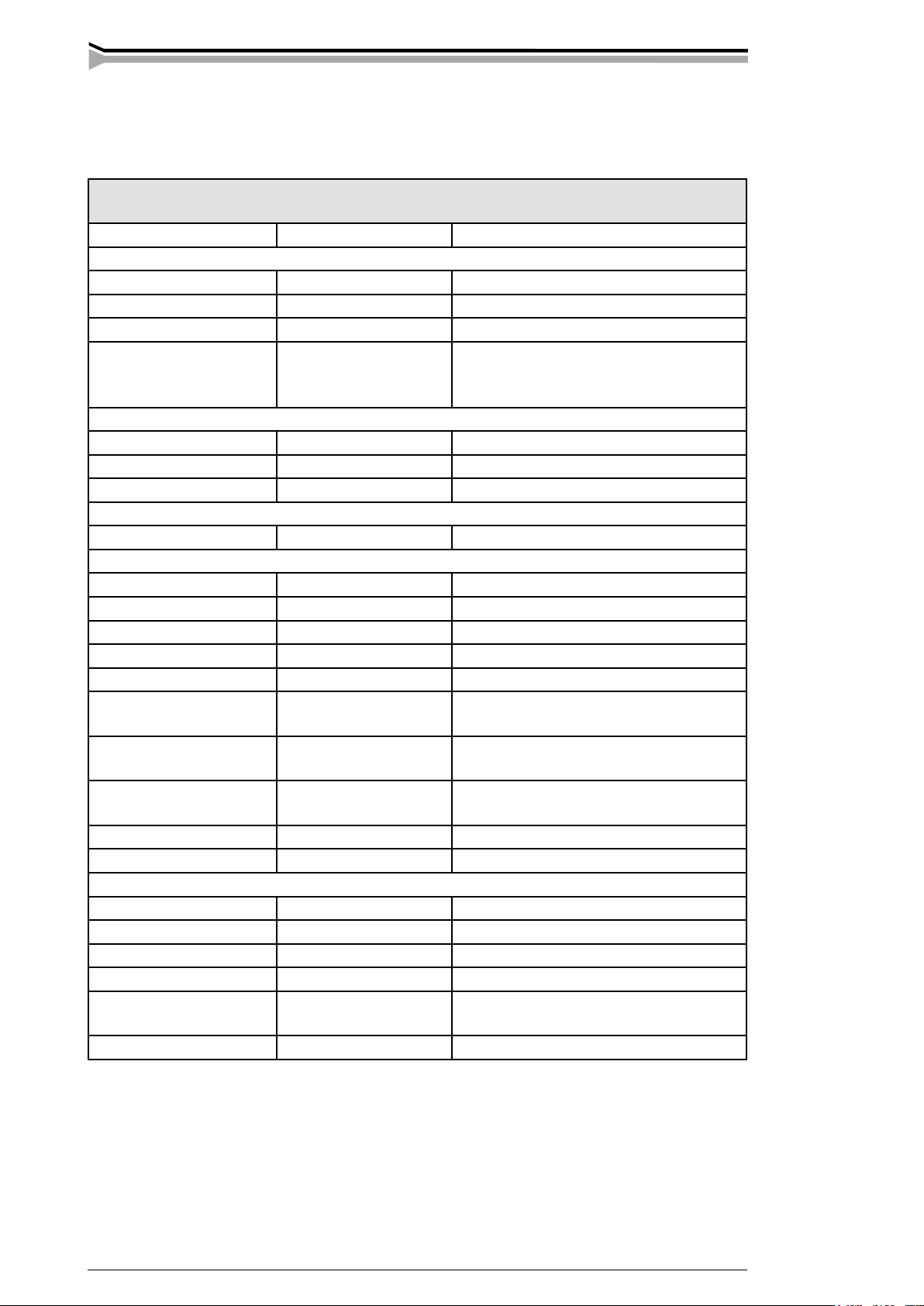
8. TECHNICAL DATA
Kemppi WeldForce
KPS 3500
Mains voltage KPS 3~50/60 Hz 480 V, -10 %...+10 %
Rated power
60 % ED -
80 % ED 15 kVA
100 % ED 13,5 kVA
Connection cable/fuse
delayed
KPS
4 x 6 mm² (10 AWG) S, 5 m (16.4 ft )/ 25 A
Max. welding voltage 40 0C
60 % ED -
80 % ED 350 A
100 % ED 320 A
Max. welding voltage 20 0C
100 % ED 320 A
Welding current range
MMA 10 A ... 350 A
MIG 10 V ... 32 V
Max. welding voltage 46 V / 300 A
Open circuit voltage n. 65 V
Open circuit power < 75 W
Efficiency
at nominal values
n. 85 %
Storage temperature
range
-40...+60˚C (-40 ... +140 0F)
Operating
temperature range
-20...+40˚C (-4 ... +104 0F)
Temperature class H 180 ˚C (356 0F) / B 130 ˚C (266 0F)
Degree of protection IP 23 C
External dimensions
length 690 mm (2.26 ft)
width 230 mm (0.75 ft)
height 520 mm (1.70 ft)
Weight 37 kg (81.6 lb)
Voltage supply for
auxiliary devices
50 V DC
X 14, X 15 fuse 6.3 A delayed
Page 13

KEMPPI OY
PL 13
FIN – 15801 LAHTI
FINLAND
Tel (03) 899 11
Telefax (03) 899 428
www.kemppi.com
KEMPPIKONEET OY
PL 13
FIN – 15801 LAHTI
FINLAND
Tel (03) 899 11
Telefax (03) 7348 398
e-mail: myynti.fi @kemppi.com
KEMPPI SVERIGE AB
Box 717
S – 194 27 UPPLANDS VÄSBY
SVERIGE
Tel (08) 59 078 300
Telefax (08) 59 082 394
e-mail: sales.se@kemppi.com
KEMPPI NORGE A/S
Postboks 2151, Postterminalen
N – 3103 TØNSBERG
NORGE
Tel 33 34 60 00
Telefax 33 34 60 10
e-mail: sales.no@kemppi.com
KEMPPI DANMARK A/S
Literbuen 11
DK – 2740 SKOVLUNDE
DANMARK
Tel 44 941 677
Telefax 44 941 536
e-mail:sales.dk@kemppi.com
KEMPPI BENELUX B.V.
Postbus 5603
NL – 4801 EA BREDA
NEDERLAND
Tel (076) 5717 750
Telefax (076) 5716 345
e-mail: sales.nl@kemppi.com
KEMPPI (UK) Ltd
Martti Kemppi Building
Fraser Road
Priory Business Park
BEDFORD, MK443WH
ENGLAND
Tel 0845 6444201
Fax 0845 6444202
e-mail: sales.uk@kemppi.com
KEMPPI FRANCE S.A.
S.A. au capital de 5 000 000 F.
65 Avenue de la Couronne des Prés
78681 EPONE CEDEX
FRANCE
Tel (01) 30 90 04 40
Telefax (01) 30 90 04 45
e-mail: sales.fr@kemppi.com
KEMPPI GmbH
Otto – Hahn – Straße 14
D – 35510 BUTZBACH
DEUTSCHLAND
Tel (06033) 88 020
Telefax (06033) 72 528
e-mail:sales.de@kemppi.com
KEMPPI SP. z o.o.
Ul. Piłsudskiego 2
05-091 ZA¸BKI
Poland
Tel +48 22 781 6162
Telefax +48 22 781 6505
e-mail: info.pl@kemppi.com
KEMPPI WELDING
MACHINES AUSTRALIA PTY LTD
P.O. Box 404 (2/58 Lancaster Street)
Ingleburn NSW 2565, Australia
Tel. +61-2-9605 9500
Telefax +61-2-9605 5999
e-mail: info@kemppi.com.au
Ver. 8
www.kemppi.com
 Loading...