

Page 1
MagTrac
F 61
Operating manual
Käyttöohje
Bruksanvisning
Bruksanvisning
Brugsanvisning
Gebrauchsanweisung
Gebruiksaanwijzing
Manuel d’utilisation
Manual de instrucciones
Instrukcja obsługi
Инструкции по эксплуатации
EN
FI
SV
NO
DA
DE
NL
FR
ES
PL
RU
Manual de utilização
Manuale d’uso
PT
IT
Page 2

Page 3

OPERATING MANUAL
English
EN
Page 4

EN
CONTENTS
1. Introduction ....................................................................................................... 3
1.1 General ....................................................................................................................................... 3
1.2 About the product ................................................................................................................. 3
1.3 Operation safety ..................................................................................................................... 3
1.4 Compatibility ........................................................................................................................... 3
1.5 Product parts ............................................................................................................................ 4
2. Preparing the carriage for use .....................................................................4
2.1 Welding machine connections ......................................................................................... 4
2.2 MagTrac F 61 connections .................................................................................................. 5
2.3 Working environment ......................................................................................................... 7
3. Using the control panel ................................................................................. 9
3.1 Control panel buttons .......................................................................................................... 9
3.2 Starting up the control panel ........................................................................................... 9
3.3 Control panel menus...........................................................................................................10
3.3.1 MagTrac F 61 main menu ..............................................................................................10
3.3.2 Memory channel selections (MEMORY CH) .................................................................11
3.3.3 Travel speed selections ( ) ......................................................................................11
3.3.4 Wire feed speed selections ( ) ................................................................................11
3.3.5 Welding current selections (CURRENT) .......................................................................11
3.3.6 Welding voltage selections (VOLTAGE) .......................................................................12
3.3.7 Welding arc selections (ARC ON) .................................................................................12
3.3.8 Cycle weld selections ( CYCLE WELD) ....................................................................12
3.3.9 Gas test selections ( GAS TEST) ...............................................................................12
3.3.10 Wire inch selections (WIRE INCH) .................................................................................12
3.3.11 Weld data selections (WELD DATA) ..............................................................................13
3.3.12 Setup selections (SETTINGS) .........................................................................................13
4. Disposal of the machine ..............................................................................14
5. Ordering codes ............................................................................................... 14
6. Technical data ................................................................................................. 16
2
MagTrac F 61
Page 5

1. INTRODUCTION
1.1 General
Congratulations on choosing the MagTrac F 61 equipment. Used correctly, Kemppi products
can signicantly increase the productivity of your welding, and provide years of economical
service.
This operating manual contains important information on the use, maintenance and safety of
your Kemppi product. The technical specications of the equipment can be found at the end
of the manual.
Please read the operating manual and the safety instructions booklet carefully before using
the equipment for the rst time. For your own safety and that of your working environment,
pay particular attention to the safety instructions in the manual.
For more information on Kemppi products, contact Kemppi Oy, consult an authorised Kemppi
dealer, or visit the Kemppi web site at www.kemppi.com.
For Kemppi’s standard safety instructions and warranty terms and conditions, please visit our
web site at www.kemppi.com.
The specications presented in this manual are subject to change without prior notice.
Important notes
Items in the manual that require particular attention in order to minimise damage and
personal harm are indicated with the ’NOTE!’ notation. Read these sections carefully and follow
their instructions.
EN
Disclaimer
While every eort has been made to ensure that the information contained in this guide
is accurate and complete, no liability can be accepted for any errors or omissions. Kemppi
reserves the right to change the specication of the product described at any time without
prior notice. Do not copy, record, reproduce or transmit the contents of this guide without
prior permission from Kemppi.
1.2 About the product
MagTrac F 61 is a welding carriage for mechanisation of longitudinal MIG/MAG welding
applications. Used in combination with the high quality process control system of Kemppi
FastMig welding equipment, the MagTrac F 61 is an easy and ecient way of improving the
welding productivity and quality.
The MagTrac F 61 is equipped with Kemppi's unique welding gun quick-xing mechanism
(patent pending), which makes it quick and easy to set up and adjust the carriage.
1.3 Operation safety
When using the carriage in applications where weakened magnetic force may pose a threat of
the carriage falling down, make sure that such possible accident can not cause any hazard to
people or equipment.
Read also the safety guide delivered in the MagTrac F 61 product package.
NOTE! Welding heat can little by little weaken the carriage's magnetic force.
1.4 Compatibility
MagTrac F 61 is compatible with the following welding equipment
• FastMig KMS 300 and 400 power sources
• FastMig Pulse 350 and 450 power sources
• MXF 65 wire feed unit
• Control panels SF 52W and SF 53W.
© Kemppi Oy / 1131
3
Page 6
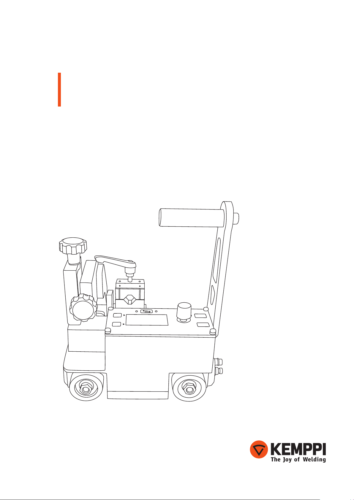
1.5 Product parts
Front view Side view
5.
1. 2.
7.
4.
3.
EN
8.9.
1. Control panel
2. Control knob for scrolling and selecting values
3. Welding gun xing mechanism
4. Approximate adjustment handles
5. Fine adjustment screws
6. Hex screws for adjusting the guide roller arms
7. Handle for lifting the device and disabling the magnet.
8. Limit switch detects the end of the weld and stops the carriage automatically
9. Wheels
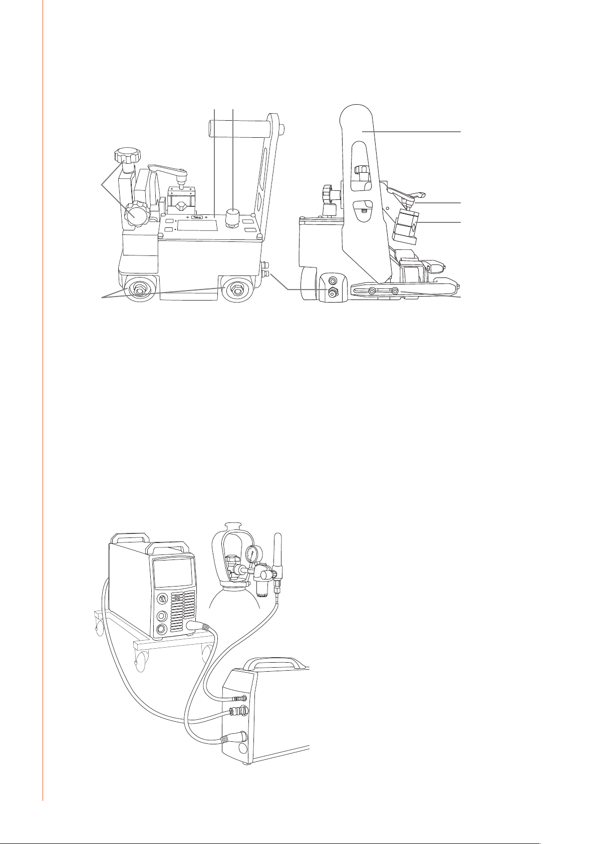
2. PREPARING THE CARRIAGE FOR USE
2.1 Welding machine connections
To use the MagTrac F 61, you need a FastMig power source, wire feeder, and a shielding gas
cylinder or other source of shielding gas appropriate for your welding task.
6.
4
MagTrac F 61
Page 7

Connect the wire feeder to power source as follows:
1. Connect the welding cable between the plus pole of the power source and the cable
connector on the backside of the wire feeder.
2. Connect the control cable between the power source and the wire feeder (the
connectors are on the backside of the machines).
3. Connect the shielding gas hose between the gas cylinder and the wire feeder (the
connector is on the backside of the wire feeder).
2.2 MagTrac F 61 connections
Attach the welding power cable to the Euro connector and the control cable to the data
connector either in the wire feeder unit or in Kemppi SuperSnake subfeeder. See the pictures
below.
EN
To connect the welding gun to MagTrac device:
The MagTrac F 61 is equipped with Kemppi's unique welding gun quick-xing mechanism.
1. Loosen the slide block xing screw (1) and open it a few rounds so that the slide block (2)
comes out.
2. Put the welding gun into the slot and replace the slide block.
3. Tighten the gun into its place using the xing screw.
4. Attach the control cable to the bus connector on the carriage.
1.
2.
© Kemppi Oy / 1131
5
Page 8

EN
Adjust the position of the carriage against the wall:
1. If necessary, change the position of the welding gun mechanism on the carriage by
opening the two hex screws (see the picture).
2. Adjust the position of the carriage so that it slightly pushes against the wall when
moving. To accomplish this, set the guide roller arms so that the front arm is a little
shorter than the back arm.
2.
Adjust the welding gun position:
1. Loosen the orange handles (1 and 2) and make approximate adjustment of the welding
gun position.
NOTE! You can use the adjustment handle like a ratchet wrench by lifting the handle and
turning it to a better position.
2. To ne adjust the gun position, change the distance and height of the welding gun with
the adjustment knobs (see the picture).
NOTE! You can use the ne adjustment knobs also when the carriage is moving.
1.
6
MagTrac F 61
Page 9

2.3 Working environment
Kemppi MagTrac F 61 welding carriage is equipped with a strong magnet that keeps it steadily
in it's track also if you drive the device uphill or downhill.
EN
max. 60°
You can also use the MagTrac F 61 on curved surfaces.
ø > 3000 mmø > 2000 mm
© Kemppi Oy / 1131
7
Page 10

EN
Wide range of adjustments
MagTrac F 61 oers a wide range of adjustments. For example, you can turn the guide roller
arms 180° to point outwards if you need to improve visibility to the welding arc, or you can
swing the welding gun over the side (see the picture).
NOTE! The limit switch might not work if you change the position of the roller arms or welding gun
mechanism. This may prevent the carriage from stopping automatically in the end of the weld.
Activating and releasing magnet
When you lift the handle to its up position in order to move the device, the magnet is
automatically inactivated.
When you place the device to its welding position, you just push the handle down, and the
magnet is automatically activated.
Magnet activated Magnet inactivated
8
MagTrac F 61
Page 11

3. USING THE CONTROL PANEL
MagTrac F 61 control panel allows you to view and adjust the welding parameter values.
You can use the values stored in the memory channels of the wire feeder, or you can set the
desired values on the welding carriage without using the memory channels.
If the memory channel function is active, you can see the channel number on the top row of
the carriage control panel display. The MagTrac F 61 communicates with the wire feeder via a
control cable integrated in the welding gun cable.
3.1 Control panel buttons
1.4.
3.
2.
BACK
HEAT: 0.00 kJ/mm
RESET WELD DATA
RESET
WELD DATA
ARC
ON
START
STOP
6.
5.
MagTrac F 61
1. Multi-function knob for browsing and selecting values
• Turn to scroll menus, press to select values
2. Lower soft key for entering menus and executing commands
• Press to select the active menu item
3. Upper soft key for exiting menus and approving selections
• Press to approve the selected value and to return to the previous menu level
4. Direction button
• Press briey to change the carriage travel direction
• Push for at least 3 seconds to reverse the direction of the display
(this helps the menu usage when MagTrac runs along vertical surface)
5. Start and stop button
• Press this button to start or stop the welding operation
6. Welding arc on/o button
• Press this button to turn the welding arc on and o. With the welding arc o, you can
test the carriage operation
NOTE! When making selections in the MagTrac F 61 menu, you can use a quick shortcut: Turn and
press the multi-function knob 1 instead of pressing soft keys 2 and 3.
EN
3.2 Starting up the control panel
When you start the welding system from the power source's main switch, the system turns on
and the MagTrac F 61 welding carriage is ready for use.
You can inactivate the system with a long press of the wire feeder's ON/OFF button. When the
system is inactive, the carriage cannot be used for welding.
PANEL OFF
Press wire feeder
on/off button
© Kemppi Oy / 1131
MEMORY CH
300 mm/min
5.0 m/min
SET
CH OFF
9
Page 12

EN
ARC
ON
START
STOP
MagTrac F 61
3.3 Control panel menus
CH OFF
MEMORY CH
300 mm/min
5.0 m/min
SET
To browse menu items, turn the multi-function knob 1.
To select the highlighted menu item, press the multi-function knob 1.
• The selected active menu items are marked with a solid box.
• The Selected inactive menu items are marked with a dotted box. You cannot changed
the values of these menu items.
3.3.1 MagTrac F 61 main menu
Menu item Description
MEMORY CH Load and save memory channels.
300 mm/min
5.0 m/min
CURRENT: Change the welding current.
VOLTAGE: Change the welding voltage.
FINETUNING: Fine tune the welding values.
BASECURRENT: Set the base current value.
ARC ON: Enable or disable the welding arc. When this function is OFF, you can test the carriage operation
CYCLE WELD
GAS TEST
WIRE INCH Drive the ller wire into the gun.
WELD DATA Check the weld data recorded from the last welding session.
SETTINGS Open MagTrac F 61 settings menu.
Change the carriage travel speed.
The selected speed is shown in the menu name.
Change the wire feed speed.
The selected speed is shown in the menu name.
The selected current is shown in the menu name.
The selected voltage is shown in the menu name.
(Available only when using pulsed or double-pulsed welding process.)
(Available only when using WiseRoot or WiseThin welding process.)
without igniting the welding arc. (Note that this function is the same as pressing the ARC ON
button.)
Open the cycle weld submenu, where you can enable or disable the cycle weld function and set
its parameters.
Run the gas test.
10
MagTrac F 61
Page 13

3.3.2 Memory channel selections (MEMORY CH)
Menu item Values Description
CH MODE * ON, OFF, SET Select the memory channel usage mode.
ON = Memory channels are enabled, and you can select the
channel to be used. Parameters can be edited on the carriage
panel
OFF = Memory channels are disabled. You can set the welding
parameters on the carriage panel, but they are not stored in the
memory.
SET = Memory channel contents can be edited and saved. You
can change the welding parameters and save your changes into
the active memory channel.
LOAD CH 0…9 Select memory channel to load. Enabled only when CH MODE
selection is ON.
SAVE CH * 0…9 Select memory channel to save. Enabled only when CH MODE
selection is SET.
*) These menu items are not available with FastMig Pulse. CH MODE setting is always ON, and
the channel parameter values are saved automatically.
To change the memory channel in use, do the following
1. In MEMORY CH menu, select CH MODE: ON.
2. In MEMORY CH menu, select LOAD CH and press the multi-function knob.
3. Turn the multi-function knob to select the memory channel number you want to use.
(You can scroll numbers also with the lower soft key 'CH'.)
4. When the desired channel number is displayed, press the upper soft key 'BACK'.
NOTE! If the welding parameter values come from a memory channel, you cannot change any of
the values at the MagTrac menu while operating the carriage.
EN
3.3.3 Travel speed selections ( )
Select this menu item to change the carriage travel speed in the range of 150 - 1500 mm/min.
In cycle welding, the carriage travels non-welded sections at the maximum speed of 1800
mm/min.
NOTE! When the speed reaches 1000 mm/min, the unit of measure changes automatically to
m/min.
To change carriage travel speed, do the following
1. Press the multi-function knob on the travel speed menu item.
2. Turn the multi-function knob to change the speed.
3. Press the multi-function knob to accept the new speed.
3.3.4 Wire feed speed selections ( )
Select this menu item to change the wire feed speed. Note that the welding current value
changes automatically to reect the new wire feed speed.
To change wire feed speed, do the following
1. Press the multi-function knob on the wire feed speed menu item.
2. Turn the multi-function knob to change the speed.
3. Press the multi-function knob to accept the new speed.
3.3.5 Welding current selections (CURRENT)
Select this menu item to change the welding current. Note that the wire feed speed value
changes automatically to reect the new welding current.
To change welding current, do the following
1. Press the multi-function knob on the CURRENT menu item.
2. Turn the multi-function knob to change the current value.
3. Press the multi-function knob to accept the new current.
© Kemppi Oy / 1131
11
Page 14

EN
3.3.6 Welding voltage selections (VOLTAGE)
Select this menu item to change the welding voltage.
To change welding voltage, do the following
1. Press the multi-function knob on the VOLTAGE menu item.
2. Turn the multi-function knob to change the voltage value.
3. Press the multi-function knob to accept the new voltage.
NOTE! Voltage selection may be replaced by either FINETUNING (in pulsed or double-pulsed
processes) or BASECURRENT (in WiseRoot or WiseThin processes) setting.
3.3.7 Welding arc selections (ARC ON)
You can use this menu item to test MagTrac F 61 operation before starting the actual welding.
When the welding arc is OFF, the carriage performs the operations without igniting the
welding arc.
To turn the welding arc on or o, do the following
1. Press the multi-function knob on the ARC ON menu item.
2. Turn the multi-function knob to select ON or OFF.
3. Press the multi-function knob to accept the value.
NOTE! You can also use the ARC ON button turn the welding arc on and o.
3.3.8 Cycle weld selections ( CYCLE WELD)
With MagTrac F 61 you can use the cycle welding function, which means that the carriage
repeatedly welds a predened length and then skips another predened length.
In CYCLE WELD menu you can dene the settings used in cycle welding.
Menu item Values Description
ON, OFF Turn cycle welding on or o.
10mm…10.00m Set the length of each weld.
CYCLE COUNT CONT, 1…255 Set the number of cycles to be welded
When cycle welding is on, there is a cycle weld symbol ( ) in the top right corner of the
MagTrac F 61 control panel display.
NOTE! Crater ll feature is available in wire feeder control panel.
10mm…2.00m Set the length of the non-weld section between the welds.
3.3.9 Gas test selections ( GAS TEST)
Select this menu item to test the gas ow. First select the menu item, and then start the gas
ow by pressing the multi-function knob or the soft key START. The shielding gas ows for 10
seconds.
NOTE! You can interrupt the gas ow at any time by clicking the multi-function knob or the soft key
STOP.
3.3.10 Wire inch selections (WIRE INCH)
Select this menu item to run the ller wire into the welding gun. In MagTrac F 61, the wire inch
speed is always the same as the selected wire feed speed.
NOTE! If the wire inch function is activated on the wire feeder's panel, the wire inch function on
MagTrac is not available.
– CONT means that the carriage continues cycle welding
continuously, until it is stopped.
12
MagTrac F 61
Page 15

3.3.11 Weld data selections (WELD DATA)
MagTrac F 61 records useful information about the latest welding session. Select Weld data
menu to check the data.
Menu item Description
Length of the latest weld.
TOT ARC (m) Total welded length of the latest welding session.
Does not include the non-weld length in cycle welding.
TOT ARC (min, s) Total time of the latest welding session.
Does not include the non-weld time in cycle welding.
CURRENT Average welding current during the latest welding session.
VOLTAGE Average welding voltage during the latest welding session.
HEAT Heat input in the latest welding session in kJ/mm.
RESET WELD DATA This resets all weld data settings.
3.3.12 Setup selections (SETTINGS)
Select this menu to check or change the MagTrac F 61 settings. The settings are stored in the
carriage memory.
Menu item Values Description
CONTRAST
RESTORE SETTINGS YES, NO Restore the parameter values to their initial settings.
PANEL INFO PANEL SW
SYSTEM SW
PRG DATE
EN
Change the contrast of the carriage display.
Open information about the carriage software: Control panel
version, system version and the date of the carriage software.
Initial parameter settings
When you use the RESTORE SETTINGS function, the parameter settings are restored to the
following values:
Parameter Factory value
ARC ON OFF (welding arc is o)
DIRECTION RIGHT (carriage travels to the right)
CONTRAST 20 (contrast of the control panel display)
CYCLE WELD OFF (cycle welding is not in use)
WELD LENGTH 50 mm (length of the welded section in cycle welding).
IDLE LENGTH 50 mm (length of the non-welded section in cycle welding).
CYCLE COUNT CONT (cycle welding continues until it is stopped )
LAST WELD LENGTH 0 mm
TOT ARC 0 mm (total arc length in the latest welding session)
TOT ARC 0 min 0 s (total arc time in the latest welding session)
CURRENT 0 A (average current in the latest welding session)
VOLTAGE 0 V (average voltage in the latest welding session)
HEAT 0.0 kJ/mm (heat input in the latest welding session)
© Kemppi Oy / 1131
13
Page 16

EN
4. DISPOSAL OF THE MACHINE
Do not dispose of electrical equipment with normal waste!
In observance of European Directive 2002/96/EC on waste electrical and electronic
equipment, and its implementation in accordance with national law, electrical equipment
that has reached the end of its life must be collected separately and taken to an appropriate
environmentally responsible recycling facility.
The owner of the equipment is obliged to deliver a decommissioned unit to a regional
collection centre, per the instructions of local authorities or a Kemppi representative. By
applying this European Directive you will improve the environment and human health.
5. ORDERING CODES
MagTrac F61, FastMig KMS, air-cooled P08818
FastMig KMS 400 power source 6054000
FastMig MXF 65 wire feeder 6152100
FastMig SF 53W control panel 6085300W
PM 500 undercarriage 6185291
MMT 42 C welding gun 3 m 6254205
KWF 70-5-GH interconnection cable 6260405
Earth return cable 50 mm², 5 m 6184511
MagTrac F61 welding carriage 6190610
MagTrac F61, FastMig KMS, SuperSnake, air-cooled P08819
FastMig KMS 400 power source 6054000
FastMig MXF 65 wire feeder 6152100
FastMig SF 53W control panel 6085300W
PM 500 undercarriage 6185291
MMT 42 C welding gun 3 m 6254205
MXF SYNC mounting kit W004030
SuperSnake GT 02SC 15 m 61531501
KWF 70-1.8-GH interconnection cable 6260401
Earth return cable 50 mm², 5 m 6184511
MagTrac F61 welding carriage 6190610
MagTrac F61, FastMig Pulse, air-cooled P08822
FastMig Pulse 450 power source 6150500
FastMig MXF 65 wire feeder 6152100
FastMig Pulse PF 65 control panel 6155100
PM 500 undercarriage 6185291
MMT 42 C welding gun 3 m 6254205
KWF 70-5-GH interconnection cable 6260405
Earth return cable 50 mm², 5 m 6184511
MagTrac F61 welding carriage 6190610
14
MagTrac F 61
Page 17

MagTrac F61, FastMig Pulse, SuperSnake, air-cooled P08828
FastMig Pulse 450 power source 6150500
FastMig MXF 65 wire feeder 6152100
FastMig Pulse PF 65 control panel 6155100
PM 500 undercarriage 6185291
MMT 42 C welding gun 3 m 6254205
MXF SYNC mounting kit W004030
SuperSnake GT 02SC 15 m 61531501
KWF 70-1.8-GH interconnection cable 6260401
Earth return cable 50 mm², 5 m 6184511
MagTrac F61 welding carriage 6190610
MagTrac F61, FastMig KMS, liquid-cooled P08826
FastMig KMS 400 power source 6054000
FastMig MXF 65 6152100
FastMig SF 53W 6085300W
FastCool 10 6068100
PM 500 undercarriage 6185291
MT51MWC welding gun 4,5 m 6255162
KWF 70-5-WH interconnection cable 6260410
Earth return cable 50 mm², 5 m 6184511
MagTrac F61 welding carriage 6190610
EN
MagTrac F61, FastMig Pulse, liquid-cooled P08827
FastMig Pulse 450 power source 6150500
FastMig MXF 65 wire feeder 6152100
FastMig Pulse PF 65 control panel 6155100
FastCool 10 cooling unit 6068100
PM 500 undercarriage 6185291
MT51MWC welding gun 4.5 m 6255162
KWF 70-5-WH interconnection cable 6260410
Earth return cable 50 mm², 5 m 6184511
MagTrac F61 welding carriage 6190610
Optional:
SuperSnake GT 02SC 15 m 61531501
FastMig KMS 300 power source 6053000
FastMig MXF 63 wire feeder 6152300
MMT 42 C welding gun 4.5 m 6254207
Control extension cable 6 m W005871
MT51MWC welding gun 4,5 m 6255162
© Kemppi Oy / 1131
15
Page 18

EN
6. TECHNICAL DATA
MagTrac F 61
Input power
Data bus type
Travel speed
Towing power
Driving method
Wheels
Tracing method
Guide roller height range
Non-welding distance
Auto-stop function
Welding gun
Gun angle adjustment range
Gun distance adjustment range
External dimensions
Weight
Max surface temperature
EMC class
Degree of protection
Operating temperature range
Storage temperature range
Standards IEC 60204-1 and partially IEC 60974-1
50 VDC / 1 A
KempBus
150–1800 mm/min
30 kg
Rail-less drive with permanent
magnetic suction
4 rubber wheels
Guide rollers
10–38 mm, 3 positions
Start 127 mm
End 127 mm
Limit switch on both sides
Kemppi MMT 42C
+/–30°
vertical, horizontal 45 mm
L x W x H 259 x 259 x 285 mm
6.9 kg
150 °C
A
IP2X
–20…+40 °C
–40…+60 °C
16
MagTrac F 61
Page 19

Page 20

KEMPPI OY
Kempinkatu 1
PL 13
FIN-15801 LAHTI
FINLAND
Tel +358 3 899 11
Telefax +358 3 899 428
export@kemppi.com
www.kemppi.com
Kotimaan myynti:
Tel +358 3 899 11
Telefax +358 3 734 8398
myynti.@kemppi.com
KEMPPI SVERIGE AB
Box 717
S-194 27 UPPLANDS VÄSBY
SVERIGE
Tel +46 8 590 783 00
Telefax +46 8 590 823 94
sales.se@kemppi.com
KEMPPI NORGE A/S
Postboks 2151, Postterminalen
N-3103 TØNSBERG
NORGE
Tel +47 33 346000
Telefax +47 33 346010
sales.no@kemppi.com
KEMPPI DANMARK A/S
Literbuen 11
DK-2740 SKOVLUNDE
DANMARK
Tel +45 4494 1677
Telefax +45 4494 1536
sales.dk@kemppi.com
KEMPPI BENELUX B.V.
Postbus 5603
NL-4801 EA BREDA
NEDERLAND
Tel +31 765717750
Telefax +31 765716345
sales.nl@kemppi.com
KEMPPI (UK) Ltd
Martti Kemppi Building
Fraser Road
Priory Business Park
BEDFORD, MK44 3WH
UNITED KINGDOM
Tel +44 (0)845 6444201
Telefax +44 (0)845 6444202
sales.uk@kemppi.com
KEMPPI FRANCE S.A.S.
65 Avenue de la Couronne des Prés
78681 EPONE CEDEX
FRANCE
Tel +33 1 30 90 04 40
Telefax +33 1 30 90 04 45
sales.fr@kemppi.com
KEMPPI GmbH
Otto-Hahn-Straße 14
D-35510 BUTZBACH
DEUTSCHLAND
Tel +49 6033 88 020
Telefax +49 6033 72 528
sales.de@kemppi.com
KEMPPI SPÓŁKA Z O.O.
Ul. Borzymowska 32
03-565 WARSZAWA
POLAND
Tel +48 22 7816162
Telefax +48 22 7816505
info.pl@kemppi.com
KEMPPI AUSTRALIA PTY LTD.
13 Cullen Place
P.O. Box 5256, Greystanes NSW 2145
SMITHFIELD NSW 2164
AUSTRALIA
Tel. +61 2 9605 9500
Telefax +61 2 9605 5999
info.au@kemppi.com
OOO KEMPPI
Polkovaya str. 1, Building 6
127018 MOSCOW
RUSSIA
Tel +7 495 739 4304
Telefax +7 495 739 4305
info.ru@kemppi.com
ООО КЕМППИ
ул. Полковая 1, строение 6
127018 Москва
Tel +7 495 739 4304
Telefax +7 495 739 4305
info.ru@kemppi.com
KEMPPI, TRADING (BEIJING) COMPANY,
LIMITED
Room 420, 3 Zone, Building B,
No.12 Hongda North Street,
Beijing Economic Development Zone,
100176 Beijing
CHINA
Tel +86-10-6787 6064
+86-10-6787 1282
Telefax +86-10-6787 5259
sales.cn@kemppi.com
肯倍贸易(北京)有限公司
中国北京经济技术开发区宏达北路12号
创新大厦B座三区420室 (100176)
电话: +86-10-6787 6064
+86-10-6787 1282
传真: +86-10-6787 5259
sales.cn@kemppi.com
KEMPPI INDIA PVT LTD
LAKSHMI TOWERS
New No. 2/770,
First Main Road,
Kazura Garden,
Neelankarai,
CHENNAI - 600 041
TAMIL NADU
Tel +91-44-4567 1200
Telefax +91-44-4567 1234
sales.india@kemppi.com
1920200
1131
www.kemppi.com
 Loading...