

Page 1

Operating manual • English
Käyttöohje • Suomi
Bruksanvisning • Svenska
Bruksanvisning • Norsk
Brugsanvisning • Dansk
Gebrauchsanweisung • Deutsch
Gebruiksaanwijzing • Nederlands
Manuel d’utilisation • Français
Manual de instrucciones • Español
Instrukcja obsługi • Polski
Инструкции по эксплуатации • По-русски
EN
FI
SV
NO
DA
DE
NL
FR
ES
PL
RU
Kempomat
2500, 3200, 4200
Page 2

Page 3

OPERATING MANUAL
English
Kempomat 2500, 3200, 4200 / © Kemppi Oy / 1117
Page 4

EN
CONTENTS
1. PREFACE
........................................................................................................................................................ 3
1.1 General
................................................................................................................................................................. 3
1.2 Product introduction
................................................................................................................................. 3
2. INSTALLATION OF THE POWER SOURCE ........................................................... 4
2.1 Positioning of the machine ...................................................................................................................4
2.2 Connection to the mains supply ....................................................................................................... 4
2.3 Mounting of the mains cable .............................................................................................................. 4
2.4 Welding and return current cables ..................................................................................................5
3. USE OF WIREFEEDER ....................................................................................................................6
3.1 Parts of wire feed mechanism
............................................................................................................. 6
3.2 Installation of the wire feed system
................................................................................................ 8
3.3 Installation of wire feed ........................................................................................................................... 8
3.4 Mounting of MIG welding gun
........................................................................................................... 9
3.5 Mounting and locking of wire reel
.................................................................................................. 9
3.6 Automatic wire feed to gun
............................................................................................................... 10
3.7 Adjustment of tightness of wire reel brake
............................................................................ 10
3.8 Shielding gas ................................................................................................................................................ 11
4. OPERATION AND USE OF POWER SOURCE .................................................12
4.1 Kempomat panels .....................................................................................................................................12
4.2 Wire feed panel ...........................................................................................................................................13
4.3 Wire feeder unit ..........................................................................................................................................13
4.4 Main switches and pilot lamps ........................................................................................................ 14
4.5 Adjustment for arc roughness .........................................................................................................15
4.6 Operation of cooling fan ...................................................................................................................... 15
5. CONTROL PANELS AND ADJUSTMENTS .........................................................15
5.1 Wire feed speed potentiometer .....................................................................................................15
5.2 Burn back time
............................................................................................................................................ 15
5.3 KMW timer functions .............................................................................................................................. 16
6. ACCESSORIES ......................................................................................................................................17
6.1 KMW sync ........................................................................................................................................................ 17
6.2 Installation and mounting of KMW sync .................................................................................. 17
7. OPERATION DISTURBANCES ..........................................................................................18
8. REGULAR MAINTENANCE OF THE EQUIPMENT ....................................18
8.1 Cables ................................................................................................................................................................. 19
8.2 Power source ................................................................................................................................................19
8.3 Disposal of the machine .......................................................................................................................19
9. ORDERING NUMBERS ...............................................................................................................20
10. TECHNICAL DATA ........................................................................................................................... 21
2
Kempomat 2500, 3200, 4200 / © Kemppi Oy / 1117
Page 5

EN
1. PREFACE
1.1 GENERAL
Congratulations on choosing the Kempomat™ equipment. Used correctly, Kemppi products
can signicantly increase the productivity of your welding, and provide years of economical
service.
This operating manual contains important information on the use, maintenance and safety of
your Kemppi product. The technical specications of the equipment can be found at the end
of the manual.
Please read the manual carefully before using the equipment for the rst time. For your
own safety and that of your working environment, pay particular attention to the safety
instructions in the manual.
For more information on Kemppi products, contact Kemppi Oy, consult an authorised Kemppi
dealer, or visit the Kemppi web site at www.kemppi.com.
The specications presented in this manual are subject to change without prior notice.
Important notes
Items in the manual that require particular attention in order to minimise damage and
personal harm are indicated with the ’NOTE!’ notation. Read these sections carefully and follow
their instructions.
Disclaimer
While every eort has been made to ensure that the information contained in this guide
is accurate and complete, no liability can be accepted for any errors or omissions. Kemppi
reserves the right to change the specication of the product described at any time without
prior notice. Do not copy, record, reproduce or transmit the contents of this guide without
prior permission from Kemppi.
1.2 PRODUCT INTRODUCTION
The power sources Kempomat 3200 and 4200 are compact MIG welding machines, designed
for heavy industrial use. Kempomat 2500 is compact MIG welding machine, designed for
repair shops and light and heavy industrial use.
Power source
Supply voltage of the Kempomat 2500 power source is 3~ 230 V/400 V. Supply voltage of the
Kempomat 3200 power source is 3~ 230 V/400 V. Welding voltage adjustment is in 10-steps.
Adjustment for voltage of power source is in 40-steps.
In Kempomat 4200 product range there are dierent units for mains voltages 3~ 230 and 400
V. The welding voltage adjustment for 230 V power source is made in 32 steps, 400V power
source in 56-steps. The Volt/Ampere metering unit MSD 1 (available as accessory) displays
voltage or welding current.
Wire feeder unit
The wire feeder unit is a xed unit in the equipment for air-cooled guns. Kempomat 2500 is
equipped with 2 wheel wire drive mechanism, Kempomat 3200 and 4200 are equipped with
4 wheel wire drive mechanism. Accessory unit KMW sync is needed for connection and use of
push-pull guns.
3
Kempomat 2500, 3200, 4200 / © Kemppi Oy / 1117
Page 6

EN
2. INSTALLATION OF THE POWER SOURCE
2.1 POSITIONING OF THE MACHINE
Place the machine on a rm, dry and level surface. Where possible, do not allow dust or other
impurities to enter the machines cooling air ow. Preferably site the machine above oor level;
for example on a suitable carriage unit.
Notes for positioning the machine
• The surface inclination should not exceed 15 degrees.
• Ensure the free circulation of the cooling air. There must be at least 20 cm of free space in
front of and behind the machine for cooling air to circulate.
• Protect the machine against heavy rain and direct sunshine.
NOTE! The machine should not be operated in the rain as the protection class of the machine,
IP23S, allows for outside preserving and storage only.
NOTE! Never aim metallic grinding spray/sparks towards the equipment.
2.2 CONNECTION TO THE MAINS SUPPLY
Connection and change of the mains cable and the plug must be carried out only by a
competent electrician. Remove for the mounting of the mains cable the left side plate, seen
from the front of the power source.
The Kempomat power source is equipped with 5 m supply cable without plug. The mains
cable is according to the marking H07RN-F of the norm CENELEC HD22. The mains cable must
be changed if it doesn´t meet local regulations.
2.3 MOUNTING OF THE MAINS CABLE
The cable is entered into the machine through the inlet ring on the rear wall of the machine
and locked with a cable clamp (05).
The phase conductors of the cable are coupled to connectors L1, L2 and L3. The earth
protection coloured green-yellow is coupled to connector marked with earth protection
symbol
. If you are using 5-conductor cable, you must cut the zero conductor to the level of
the cable´s protective shield.
In cables of S type there is protective grounding conductor coloured green-yellow.
L1
L2
L3
Kempomat 2500 3200 4200
Connection voltage
230 V 400 V 230 V 400 V 230 V 400 V
Connection cable
4G2.5 (5 m) 4G2.5 (5 m) 4G2.5 (5 m) 4G2.5 (5 m) 4G6.0 (5 m) 4G2.5 (5 m)
Fuse, delayed
16 A 10 A 20 A 16 A 25 A 16 A
4
Kempomat 2500, 3200, 4200 / © Kemppi Oy / 1117
Page 7

EN
Change of mains voltage / Kempomat 2500, 3200
Connection and change of the mains cable and the plug must be carried out only by a
competent electrician.
230 V
201
204
203
206
205
202
230 V
T002
400 V
230 V
0
201
204
203
206
205
202
400 V
400 V
T002
400 V
230 V
0
Connection 3~ 230 or 3~ 400 V of mains voltage
By delivery from the factory the Kempomat 3200 and 2500 machine has been connected for
mains voltage 3~ 400 V. In order to change the mains voltage in the Kempomat 2500/3200
machine, remove the side plate of the machine. Change the connections according to the
enclosed diagram. You nd the corresponding wiring diagram on the instruction label, which
is under terminal block.
NOTE! The Kempomat 4200 machine has the connection for only one mains voltage!
2.4 WELDING AND RETURN CURRENT CABLES
In enclosed table are shown typical loading capacities of rubber insulated copper cables,
when ambient temperature is 25 °C and conductor temperature is 85 °C.
Kempomat 2500
Cable cross-section Duty cycle ED Voltage loss / 10 m
Cu 100 % 60 % 30 % for 100 A
25 mm² 180 A 230 A 330 A 0.7 V
35 mm² 225 A 290 A 410 A 0.5 V
Kempomat 3200, 4200
Cable cross-section Duty cycle ED Voltage loss / 10 m
Cu 100 % 60 % 40 % for 100 A
50 mm² 285 A 370 A 450 A 0.35 V
70 mm² 355 A 460 A 560 A 0.25 V
NOTE! Don´t overload welding cables over permissible values due to voltage losses and heating.
Fasten the earthing press of the return current cable carefully, preferably direct onto the piece to
be welded. The contact surface area of the press should always be as large and steady as possible.
Clean the contact surface from paint and rust.
5
Kempomat 2500, 3200, 4200 / © Kemppi Oy / 1117
Page 8
EN
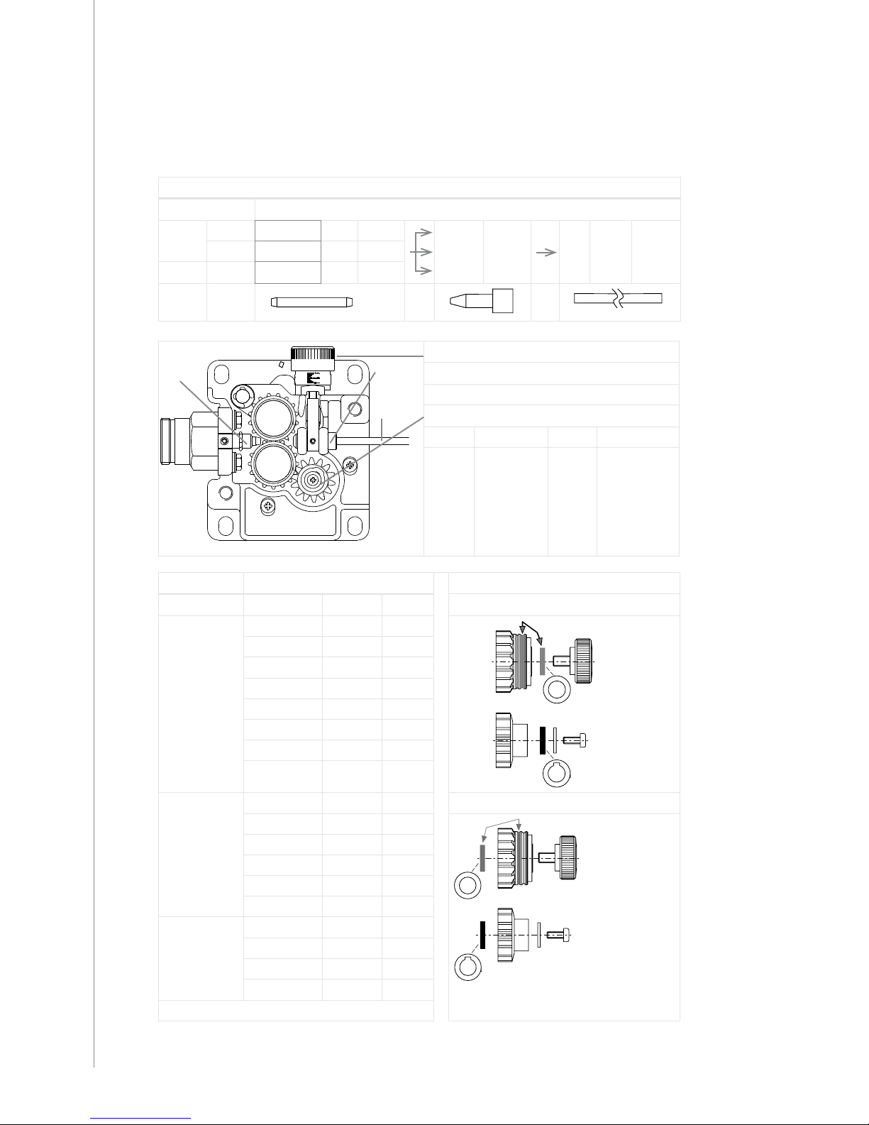
3. USE OF WIREFEEDER
3.1 PARTS OF WIRE FEED MECHANISM
Kempomat 2500
Wire guide tubes for 2-roll wire feed mechanism
Wire ø mm Wire guide tube ø mm
Fe, Mc,
Fc
0,6 ... 0,8 White 1,0 3134140 brass 4285900 1,8 plastic 4102283
0,9 ... 1,6 Orange 2,0 3133700
Ss, Al
0,8 ... 1,6 Silver 2,5 3134290
A.
B.
C.
A. B.
C.
Pressure adjustment
Gear wheel, 2-roll wire feed mechanism
ø 28 mm (0–18 m/min) 4265240 muovi
ø 28 mm (0–18 m/min) 4287860 teräs
Feed rolls 2-roll (2500) 2500, 3200, 4200
Colour ø mm
Feed roll groove selection
Fe, Ss, Al
Plain V-groove
White 0.6/0.8 3133810
White 0.8/0.8 (L) 3143180
Red 3133210
Red 1.0/1.0 (L) 3138650
Orange 1.2/1.2 (L) 3137390
Yellow 1.4-1.6 3133820
Yellow 1.6/1.6 (L) 3141120
Fe, Fc, Mc
Knurled
V-groove
Red 1.0/1.2 3133940 Transfer of gear wheel selector plate
Orange 1.2/1.2 (L) 3137380
Yellow 1.4-1.6 3133990
Yellow 1.6/1.6 (L) 3141130
Fe, Fc, Mc,
Ss, Al
Trapezoid
groove
Orange 1.2/1.2 (L) 3142210
Brown 1.4/1.4 (L) 3142220
Yellow 1.6/1.6 (L) 3142200
(L) = Fitted with ball bearings
6
Kempomat 2500, 3200, 4200 / © Kemppi Oy / 1117
Page 9

EN
Kempomat 3200, 4200
Wire guide tubes for 4-roll wire feed mechanism
Wire ø mm Wire guide tube ø mm
FeMcFc
0.6 ... 0.8 1.0 3134140 Orange 2.0 3134120 plastic 2.0 4267220 yellow 2.4 4268210
plastic 2.0 4266970
0.9 ... 1.6 Orange 2.0 3133700 plastic 4.0 4270180 ProMig 511
1.6 ... 2.4 Blue 4.0 3134130 Blue 4.0 3134110 brass 4.0 4267030
Ss
Al
0.8 ... 1.6 Grey 2.5 3134290 Grey 2.5 3134300 plastic 2.0 4267220 yellow 3.0 4268560
1.6 ... 2.4 Yellow 3.0 3134710 Yellow 3.0 3134720 plastic 4.0 4270180
A. B.
C.
D.
A.
C.
D.
B.
Pressure adjustment
Gear wheel, 4-roll wire feed mechanism
ø 28 mm (0–18 m/min) 4265240 plastic
ø 28 mm (0–18 m/min) 4287860 steel
ø 40 mm (0–25 m/min) 4265250 plastic
ø 40 mm (0–25 m/min) 4297270 steel
Feed rolls 4-roll (3200, 4200) Colour ø mm
Colour ø mm Fe, Fc, Mc
Knurled V-groove
Red 1.0/1.2 3133940
Fe, Ss, Al
Plain V-groove
White 0.6/0.8 3133810 Orange 1.2/1.2 (L) 3137380
White 0.8/0.8 (L) 3143180 Yellow 1.4-1.6/2.0 3133990
Red 1.0/1.2 3133210 Yellow 1.6/1.6 (L) 3141130
Red 1.0/1.0 (L) 3138650 Black 2.4 3134030
Orange 1.2/1.2 (L) 3137390 Blue 3.2 3134060
Yellow 1.4-1.6/2.0 3133820
Fe, Fc, Mc,
Ss, Al
Trapezoid groove
Orange 1.2/1.2 (L) 3142210
Yellow 1.6/1.6 (L) 3141120 Brown 1.4/1.4 (L) 3142220
Black 2.4 3133880 Yellow 1.6/1.6 (L) 3142200
Blue 3.2 3133910 Grey 2.0/2.0 (L) 3142230
(L) = Fitted with ball bearings
Black 2.4 (L) 3142240
7
Kempomat 2500, 3200, 4200 / © Kemppi Oy / 1117
Page 10
EN
3.2 INSTALLATION OF THE WIRE FEED SYSTEM
Wire feeder unit:
1. Mount the return current cable to connector on the Kempomat´s front panel.
2. The MIG gun is mounted to the EURO connector of the wire feeder unit. Use guide tubes
and contact tips according to manufacturer´s operation instructions. Accessories which
are too tight or otherwise unsuitable for the wire type used by you, will cause wire feed
disturbances.
3. Max. wire feed speed
When the unit is delivered the max. wire feed speed is 18 m/min, which is enough for the most
welding works. If you need a higher speed, you can increase the max. wire feed speed to 25 m/
min by replacing the gear wheel on motor shaft to a bigger one. The big gear wheel (D40) is
delivered on order.
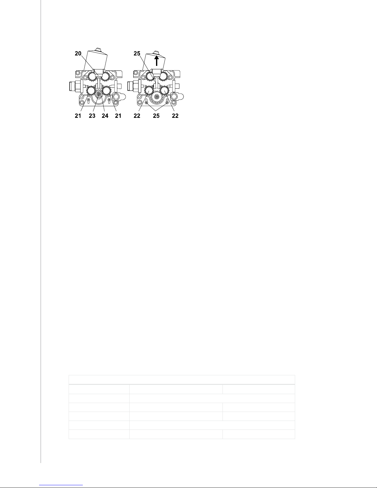
When necessary speed is changed according to following:
• Open tightening lever (20). Remove lower feed rolls (21). Release screw (23) and its
washer. Remove gear wheel D28 (24) from motor shaft.
• Loosen screws (25) (3 pc) 1 twist. Mount the D40 gear wheel onto motor shaft. Screw the
screw (23) with its washer back.
• Put feed rolls (21) back to their axles, however don´t fasten yet fastening screws of the
feed rolls (22).
• Lift the motor so that the tooth gap between gear wheel and both lower feed rolls is
approx. 0,2 mm.
• Tighten screws (25). Check gear teeth gaps, when necessary put the motor into a better
position. Screw on the mounting rolls of feed rolls (22).
• Too small gap between gear wheel and feed rolls will overload motor.
• Too big gap for its part might cause too rapid wearing for teeth of feed rolls and gear
wheel.
4. The shielding gas hose is mounted to the snap connector on the rear wall of the
unit. Mounting to the gas bottle and shielding gas ow regulation, see paragraph for
SHIELDING GAS.
3.3 INSTALLATION OF WIRE FEED
Accessories according to wire feed
Wire feed rolls are available with plain groove, knurled groove and with trapezoidal groove for
dierent purposes.
Kempomat 2500
Colour Filler wire ø, mm inch
Feed rolls
white 0.6 and 0.8 0.030
red 0.9/1.0 and 1.2 0.035, 0.045 and 0.052
Guide tubes
orange 0.6-1.6 0.024-1/16
8
Kempomat 2500, 3200, 4200 / © Kemppi Oy / 1117
Page 11

EN
Kempomat 3200, 4200
Colour Filler wire ø, mm inch
Feed rolls
white 0.6 and 0.8 0.030
red 0.9/1.0 and 1.2 0.035, 0.045 and 0.052
yellow 1.4, 1.6 and 2.0 1/16 and 5/64
Guide tubes
orange 0.6-1.6 0.024-1/16
Feed roll with plain groove:
Universal feed roll for welding of all kinds of wires
Feed rolls with knurled groove:
Special feed roll for cored wires and steel wires
Feed rolls with trapezoidal groove:
Special feed roll for aluminium wires
Wire feed rolls have two grooves for dierent ller wire diameters. Correct wire groove is
selected by moving selecting washer from one side to another in feed roll.
Feed rolls and wire guide tubes have colour codes in order to make identication easier.
By delivery Kempomat is equipped with red feed rolls with plain groove and with orange wire
guide tubes for welding ller wires 0.9 - 1.2 mm (0.035”, 0.045” and 0.052”).
3.4 MOUNTING OF MIG WELDING GUN
In order to ensure trouble-free welding check in operation instructions of gun used by you
that wire guide tube and contact tip of gun are according to manufacturer´s recommendation
suitable to be used for wire feed diameter and type in question. Too tight a wire guide tube
might cause for wire feeder unit a bigger stress than normally as well as disturbances in wire
feed.
Screw snap connector of gun tight that there won´t come any voltage losses on connecting
surface.
A loose connection will heat gun and wire feeder unit.
NOTE! Make sure that the welding gun in your use is designed for max. welding current needed by
you! Never use a damaged welding gun!
3.5 MOUNTING AND LOCKING OF WIRE REEL
• Release locking nails of wire reel hub by turning locking knob to the position OPEN.
• Mount the reel at its place. Note rotating direction of reel!
• Turn the locking knob to the position LOCKED.
NOTE! Check in ller wire reel that there are no parts sticking out, which could e.g. chafe against
chassis or door of wire feeder unit. Dragging parts might expose chassis of wire feeder unit under
voltage.
LOCKED OPEN
9
Kempomat 2500, 3200, 4200 / © Kemppi Oy / 1117
Page 12
EN
3.6 AUTOMATIC WIRE FEED TO GUN
Automatic wire feed makes change of wire reel more rapid. In reel change the pressure of feed
rolls need not to be released and ller wire goes automatically to correct wire line.
• Make sure that groove of feed roll matches the diameter of welding wire used. Feed roll
groove is selected by moving the groove selecting washer. Also the selector plate for
changing the feed roll groove has to be moved similarly. (see tables on pages 6 and 7).
Groove selecting washer
• Release the wire end from reel and cut o the bent length. Be careful that the wire does
not spill from the reel to sides!
• Straighten about 20 cm of the wire and see that the end of it has no sharp edges (le
o if necessary). A sharp edge may damage the wire guide tube and contact tip of the
welding gun.
• Draw a bit of loose wire from wire reel. Feed wire through back liner to feed rolls. Don´t
release pressure of feed rolls!
• Press the gun switch and feed a bit wire until wire goes through feed rolls to gun. See
that wire is in grooves of both feed roll pairs!
• Press still the gun switch until wire has come through contact tip.
Automatic feed may sometimes fail with thin wires (Fe, Ss: 0.6 ... 0.8 mm, Al, Fc: 0.8 ... 1.0 mm).
Then it might be possible that you must open feed rolls and feed wire manually through feed
rolls.
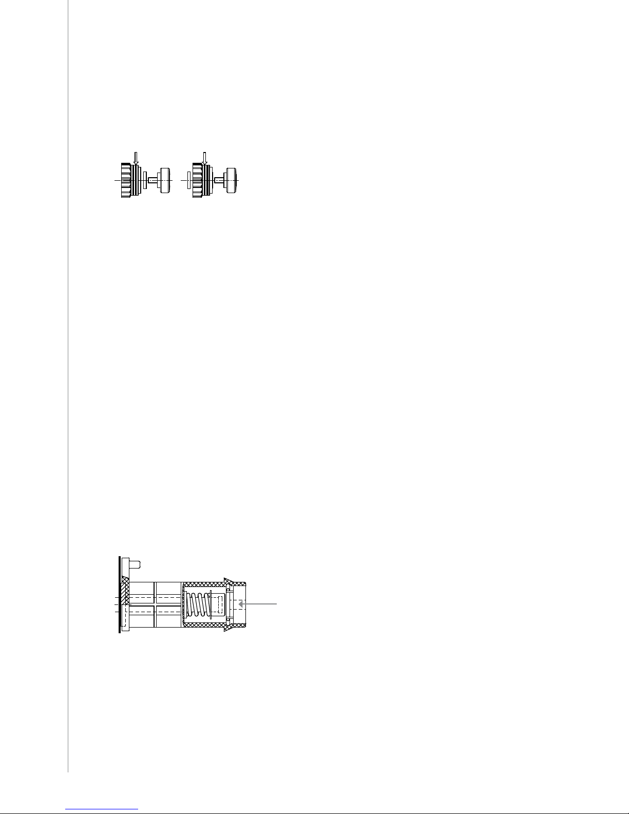
Adjustment of pressure
Adjust the pressure of feed rolls with the control screw (20) so that the wire is fed into the wire
guide tube evenly and allows a little braking when coming out from the contact tip without
slipping at the feed rolls.
NOTE! Excessive pressure causes attening of the ller wire and damage to the coating. It also
causes undue wear of the feed rolls as well as friction.
3.7 ADJUSTMENT OF TIGHTNESS OF WIRE REEL BRAKE
Brake force is adjusted through hole in locking device of reel hub by screwing the control
screw with screwdriver.
Adjust brake force as so big that the wire cannot spill from the reel when the rotation of the
reel stops. Need for brake force is increased with increase of the wire feed speed.
Since the brake loads for its part the motor, you shouldn´t keep it unnecessarily tight.
Adjustment screw
10
Kempomat 2500, 3200, 4200 / © Kemppi Oy / 1117
Page 13
EN
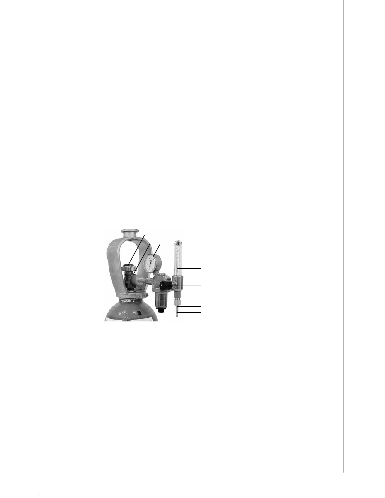
3.8 SHIELDING GAS
As MIG shielding gas is used carbon dioxide, mixed gases and argon. Shielding gas ow rate is
dened by welding current size. Typical rate of gas in welding of steel is 8-15 l / min.
Gas ow regulator
Gas ow regulator should be suitable for shielding gas used by you. The regulator being in
your use might be dierent from the one in picture, however, following general instructions
are valid for all pressure regulators.
Before mounting of ow regulator
1. Step aside and open the bottle valve (A) for a while to blow out possible impurities from
the bottle valve.
2. Turn the press regulation screw (B) of the regulator until no spring pressure can be felt.
3. Close needle valve, if there is one in the regulator.
4. Install the regulator on bottle valve and tighten connecting nut (C) with a wrench.
5. Install hose spindle (D) and jacket nut (E) into gas hose and tighten with hose clamp.
6. Connect the hose with the regulator and the other end with the power source. Tighten
the jacket nut.
7. Open bottle valve slowly. Gas bottle pressure meter (F) shows the bottle pressure. Note!
Do not use the whole contents of the bottle. The bottle should be lled when the bottle
pressure is 2 bar.
8. Open needle valve if there is one in the regulator.
9. Turn regulation screw (B) until hose pressure meter (G) shows the required ow (or
pressure). When regulating ow amount, the power source should be switched on and
gas test button on the panel pressed simultaniously.
Close bottle valve after having nished welding. If the machine will be out of use for a long
time, unscrew the pressure regulation screw.
E
B
D
C
A
F
G
A. Gas bottle valve
B. Pressure regulation screw
C. Connecting nut
D. Hose spindle
E. Jacket nut
F. Gas bottle pressure meter
G. Gas hose pressure meter
NOTE! The gas bottle may explode if it falls!
Always fasten gas bottle tightly in vertical position, to wall stand or bottle cart, specially designed
for it! For safety reasons always remove gas bottle from transport stand of the machine before
lifting or car transport of machine!
11
Kempomat 2500, 3200, 4200 / © Kemppi Oy / 1117
Page 14

EN
4. OPERATION AND USE OF POWER SOURCE
4.1 KEMPOMAT PANELS
1. 13.
14.
15.
16.
2.
3.
4.
5.
6.
7.
8.
9.
10.
11.
12.
1. Wire feed panel
2. Push-pull gun connector and switch (accessory)
3. Welding gun connector (EURO)
4. Mounting place for MSD 1 V/A metering unit (accessory)
5. Signal lamp for Kempomat 4200 main switch
6. Signal lamp for overheating (power source)
7. Kempomat 3200 main switch
8. Kempomat 4200 main switch and voltage selecting range
9. Voltage selecting switch (ne grading)
10. Voltage selecting switch (coarse grading)
11. I Return current dix-connector (coarser arc)
12. II Return current dix-connector (softer arc)
13. Control fuse (8 A delayed)
14. Shielding gas connector
15. Gennemføring til netkabel
16. Inlet of mains cable
12
Kempomat 2500, 3200, 4200 / © Kemppi Oy / 1117
Page 15

EN
4.2 WIRE FEED PANEL
Kempomat 2500
1.
2.
1. Adjustment potentiometer for wire feed
2. KMW timer, continuous/hold, continuous/spot/cycle arc, welding spot or cycle time
Kempomat 3200, 4200
1.
2.
1. Adjustment potentiometer for wire feed
2. KMW timer, continuous/hold, continuous/spot/cycle arc welding, spot or cycle time
4.3 WIRE FEEDER UNIT
SS
Fe
ø
Al
1
1 0
8
6
5
4
3
2
7
9
BURNBACK
WIRE INCH
1.
2.
1. Burn back time (according to f iller material and wire feed)
2. Wire inch switch (wire feed into gun)
13
Kempomat 2500, 3200, 4200 / © Kemppi Oy / 1117
Page 16

EN
4.4 MAIN SWITCHES AND PILOT LAMPS
Main switch (Kempomat 2500 and 3200)
In zero position all control and welding current circuits of the equipment are dead (without
voltage). In position I the control circuits of the machine become live (get voltage). The
primary and welding circuits are dead, if the welding mode has not been started with the gun
trigger.
Main switch (Kempomat 4200)
In zero position all control and welding current circuits of the equipment are dead (without
voltage). In positions 15 - 28 V and 28 - 48 V the control circuits and cooling fan of the
equipment get voltage. The primary and welding circuits are dead, if the welding mode has
not been started with the gun trigger.
Always switch on and switch o the machine from the main switch. Never use the mains plug
for switching on or switching o the units and equipment!
Adjustment of welding voltage
Table of adjustments, switch positions:
In Kempomat 2500 the welding voltage is adjusted with one 10-step turn switch. In
Kempomat 3200 and 4200 the welding voltage is adjusted with two turn switches. In
Kempomat 4200 rst select the other welding voltage area from the main switch
. There
is 4-step switch for coarse control, where voltage value of each step can be ne-adjusted
with the switch . The switch for ne-adjustment in Kempomat 3200 is with 10-steps, in
Kempomat 4200 230V with 4-steps, and in Kempomat 4200 400V with 7-steps.
Kempomat 2500 Kempomat 3200
Voltage step Open circuit
voltage
Coarse control Fine control Open circuit
voltage
1 13.7 V 1 / 4 1 / 10 – 10 / 10 15.5 – 18.2 V
2 15.2 V 2 / 4 1 / 10 – 10 / 10 18.6 – 22.5 V
3 16.9 V 3 / 4 1 / 10 – 10 / 10 23.1 – 29.3 V
4 18.8 V 4 / 4 1 / 10 – 10 / 10 30.4 – 41.6 V
5 20.8 V
6 23.0 V
7 25.5 V
8 28.3 V
9 31.4 V
10 34.9 V
Kempomat 4200
Main switch. Coarse control Fine control
(400V)
Fine control (230V) Open circuit
voltage
15 – 28 V 1 / 4 1 / 7 – 7 / 7 1 / 4 – 4 / 4 14.6 –16.3 V
15 – 28 V 2 / 4 1 / 7 – 7 / 7 1 / 4 – 4 / 4 16.6 – 18.8 V
15 – 28 V 3 / 4 1 / 7 – 7 / 7 1 / 4 – 4 / 4 19.2 – 22.0 V
15 – 28 V 4 / 4 1 / 7 – 7 / 7 1 / 4 – 4 / 4 22.5 – 26.1 V
28 – 48 V 1 / 4 1 / 7 – 7 / 7 1 / 4 – 4 / 4 27.1 – 30.0 V
28 – 48 V 2 / 4 1 / 7 – 7 / 7 1 / 4 – 4 / 4 30.5 – 34.2 V
28 – 48 V 3 / 4 1 / 7 – 7 / 7 1 / 4 – 4 / 4 34.9 – 39.7 V
28 – 48 V 4 / 4 1 / 7 – 7 / 7 1 / 4 – 4 / 4 40.5 – 47.1 V
14
Kempomat 2500, 3200, 4200 / © Kemppi Oy / 1117
Page 17

EN
Pilot lamps of the machine report about electric function:
The green pilot lamp indicating that the machine is ready for operation is always illuminated,
when the machine is connected to mains voltage and you have selected welding voltage
range from the main switch.
The yellow pilot lamp for thermal protection is illuminated, when thermal protection of the
welding circuit has released due to overheating. The protection releases if the power source is
continuously loaded over rated values or the cooling air circulation has been obstructed.
The cooling fan is cooling down the machine and after the pilot lamp has switched o, the
machine is again ready for welding from the gun trigger.
Control fuse
On the rear plate of the power source the fuse 8 A delayed is the short-circuit protection. Use
the fuse size and type according to markings. Damage caused by a wrong type fuse is not
covered by the guarantee. If the fuse is blowing again, send the unit to service.
4.5 ADJUSTMENT FOR ARC ROUGHNESS
Arc roughness is adjusted by connecting the return current cable to the applicable one of the
two dix-connectors on the front plate.
The connector marked with symbol I gives a rougher arc, which is used for welding of thin
sheets and ferrous metals by 0.6 - 1.0 mm wires and especially with CO² shielding gas. The
connector marked with symbol II is suitable for thicker wires and especially for aluminium and
stainless materials. The most suitable roughness is, however, most dependent on the welding
case. You will nd the best position by testing the dierent positions.
4.6 OPERATION OF COOLING FAN
The cooling fan on the rear plate of the Kempomat machine is started and stopped according
to use. The cooling fan is started after ca. 15 s after weld start and stopped after ca. 10 min
after weld end or release of the overheat protection.
NOTE! The fan is intaking air from rear plate side! Don´t switch o the unit with the main switch
before the cooling fan has automatically stopped. By open circuit the cooling fan does not get
started.
5. CONTROL PANELS AND ADJUSTMENTS
5.1 WIRE FEED SPEED POTENTIOMETER
The wire feed speed is adjusted steplessly with the potentiometer on the front panel, see the
paragraph Panels. The potentiometer has the memory scale for max. speeds of 18 m/min and
25 m/min. See the section Installation of wire feed equipment, paragraph 3. Max. wire feed
speed.
5.2 BURN BACK TIME
Dierent ller materials and shielding gases behave in dierent ways in the welding end, so
that you should switch o the welding current with a delay, which is suitable for wire feed
stopping according to the welding case.
If you try to end welding with an unsuitable burn back time, the wire will burn in the contact
tip, there will be too big “balloon” at the wire end, or the wire will stick at the ending point.
15
Kempomat 2500, 3200, 4200 / © Kemppi Oy / 1117
Page 18

EN
Factors inuencing on the delay:
The wire feed speed has a signicant inuence on required burn back time. By low wire feed
speeds always select the short burn back time.
• Melting of aluminium is much quicker than by steel-base materials, so that the burn back
time is clearly shorter.
• Steel and especially ller wires require longer time than the stainless materials.
• Thicker ller wires require longer time. Also by increase of wire feed speed the required
time should be longer. In the instruction label are given starting points for adjustment.
The ne-adjustment should be carried out according to each case in question.
• Memory scale for adjustment potentiometer
• The wire inch switch starts the wire feed motor and mechanism, but not the power
source.
The ller wire can be driven to the wire feeder unit, gun and interconnection cable also
with the welding gun´s switch, but then also the power source will get started and the wire
becomes live (gets voltage), and this can cause a danger situation by accidental contact to
surrounding objects.
SS
Fe
ø
Al
1
1 0
8
6
5
4
3
2
7
9
BURNBACK
WIRE INCH
5.3 KMW TIMER FUNCTIONS
The control includes the welding with the closed-open operation of the gun trigger, this is
called the 2-sequence procedure. The KMW timer also has the 4-sequence procedure, with
which you can release the trigger for the time of welding, as well as the wire feed timer, which
helps you to control the spot or cycle arc welding.
2 / 4-sequence procedure
2T: The welding with the 2-sequence trigger procedure of the gun.
1. Switch pressed: welding starts
2. Switch open: welding stops
4T: The welding with the 4-sequence trigger procedure of the gun.
1. Switch pressed: shielding gas is owing
2. Switch open: welding starts
3. Switch pressed: welding stops
4. Switch open: gas ow stops after the post gas time
Spot, cycle arc and continuous welding
(is operating only in the 2-sequence procedure position)
Spot welding
1. Set the spot time with the potentiometer.
2. The gun switch pressed: welding starts
3. Welding ends automatically after the set time
Cycle arc welding
1. Set the welding cycle time with the potentiometer. The pause time is adjusted automatically.
2. The gun switch pressed: welding is started and continued for so long as the switch is
pressed.
16
Kempomat 2500, 3200, 4200 / © Kemppi Oy / 1117
Page 19

EN
6. ACCESSORIES
Volt / Ampere metering unit MSD 1
For the mounting of the MSD 1 remove the cover plate on the front panel of the unit.
The connector of at cable fastened to the cover plate is connected to the corresponding
connector of the MSD 1. From the metering unit you can with lever switch select momentary
display for either voltage or current. By open circuit only voltage value is displayed, because
there is no welding current present.
The voltage value is the voltage between the unit´s welding connectors or terminal voltage.
The value of the open circuit voltage has not very much importance for the welding, so that
the display of the metering unit is adjusted according to the welding situation. The display
of the open circuit voltage diers 1 - 2 V from the true voltage. During welding the terminal
voltage is varying and the arc voltage diers from the terminal voltage due to cable etc. losses.
Accuracy of voltage true value in respect to real value is ±4.0 % ±0.2 V by welding values
according to the norm. Accuracy of current true value in respect to real value is ±2.5 % ±2 A.
The metering unit doesn´t show wire feed values. The MSD 1 doesn´t need any calibration in
the Kempomat units. The switch positions: V = voltage display, A = current display.
6.1 KMW SYNC
The push-pull gun is most often used for feed of thin aluminium wires, when over 5 m reach
is required. You can connect the gun equipped with the EURO adaptor to the KMW sync unit.
The push-pull gun´s potentiometer is connected to amphenol connector, mounted onto front
wall of the Kempomat. You can connect to this connector also some other potentiometer,
which has suitable values for it. With the unit´s switch you can select the Kempomat operation
or the push-pull gun operation. Concerning the right connections in the gun, contact your
KEMPPI dealer.
6.2 INSTALLATION AND MOUNTING OF KMW SYNC
In the accessories of the KMW timer are included electronics card, potentiometer knob, switch
protections, at cable and fastening screws.
1. Remove the side plate as well as frame and panel cover plate of the wire feed panel.
2. Remove protective knobs of the holes on the panel plate.
3. Mount the KMW timer electronics card in such a way that the switch levers and
potentiometer axle penetrate through the holes.
4. Mount the protective caps of the switches above the levers.
5. Fasten the card to back edge of the base with two screws. Don´t tighten unnecessarily
much. Mount the panel cover plate with its frame back at its place.
6. Turn the potentiometer axle into clockwise direction to extreme position. Mount the
potentiometer knob onto axle in such a way that the dial line shows the reading more
than 1.5 s. Check that the knob can be turned freely and that in the other extreme
position the dial line shows the value less than 0.1 s. Correct if necessary. Mount the
knob cap.
7. Connect one connector of the at cable to the KMW timer card connector.
8. Connect the other connector of the at cable to connector for KMW timer on the control
card A001.
9. Fasten the side plate back at its place.
17
Kempomat 2500, 3200, 4200 / © Kemppi Oy / 1117
Page 20

EN
1.
2.
3.
1. KMW sync control card
2. KMW sync, mode selecting switch, control connector for push-pull gun
3. MSD 1 V/A metering unit
7. OPERATION DISTURBANCES
The amount of use and the working environment should be taken into consideration when
planning the frequency of maintenance of the Kempomat. Careful use and preventive
maintenance will help to ensure trouble-free operation.
The following maintenance operations should be carried out at least every six months.
Wire feed:
• The wear of the grooves of the feed rolls. Excessive wear of grooves causes problems in
wire feed.
• The wear of the wire guide tubes of the wire feeder unit. Badly worn feed rolls and wire
guide tubes should be dis carded.
• The wire guide tube should be set as near the feed rolls as possible, but not touching
them and the wire must follow a straight line from the end of the tube to the groove of
the feed roll.
• Reel brake adjustment.
• Electric connections
*Oxidized couplings must be cleaned.
*Loose couplings must be tightened.
Clean dust and dirt from the equipment.
When using compressed air, always protect your eyes with proper eye protection.
8. REGULAR MAINTENANCE OF THE EQUIPMENT
Kemppi service repair shops make regular maintenance according to the agreement.
The major points in the maintenance procedure are listed as follows:
• Cleaning of the machine
• Checking and maintenance of the welding tools
• Checking of connectors, switches and potentiometers
• Checking of electric connections
• Metering units checking
• Checking of mains cable and plug
• Damaged parts or parts in bad connection are replaced by new ones
• Maintenance testing. Operation and performance values of the equipment are checked,
and adjusted when necessary by means of test equipment.
The amount of use and the working environment should be taken into consideration
when planning the frequency of maintenance of the machine. Careful use and preventive
maintenance will help to ensure trouble-free operation.
18
Kempomat 2500, 3200, 4200 / © Kemppi Oy / 1117
Page 21

EN
8.1 CABLES
Check the condition of welding and connection cables daily. Do not use faulty cables!
Make sure that the mains connection cables in use are safe and according to regulations!
The repair and mounting of mains connection cables should be carried out only by an
authorized electrician.
8.2 POWER SOURCE
NOTE! Disconnect the plug of the power source from the mains socket before removing the cover
plate.
Check at least every 6 months (twice a year):
• Electric connections of the unit - clean the oxidized parts and tighten the loosened ones.
• NOTE! You must know correct tension torques before starting the repair of the joints.
• Clean the inner parts of the machine from dust and dirt e.g. with soft brush and vacuum
cleaner.
• Do not use compressed air. Do not use pressure washing device!
• There is a risk that dirt is packed even more tightly into gaps of components!
• Only authorized electrician shall carry out repairs to the machines.
8.3 DISPOSAL OF THE MACHINE
Do not dispose of electrical equipment with normal waste!
In observance of European Directive 2002/96/EC on waste electrical and electronic
equipment, and its implementation in accordance with national law, electrical equipment
that has reached the end of its life must be collected separately and taken to an appropriate
environmentally responsible recycling facility.
The owner of the equipment is obliged to deliver a decommissioned unit to a regional
collection centre, per the instructions of local authorities or a Kemppi representative. By
applying this European Directive you will improve the environment and human health.
19
Kempomat 2500, 3200, 4200 / © Kemppi Oy / 1117
Page 22

EN
9. ORDERING NUMBERS
Kempomat 2500 230/400 V
621425002
Kempomat 3200 230/400 V
621432002
Kempomat 4200 230 V
6214422
Kempomat 4200 400 V
6214424
KMW sync 2 (Synchronization unit)
6219150
MSD 1 (Volt / Ampere metering unit)
6185666
GH 20 (Gun holder)
6256020
Hub for wire reel
4289880
MT 25
3 m 6252023
MT 25
4,5 m 6252024
KMG 25
3 m 6252123
KMG 25
4,5 m 6252124
KMG 32
3 m 6253033
KMG 32
4,5 m 6253034
MMT 25
3 m 6252513MMT
MMT 25
4,5 m 6252514MMT
MMT 27
3 m 6252713MMT
MMT 27
4,5 m 6252714MMT
MMT 32
3 m 6253213MMT
MMT 32
4,5 m 6253214MMT
MMT 35
3 m 6253513MMT
MMT 35
4,5 m 6253514MMT
WS 35 (Al 1.2)
6 m 6253516A12
WS 35 (SS 1.0)
6 m 6253516S10
MMT 42
3 m 6254213MMT
MMT 42
4,5 m 6254214MMT
KMP 300
6 m 6257306
KMP 300
8 m 6257310
Branch cable KMP/Kempomat
3151360
Earth cable 25 mm²
5 m 6184211
Earth cable 35 mm²
5 m 6184311
Earth cable 50 mm²
5 m 6184511
Earth cable 70 mm²
5 m 6184711
20
Kempomat 2500, 3200, 4200 / © Kemppi Oy / 1117
Page 23

EN
10. TECHNICAL DATA
Kempomat 2500
Rated voltage
230 V / 400 V
Connection voltage
3~ 400 V 380 V -10% ... 415 V +6%
3~ 230 V 220 V -10% ... 240 V +6%
Rated power at max. current 230 V / 400 V
30 % ED 9,2 kVA
60 % ED 5,9 kVA
100 % ED 4,0 kVA
Load capacity 40 °C (nominal values)
30 % ED 250 A/26 V
60 % ED 180 A/23 V
100 % ED 140 A/21 V
Control range
40 – 250 A/14 – 26 V
Voltage steps
10 steps
Open circuit voltage max.
35 V
Efficiency at max. current
250 A/26 V 75 %
Power factor at max. current
250 A/26 V 0,95
Fuse, delayed
8 A
Wire feed mechanism
2 wire feed
Diameter of feed roll
32 mm
Wire feed speed
I 0 – 18 m / min
II 0 – 25 m / min
Filler wires
ø Fe, Ss 0,6 – 1,2 mm
ø Cored wire 0,8 – 1,2 mm
ø Al 1,0 – 1,2 mm
Wire spool
max. weight 20 kg
max. size ø 300 mm
Gun connector
Euro
Temperature class
H (180 °C)
Operating temperature range
-20 ... +40 °C
Storage temperature range
-40 ... +60 °C
Degree of protection
IP23S
EMC class
A
External dimensions
LxWxH 930 x 440 x 860 mm
Weight
80 kg
21
Kempomat 2500, 3200, 4200 / © Kemppi Oy / 1117
Page 24

EN
Kempomat 3200 4200
Rated voltage
230 V / 400 V
Connection voltage
3 ~ 400 V 380 V -10% ... 415 V +6% 380 V -10% ... 415 V +6%
3 ~ 230 V 220 V -10% ... 240 V +6% 220 V -10% ... 240 V +6%
Rated power at max. current
230 V / 400 V
40% ED 13,6 kVA 18,5 kVA
60 % ED 10,0 kVA 13,5 kVA
100 % ED 6,6 kVA 9,0 kVA
Load capacity 40 °C (nominal values)
40 % ED 320 A / 32 V 420 A / 37,5 V
60 % ED 265 A / 27 V 325 A / 31 V
100 % ED 205 A / 24 V 265 A / 27 V
Control range
40 - 320 A / 15 - 32 V 40 - 420 A / 15 - 37,5 V
Voltage steps
40 steps 32 steps / 230 V
56 steps / 400 V
Open circuit voltage max.
42 V 48 V
Efficiency at max. current
(320 A / 32 V ) 75 % (420 A / 37,5 V ) 80 %
Power factor at max. current
(320 A / 32 V ) 0,95 (420 A / 37,5 V) 0,95
Fuse, dealayed
8 A 8 A
Wire feed mechanism
4 wire feed 4 wire feed
Diameter of feed roll
32 mm 32 mm
Wire feed speed
I 0 – 18 m / min 0 – 18 m / min
II 0 – 25 m / min 0 – 25 m / min
Filler wires
ø Fe, Ss 0,6 – 1,2 mm 0,6 – 1,2 mm
ø Cored wire 0,8 – 1,6 mm 0,8 – 1,6 mm
ø Al 1,0 – 1,6 mm 1,0 – 1,6 mm
Wire spool
max. weight 20 kg 20 kg
max. size ø 300 mm ø 300 mm
Gun connector
Euro Euro
Temperature class
H (180 °C) H (180 °C)
Operating temperature range
-20 ... +40 ° -20 ... +40 °
Storage temperature range
-40 ... +60 °C -40 ... +60 °C
Degree of protection
IP23S IP23S
EMC class
A A
External dimensions
LxWxH 970 x 480 x 970 970 x 480 x 970
Weight
118 kg
22
Kempomat 2500, 3200, 4200 / © Kemppi Oy / 1117
Page 25

EN
23
Kempomat 2500, 3200, 4200 / © Kemppi Oy / 1117
Page 26

www.kemppi.com
1922000
1117
KEMPPI OY
Hennalankatu 39
PL 13
FIN-15801 LAHTI
FINLAND
Tel +358 3 899 11
Telefax +358 3 899 428
export@kemppi.com
www.kemppi.com
Kotimaan myynti:
Tel +358 3 899 11
Telefax +358 3 734 8398
myynti.@kemppi.com
KEMPPI SVERIGE AB
Box 717
S-194 27 UPPLANDS VÄSBY
SVERIGE
Tel +46 8 590 783 00
Telefax +46 8 590 823 94
sales.se@kemppi.com
KEMPPI NORGE A/S
Postboks 2151, Postterminalen
N-3103 TØNSBERG
NORGE
Tel +47 33 346000
Telefax +47 33 346010
sales.no@kemppi.com
KEMPPI DANMARK A/S
Literbuen 11
DK-2740 SKOVLUNDE
DANMARK
Tel +45 4494 1677
Telefax +45 4494 1536
sales.dk@kemppi.com
KEMPPI BENELUX B.V.
Postbus 5603
NL-4801 EA BREDA
NEDERLAND
Tel +31 765717750
Telefax +31 765716345
sales.nl@kemppi.com
KEMPPI (UK) Ltd
Martti Kemppi Building
Fraser Road
Priory Business Park
BEDFORD, MK44 3WH
UNITED KINGDOM
Tel +44 (0)845 6444201
Telefax +44 (0)845 6444202
sales.uk@kemppi.com
KEMPPI FRANCE S.A.S.
65 Avenue de la Couronne des Prés
78681 EPONE CEDEX
FRANCE
Tel +33 1 30 90 04 40
Telefax +33 1 30 90 04 45
sales.fr@kemppi.com
KEMPPI GmbH
Otto-Hahn-Straße 14
D-35510 BUTZBACH
DEUTSCHLAND
Tel +49 6033 88 020
Telefax +49 6033 72 528
sales.de@kemppi.com
KEMPPI SPÓŁKA Z O.O.
Ul. Borzymowska 32
03-565 WARSZAWA
POLAND
Tel +48 22 7816162
Telefax +48 22 7816505
info.pl@kemppi.com
KEMPPI AUSTRALIA PTY LTD.
13 Cullen Place
P.O. Box 5256, Greystanes NSW 2145
SMITHFIELD NSW 2164
AUSTRALIA
Tel. +61 2 9605 9500
Telefax +61 2 9605 5999
info.au@kemppi.com
OOO KEMPPI
Polkovaya str. 1, Building 6
127018 MOSCOW
RUSSIA
Tel +7 495 739 4304
Telefax +7 495 739 4305
info.ru@kemppi.com
ООО КЕМППИ
ул. Полковая 1, строение 6
127018 Москва
Tel +7 495 739 4304
Telefax +7 495 739 4305
info.ru@kemppi.com
KEMPPI, TRADING (BEIJING) COMPANY,
LIMITED
Room 420, 3 Zone, Building B,
No.12 Hongda North Street,
Beijing Economic Development Zone,
100176 Beijing
CHINA
Tel +86-10-6787 6064
+86-10-6787 1282
Telefax +86-10-6787 5259
sales.cn@kemppi.com
肯倍贸易(北京)有限公司
中国北京经济技术开发区宏达北路12号
创新大厦B座三区420室 (100176)
电话: +86-10-6787 6064
+86-10-6787 1282
传真: +86-10-6787 5259
sales.cn@kemppi.com
KEMPPI INDIA PVT LTD
LAKSHMI TOWERS
New No. 2/770,
First Main Road,
KAZURA Gardens,
Neelangarai,
CHENNAI - 600 041
TAMIL NADU
Tel +91-44-4567 1200
Telefax +91-44-4567 1234
sales.india@kemppi.com
 Loading...