

Page 1

Kempomat
Kempomat
0040
Operation instructions
Kempomat 2001 1~ 240 V
Kempomat 2501 1~ 240 V
1921710E
English
Read carefully these instructions before you use the welding machine !
Bitte, lesen Sie diese Gebrauchsanweisungen vor Gebrauch der Schweißmaschine !
Lees deze gebruiksaanwijzing aandachtig door voor u de lasmachine in
gebruik neemt !
Veuillez lire et appliquer ces instructions avant utilisation de la machine!
Page 2

English
Operation safety ...................................................... 3
Terms of guarantee ................................................. 3
Parts of wire feed mechanism ................................ 4
Main parts................................................................. 5
Wire feed panel .................................................... 6
Adjustment of burn back time ............................... 6
Product numbers..................................................... 6
Machines .............................................................. 6
MIG guns.............................................................. 6
Return current cables ........................................... 6
General ..................................................................... 7
Power source ....................................................... 7
Wire feeder ........................................................... 7
Installation of the power source............................. 7
English
Transport and lifting of the machine...................... 7
Siting the machine ................................................ 7
Connection to the mains supply............................ 7
Welding and return current cables ........................ 8
Installation of wire feeding ..................................... 8
Accessories according to wire feed ...................... 8
Mounting of MIG welding gun ............................... 8
Mounting and locking of wire reel ......................... 8
Automatic wire feed to gun ................................... 8
Adjustment of pressure ........................................ 9
Adjustment of tightness of wire reel brake ............ 9
Return current cable ............................................. 9
Shielding gas ........................................................ 9
Operation and use of power source .................... 10
Main switch......................................................... 10
Adjustment of welding voltage ............................ 10
Pilot lamps .......................................................... 10
Control fuse ........................................................ 10
Adjustment for arc force ..................................... 10
Operation of cooling fan ......................................11
Control panels and adjustments .......................... 11
Wire feed speed potentiometer ........................... 11
Burn back time .................................................... 11
KMW timer ..........................................................11
Operation disturbances ........................................ 12
Regular maintenance of the equipment............... 12
Technical data ........................................................ 13
2 / 1921710E / 0040
Page 3

Operation safety
Never watch the arc without a face shield designed for arc welding!
The arc damages unprotected eyes!
The arc burns unprotected skin!
Be careful for reflecting radiation of arc!
Protect yourself and the surroundings against the arc and hot spray!
Remember general fire safety!
Pay attention to the fire safety regulations. Welding is always classified as a fire risk operation.
Welding where there is flammable or explosive material is strictly forbidden.
If it is essential to weld in such an area remove inflammable material from the immediate vicinity of the welding site.
Fire extinguishers must always be on site where welding is taking place.
Note! Spars may cause fire many hours after completion of welding.
Watch out for the mains voltage!
Take care of the cables - the connection cable must not be compressed, touch sharp edges or hot work pieces.
Faulty cables are always a fire risk and highly dangerous.
Do not locate the welding machine on wet surfaces.
Do not take the welding machine inside the work piece (i.e. in containers, cars etc.)
Ensure that neither you nor gas bottles or electrical equipment are in contact with live wires or connections!
Do not use faulty welding cables.
Isolate yourself by using dry and not worn out protective clothes.
Do not weld on wet ground.
Do not place MIG gun or the welding cables on the power source or other electrical equipment.
Dont press on mig gun switch, if the gun is not directed towards work piece.
Watch out for the welding fumes!
Ensure that there is sufficient ventilation.
Follow special safety precautions when you weld metals which contain lead, cadmium, zinc, mercury or beryllium.
Note the danger caused by special welding jobs!
Watch out for the fire and explosion danger when welding container type work pieces.
English
Terms of guarantee
KEMPPI OY provides a guarantee for products manufactured and sold by them if defects in manufacture and
materials occur. Guarantee repairs must be carried out only an Authorized KEMPPI Service Agent. Packing, freight
and insurance costs to be paid by third party. The guarantee is effected on the day of purchase. Verbal promises
which do not comply with the terms of guarantee are not binding on guarantor
Limitations on guarantee
The following conditions are not covered under terms of guarantee: defects due to fair wear and tear, non-compliance with operating and maintenance instructions, connection to incorrect or faulty supply voltage (including voltage surges outside equipment spec.), incorrect gas pressure, overloading, transport or storage damage, fire or
damage due to natural causes i.e. ligthning or flooding.
This guarantee does not cover direct or indirect travelling costs, daily allowances or accomodation.
Note: Under the terms of the guarantee, Welding torches and their consumables, feed, drive rollers and feeder
guide tubes are not covered.
Direct or indirect damage due to a defective product is not covered under the guarantee.
The guarantee is void if changes are made to the product without approval of the manufacturer, or if repairs are
carried out using non-approved spare parts.
The guarantee is also void if repairs are carried out by non-authorised agents.
Guarantee period
The guarantee is valid for one year from date of purchase, provided that the machine is used for single-shift
operation.
The guarantee period for double and treble shift operation is six months and four months respectively.
Undertaking guarantee repairs
Guarantee defects must be informed to KEMPPI or authorised KEMPPI Service Agents within the guarantee period. Before any guarantee work is undertaken, the customer must provide proof of purchase and serial number of
the equipment in order to validate the guarantee.
The parts replaced under the terms of the guarantee remain the property of KEMPPI. Following the guarantee
repair, the guarantee of the machine or equipment, repaired or replaced, will be continued to the end of the original
guarantee period.
0040 / 1921710E / 3
Page 4

Parts of wire feed mechanism
FE
FEMC
FEFC
SSFC
SS
AL
English
0.6 - 0.8
mm
0.9 - 1.6
mm
0.8 - 1.6
mm
3134140 ø 1 mm
Valkoinen, vit, hvit, hvid,
white, weiss, wit, blanc
3133700 ø 2 mm
Oranssi, orange, oransje, orange,
orange, orange, oranje, orange
3134290 ø 2 mm
Oranssi, orange, oransje, orange,
orange, orange, oranje, orange
4285900
Messinki,
Messing,
Messing,
Mässing,
Brass,
Messing,
Messing,
Laiton
4102283 ø 1,8 mm
Muovi, plast,
plast, plastic,
plastic, Kunststof f ,
plastic, plastique
Vetoratas, drivhjul,
trekktannhjul, drivhjul,
gearwheel, Aufziehrad,
aandrijfrol,
galet d’entrainement
Sileä, slätt,
FE
slett, glat,
SS
plain, glatt,
AL
glad, lisse
Pyälletty, räfflat,
FE
riflet, riflet,
knurled, gerillt
FC
gekarteld, cranté
U - ura, U - spår,
U - spor, U - spor,
AL
U - groove, U - Nut,
U - groef, gorge U
0.6 mm 0.8 mm
0.030"
3133810
Valkoinen, vit, hvit,
hvid, white,
weiss, wit, blanc
0.9 - 1.0 mm
0.035"
3133210
Punainen, röd, rød,
rød, red, rot,
rood, rouge
3133940
Punainen, rö d, rø d ,
rød, red, rot,
rood, rouge
3133960
Punainen, rö d, rø d ,
rød, red, rot,
rood, rouge
1.2 mm
0.045-52"
4265240 ø 28 mm
1.4 - 1.6 mm
1 / 16"
3133820
Keltainen, gul, gul,
gul, yellow, gelb,
geel, jaune
3133990
Keltainen, gul, gul,
gul, yellow, gelb,
geel, jaune
4 / 1921710E / 0040
4290570
Page 5

Main parts
Wire feed panel
Welding gun connector (EURO)
Signal lamp for overheating (power source)
Voltage selecting switches
Main switch and signal lamp
Inductance I -current dix-connector
Inductance II -current dix-connector
Polarity choise (+) dix-connector
Control fuse (8 A delayed)
Shielding gas connector
Inlet of mains cable
English
Fan and inlet opening
0040 / 1921710E / 5
Page 6

Wire feed panel
9
11
7
5
3
1
0.7
0.9
0.5
0.3
1.1
1.3
0.2
1.5
0.1
S
13
15
17
0
18
m/min
Adjustment of burn back time
2 / 4 - sequence procedure
Continuous / spot / cycle arc welding
Adjustment potentiometer for wire feed speed
KMW timer (standard accessory)
English
Product numbers
5
6
4
3
2
1
ø
7
10
material and wire feed)
8
9
Burn back time
(according to filler
Wire inch switch (wire
feed into gun)
Machines
Kempomat 2001 240 V ................................. 6211200 ... Operation instructions.................................. 1921710E
Kempomat 2501 240 V ................................. 6211250 ... Operation instructions.................................. 1921710E
MIG guns
KMG 20 .......... 3 m ........................................ 6251113 ............................................................................1925710
KMG 25 .......... 3 m ....................................... 6252123 ............................................................................ 1925710
Return current cables
25 mm2.......... 5 m ........................................ 6184211
35 mm2.......... 5 m ........................................ 6184311
6 / 1921710E / 0040
Page 7

General
Kempomat 2001 and 2501 are compact MIG welding machines, designed for car repair shops and industrial
use. They are in addition to the Kempomat 1800 4000 product range.
Power source
Supply voltage of the Kempomat welding machines is 1~ 240 V. Voltage of power sources is adjusted with
turn type switches; Kempomat 2001 has 2 × 6 and Kempomat 2501 4 × 4 voltage steps.
Wire feeder
The wire feeder is a 2-roll driven fixed unit within the equipment, suitable for air-cooled guns. KMW timer
unit controls continuous, spot and cycle-arc welding as well as continuous / hold trigger control.
Installation of the power source
= Warning
Transport and lifting of the machine
Attached to the power source front panel, are handles designed for moving the units on the floor.
Lift the machine without gas bottle! with f. ex. properly fixed belts beneath the bottom plate You may move the
unit by hand. It is forbidden to use any mechanical devices!
Ensure that the unit is kept between lifting lines while lifting. When necessary use additional binding round the lifting
lines and the unit´s upper section. Use the protection between the lifting device and the unit in order to eliminate
impacts and shocks.
English
Siting the machine
Site the machine on a stationary, horizontal, dry and clean base , free from dust into inlet air through the rear grate.
Ensure the free circulation of the cooling air.
The degree of protection IP23C of the machine allows, at its maximum, for the water jet (at a 60° angle) to hit
the machine´s outer covering. Ensure that the machine is positioned away from the line of the particle spray,
created by grinding tools etc.
60 °
max.
15 °
rain water
There must be free space in front of the machine as
well as at the rear of the machine to allow good circulation of the cooling air through the machine.
Protect the machine against extreme weather con-
ditions, and keep it away from direct sunshine over
25 °C.
Connection to the mains supply
Connection and change of the mains cable and the plug must only be carried out by a competent electrician.
For the mounting of the mains cable, remove the left side plate, seen on the front of the power source.
The Kempomat power source is equipped with 5 m supply cable without plug. The mains cable is according to the
marking H07RN-F of the norm Cenelec HD22.The mains cable must be changed if it does not meet local regulations.
Mounting of the mains cable
L
N
05
The cable is entered into the machine through the inlet
ring on the rear wall of the machine and locked with a
cable clamp (05).
The phase conductors of the cable are coupled to connectors L and N. The earth protection (coloured green/
yellow) is coupled to connector marked with the earth
protection symbol . If you have more conductors in
cable, you must cut the extra conductor(s) to the level of
the cables protective shield.
0040 / 1921710E / 7
Page 8

Sizes of mains cables and fuse ratings for the machine at 100 % ED duty cycle are specified below:
Kempomat 2001: Rated voltage 240 V, Fuse, delayed 20 A, Connection cable 3 × 2,5 S mm
Kempomat 2501: Rated voltage 240 V, Fuse, delayed 25 A, Connection cable 3 × 4,0 S mm
2
2
In cables of S type there is a protective grounding conductor, coloured green/yellow.
Welding and return current cables
In enclosed table displays typical loading capacities of rubber insulated copper cables, when ambient temperature
is 25 °C and conductor surface temperature is 85 °C.
Cable cross-sect ion Duty cycle ED Voltage loss / 10 m
Cu 100 % 60 % 30 % for 100 A
25 mm
35 mm
2
2
180 A 230 A 330 A 0.7 V
225 A 29 0 A 410 A 0.5 V
Don´t overload welding cables over permissible values due to voltage losses and heating.
Fasten the earth clamp of the return current cable carefully, preferably directly onto the work piece.
The contact surface area of the clamp should be as large and steady as possible. Clean the contact surface from
paint and rust.
English
Installation of wire feeding
Accessories according to wire feed
Wire feed rolls are available within plain groove, knurled groove and with U groove for different purposes.
Feed rolls
colour filler wire ø mm (inch)
white 0.6 and 0.8 (0.030)
red 0.9/1. 0 and 1.2 (0. 03 5, 0. 0 45 and 0.052)
Guide tubes
colour filler wire ø mm (inch)
white 0.6 and 0.8 (0.030)
orange 0.9-1. 6 ( 0. 035, 0. 045 and 0.052)
Feed rolls and wire guide tubes have colour codes in order to simplify identification (see table on page 4).
On delivery, the Kempomat 2001 is equipped with white feed rolls with plain groove and with white wire guide tubes
for welding filler wires of 0.6 and 0.8 mm (0.030"). Kempomat 2501 is equipped with red feed rolls with plain groove
and orange wire guide tubes for welding filler wires of 0.9-1.2 mm (0.035", 0.045" and 0.052").
Feed roll with plain groove:
Universal feed roll for welding of all kinds of wires
Feed rolls with knurled groove:
Special feed roll for cored wires and steel wires
Feed rolls with U groove:
Special feed roll for aluminium wires
Wire feed rolls have two grooves for different filler wire
diameters. Correct wire groove is selected by moving
the selection washer from one side to the other in the
feed roll.
Mounting of MIG welding gun
In order to ensure problem-free welding, check the operation instructions of the gun that wire guide tube and
contact tip of gun are in accordance with the manufacturer´s recommendation, and suitable to be used for wire feed
diameter and type in question. An overly tight wire guide tube could cause excessive stress on the wire feed unit,
resulting in disturbances in wire feed.
Screw snap connector of gun tightly, to avoid voltage losses on connecting surface. Aloose connection
will heat gun and wire feeder unit. Check after tightening, that guide tube inside connector is not in contact
with feed rolls.
Mounting and locking of wire reel
Release locking nails of wire reel hub by turning lock-
ing knob to the position OPEN.
Mount the reel at its place. Note rotating direction of reel!
LOCKED OPEN
Turn the locking knob to the position LOCKED.
Check filler wire reel for no protruding parts, which could e.g. chaff against chassis or door of wire feeder unit.
Dragging parts could expose chassis of wire feeder unit under voltage.
Automatic wire feed to gun
Automatic wire feed makes change of wire reel quicker. In reel change, the pressure of feed rolls need not be
released and filler wire goes automatically to correct wire line.
Make sure that the groove of feed roll matches the diameter of welding wire used. Feed roll groove is selected
by moving the groove selection washer.
8 / 1921710E / 0040
Page 9

Release the wire end from the reel and cut off the bent length. Be careful that the wire does not spill from the
reel to the sides!
Straighten approximately 20 cm of the wire and ensure that the end of it has no sharp edges. If they occur, file
these off. A sharp edge may damage the wire guide tube and contact tip of the welding gun.
Draw a piece of loose wire from wire reel. Feed wire through back liner to feed rolls. Do not release the pressure
of the feed rolls!
Press the gun switch or wire inch switch and feed a
piece of wire through feed rolls to the gun. Ensure
that wire is in the grooves of both feed rolls!
Continue to hold down the switch until the wire has
groove selecting washer
Automatic feed may sometimes fail with thin wires (Fe, Ss: 0,6...0,8 mm, Al, Fc: 0,8...1,0 mm). In this case, you
must open feed rolls and feed the wire through manually.
come through the contact tip.
Adjustment of pressure
Adjust the pressure of the feed rolls with the control screw, so that the wire is fed into the wire guide tube evenly,
and allows a little braking when coming out from the contact tip, without slipping at the feed rolls.
Excessive pressure causes flattening of the filler wire and damage to the coating. It also causes friction and
undue wear of the feed rolls.
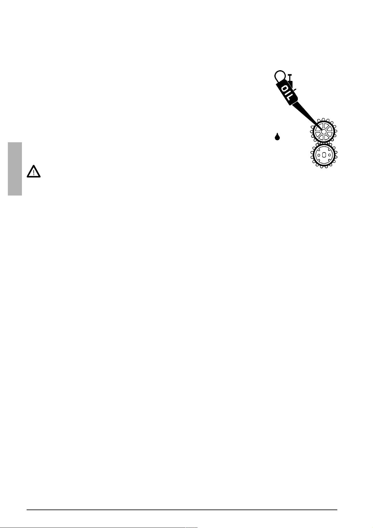
Adjustment of tightness of wire reel brake
Brake force is adjusted through a hole in the locking device of reel hub by tightening/loosening the adjustment
screw with a screwdriver.
Adjust the brake force as so big that the wire does not
spill from the full reel when the rotation of the reel stops.
adjustment screw
Make sure that the welding gun is designed for maximum welding current! Never use a damaged welding gun!
The need for brake force is increased with wire feed speed.
Standard accessory: 200 mm wire reel adaptor
English
Return current cable
Fasten earth clamp of return current cable carefully, preferably direct to welding piece. Contact surface of the clamp
always should be as large as possible.
Clean the fastening surface from paint and rust!
Use in your Kempoweld equipment copper cables. Too small cross-sectional area might cause overheating of
connectors and insulations. Make sure that the welding gun is designed for maximum welding current! Never use a
damaged welding gun!
Shielding gas
As MIG shielding gas uses carbon dioxide, mixed gases and argon. Shielding gas flow rate is defined by welding
current size. The typical rate of gas in welding of steel is 8-15 l / min.
Gas flow regulator
Gas flow regulator should be suitable for shielding gas. The regulator used may be different to the one in picture.
However, following general instructions are valid for all pressure regulators.
Before mounting of flow regulator
Step aside and open cylinder valve (51). This way
you can blow out any dirt that may be in the valve of
bottle.
Turn the press regulation screw (52) of the regulator
outwards until no spring pressure can be felt (screw
is turning freely).
Close needle valve (53) if there is one in the regulator.
Connect regulator onto valve of bottle
Tighten connecting nut (54), preferably with a wrench.
Attach hose spindle (55) of regulator with jacket nuts
(56) onto the. Connection should be ensured with a
hose clamp (57).
Connect the hose onto the regulator and machine,
and tighten the jacket nuts.
55
56
57
P1P2
51
53
54
52
56
0040 / 1921710E / 9
Page 10
Open valve of bottle slowly
The pressure meter (P1) shows the pressure of the bottle. Send the bottle for filling when the bottle pressure
reads 2 bar. Never use the whole contents of the bottle.
Open needle valve if there is one in the regulator.
Turn regulation screw (52) inwards until hose pressure meter (P2) shows flow (or pressure) required. For regula-
tion of flow amount, the machine must be in operation, and the gun switch should be pressed in simultaniously.
Close valve of bottle after welding has stopped
If the machine will be out of use for a long period of time, you should unscrew the pressure regulation screw (52).
Gas bottle
The gas bottle may explode if it falls!
Always fasten the gas bottle firmly in vertical position, to a wall stand or bottle cart, specially designed for it!
For safety reasons always remove the gas bottle from the transport stand of the machine before lifting or car
transport of machine!
Operation and use of power source
See the Main parts.
Main switch
English
In the zero position all control and welding current circuits of the equipment are dead (without voltage). In position I
the control circuits of the machine become live. The welding circuit is dead, if the welding mode has not been started
with the gun trigger.
Always switch the machine on and off from the main switch. Never use the mains plug for turning the units
on and off!
Adjustment of welding voltage
Table of adjustments, switch positions:
Kempomat 2001 Kempomat 2501
voltage step / open circuit voltage voltage step / open circuit voltage
1 / 1 17,5 V 2 / 1 24,8 V 1 / 1 17,3 V 3 / 1 25,5 V
1 / 2 18,5 V 2 / 2 26,8 V 1 / 2 18,0 V 3 / 2 27,1 V
1 / 3 19,6 V 2 / 3 29,0 V 1 / 3 18,8 V 3 / 3 28,9 V
1 / 4 20,8 V 2 / 4 31,6 V 1 / 4 19,7 V 3 / 4 30,9 V
1 / 5 22,0 V 2 / 5 34,5 V 2 / 1 20,7 V 4 / 1 33,0 V
1 / 6 23,3 V 2 / 6 37,5 V 2 / 2 21,7 V 4 / 2 35,6 V
NOTE ! Table values are measured with rated supply
voltage 240 V.
The welding voltage is adjusted with two turn switches. There is the switch for coarse control, where voltage value
of each step can be fine-adjusted with the second switch.
2 / 3 22,9 V 4 / 3 38,7 V
2 / 4 24,1 V 4 / 4 42,3 V
Pilot lamps
Pilot lamps of the machine report about electric function:
The white pilot lamp is illuminated in position I, indicating that the machine is connected to mains voltage.
The yellow pilot lamp is illuminated, when thermal protection of the machine has been released due to overheating.
The protection releases if the power source is continuously loaded over rated values or the cooling air circulation
has been obstructed.
The cooling fan cools down the machine and after the pilot lamp has switched off. The machine is again ready for
welding from the gun trigger.
Control fuse
On the rear plate of the power source, the control fuse 8 A delayed is the short-circuit protection. Use the fuse size
and type according to markings. Damage caused by the wrong type fuse is not covered by the guarantee.
Adjustment for arc force I , II
Arc force is set by connecting the return current cable to one of the two dix-connectors on the front plate.
The connector marked with symbol I gives a rougher arc, which is used for welding of thin sheets and ferrous
metals by lower currents. Especially consider CO2 shielding gas.
The connector marked with symbol II is suitable for greater currents and especially for aluminium and stainless
materials. The most suitable force is, however, most dependent on the welding case. You will find the best results by
testing the different positions.
10 / 1921710E / 0040
Page 11

Operation of cooling fan
The Kempomat 2001 has one cooling fan and the Kempomat 2501 has two cooling fans. The cooling fun is started
and stopped according to use of machine. The cooling fan is started after ca. 30 s after weld start and stopped after
ca. 5 - 7 min after weld end or release of the thermal protection.
Note! The fan is taking in air from rear plate side!
Don´t switch off the unit with the main switch before the cooling fan has automatically stopped. By open
circuit the cooling fan does not start.
Control panels and adjustments
Wire feed speed potentiometer
The wire feed speed is adjusted with the potentiometer on the front panel, see the paragraph Wire feed panel.
Burn back time
Different filler materials and shielding gases behave in different ways in completion of welding, so the welding
current should be switched with delay suitable, according to the welding case.
If you try to cease welding with an unsuitable burn back time, the wire will burn in the contact tip, there will be too
large an amount of wire at the wire end, or the wire will stick at the stopping point.
Factors influencing on the delay:
The wire feed speed has a significant influence on required burn back time. For low wire feed speeds
always select the short burn back time.
5
6
4
3
2
1
ø
7
8
9
10
1 3 5 4 2
Wire inch
The wire inch starts the wire feed motor and mechanism, but not the power source.
The filler wire can be driven to the feeder unit and gun also with the welding gun´s switch, but the power source will
start and the wire becomes live, and this can cause a dangerous situation by accidental contact with surrounding
objects!
Within the instruction label, starting points for adjustment
are given. The fine-adjustment should be carried out according to each case in question.
1. Melting of aluminium is much quicker than by the
other material, so that the burn back time is shorter.
2. Steel and especially filler wires require a longer time
than stainless materials.
3. Thicker filler wires require more time. Also, by the increase of wire feed speed, the required time should be
increased.
4. Memory scale for potentiometer.
5. Wire inch
English
KMW timer
The standard control includes the welding with the closed-open operation of the gun trigger, this is called the
2-sequence procedure. The KMW timer also has the 4-sequence procedure, with which you can release the trigger
for the duration of the welding, as well as the wire feed timer, which helps to control the spot or cycle arc welding.
2 / 4-sequence procedure (see Wire feed panel)
2-sequence procedure The welding with the
2-sequence trigger procedure of the gun.
1. Switch pressed: welding starts
2. Switch open: welding stops
Spot, cycle arc and continuous welding (is operating only in the 2-sequence procedure position)
Spot welding
1. Set the spot time with the potentiometer.
2. The gun switch pressed: welding starts
3. Welding ends automatically after the set time
Cycle arc welding
1. Set the welding cycle time with the potentiometer. The pause time is constant ca. 0,3 s.
The pause time length can be adjusted from the control card trimmer as 0,2 - 1,0 s.
2. The gun switch pressed: welding is started and continued for so long as the switch remains compressed.
4-sequence procedure The welding with the
4-sequence trigger procedure of the gun.
1. Switch pressed: shielding gas is flowing
2. Switch open: welding starts
3. Switch pressed: welding stops
4. Switch open: gas flow stops after the post gas time
0040 / 1921710E / 11
Page 12
Operation disturbances
The amount of usage and the working environment should be taken into consideration when planning the frequency
of maintenance of the Kempomat. Careful use and preventive maintenance will help to ensure problem-free operation.
The following maintenance operations should be carried out at least every six months.
Wire feed:
The wear of the grooves of the feed rolls. Excessive wear of grooves causes prob-
lems in wire feed.
The wear of the wire guide tubes of the wire feeder unit. Badly worn feed rolls and
wire guide tubes should be discarded.
The wire guide tube should be set as near the feed rolls as possible, but not in
contact. The wire must follow a straight line from the end of the tube to the groove of
the feed roll.
Reel brake adjustment.
Electric connections
* Oxidised couplings must be cleaned
* Loose couplings must be tightened
Clean dust and dirt from the equipment.
When using compressed air, always use proper eye protection.
English
In case of problems contact your KEMPPI dealer.
Cables
Check the condition of welding and connection cables daily. Do not use faulty cables!
Make sure that the mains connection cables in use are safe and in accordance with regulations!
The repair and mounting of mains connection cables should be carried out only by an authorised electrician.
twice a
year
Power source
NOTE! Disconnect the plug of the power source from the mains socket before removing the cover plate.
Check at least every 6 months (twice a year):
Electric connections of the unit - clean the oxidised parts and tighten the loosened ones.
NOTE! You must be clear of the correct tension torques before starting the repair of the joints.
Clean the inner parts of the machine from dust and dirt e.g. with soft brush and vacuum cleaner.
Do not use compressed air. Do not use pressure washing devices!
There is a risk that dirt is packed even more tightly into gaps of components!
Only authorised electrician should carry out repairs to the machines.
Regular maintenance of the equipment
Kemppi service repair shops provide regular maintenance in accordance with the agreement.
The major points in the maintenance procedure are listed as follows:
Cleaning of the machine
Checking and maintenance of the welding tools
Checking of connectors, switches and potentiometers
Checking of electric connections
Metering units checking
Checking of mains cable and plug
Damaged parts or parts in bad connection are replaced by new parts
Maintenance testing. Operation and performance values of the equipment are checked, and adjusted when
necessary by means of test equipment.
The amount of use and the working environment should be taken into consideration when planning the frequency of
maintenance of the machine. Careful use and preventive maintenance will help to ensure problem-free operation.
12 / 1921710E / 0040
Page 13

Technical data
Kempomat 2001 Kempomat 2501
Rated voltage
Mains cable / fuse delayed
Connection voltage 220 V -10 % ... 240 V +6 %
Connection capacity 30 % ED
Loading capacity
(nominal values)
Cont rol range
Voltage steps
Open circuit voltage 14 - 40 V 14 - 45 V
Open circuit power < 50 W
Efficiency 200 A / 24 V 70 % 250 A / 26 V 75 %
Power fact or 200 A / 24 V 0,80 250 A / 26 V 0,80
Control fuse 8 A delayed
Wire feeder unit
Diameter of f eed roll
Wire feed speed
Filler w ir e s ø Fe, Ss
60 % ED
100 % ED
30 % ED
60 % ED
100 % ED
ø Cored wire
ø Al
1 ~ 240 V
3 × 2, 5 mm
200 A / 24 V
140 A / 21 V
110 A / 19,5 V
30 - 200 A / 13 - 24 V
2
/ 20 A
9,0 kVA
6,0 kVA
4,0 kVA
12 steps
0...18 m / min
0,6...1,0 mm
0,8...1,2 mm
1,0...1,2 mm
1 ~ 240 V
3 × 4, 0 mm2 / 25 A
12,0 kVA
8,0 kVA
5,2 kVA
250 A / 26,5 V
180 A / 23 V
135 A / 20,5 V
30 - 250 A / 13 - 26,5 V
16 steps
2-r o ll dr ive
32 mm
English
Wire reel max. w eight
max. s ize
Gun co nnec tor Euro
Temperature class
Operation temperature rangee
Storage temperature range
Degree of protect ion
External dimensions length
width
height
Weight 76 kg 82 kg
The products meet conformity requirements for CE marking.
20 kg
ø 300 mm
H (180 °C)
-20...+40 °C
-40...+60 °C
IP 23C
910 mm
420 mm
840 mm
0040 / 1921710E / 13
 Loading...