

Page 1
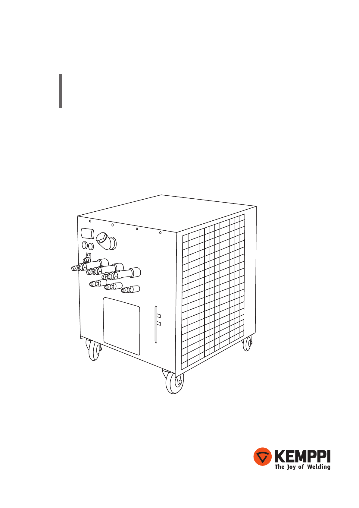
KempCool
40
Operating manual
EN
Page 2

Page 3

OPERATING MANUAL
English
Page 4

CONTENTS
1. Introduction ......................................................................................................................... 3
1.1 General ....................................................................................................................................... 3
1.2 About the product ................................................................................................................. 3
1.3 Properties .................................................................................................................................. 4
2. Installation ............................................................................................................................. 6
2.1 Connecting the cooling system ........................................................................................ 6
2.2 Electrical connection ............................................................................................................. 6
3. Taking the machine into use .................................................................................... 6
3.1 Service and maintenance .................................................................................................... 6
3.2 Troubleshooting .....................................................................................................................7
3.3 Water quality ............................................................................................................................ 7
3.4 Temperature control PJ 33 .................................................................................................. 8
3.5 Disposal of the machine ...................................................................................................... 9
EN
4. Ordering numbers ........................................................................................................... 9
5. Technical data ..................................................................................................................... 9
6. Main circuit diagram ....................................................................................................10
2
KempCool 40
Page 5

1. INTRODUCTION
1.1 General
Congratulations on choosing the KempCool equipment. Used correctly, Kemppi products
can signicantly increase the productivity of your welding, and provide years of economical
service.
This operating manual contains important information on the use, maintenance and safety of
your Kemppi product. The technical specications of the equipment can be found at the end
of the manual.
Please read the manual ans Safety Instructions booklet carefully before using the equipment
for the rst time. For your own safety and that of your working environment, pay particular
attention to the safety instructions.
For more information on Kemppi products, contact Kemppi Oy, consult an authorised Kemppi
dealer, or visit the Kemppi web site at www.kemppi.com.
The specications presented in this manual are subject to change without prior notice.
NOTE! Items in the manual that require particular attention in order to minimise damage and
personal harm are indicated with this symbol. Read these sections carefully and follow their
instructions.
Disclaimer
While every eort has been made to ensure that the information contained in this guide
is accurate and complete, no liability can be accepted for any errors or omissions. Kemppi
reserves the right to change the specication of the product described at any time without
prior notice. Do not copy, record, reproduce or transmit the contents of this guide without
prior permission from Kemppi.
EN
1.2 About the product
KempCool 40 is an ecient water cooling device designed for use with Kemppi's tandem
robotic welding equipment, KempArc Pulse TCS. It can be used for water cooling of two
welding guns, operating in a tandem welding environment. KempArc Pulse TCS can also be
used with other mechanised welding equipments, when extremely high ability of cooling is
demanded.
KempCool 40 is equipped with three water ow circuits, one for each contact tip and an
optional circuit for cooling the gas nozzle. Each water ow circuit has its own ow control, and
the low-pressure alarm can be adjusted to the desired level.
Range of application
The KempCool 40 cooling unit is designed to be used with Kemppi's KempArc welding
equipments.
© Kemppi Oy / 1204
3
Page 6

1.3 Properties
Description and operation principle
KempCool 40 is an ecient water cooling device. It is equipped with a fan and a radiator using
water or special non-freezing liquid as a coolant. The operating temperature range of the
device is 5…40 °C (plain water) or -20…+40 °C (non-freezing liquid) .
Excess heat is removed from the coolant with a fan. When the temperature of the coolant
rises above a set level, heat exchanger is activated and the fan starts to operate, until
the temperature gets below the set level. The activation level can be adjusted inside the
KempCool 40 cooling unit. See instructions later in this manual.
Cooling capacity
Nominal cooling capacity is 4 kW. The temperature of the coolant is always higher than the
surrounding air by 0 to 8 °C.
NOTE! Whenever the unit is idle for longer periods of time, or if the temperature may occationally
drop below freezing point during storage or transport, empty all water ow circuits to avoid frost
damage, or make sure that the cooling brine is of non-freezing kind.
NOTE! Do not use inammable or explosive liquids.
EN
NOTE! To get special non-freezing cooling brine, please contact Kemppi Oy.
Cooling circuit
The KempCool 40 cooling device is equipped with an eective pump, which makes the
coolant continuously circulate between the heat exchanger and the welding gun. In the
welding end, the coolant absorbs heat, which is transferred to the ambient air in the heat
exchanger.
With the ow control screw you can control the ow of the cooling liquid. The level of coolant
container must be checked regularly and lled if needed.
NOTE! Avoid running the pump dry.
NOTE! Ensure that there is at least 40 cm free space on both sides of the machine for eective
cooling air circulation.
Cooling air
If surrounding air is heavily contaminated with particles of dust, install a lter to clean the
incoming cooling air. The lter is available as an optional accessory. The lter must be regularly
checked and replaced if needed.
Flow control
There is a ow control screw in all return lines of the cooling circuit. With this screw you can
adjust the coolant ow rate. Malfunction is indicated with a signal light in front of the cooling
unit.
Pressure alarm limit
If circulation of the coolant is for some reason weakened due to a fault somewhere in the
cooling circuit, the coolant pressure drops and the red signal light shows alarm.
With the control device located inside the cooling unit, you can set the pressure level where
the alarm is triggered.
4
KempCool 40
Page 7

Slide block
Hex screw
Alarm limit pointer
(switch-o-point)
Setting the alarm limit for coolant pressure:
1. Attach the water hoses to the cooling water connectors on the front of the unit, and start
the unit from the main switch.
- If the ambient temperature is below 35 °C, only the pump starts.
2. Using the ow adjustment screws on the water hose connectors, set the ow rate to the
same value (e.g. 0.5–1 l/min) on each outgoing water line.
3. Remove the side panel on the left of the unit (looking from the front).
4. Loosen the hex screw on top of the ow controller (see the picture).
5. Move the slide block, until an alarm is given.
- If the unit is connected to a FastMig welding device, the alarm appears as a cooling unit
error on the power source's control panel.
6. Move the slide block a little backwards, until the alarm stops.
7. Lock the slide block in its place by xing the hex screw on the top.
8. Test the alarm by disconnecting one of the water lines. If there's no alarm, the set limit
value is too low, and you should adjust the limit to higher value.
9. When the alarm limit is on desired level, tighten the slide block in its place and replace
the side panel.
NOTE! The cooling fan starts when the temperature of the cooling water rises above 35 °C. The
pump starts to circulate the cooling water as soon as you start the unit from the main switch. The
pump has a thermostatic control, which allows longer maintenance intervals, because the unit
gets less dust inside with the fan not operating.
EN
© Kemppi Oy / 1204
5
Page 8

2. INSTALLATION
2.1 Connecting the cooling system
Fill the coolant container through the lling tube. When the maximal level is reached, the
built-in mechanical oat switch breaks the water delivery. At the same time, circulation pump
starts to operate for a while to allow automatic ventilation of the system.
NOTE! The transfer pump must be switched on only when the system is completely lled. Running
dry can damage the pump.
If the cooled welding torches are located higher than the radiator, the coolant starts to ow
back when you switch o the pump, and the coolant container may overow. In this case you
can set a check valve (either magnetic or manual) in the ow circuit.
2.2 Electrical connection
All local electrical and electronic regulations must be complied with when making the
electrical connections. Before taking the equipment into use, check that the environment
fulls the following requirements.
EN
Mains voltage
Max. fuse protection
Wire cross section
230 V, 50 Hz
10 A
1.5 mm
3. TAKING THE MACHINE INTO USE
When you have lled the cooling system and made the necessary electrical connections, you
can turn on the heat exchanger group. The pump starts when you switch the device on.
If the desired pressure is not reached, please do as follows:
1. Check the coolant level in the cooling system and ll if necessary.
2. Check all joints.
3. Ventilate the system one more time.
3.1 Service and maintenance
The heat exchanger does not require any special servicing. However, it is recommended to
check regularly the hoses and connections for leaks.
NOTE! Always ensure that the voltage is switched o when carrying out any kind of maintenance
or service work on the KempCool 40 cooling device.
NOTE! Do not change electronic connections or make any technical modications on the machine.
For repair work, contact authorised Kemppi service workshop.
6
KempCool 40
Page 9

3.2 Troubleshooting
Problem Cause Action
Insufficient cooling
capacity
Pump does not start
Flow alarm is on (the
red warning light on the
front panel)
The heat exchanger and/or air lter is
dirty. Clean the components.
Cooling air temperature is too high. Check the air temperature.
Cooling system is overloaded. Remove any extra cooling consumers.
The coolant temperature is too high
(> 40 °C).
Thermal protection of the pump motor
has gone o.
The coolant level is too low. Check the cooling system for leaks and add more
Clean the components.
Check thermoregulator setting. Replace if
necessary.
Check the fuses.
coolant if needed.
3.3 Water quality
Subject to the equipment to be cooled or heat-balanced, certain requirements have to be met
by the cooling water regarding purity. The degree of the water`s contamination, as well as the
size and construction of the heat-exchanging- or -balancing plant determine the process most
suitable for the application of additives and/or care of the water-supply in question. You can
use normal tap water when lling the tanks.
With deviating water-quality, we recommend using the services of consultants, or to have a
water analysis or water sample sent to us.
Kemppi is not liable for any malfunctions or damages arising from deviating water qualities.
When employing chillers at temperatures below + 8°C, an anti-freeze medium must be added.
EN
© Kemppi Oy / 1204
7
Page 10

3.4 Temperature control PJ 33
m
u
t
e
When you turn the main switch to position 1, the circulating pump starts. If the temperature
of the coolant is higher than the temperature set at the thermoregulator, the cooling fan
also starts automatically. Otherwise, the desired cooling temperature must be set at the
thermoregulator.
Changing the set point
EN
m
u
t
e
2.
1. Unlock the set point with a long press of the up arrow key (3 s).
2. Increase the set point value by pressing the up arrow key or decrease it by pressing the
down arrow key.
3. When you have set the value, wait until the display returns to its initial state. The new
setting is saved automatically.
You can also use the SET button to return to initial state.
Indicator lights
1.
3.
4.
8
If led 3 shows white, the compressor is in operation.
If led 4 shows red, there is a fault (see the errors list).
KempCool 40
Page 11

3.5 Disposal of the machine
Do not dispose of electrical equipment with normal waste!
In observance of European Directive 2002/96/EC on waste electrical and electronic
equipment, and its implementation in accordance with national law, electrical equipment
that has reached the end of its life must be collected separately and taken to an appropriate
environmentally responsible recycling facility.
The owner of the equipment is obliged to deliver a decommissioned unit to a regional
collection centre, per the instructions of local authorities or a Kemppi representative. By
applying this European Directive you will improve the environment and human health.
4. ORDERING NUMBERS
KempCool 40
5. TECHNICAL DATA
KempCool 40
Operating voltage
Connection capacity
Cooling power
Start pressure, max.
Cooling liquid
Tank volume
External dimensions
Weight
Operating temperature range
Storage temperature range
EMC class
Degree of protection
6208400
EN
230 V AC ±10 %
100 % ED 300 W
4.0 kW
0.35 MPa (= 3.5 bar)
20–40 % ethanol+water
8 l
LxWxH 700 x 600 x 600 mm
40 kg
–20…+40 °C (non-freezing liquid)
–40…+60 °C
A
IP23S
© Kemppi Oy / 1204
9
Page 12

6. MAIN CIRCUIT DIAGRAM
L
3
S1
4
2
EN
PJ Easy
230V
50/60 Hz
N
M1
R1
1
L L
M
~
N N
PE PE
pump
9
10
-N1
fan red white
M2
Kompr.
M
~
2
468
AUX
1 3 14
5711
1 11
B1 -K1
A1 x1 x1
K1
A2 x2 x2
Contact open if fault
H1 H2
10
-K1
B2
KempCool 40
11
14
4K7
15k
1 2 3 4 5 6
female
10k
B1 ow control
M1 pump
M2 fan
N1 temperature controller
R1 temperature sensor
S1 on/o switch
B2 AMP connector (connector to
KempArc power source)
K1 Relais Alarm
H2 power on lamp
H1 alarm lamp
Page 13

Page 14

KEMPPI OY
Kempinkatu 1
PL 13
FIN-15801 LAHTI
FINLAND
Tel +358 3 899 11
Telefax +358 3 899 428
export@kemppi.com
www.kemppi.com
Kotimaan myynti:
Tel +358 3 899 11
Telefax +358 3 734 8398
myynti.@kemppi.com
KEMPPI SVERIGE AB
Box 717
S-194 27 UPPLANDS VÄSBY
SVERIGE
Tel +46 8 590 783 00
Telefax +46 8 590 823 94
sales.se@kemppi.com
KEMPPI NORGE A/S
Postboks 2151, Postterminalen
N-3103 TØNSBERG
NORGE
Tel +47 33 346000
Telefax +47 33 346010
sales.no@kemppi.com
KEMPPI DANMARK A/S
Literbuen 11
DK-2740 SKOVLUNDE
DANMARK
Tel +45 4494 1677
Telefax +45 4494 1536
sales.dk@kemppi.com
KEMPPI BENELUX B.V.
Postbus 5603
NL-4801 EA BREDA
NEDERLAND
Tel +31 765717750
Telefax +31 765716345
sales.nl@kemppi.com
KEMPPI (UK) Ltd
Martti Kemppi Building
Fraser Road
Priory Business Park
BEDFORD, MK44 3WH
UNITED KINGDOM
Tel +44 (0)845 6444201
Telefax +44 (0)845 6444202
sales.uk@kemppi.com
KEMPPI FRANCE S.A.S.
65 Avenue de la Couronne des Prés
78681 EPONE CEDEX
FRANCE
Tel +33 1 30 90 04 40
Telefax +33 1 30 90 04 45
sales.fr@kemppi.com
KEMPPI GmbH
Otto-Hahn-Straße 14
D-35510 BUTZBACH
DEUTSCHLAND
Tel +49 6033 88 020
Telefax +49 6033 72 528
sales.de@kemppi.com
KEMPPI SPÓŁKA Z O.O.
Ul. Borzymowska 32
03-565 WARSZAWA
POLAND
Tel +48 22 7816162
Telefax +48 22 7816505
info.pl@kemppi.com
KEMPPI AUSTRALIA PTY LTD.
13 Cullen Place
P.O. Box 5256, Greystanes NSW 2145
SMITHFIELD NSW 2164
AUSTRALIA
Tel. +61 2 9605 9500
Telefax +61 2 9605 5999
info.au@kemppi.com
OOO KEMPPI
Polkovaya str. 1, Building 6
127018 MOSCOW
RUSSIA
Tel +7 495 739 4304
Telefax +7 495 739 4305
info.ru@kemppi.com
ООО КЕМППИ
. 1, 6
127018
Tel +7 495 739 4304
Telefax +7 495 739 4305
info.ru@kemppi.com
KEMPPI, TRADING (BEIJING) COMPANY,
LIMITED
Room 420, 3 Zone, Building B,
No.12 Hongda North Street,
Beijing Economic Development Zone,
100176 Beijing
CHINA
Tel +86-10-6787 6064
+86-10-6787 1282
Telefax +86-10-6787 5259
sales.cn@kemppi.com
肯倍贸易(北京)有限公司
中国北京经济技术开发区宏达
北路12号
创新大厦B座三区420室 (100176)
电话:+86-10-6787 6064
+86-10-6787 1282
传真:+86-10-6787 5259
sales.cn@kemppi.com
KEMPPI INDIA PVT LTD
LAKSHMI TOWERS
New No. 2/770,
First Main Road,
Kazura Garden,
Neelankarai,
CHENNAI - 600 041
TAMIL NADU
Tel +91-44-4567 1200
Telefax +91-44-4567 1234
sales.india@kemppi.com
www.kemppi.com
1920180
1204
 Loading...